A schematic diagram for half of a continuous coaxial nozzle is shown in
Figure 1. A laser beam passes through the central cavity of the structure, and the powder particles are transported in the annular passage, which has a cone shape that is coaxial with the laser beam. The geometric profiles of the nozzle and the powder flow field below it at any symmetry plane are shown in
Figure 2. The annular nozzle has a cone angle of
θn relative to the laser beam center line (z-axis). The powder jet at the nozzle outlet usually diverges to a certain extent, which can be characterized by the upper and lower divergence angles
θp1 and
θp2, respectively. Due to the interaction of gravity, the carrier gas, and the shielding gas, the divergence angles are generally small but not zero. The virtual focus of the powder jet in the nozzle is denoted as O
1 and O
2, and the upper and lower edge lines are denoted as O
1A and O
2A, and O
1B and O
2B, respectively. The powder particles ejected from the annular nozzle outlet flow down and experience a process first of convergence and then of divergence, during which a waist region with a certain width and length is formed at the central area of the laser beam.
As can be seen in
Figure 2, the annular powder stream gradually converges to the central area and into a circular stream at the horizontal section with point A. Then, the cross-section of the circular stream gradually narrows, and the powder concentration gradually increases. The convergence is completed at the CD plane, which can be regarded as the focal plane of the powder stream. At the CD plane, the distribution of powder particles is most concentrated. Below the CD plane, the cross-section of the powder stream gradually increases with the increase in the distance from the CD plane. On the horizontal section with point B, where the intersection of the lower edge lines of the powder jet is located, most of the particles fall outside the focus diameter, and the powder stream shows significant divergence characteristics. Most of the powder particles are concentrated near the centerline in the region between points M and N, which is called the waist region of the powder stream [
19]. According to the particle distribution characteristics on the horizontal section plane at different locations, the powder stream can be roughly divided into three stages [
19], i.e., the pre-waist, waist, and post-waist stages, as shown in
Figure 2.
Although the typical geometric characteristics of the powder stream have been determined in experimental tests and numerical simulations under specific process parameters, the intrinsic geometric relationship between these values and their calculation methods has not yet been revealed due to the lack of analytical analysis. Therefore, these values are only applicable to the specific processes given in the literature and cannot be widely applied. In this section, the intrinsic geometric relationship related to the powder flow and nozzle parameters is analyzed and elaborated. The analytical formulas are derived to estimate the main geometric characterization of the powder stream, including the focal plane position, waist width, and starting and ending positions of the waist region.
2.1. Focal Plane Position of the Powder Stream
The focal plane position of the powder stream is a key factor in the laser-based direct energy deposition process, which provides a basic and important reference for the determination of the optimal placement position of the substrate. It can be observed in
Figure 2 that the focal plane of the powder stream is the CD plane, and its position can be indicated by the distance from the nozzle outlet to the CD plane. The local geometric diagram is enlarged for the convenience of elaboration, as shown in
Figure 3.
dIn is the inner diameter of the annular nozzle, and
H is the width of the powder passage. C
1 is the intersection of O
1C and the outer wall of the powder passage, and C
2 is the intersection of O
2C and the inner wall of the powder passage. A vertical line from point C to C
1C
2 is drawn, and the vertical foot is P. The distance from the nozzle outlet to the CD plane, i.e.,
LCD, is equal to the length of the line segment CP.
The length of segment C
1C
2 can be expressed by the nozzle parameters as
dIn +
H/cos
θn. It can be seen in
Figure 3 that
; thus, the following equation is obtained:
According to the geometric relationship shown in
Figure 3,
,
. Substitution of them into Equation (1) results in the expression for
LCD as shown below:
Equation (2) is the formula for the calculation of the focal plane position. From this equation, it can be seen that the focal plane position
LCD is related to the inner diameter
dIn, nozzle inclination angle
θn, the width of the powder passage
H, and the divergence angles of the powder jet at the nozzle outlet
θp1 and
θp2.
LCD has linear relationships with
dIn and
H and non-linear relationships with the other parameters in Equation (2).
Figure 4 shows the effects of each parameter on
LCD when the other parameters remain constant (
dIn = 4 mm,
θn = 30°,
H = 1.5mm,
θp1 = 5°, and
θp2 = 10°), which shows that the focal plane position changes monotonously with these parameters.
The variables dIn, θn, and H are structural parameters of the nozzle. The focal plane position will move down if the inner diameter dIn of the nozzle and/or the width of the powder passage H is enlarged, while it will move up when the inclination angle θn of the nozzle increases. The structural parameters dIn and θn have an obvious influence on the focal plane position for the given variation ranges, while the structural parameter H has a small impact. The divergence angles θp1 and θp2 are both processing-related parameters, which could also affect the focal plane position. They have opposite effects on LCD, and their effects are nearly linear. The focal plane position will move up if θp1 increases and move down if θp2 increases and a shift of about 1 mm will be caused in the given variation ranges. Thus, the focal plane position will shift when the processing parameters change even though the structural parameters are fixed.
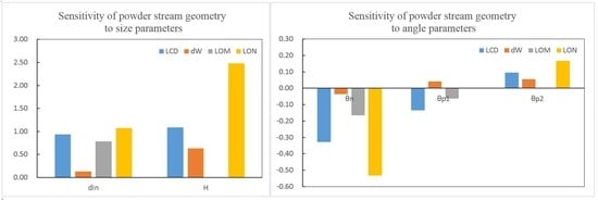
Table 1 gives the sensitivity of
LCD to each parameter, which provides the quantitative characterization for the impact of unit change of each parameter.
θn has an obvious non-linear effect on
LCD, and, thus, a variation range of the sensitivity value is given. From this table, size parameters
dIn and
H are two highly sensitive factors for
LCD, and they have similar effects. The angle parameter
θn is sensitive when its value is small (20°~25°), while its effect weakens when its value increases, and it has a similar effect with that of
θp1 when
θn > 30°. The angle parameter
θp2 is a slightly sensitive factor compared with
θn and
θp1.
In Equation (2), the upper and lower divergence angles (
θp1 and
θp2, respectively) of the powder jet at the nozzle outlet are considered, while their effects have been ignored in some previous works [
9], and the focal plane position of the powder stream is approximately taken as the intersection point of the powder passage centerlines, i.e.,
from Equations (2) and (3), which means that the focal plane position of the powder stream is no longer at the intersection of the powder passage centerlines when considering the divergence of the powder jet at the nozzle outlet, which is consistent with the conclusion in [
12].
only when
. Nevertheless, the fact is that the divergence angle of the powder jet is usually not zero due to the influence of gravity combined with inner/outer shielding gas, and the upper divergence angle is generally less than or equal to the lower divergence angle, i.e.,
θp1 ≤
θp2 [
13,
15]. The effects of divergence angles are discussed in detail below.
The difference between Equations (2) and (3) lies in the denominator, and it can be expressed as follows:
If
, the relative error
δ can be expressed as
Equation (5) shows that the relative error is a function of the quadratic term of the divergence angle. According to references [
13,
16,
17,
19,
20], the value of
θn usually lies in the range of 20°~30°. If
θn = 30°, we have
; the curve of
δ versus
θp is shown in
Figure 5.
It can be seen in
Figure 5 that
δ ≤ 0.01 when
θp ≤ 5°. That is, the difference between Equations (2) and (3) is negligible when the divergence angle is less than 5°, and the focal plane position of the powder stream is very close to the intersection position of the powder passage centerlines. When
θp > 5°, the difference between the two shows a non-linear increasing trend with the increase in the divergence angle.
When
, the relative error
δ can be expressed as follows:
Substitution of
θn = 30° into Equation (6) gives
The surface of
δ versus
θp1 and
θp2 is shown in
Figure 6.
From Equations (6) and (7) and
Figure 6, when
, the relative error is not only related to the values of
θp1 and
θp2 but also to the difference between them. Besides, since
δ1 < 0 and
δ2 > 0, the value of
δ may be positive, negative, or zero. If
δ is positive,
; the focal plane of the powder stream is located above the intersection of the powder passage centerlines. If
δ is negative,
; the focal plane of powder stream is located below the intersection of the powder passage centerlines. Especially, if
δ is zero,
; the focal plane position of the powder stream coincides with the intersection point of the powder passage centerlines.
In this subsection, the formula for calculating the focal plane position of the powder stream is derived considering the analytic geometry approach, and the relationship between the focal plane position and the intersection of the powder passage centerlines is comprehensively analyzed, which provides a theoretical reference for the understanding and determination of the focal plane position of the powder stream.
2.2. Waist Width of the Powder Stream
The prediction of the waist width is useful for the prediction of the track width and for the selection and adjustment of the laser spot size. According to the geometric relationship shown in
Figure 2, the length of the segment CD can be expressed as follows:
The length of segment C
1O is equal to (
dIn/2 +
H/cos
θn), and the length of segment C
1P is equal to [
LCD × tan(
θn −
θp2)]. Substitution of them into Equation (8) results in
According to the discussion in reference [
19], the waist width
dw of the powder stream is defined as the size of the area where the powder has a high concentration (higher than a certain value) rather than where all particles coverage. Thus, the waist width should be expressed as
in which the coefficient
can be determined from the powder distribution in the cross-section. The powder distribution in the waist region follows Gaussian distribution [
8], thus the concentration can be described as
where
Cm is the maximum powder concentration at the center of the stream,
σ is a parameter characterizing the powder stream range, and
r denotes the radius from the center.
The waist width is defined here as the radius with which the powder concentration decreases to 1/e
2 of the maximum value, and it can be determined from Equation (11) that
According to Equation (12), 86.5% of the powder particles lie in the waist width range.
The CD range should contain all of the powder particles in
Figure 3. However, the length of CD satisfying this condition is infinite, according to Equation (11). Therefore, an approximate treatment is needed in the calculation process. The radius corresponding to the CD range is assumed as the position where the powder concentration decreases to 10
−5 Cm (99.999% of the powder particles lie in the range). It can be determined from Equation (11) that
By use of Equations (10), (12), and (13), the following is obtained:
Then, Equation (10) can be rewritten as
Equation (15) is the final expression for the waist width of the powder stream. From this equation, the waist width
is also related to the nozzle inner diameter
dIn, the nozzle inclination angle
θn, the powder passage width
H, and the divergence angles
θp1 and
θp2.
Figure 7 shows the effects of each parameter on
dW when other parameters remain constant (
dIn = 4 mm,
θn = 30°,
H = 1.5 mm,
θp1 = 5°,
θp2 = 10°), which shows that waist width also changes monotonously with these parameters.
The waist width will increase if the diameter of the nozzle inner and/or the powder passage width are enlarged, while it will non-linearly decrease when the nozzle inclination angle increases. The structural parameters dIn and H have an obvious influence on the waist width for the given variation ranges, while the structural parameter θn has a minimal impact. The divergence angles θp1 and θp2 have nearly linear effects on the waist width, and the waist width will increase if θp1 and/or θp2 increase. The changes in θp1 and θp2 could cause a change of about 0.5 mm on waist width, in which θp2 will contribute more as it has a greater impact than that of θp1 for the given variation ranges. Thus, the waist width could be affected by both structural and processing parameters.
Table 2 shows the sensitivity of
dW to each parameter. For the size parameters,
H is a highly sensitive factor for
dW, while
dIn is slightly sensitive. For the angle parameters,
θn has a similar effect on
dW with that of
θp1 and
θp2 when its value is near 20°, and the effect weakens when its value increases. It means that the influence of
θn is less than that of
θp1 and
θp2 when
θn > 20°.
2.3. Starting and Ending Positions of the Waist Region
The prediction of the starting and ending positions of the waist region is mainly used to determine the Gaussian distribution region of the powder concentration, thus as to determine the region where the substrate should be placed. Placing the substrate in the Gaussian distribution region can ensure powder utilization and forming quality [
5,
11]. It is suggested in [
19] that the starting point of the waist region should be defined as the position where the powder flow begins to merge, the powder concentration is Gaussian distribution relative to the centerline of the powder stream, and the ending point is defined as the position where the powder begins to diverge, and its concentration no longer shows obvious Gaussian distribution. According to the definition, the analytical formulas for the starting and ending positions of the waist region are proposed and derived here.
As shown in
Figure 2, the starting point M usually does not coincide with point A but is a certain distance below point A, because the particle concentration on the cross-section with point A does not show an obvious Gaussian distribution. Similarly, the ending point N of the waist region is not coincident with point B but a certain distance above point B, because the powder distribution exhibits significant divergence on the cross-section with point B.
It is adopted here that the starting point M of the waist region is located at the intersection of the bisector of upper divergence angle and the nozzle central axis (OB), and the ending point N is located at the intersection of the bisector of lower divergence angle and the nozzle central axis (OB), as shown in
Figure 8. The specific positions of M and N can be determined by the corresponding geometric relationship in
Figure 8. The lengths of segments OM and ON are computed by
The starting position of the waist region has no relationship with the width of the powder passage
H and/or the lower divergence angle
θp2, and the ending position of the waist region has no relationship with the upper divergence angle
θp1 in Equation (16).
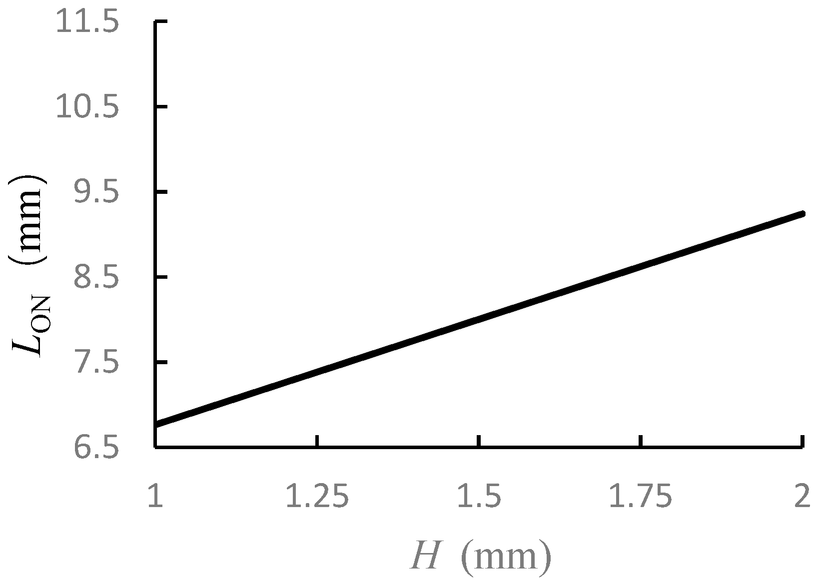
Figure 9 shows the effects of each parameter on segments OM and ON when other the parameters remain constant (
dIn = 4 mm,
θn = 30°,
H = 1.5 mm, and
θp1 = 5°,
θp2 = 10°). From
Figure 9, the starting and ending points of the waist region will both move down with the increase in the inner diameter
dIn, and the length of the waist region will increase linearly. The starting and ending points of the waist region will both move up with the increase of the
θn, and the length of the waist region will decrease non-linearly. The starting point of the waist region will move up with the increase in the upper divergence angle
θp1, while the movement amount is small. The ending point of the waist region will move down with the increase in the width of the powder passage
H and lower divergence angle
θP2, and the length of the waist region will increase linearly.
Table 3 gives the sensitivity of
LOM and
LON to each parameter. For the starting point of the waist region
LOM, the size parameter
dIn is a highly sensitive factor. The angle parameter
θn is a moderately sensitive factor for
LOM, and
θp1 is a slightly sensitive factor. For the ending point of the waist region
LON, the size parameters
H and
dIn are both highly sensitive factors. The angle parameter
θn is a highly sensitive factor when its value is small (
θn < 25°), and its effect weakens when the value increases. The angle parameter
θp2 is also a moderately sensitive factor for
LON.
In this section, some analytical expressions for the geometric characteristics of the powder stream are derived, and they are usable when the collision effect between powder particles is weak, which is a commonly used assumption in process modeling and simulation [
5,
9,
10,
11,
12,
13,
14,
15,
16,
17,
19,
20]. Moreover, these analytical expressions can be used on the basis of that the divergence angles
θp1 and
θp2 are given. Processing-related parameters
θp1 and
θp2 have complicated relationships with processing parameters, and this issue is not discussed in this paper.
The influence of each parameter on the geometric characteristics of the powder stream was comprehensively analyzed based on the analytical expressions. From
Table 1,
Table 2 and
Table 3, structural parameters
H and
dIn are two key factors affecting the powder stream. The structural parameter
θn has moderately sensitive effects on
LCD, LOM, and
LON, and a slightly sensitive effect on
dW. Processing-related parameters
θp1 and
θp2 have moderately sensitive effects on
LCD and
LON, respectively, and they have slightly sensitive effects on
dW and
LOM.


