Abstract
In this work, new customized heat treatments for selective laser melted (SLM) parts in IN718 alloy were analyzed. This was done through the evaluation of the mechanical properties and advanced characterization of the phases and microstructure obtained in as-built condition and after the application of standard and tailored heat treatments. The microstructure and mechanical properties were compared and discussed with results reported in the literature. Finally, strengthening mechanisms of IN718 alloy processed by SLM and its differences with mechanisms that occur in investment casting were analyzed. Both processes generate quite different microstructures, investment casting is composed mainly by a dendritic structure, and SLM is characterized by columnar and cellular structures with very thin cells. Due to the fine and homogeneous microstructure obtained from SLM processing and its specific strengthening mechanisms, it is not necessary to apply homogenization and solution stages as in standard heat treatment used for this type of alloy in casting or wrought. The pre-heating and process parameters selected, in combination with a direct stepped aging (at 720 °C/620 °C), provide the material with its best mechanical properties, which are superior to those obtained by standard heat treatment (AMS 5383F) applied to investment casting of IN718 alloy.
1. Introduction
The nickel-based alloy Inconel 718 (IN718) is of high interest in the aeronautic, aerospace, and oil & gas sectors, due to its good behavior at medium to high temperature applications [1] where creep, corrosion, and heat resistance are needed [2]. It is also a key solution for hot structural applications, and its use is increasing day to day [3]. Additionally, laser-based additive manufacturing (AM) technologies are maturing apace to become alternatives to conventional manufacturing routes. These niche sectors demand high performance components with adequate mechanical properties [4]. Recently, new applications of hybrid manufacturing combining SLM with laser metal deposition (LMD) and machining showed high potential and are promising for the aeronautic and aerospace sectors [5]. This type of hybrid manufacturing approach allows to obtain near-net-shape parts with reduced post-processing steps and lower buy-to-fly ratios.
The aeronautical sector was one of the last sectors to adopt metal AM even with serial production. According to the Wholers report, this industrial sector experienced a growth of 4.3% in 2015 and is the second largest sector in additive manufacturing, representing around 16% of the global market [6]. The 2018 Wholers report concludes that the 3D additive manufacturing industry increased by 21% to a total of $7 trillion in 2017, while the 2019 Wholers report forecasts a growth of $35.6 trillion in the 3D additive manufacturing industry by 2024 [7].
Metal AM offers a large number of very interesting advantages for the aeronautical sector such as the light weighting of the components [8], consequent reduction in fuel consumption, design freedom (possibility of creating complex shapes combining structural optimization with topological optimization) [9], reduction of the purchase price, reduction in buy-to-fly ratio for large parts, simplification of the assembly process, reducing time to market, etc. Therefore, research in process development with AM technologies has increased.
Investment casting is a metal casting process. The process uses wax as a material for the pattern. These patterns are subsequently coated with a ceramic shell in the form of an investiture to generate a non-permanent mould with an upper opening through which the wax is first removed, and whose hollow inner section serves as a mould or metal container; this allows faithful copies of the original model to be made by metal casting. The investment casting process has the following advantages: (1) narrow tolerances and good dimensional accuracy; (2) good surface finish, better, in general, than traditional casting methods; (3) ability to obtain complex geometries and thin wall thickness (around 1 mm); and (4) design flexibility. Both large and small pieces can be cast, although, of course, within limits. Among the limitations of the process, it is worth highlighting the following: (1) limitation in terms of size and weight of the parts, and (2) limitation in terms of mechanical characteristics, since the molten metal is cast into a preheated mould. This makes the cooling process slow, which generates large grain structures and, therefore, mechanical properties (especially elongation) are worse compared to the ones of parts manufactured by other processes, requiring a specific heat treatment to improve them. In the specific case of nickel-based superalloys, the melting and casting processes, as well as the subsequent thermal treatments, are performed under vacuum conditions, which makes the process technologically more complex, consuming large amounts of energy, and the associated costs increase.
The casting industry is following the evolution of metal additive manufacturing technologies, and the SLM process in particular is being closely followed, since the development of this technology and the latest advances can affect foundry in different ways. SLM can be an alternative for the manufacturing of brackets, nozzles, tools, and moulds with improved functionality, and on the other hand, AM can be a real alternative for the manufacturing of certain types of complex parts and components in short series. The use of this technology for direct production of functional parts is increasing, beyond its use to obtain prototypes or casting models.
IN718 is a precipitation strengthening nickel-based alloy. The microstructure consists of face-centered cubic (FCC) supersaturated solution matrix strengthened by γ′-Ni3(Nb,Ti,Al) and γ″-Ni3Nb. Other undesired phases such as laves phases, δ phases, carbides (Cx), and nitrides (TiN) could be found in their microstructure in the as-built and heat-treated conditions [2,10,11,12]. The strengthening effect of this alloy is given by the precipitation of γ′ and γ″ phases. The γ′ phase is a matrix-coherent cubic phase with a spherical size around 20 nm, while γ″ is a tetragonal metastable phase with morphology of thin ellipsoidal discs. These phases precipitate from the supersaturated solid solution during the double aging stage heat treatment, γ′ in the range of 621 °C to 649 °C, and γ″ in the range of 718 °C to 760 °C. The effectiveness of the double aging depends on the Nb concentration and its distribution in the matrix, on the Al/Ti ratio [11] to optimize the mechanical properties, and the relationship between them. Their morphology must be taken into account independent of the manufacturing route of the IN718 alloy [11].
Additionally, Laves and δ phases are usually present in IN718 microstructure. The δ phase is a Ni3Nb orthorhombic phase with Nb content between 6–8% (wt.%). It is formed in the range of 650 °C to 980 °C. It is also formed from γ″ phase in overaging [2,11,12]. The Laves phases are hexagonally close-packed (Ni,Fe,Cr)2(Nb,Mo,Ti) phases with a Nb content between 10–12% (wt.%) and hexagonally close-packed structure. According to different authors, these phases are detrimental to ductility, and fatigue and creep resistance [3,11,13].
To achieve the required mechanical properties, it is necessary to carry out a thermal treatment after SLM and casting processes. This treatment seeks to dissolve the undesired phases and homogenize elements such as Ti, Nb, and Al in the matrix to promote the precipitation of γ′ and γ″. In addition, with the thermal treatment it is possible to relieve the stresses generated during the rapid cooling produced in SLM processing. That is the main reason to develop and study new tailored heat-treatments for IN718 parts produced with metal additive manufacturing.
The aim of this work is to analyze and compare the microstructure and mechanical properties of IN718 alloy obtained by selective laser melting and investment casting processes, in as-built/as-cast condition and under different heat treatments. The knowledge of the strengthening mechanisms and aging response of IN718 SLM alloy and their correlation with mechanical properties will allow the scientific and industrial community to have a better understanding of the mechanical behavior for this alloy obtained by laser-based additive manufacturing technique. Also, the comparison will be useful for future analysis of whether a material manufactured by SLM can be an alternative to the industrial casting process for commercial nickel-based alloys available to date, and for aeronautical applications at medium to high temperature where it could be economically viable, in particular, for short production of geometrically complex parts with improved functionalities.
2. Materials and Methods
For the SLM process, IN718 gas atomized pre-alloyed powders were studied in detail to ensure their flowability, spherical morphology, low internal porosity level, and chemical composition in an initial benchmarking of four commercial powders from different suppliers. Finally, IN718 powder manufactured by CARPENTER Additive (UK) was selected, in particular the CT PowderRange IN718F grade powder, which has a specified particle size distribution of 10–45 µm. The chemical composition of this powder is given in Table 1; it fits within the classification of a nickel-based alloy of AMS 5596M type equivalent to ASTM B670 and/or UNS N07718 Alloy. Particle morphology and microstructure were observed in a Zeiss Ultra Plus field emission scanning electron microscope (FESEM). The percentage of relative humidity present in the received powders was measured, as well as the flowability of the particles (Hall Flowmeter Funnel according to ASTM B213-17) and apparent density (according to ISO 3923-1). Internal porosity was also quantified by image analysis taking 10 micrographs of the powder at 200X magnification. For the porosity evaluation, 1500 particles were considered more or less. Particle size distribution was measured taking into account around 14,000 particles.

Table 1.
Chemical composition of IN718 powder used in SLM process (certificate for batch PR100026, Carpenter Additive).
Figure 1a summarizes the main SLM process parameters while Figure 1b shows the axes and build direction (perpendicular to the build platform) as well as the scan pattern strategy for reference in this work. The key parameters involved in SLM process are: laser power P (W), focused spot diameter D (μm), scanning speed V (mm/s), distance between tracks or hatch distance h (mm), layer thickness t (mm), and pre-heating temperature of the chamber and build platform T (°C). The energy density E (J/mm3) that contributed to a volume of material melted, is derived from some of these process parameters, and can be calculated using Equation (1), as it is a specific and very important parameter in the SLM process development.
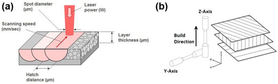
Figure 1.
Main parameters and axes in SLM process: (a) parameters denoted in one layer and (b) axes, build direction, and scan pattern strategy used for layers in SLM samples.
For this study, the laser power was 212.5 W, and the applied preheating temperature on the build platform was 170 °C, which was selected to minimize the residual stresses with thermal origin, reducing in turn the geometric distortions in the printed part and the need for a greater thermal input for the selective melting of the particles. This also promotes the characteristic fine microstructure obtained and contributes to achieve the best mechanical properties in the as-built condition. The parts were manufactured using a Renishaw RenAM 500Q Selective Laser Melting system. This machine is equipped with four Ytterbium fiber lasers (IPG Photonics, Oxford, MA, USA) of 500 W each, working in continuous wave operation mode. The laser beams were focused to a diameter of around 80 µm with a Gaussian shape and the build chamber operates with a protective atmosphere, with 0.2% being the maximum oxygen allowable during manufacturing of the parts. A linear stripe scan strategy was used with stripe rotation of 67° between layers, and argon was used as protection gas. For tensile tests, cylindrical samples (12 mm diameter and 105 mm height) were manufactured on the “Z-axis” (or build direction) and on the “Y-axis” (or perpendicular to build direction), as indicated in Figure 1b, employing the optimum processing parameters determined following the methodology explained in Section 3.2, with the aim of obtaining samples with minimum porosity level, free of defects, and with adequate surface quality. Two build platforms, similar to the one shown in Figure 2, were necessary to produce the samples used in this study.
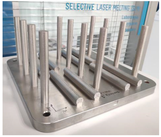
Figure 2.
View of cylindrical samples obtained from SLM process. “Z-axis” samples (left, center and on the right of the platform) and “Y-axis” samples (interspersed with vertical specimens).
The investment casting process was done in an industrial environment, in the casting facilities of Eibar Precision Casting (EIPC) located in Eibar, Gipuzkoa, Spain. A wax structure with 20 rectangular block samples (50 mm width, 10 mm thick, and 100 mm large) was produced (Figure 3a). The wax structure was shell-coated with ceramic slurry composed of three primary layers and five backup layers to obtain the mould (Figure 3b); afterwards, the mould was dewaxed in an autoclave to obtain the final mould in which the casting was made. Ingots of Inconel 718 alloy were used for the casting, and the measured chemical composition is shown in the first row of Table 2. For comparison, the chemical composition of the raw material in samples from SLM and for investment casting processes were measured again, in order to evaluate differences in their composition and to check for potential evaporation of some elements. Obtained results are compiled in Table 2.It can be observed that no major differences were detected in the IN718 Powder and SLM samples.
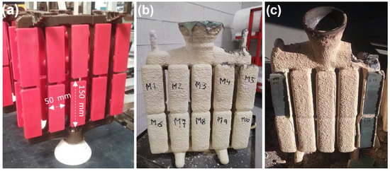
Figure 3.
View of the mould and block samples obtained from investment casting process in IN718. (a) Mould in wax, (b) mould with shell after cast, and (c) mould without shell with integrated casts.
Table 2.
Chemical composition measured in the raw materials and in the manufactured samples.
The differences in chemical composition in the raw material used for the two manufacturing routes are due to the fact that a higher content of Si is required as a grain refiner for the investment casting process and lower content of Cr is needed for fluidity of liquid metal; the rest of the alloy elements are in a similar proportion.
The relative density in SLM as-built samples was measured by image analysis after using an Olympus GX51 optical microscope. Five images of the worst areas in the cross-section of the sample at 100X magnification were taken for the analysis. Manufactured samples obtained by SLM and investment casting processes were heat treated through three combinations of homogenization, solution, and double aging thermal treatments in a high-vacuum furnace. The first heat treatment studied was the standard one; the specific conditions of each stage are defined by standards such as AMS 2774F [14], which apply to wrought or additively manufactured materials for use in primary structural components. Another reference standard is the AMS 5383F standard [15], used for the heat treatment of investment casting components with this alloy. The homogenization and solution stages must be carried out in a high vacuum furnace to avoid oxidation and to obtain clean and unalterable surfaces in terms of chemical composition and therefore obtain fully finished parts after heat treatment (in real applications). For all treatments a heating rate of 10 °C/min and minimum vacuum level of 5 × 10⁻³ mbar was applied, and the specific conditions for each stage of the heat treatments (standard and tailored/modified) are detailed in Table 3. The specific conditions (temperature and time) for the solution stage in TT1 were selected considering their potential impact on the microstructure and mechanical properties of SLM samples. Partial recrystallization appears over 1130 °C, and the original dendritic microstructure could be replaced by recrystallized grains in some regions [16]. It is not desirable to prolong solution stage 2 beyond 2 h (coarsening of microstructure). In fact, other authors also reported a considerable volume (>50%) of recrystallization after annealing SLM-fabricated specimen at 1160 °C for 4 h [12].
Table 3.
Conditions for solid homogenization, solution, and artificial aging heat treatments.
The reference conditions for each stage were taken from those defined for the standard heat treatment (TT0), and considering the fine dendritic microstructure obtained in as-built (SLM) with the pre-heating and process parameters used, the homogenization stage was removed, and the temperature and time of solution stage were reduced and increased respectively in the TT1. For TT2, the aim was to study only direct aging of the samples. In summary, for the double-stepped aging stage, same conditions of the standard heat treatment were used for all heat treatments in order to compare potential improvements in the precipitation hardening mechanisms between the different combinations of heat-treatment stages but keeping the double-stepped aging condition.
For microstructural evaluation, the samples were cut from tensile coupons and conventional metallographic preparations were made, embedding the samples in resin to then carry out a roughing with abrasive papers with different granulometry, and a final polishing with diamond particles in suspension. Manual chemical etching (for SLM samples only) was carried out with Kalling Nº 2 reagent for 12 s. The first observations were made on an Olympus GX71 light optical microscope with an image acquisition system via digital camera. The micrographs were evaluated at different magnifications (100X, 200X and 500X). For advanced microstructural evaluation, a Zeiss Ultra Plus FESEM microscope equipped with X-Max Oxford Instruments system and x-ray silicon drift detector (SDD) of 20 mm2 was used to acquire high magnification micrographs (5000X to 25,000X) and to perform semi-quantitative analysis of the chemical composition by energy dispersive spectroscopy (EDS). Finally, X-Ray Diffraction (XRD) analysis was used to identify the crystallographic phases and their evolution with the heat treatments. The XRD was performed on a Philips X’Pert machine using monochromatic Cu–Kα radiation (λ = 0.15406 nm). The XRD patterns were obtained in the range of 2θ from 20 to 90° and were analyzed using X’Pert Plus software (PANalytical).
Tensile tests and hardness measurements of all samples (as-built/as-cast and heat-treated) were performed in a Zwick Roell Z100 testing machine and in an EmcoTest DuraScan durometer, respectively. To conduct the uniaxial tensile tests, a nominal capacity of 100 kN and a test speed of 0.0005–500 mm/min were used. In addition, it is equipped with an extensometer with elongation to break reading, extensible arms up to 300 mm, and a calibrated length range (Lo) from 10 to 100 mm. All tensile test samples were machined before the test with rounded sub-size geometry according to the ASTM E8M guidelines and in correspondence with UNE-EN ISO 6892-1 standards.
Vickers hardness was measured on the transversal section of the tensile samples’ heads. The measurements were carried out according to the UNE-EN ISO 6507-1 standard. The scale applied was HV0.5 (Load 0.5 kgf and time 15 s) and nine measurements were made in each sample, in the cross section of the sample (Ø10 mm), in a matrix of measurements separated from each other at 1.75 mm, and even 1.5 mm from each of the ends or edges fixed by the diameter.
In the present work, a total of 48 uniaxial tensile tests were carried out, 4 samples per condition and 12 different conditions were studied, and the mean value and deviation were calculated from the results obtained in four tests for each condition/process. Among those, samples were manufactured by investment casting, SLM Y Axis and Z Axis, and for each of those conditions four different heat treatment conditions were used (as-cast/as-built, TT0, TT1 and TT2).
3. Results
3.1. Powder Characterization
The pre-alloyed IN718 alloy powder used in this work showed a spherical morphology (Figure 4a), typical of the gas atomization process. After particle size distribution analysis, the results revealed that a cumulative 10% mass-volume of the particles had a smaller diameter than 17.7 microns for the powder; 50% of the particles were smaller than 23.5 microns; and a cumulative 90% mass-volume of the powder particles had a smaller diameter than 31.1 microns. Particle shape and size distribution (diameter) analysis of the powder shown in Figure 4b is very important for the SLM process. Due to the typical recoater system used in powder bed fusion machines, fine granulometry and regular sizes and shapes are required, and an adequate flowability of the powder determines the best packing of particles in the powder bed layer before the laser melting.
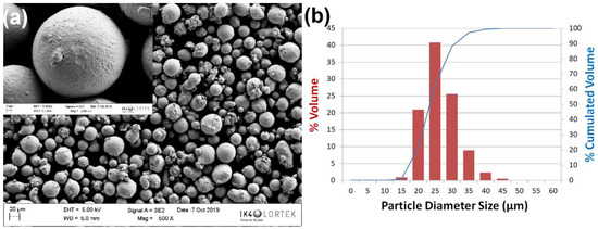
Figure 4.
IN718 pre-alloyed powder. (a) Morphology of the particles in SEM image (20 kV) and (b) granulometry and distribution analysis.
Flowability is another important aspect in SLM processing. As mentioned before, the recoater systems requires particles to flow properly for an adequate distribution of the powder bed in the machines, and to achieve suitable packing (due to different particles size and its morphology) and ensure a certain layer thickness, which may influence the lack of fusion and other relevant defects after laser processing. The IN718 pre-alloyed powder selected in this work has sufficient flowability (18.74 ± 0.25 s/50 g) measured at 22 °C according to ASTM B213-17 Method 1 [17]. On the other hand, the measurement of apparent density provides information on possible internal porosities of the material, as well as its adequate packing, which is also associated with the morphology and size of the particles.
Internal porosity in the cross-section of powder particles was also evaluated. The results of the porosity measurements show a low percentage of internal porosity: 0.10 ± 0.12%, which results in a particles densification of 99.9 ± 0.12%. This is positive, since according to various authors [18,19,20,21], the internal porosity of pre-alloyed nickel-based powders is revealed later, after rapid solidification, as gas trapped in SLM-manufactured parts. Since a lower internal porosity of the particles translates to a greater apparent density (without considering the morphology of the powder and its influence on the packing of the particles during the measurement of apparent density), a starting powder with the lowest internal porosity possible is desirable to minimize the presence of pores after solidification in laser melting. The results obtained from internal porosity are also related to the measured apparent density (4.18 ± 0.01 g/cc3) with the method defined in the ISO 3923-1 standard and using the Hall flowmeter funnel. In Figure 5, images of internal porosity analysis (Figure 5a) as well as EDS microanalysis with the chemical composition of particles analyzed for this powder (Figure 5b), which confirms the composition of IN718 alloy (AMS 5383F), can be observed.
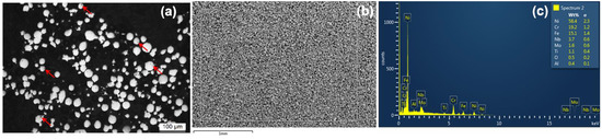
Figure 5.
IN718 pre-alloyed powder. (a) OM micrographs of particle cross-sections (200X) arrows indicate the porosities revealed. (b) FESEM of powder particles, and (c) Measurements of chemical composition by EDS (1000X, 20 kV, Mode SE).
3.2. Selective Laser Melting Process
The SLM processing parameters window can become wide, since the preliminary optimization can be done for the hatch (or core) on the part, as well as for the definition of the edge/contour of each layer (affecting the tolerances and final surface finish). However, after initial trials with a design of experiments (DoE) composed of three hatch distances (0.07, 0.09, and 0.11 mm), two laser powers (217.5 and 240 W), and four different scanning speeds (650, 750, 850, and 950 mm/s), the rest of the parameters were constant: preheating temperature of 170 °C, laser spot diameter at focal point of 80 µm, and a layer thickness of 60 µm in order to obtain the best balance between surface finish, process time, and resolution. Recently published studies conclude that a combination of 200–285 W and a scanning speed of 960–1000 mm/s generates good material densification [22] and the best mechanical properties in IN718 samples obtained by SLM [23]. In our work, a similar trend was evidenced, and good results in the densification of the material were achieved. Figure 6 shows the evolution of the resulting material density in the hatch of cuboids (10 × 10 × 10 mm3) manufactured with the different scanning speeds and hatch distances derived from the DoE. As it can be observed, material densification is higher for higher scanning speed values. In the same way, for higher scanning speed—as well as constant power, hatch distance, and layer thickness—energy density is also lower (see Equation (1)), which reduces the number of pores that appear due to gas trapped during solidification and its vaporization during melting; it is associated to internal porosity and humidity in the powder particles. After evaluating these results, a set of process parameters for IN718 alloy was selected. In Figure 7, we can see that low densification (mainly due to gas-trapped and small lack of fusion in the material) occurred for high laser energy densities (above 65 J/mm3) combining high laser power with lower speeds. The best results in terms of material densification were achieved using the lowest laser power value considered (212.5 W) and energy density between 35–60 J/mm3, obtaining material densities greater than 99.95%. The final combination selected was a hatch distance of 0.11 mm and a scanning speed of 850 mm/s, resulting in an energy density of 37.9 J/mm3 and obtaining a material density of 99.97 ± 0.01%. Other authors such as Choi et al. [24] and Hakeem et al. [25] reported density values of 99.70% with 60–150 J/mm3 and 99.50% with 50–70 J/mm3, respectively, which are lower densification values than the one obtained in this work. It is interesting to highlight that the energy density used for the best densified sample is lower than the range explored in the mentioned works. Finally, the parameters for the contour were also optimized using a focus offset in the fill contour, taking as a criterion not only the greatest densification, but also the smallest deviation of the edge’s surface, which will generate a better surface roughness in complex geometries.
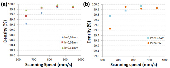
Figure 6.
Evolution of material density as a function of scanning speeds for different hatch distance and laser power. (a) Material density for 212.5 W, and (b) density evolution using 0.11 mm hatch distance.
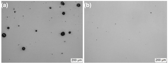
Figure 7.
Micrographs of the cross-section of SLM cuboids with different process parameters. (a) power: 240 W, speed: 650 mm/s, and hatch distance of 0.09 mm. (b) power: 212.5 W, speed: 850 mm/s, and hatch distance of 0.11 mm.
3.3. Investment Casting Process
The investment casting process was carried out in an industrial environment using the facilities of the company Eibar Precision Casting (EIPC). The wax patterns were injected in a vertical machine at 65 °C. Then, the patterns were mounted in a recycled wax structure as previously shown on the left of Figure 3. Afterwards, the wax structure was shell coated using robotic equipment with the following materials:
- For primary coatings, a slurry made of colloidal silica binder and zircon flour was used. Then, the mould was stuccoed with zircon sand.
- For secondary coatings, a slurry made of colloidal silica binder and silica flour was used. Then, the mould was stuccoed with silica sand.
Once the mould was dry, it was dewaxed in an autoclave with water vapor at 150 °C and a pressure of 9 bar. Then, the mould was fired and preheated at 1150 °C prior to the casting, whereas the molten material was poured at 1450 °C. Both the IN718 melting and the pouring processes were carried out under vacuum atmosphere. The mould was then taken out from the vacuum furnace and cooled down at room temperature. The knockout and sample cleaning operations were then carried out to obtain parts ready for thermal treatment and subsequent machining post-processing.
4. Discussion
4.1. Comparison of Microstructures
In the SLM process, micrographs cross section with horizontal orientation (Y axis) and build direction (Z axis) are shown. In the samples manufactured by SLM in as built condition, both in the Y-axis and the Z-axis samples (Figure 8) a very fine cellular microstructure typical of selective laser melting processes is observed, due to the rapid solidification of fast laser material processing [2,11,12,26] and because of the high cooling rate (105 to 107 k/s) during the SLM process [24]. Columnar and cellular sub-structures formed in the overlapping area (where re-melting occurs) are observed, while mainly cellular sub-structures are present in the area of fusion inside the tracks.
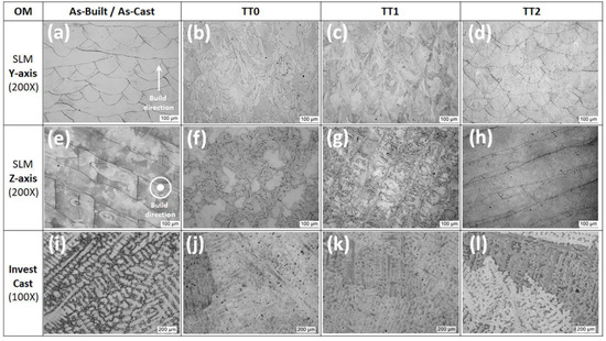
Figure 8.
Optical micrographs for IN718 in as-built/as-cast and heat-treated condition. (a–d) SLM samples in Y-axis, (e–h) SLM samples in Z-axis, and (i–l) Investment casting samples. (SLM samples are etched with Kalling Nº2 and investment casting samples only polished).
The micrographs of Y axis samples (Figure 8a) show the cross section of the melt pool tracks in the successive passes of the laser beam during layer-by-layer manufacturing. In the cross section of the SLM samples manufactured in vertical orientation (Z axis of the machine) shown in Figure 8e, the top view of the melt pool tracks in the successive passes of the laser beam during the manufacturing of one or two layers (cross section not exactly on one layer) is observed. The scanning strategy used (stripes with 67° rotation in each layer) generates the direction changes observed in the laser beam trajectories. There are fewer re-melted and thermally affected areas in the XZ plane, Figure 8a, than in the XY plane. The differences observed in the microstructure (and also in their crystallography) on each direction can directly affect the mechanical properties (anisotropy) that metal alloys obtained by SLM usually present in their delivery state (as-built condition). In samples manufactured in both orientations, a low level of porosity can be observed.
The microstructure of the samples manufactured in both orientations is similar with the only difference in the orientation of the grains and the re-melted and thermally affected areas; therefore, FESEM images are shown only on the Y axis (Figure 9). The microstructure of these specimens is characterized by a very thin cell structure, with a dendrite arm spacing of less than 1 µm and a fine precipitation in the grain borders (See Figure 9a,e). These precipitates are rich in Niobium. According to Deng et al. [27] and Popovich et al. [28], they are Laves precipitates. The formation and precipitation of Laves phase reduces the Niobium content available for the constitution of γ′ and γ″ precipitates [11,16,26,27], so it is important to control their formation to allow the adequate strengthening and subsequent achievable mechanical resistance in the material.
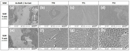
Figure 9.
FESEM micrographs at different magnifications for IN718 SLMed in as-built and heat-treated conditions. (a–d) SLM samples in Y-axis, and (e–h) SLM samples in Z-axis. (all samples etched with Kalling Nº2).
The microstructure observed in the samples manufactured by investment casting in as-cast-condition (Figure 10) is very different to that seen in as-built SLMed parts. Investment casting samples in as-cast condition show a dendritic structure with an average spacing of the secondary dendritic arms of approximately 50 µm; this is the typical casting microstructure for IN718 alloy obtained with slow solidification speed [25]. The microstructure is constituted by gamma nickel matrix, large Laves (rich in Nb and Mo), and delta phases of irregular segregation in the interdendritic zones (see Figure 10), which is a similar microstructure to that reported by other authors [6]. The segregation of Nb and Mo during the casting process produces a heterogeneity of these elements and during solidification the laves and delta phases are formed in the dendrites [25]. Titanium nitrides were also detected in specific zones.
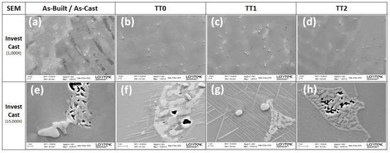
Figure 10.
FESEM micrographs for IN718 investment casting in As-cast and heat-treated conditions. (a–d) Investment casting samples at low magnification, and (e–h) Investment casting samples at high magnification. (samples not etched, only polished).
When applying the AMS standard heat treatment (TT0) in the SLM samples, the cellular structure observed in as-built condition disappears and grain growth is observed due to the homogenization step of the heat treatment, as can be seen in Figure 9b,f. The microstructure analysis reveals bigger phases distributed in grain boundaries (see Figure 11). These phases, according to their morphology and chemical composition, correspond to delta phases in two morphologies: short-rod and needle shape, and Laves phases, which were not dissolved in the homogenization step [29]. The presence of small sub-micrometric γ′ and γ″ precipitates in the gamma nickel matrix can be appreciated although they are not clearly distinguished due to their small size (nanometric range).
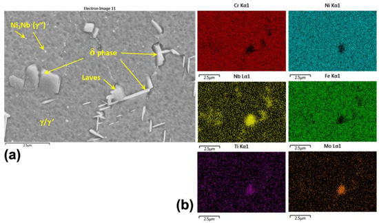
Figure 11.
FESEM micrograph for IN718 alloy with standard heat treatment—TT0 (polished sample, SE mode). (a) SLM Y-axis sample and (b) the respective x-ray elemental maps through EDS.
In the homogenization step it is possible to dissolve a large part of the Laves phases and due to the high temperature of this step, also Nb diffuses in the matrix, achieving precipitation of the delta phase during the subsequent solution stage when these phases are formed at the grain boundaries. Previous research works [2,30] reported that with a homogenization step at 1080 °C a uniform distribution of Nb is achieved, minimizing acicular δ phase precipitation during the solution stage. Delta phase precipitates at temperatures between 650 °C and 980 °C [31], so it does not precipitate during the homogenization stage but could do it in the following stages of the thermal treatment. This precipitation is mainly needle-shaped and located on the grain edges. These precipitates have been observed to prevent grain growth and dislocation sliding mechanism during high temperature exposure in IN718 alloy [2,25,32].
In the case of the samples manufactured by investment casting, it is observed that the dendritic microstructure is more globular and the dissolution of the segregated phases occurred to a great extent but not completely, since some remaining Laves phases are observed and still remain in the microstructure (Figure 9b,f). The homogenization stage of the microstructure is very important in the investment casting processing route to dissolve these undesirable phases and to enhance the precipitation of gamma prime and double gamma phases that reinforce the matrix of this material [33,34]. Laves phase and possible delta phase are also observed with the shapes of needles thus irregularly shaped, but always at the edges of the grain or in the vicinity of it (Figure 12), as in the sample manufactured by the SLM process.
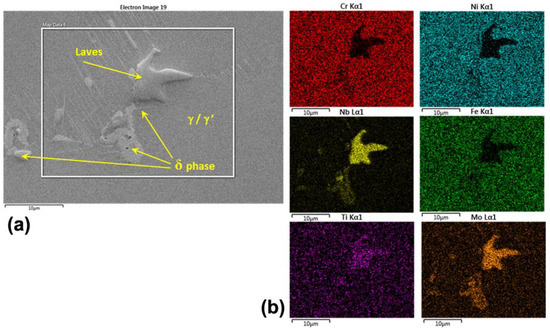
Figure 12.
FESEM micrographs for IN718 alloy obtained by investment casting. (a) with standard heat treatment—TT0 (polished sample). (b) the respective x-ray elemental maps through EDS.
By eliminating the homogenization stage, in the so-called modified heat treatment (TT1), a finer structure with smaller Laves and delta phases with a uniform distribution was achieved in the case of SLM. This is due to the fact that, without the homogenization stage, these phases do not dissolve. It is also appreciated that there is a higher delta phase density but smaller size that could have formed, particularly for this heat treatment.
Previously, it was observed that the solution treatment at 980 °C for 1 h without homogenization stage was not sufficient to dissolve Laves phases present in the as-built microstructure of SLM samples [2]. In addition, with the temperature being too low, there is not enough driving force for Nb to diffuse and homogenize its concentration throughout the gamma matrix, since this element easily segregates at the grain borders and interdendritic regions, enhancing the formation of Laves (10–12 wt.% of Nb) and delta (6–8 wt.% of Nb) phases. Due to this dissolution and diffusion phase, the delta phase precipitates in the interdendritic regions and grain borders in the TT1 both in acicular and needle-like form (Figure 13), in addition to remaining Laves phase that did not dissolve [30].
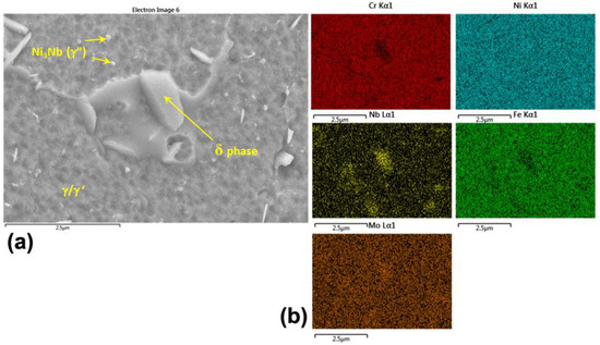
Figure 13.
FESEM micrograph for IN718 alloy with modified heat treatments (polished samples, (a) Y-axis sample with TT1 (25,000X, left), and (b) the respective X-ray elemental maps through EDS (right).
Other research works suggest eliminating the solution step and carrying out a homogenization and double aging treatment, thus avoiding, to a great extent, the precipitation of the delta phase [10]. The delta phase is a detrimental phase on the mechanical properties for two reasons: First, it consumes the Nb content, reducing the potential for precipitation of γ′ and γ″, and second, the Laves phases are starting points for crack propagation, affecting their structural integrity [32] and accelerating the failure in service.
In the case of investment casting, the dissolution of the phases that were in the interdendritic regions was not achieved and the traces of dendrites but with smaller interdendritic arms compared to the as-cast sample were observed. Laves phases of greater size than those observed after the application of the standard treatment, appeared; in addition, titanium nitrides were observed together with these phases, as shown in Figure 14.
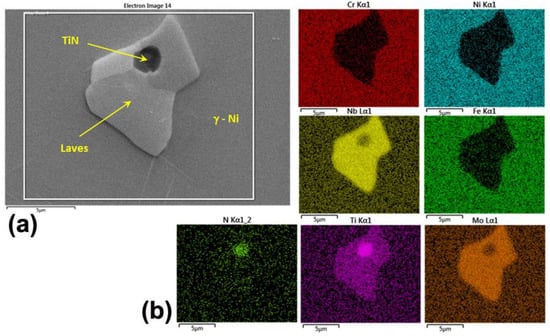
Figure 14.
FESEM micrograph for IN718 alloy obtained by investment casting. (a) with modified heat treatment—TT1 (polished samples, SE mode), and (b) the respective X-ray elemental maps through EDS.
After the double-stage aging heat treatment (direct aging, TT2), tracks and cellular structures (similar to the ones found in as-built condition) were observed in the cross-section of the SLM samples, not achieving a coarsening of the microstructure. The direct double aging applied to the SLM samples does not substantially modify the fine dendritic structure obtained after processing (compared to the as-built condition observed in Figure 9d). In addition to the hardening effect of the fine delta phase particles in the interdendritic zones, the potential effect of phase precipitation could be in the gamma nickel matrix itself. The presence of these precipitates can be intuited, but they are too small (nanometric scale) to be correctly identified in FESEM micrographs. Small Cx-type carbides and small titanium nitrides are also present in the TT2 microstructure (Figure 9h).
The investment casting samples treated with only the stepped aging stage present a very similar microstructure to that observed in the as-cast samples without heat treatment (Figure 10a), but with a smaller size of dendritic arms, where there are large delta phase islands, accompanied in some areas, by irregularly shaped particles (Laves phase), formed after solidification (Figure 10h).
4.2. Phase Identification and Evolution—XRD Analysis
To study the crystallographic phase’s presence in the as-built/as-cast conditions and their evolution with the heat treatments, a XRD analysis was performed. Figure 15 shows the diffraction pattern obtained for the different conditions. In the pre-alloyed powder used for the SLM process, the principal phases are gamma and/or gamma prime: γ-Ni(Fe,Cr) and/or γ′-Ni3(Al,Ti). Similar phases are detected both in SLM and investment casting samples, since γ/γ′/γ″ have similar crystallography according to the peak intensity for each phase. Phase detection in XRD technique has limits: Only crystallites larger than 10 nm are detected [35] and it usually fails to recognize phases present at less than 5% of mass fraction in the specimen. The existence of γ″ is not well detected in the XRD pattern due the overlapping of their peaks with γ/γ′. There are no evident peaks for delta and Laves phases, perhaps due to their low volumetric fraction in the alloys obtained with both manufacturing processes, but strong <111> and <200> diffraction peaks for γ/γ′are observed in all the conditions studied, and it is consistent with XRD patterns reported for IN718 SLMed samples by some authors [25,30,32,36].
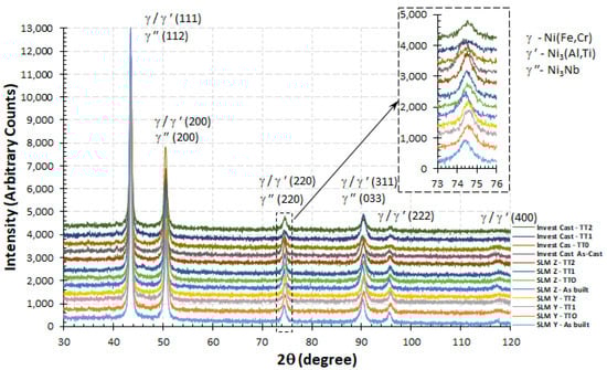
Figure 15.
X—Ray diffraction patterns of IN718 powder, SLM, and investment casting samples.
Li X. et al. [32] also detected the presence of delta <211> diffraction peak in SLM samples manufactured with IN718 and direct aged, but no peak was detected in the as-built condition, which leads us to think that the temperatures used by them in the double stepped aging stage (higher than those used in this work) promoted the formation/modification of the delta phase in detriment of the precipitation of strengthening phases (γ′/γ″), which are not the desired precipitation kinetics for the SLM processing. In this XRD analysis, the presence of delta and lave phases was not detected in the patterns for the different conditions studied.
A slight shift to the left is noticed in the peaks of the as-built/as-cast samples, which is more evident in peaks <220> and <311> for γ/γ′, and this shows that there is indeed a change in the crystallography of the present phases, and the only possibility is the potential dissolution of the minority delta and Laves phases (in the case of TT0 and TT1) and subsequent precipitation of the strengthening phases of these alloys (in the TT0, TT1, and TT2 heat treatments).
4.3. Comparison of Mechanical Properties
For the testing of mechanical properties, cylinders (in the case of SLM) and rectangular plates (in the case of investment casting) were manufactured, from which cylindrical tensile samples were obtained after cutting, machining, and turning. As for SLM samples, they were manufactured in two different orientations, horizontal (Y axis) and vertical (Z axis). The aforementioned heat treatments (Table 3) were applied to both samples manufactured by means of SLM and investment casting, so that four samples of each condition were tested. After performing tensile tests, some sections of the samples were cut to measure the micro hardness of the material.
The summary of results obtained from the tensile tests for SLM samples is shown in Table 4. The results were calculated as the mean value of three tests performed (out of four). The value obtained in the fourth test was taken into account because of different reasons, such as problems during the test itself (jaw slips or extensometer displacement) and/or big deviations in results compared to other samples tested in the same condition.
Table 4.
Summary of mechanical properties for IN718 alloy obtained by SLM.
Figure 16 shows the high strength that was obtained in the IN718 Alloy with the SLM process; in particular, in the as-built condition, the mechanical properties obtained for the horizontal and vertical samples are slightly higher than those reported by some other authors. For instance, Li et al. [37] reported as-built yield strength and UTS values of 590 ± 5 MPa and 935 ± 16 MPa respectively. In the case of Zhang et al. [30], results obtained in this work are below the ones reported. On the other hand, anisotropy is observed between the SLM samples manufactured with vertical and horizontal disposition for this condition, reaching differences in as-built condition of around 5.3% in the maximum resistance, 18.3% in the yield strength, and 3.3% in the elongation until rupture. The horizontal samples (Y-axis) were those that presented the highest resistance with the lowest ductility. Although it is noteworthy that a low variability in the results was evidenced for this condition, this is reflected in the reported standard deviation of the results. It is worth mentioning that heat-treated SLM tensile samples showed a dimpled surface at fracture, indicating a transgranular ductile failure mode as previously reported by Zhang D. et al. [10].
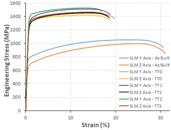
Figure 16.
Engineering stress–strain curves for SLM samples in different conditions.
When comparing the mechanical properties obtained between the heat-treated SLM and investment casting samples, it can be observed that the SLM samples exceed the mechanical resistance obtained in the investment casting samples with standard heat treatment, and adequate ductility is also obtained in all the conditions studied. Comparing the best results obtained in SLM (Y Axis—TT2) with the best results obtained for investment casting samples (TT0), there is a 51.3% increase in maximum resistance, with a 66.2% higher yield strength and also a slight increase in the elongation at break of 0.5%. These results indicate that the expected hardening was achieved through the strengthening mechanisms by precipitation and dispersion of particles (solid solution), which are sought with the combination of putting into solution and artificial aging in the standard TT0, taking into account that both IN718 alloys have similar chemical composition in both manufacturing routes studied. This can be seen graphically in the comparison between all the conditions and processes shown in Figure 17, where yield strength (σy), ultimate tensile strength (UTS), elastic modulus (E), and the percentage of elongation at break (ε) are represented.
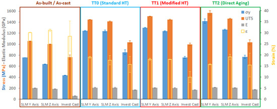
Figure 17.
Evolution of mechanical properties with heat treatments for IN718 alloy.
Besides, results reported by other authors for SLMed IN718 samples with similar heat treatments to those applied in this work are lower. Table 5 shows a comparison of the measured properties of as built and heat-treated samples with those reported in the literature.
Table 5.
Summary of mechanical properties for SLM IN718 alloy in this work compared to other authors.
These results allow us to confirm what was concluded in the microstructural analysis by means of optical microscopy and FESEM examination: that the first two stages of the standard treatment (homogenization and solution) are not completely necessary in the IN718 alloy obtained by SLM to improve its mechanical properties, which were obtained in as-built condition, due to the fine and homogeneous cellular microstructure with small and well distributed Laves and delta phases at the grain boundaries that originated after SLM processing, which contribute to obtain better mechanical properties including a reasonable ductility (even higher than that obtained in investment casting with TT0). The influence of delta phase on the mechanical properties is well known in this alloy [31,39,40]. Improved mechanical properties were obtained by applying only a stepped direct aging to SLM samples. This thermal treatment allows, in addition, the refining of delta phase in a needle-like shape in the interdendritic regions, and the precipitation of γ′ and γ″ in the matrix, improving the mechanical properties obtained in the as-built condition. A similar trend of improving mechanical resistance with direct double aging of IN718 SLMed samples was reported recently by Teng Q. et al. [41].
Table 6 shows the summary results obtained in the tensile tests performed on those samples manufactured by means of investment casting. In all cases, the mechanical resistance and even the ductility are lower than those obtained with the SLM process with the same heat treatments.
Table 6.
Summary of mechanical properties for IN718 alloy obtained by investment casting.
Investment casting samples in as-cast state presented low resistance and ductility, which improved significantly with the application of the standard TT0 heat treatment, increasing their maximum resistance by 35.5%, their elastic limit by 96.8%, and reducing their elongation at break by 81.5%. As a reference, Figure 18 shows the stress–strain (elongation) of a representative test sample for each condition. Comparing the stress–strain curves of both SLM and investment casting samples (Figure 16 and Figure 18 respectively), an appreciable difference between the elasto-plastic behavior of the IN718 samples obtained by both processes can be seen in the as-manufactured state and after the application of different heat treatments.
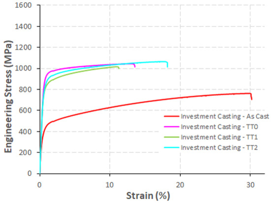
Figure 18.
Engineering stress–strain curves for investment casting samples in different conditions.
Hardness measurements were carried out according to the UNE-EN ISO 6507-1 standard to complete the analysis of the mechanical properties. From these measurements, the average and standard deviation of the measurements were calculated, which are compiled in Table 7.
Table 7.
Hardness values obtained for analyzed conditions.
When comparing the values obtained for the different conditions, a similar trend to that seen in the evaluation of mechanical properties with the tensile tests is observed. The bar graph in Figure 19 shows the comparison between the IN718 samples obtained by SLM and the investment casting samples. Comparing samples in the same heat treatment stage, it can be concluded that in all cases, SLM samples achieve higher hardness values than investment casting ones. The SLM samples with TT2 present approximately 26.3% more hardness than the investment casting samples with TT0, which confirms that the hardening by dispersion of γ′/γ″ particles (solid solution) in the γ nickel matrix allows to slightly improve the mechanical properties after its SLM processing, applying only stepped direct aging.
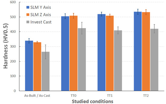
Figure 19.
Hardness evolution for SLM and investment casting samples in different conditions.
Comparing the hardness values obtained in this work with results reported by other authors, it can be concluded that for similar heat treatments (with small differences in the temperature and times for each stage), higher hardness of the material was achieved with the process parameters and manufacturing route used. Table 8 shows the comparison of HRC hardness values reported by other authors and with the results obtained in this work.
Table 8.
Summary of hardness values (HRC) obtained in this work (mean values converted from HV0.5 measurements on SLM Y-axis samples) compared to other authors.
5. Conclusions
After comparing as-built/as-cast and heat-treated microstructures, both manufacturing routes (SLM and investment casting) generate quite different microstructures. The main conclusions on this aspect are:
- Due to the differences in cooling rates between investment casting and SLM process, the microstructures generated are completely different. While the one obtained by investment casting is composed mainly by a dendritic structure, the one obtained by SLM is characterized by columnar and cellular structures with a very thin cells microstructure.
- The employment of the homogenization stage in the thermal treatment allows to achieve the solubilization of undesired phases, which is not the case with the solution stage.
- The double aging treatment at stepped temperatures carried out in the present work assures the precipitation of γ′ and γ″ to improve the mechanical properties obtained in as-built/as-cast conditions for the IN718 alloy.
After comparing the mechanical properties obtained in both processes, the strength of SLM samples in as-built and direct-aged conditions exceeds the strength obtained in investment casting heat treated (TT0), and the ductility measured in SLM samples through elongation at rupture is satisfactory for both orientations evaluated, since it exceeds the typical values required for aeronautical parts obtained by investment casting, although this depends partly on the customer and final application. Related to this, the improved mechanical properties obtained in the IN718 alloy processed by SLM are mainly affected by:
- The dispersion of γ′/γ″ particles (solid solution) in the γ-Ni matrix and the presence of a small quantity of delta phases in the interdendritic regions, which allows to improve the mechanical properties of the material after its SLM processing.
- Due to the fine and relative homogeneous microstructure obtained from SLM processing of IN718 alloy, it is not necessary to apply homogenization and solution stages as in the standard heat treatment used for this type of alloy obtained by casting or wrought. The pre-heating and process parameters selected, in combination with direct-stepped aging heat treatment (at 720 °C/620 °C), provides the material obtained by SLM with its best mechanical properties.
The SLM process generates a material with adequate strength in as-built condition compared with the standard heat-treated investment casting IN718 alloy, and the ductility and hardness are slightly improved with the only application of a direct double-aging treatment after its manufacture, which does not require the solubilization phase (solution) commonly used in the standard treatment and widely used in the foundry industry, to achieve high strength. Apart from the delta phase observed in as-built condition in SLM, other strengthening mechanisms were found: A combination of solid solutions with fine precipitation of strengthening phases in the matrix.
Author Contributions
Conceptualization, J.C.P. and P.P.R.; methodology, J.C.P. and J.A.; validation, J.C.P. and P.P.R.; formal analysis, J.C.P., N.R., J.A., M.C.T.; resources, J.C.P. and P.P.R.; data curation, J.A. and N.R.; writing—original draft preparation, J.C.P.; writing—review and editing, M.C.T. and J.C.P.; project administration, J.C.P.; funding acquisition, P.P.R. All authors have read and agreed to the published version of the manuscript.
Funding
This research was funded by the Basque Government grant KK-2019/00007 (Departamento de Desarrollo Económico e Infraestructuras del Gobierno Vasco, Programa ELKARTEK Convocatoria 2019) through OPTIFAN project.
Institutional Review Board Statement
Not applicable.
Informed Consent Statement
Not applicable.
Data Availability Statement
The data presented in this study are available on request from the corresponding author. The data are not publicly available due to confidential non-disclosure agreement.
Acknowledgments
The authors would like to thank the Institute of Materials Technology (ITM) of the Universitat Politècnica de València (UPV)—Spain and especially Vicente Amigó for the DRX analysis made.
Conflicts of Interest
The authors declare no conflict of interest.
References
- Sun, S.-H.; Koizumi, Y.; Saito, T.; Yamanaka, K.; Li, Y.-P.; Cui, Y.; Chiba, A. Electron beam additive manufacturing of Inconel 718 alloy rods: Impact of build direction on microstructure and high-temperature tensile properties. Addit. Manuf. 2018, 23, 457–470. [Google Scholar] [CrossRef]
- Hosseini, E.; Popovich, V.A. A review of mechanical properties of additively manufactured Inconel 718. Addit. Manuf. 2019, 30, 100877. [Google Scholar] [CrossRef]
- Ghiban, B.; Elefterie, C.F.; Guragata, C.; Bran, D. Requirements of Inconel 718 alloy for aeronautical applications. AIP Conf. Proc. 2018, 1932, 30016. [Google Scholar] [CrossRef]
- Zhang, B.; Wang, P.; Chew, Y.; Wen, Y.; Zhang, M.; Wang, P.; Bi, G.; Wei, J. Mechanical properties and microstructure evolution of selective laser melting Inconel 718 along building direction and sectional dimension. Mater. Sci. Eng. A 2020, 794, 139941. [Google Scholar] [CrossRef]
- Godec, M.; Malej, S.; Feizpour, D.; Donik, Č.; Balažic, M.; Klobčar, D.; Pambaguian, L.; Conradi, M.; Kocijan, A. Hybrid additive manufacturing of Inconel 718 for future space applications. Mater. Charact. 2021, 172, 110842. [Google Scholar] [CrossRef]
- AM-Motion. A Strategic Approach to increasing Europe’s Value Proposition forAdditive Manufacturing Technologies and Capabilities. 2018. Available online: https://ec.europa.eu/research/participants/documents/downloadPublic?documentIds=080166e5bf8b8d98&appId=PPGMS (accessed on 7 June 2021).
- McCue, T. Significant 3D Printing Forecast Surges to $35.6 Billion. Available online: https://www.forbes.com/sites/tjmccue/2019/03/27/wohlers-report-2019-forecasts-35-6-billion-in-3d-printing-industry-growth-by-2024/ (accessed on 25 September 2019).
- Wang, P.; Song, J.; Nai, M.L.S.; Wei, J. Experimental analysis of additively manufactured component and design guidelines for lightweight structures: A case study using electron beam melting. Addit. Manuf. 2020, 33, 101088. [Google Scholar] [CrossRef]
- Wang, P.; Li, X.; Luo, S.; Nai, M.L.S.; Ding, J.; Wei, J. Additively manufactured heterogeneously porous metallic bone with biostructural functions and bone-like mechanical properties. J. Mater. Sci. Technol. 2021, 62, 173–179. [Google Scholar] [CrossRef]
- Zhang, D.; Feng, Z.; Wang, C.; Wang, W.; Liu, Z.; Niu, W. Comparison of microstructures and mechanical properties of Inconel 718 alloy processed by selective laser melting and casting. Mater. Sci. Eng. A 2018, 724, 357–367. [Google Scholar] [CrossRef]
- Schröder, J.; Mishurova, T.; Fritsch, T.; Serrano-Munoz, I.; Evans, A.; Sprengel, M.; Klaus, M.; Genzel, C.; Schneider, J.; Bruno, G. On the influence of heat treatment on microstructure and mechanical behavior of laser powder bed fused inconel 718. Mater. Sci. Eng. A 2020, 805, 140555. [Google Scholar] [CrossRef]
- Tucho, W.M.; Cuvillier, P.; Sjolyst-Kverneland, A.; Hansen, V. Microstructure and hardness studies of Inconel 718 manufactured by selective laser melting before and after solution heat treatment. Mater. Sci. Eng. A 2017, 689, 220–232. [Google Scholar] [CrossRef]
- Pollock, T.M.; Tin, S. Nickel-based superalloys for advanced turbine engines: Chemistry, microstructure and properties. J. Propuls. Power 2006, 22, 361–374. [Google Scholar] [CrossRef]
- AMS2774F Standard. Heat Treatment Nickel Alloy and Cobalt Alloy Parts. 2020. Available online: https://www.sae.org/standards/content/ams2774f/ (accessed on 2 October 2021).
- AMS5383F Standard. Nickel Alloy, Corrosion and Heat-Resistant, Investment Castings 52.5Ni–19Cr–3.0Mo–5.1Cb(Nb)–0.90Ti–0.60Al–18Fe Vacuum Melted Homogenization and Solution Heat Treated. 2018. Available online: https://www.sae.org/standards/content/ams5383f/ (accessed on 2 October 2021).
- Huang, W.; Yang, J.; Yang, H.; Jing, G.; Wang, Z.; Zeng, X. Heat treatment of Inconel 718 produced by selective laser melting: Microstructure and mechanical properties. Mater. Sci. Eng. A 2019, 750, 98–107. [Google Scholar] [CrossRef]
- ASTM B213-17 Standard. Test Methods for Flow Rate of Metal Powders Using the Hall Flowmeter Funnel. 2017. Available online: https://www.astm.org/Standards/B213.htm (accessed on 2 October 2021).
- Moussaoui, K.; Rubio, W.; Mousseigne, M.; Sultan, T.; Rezai, F. Effects of Selective Laser Melting additive manufacturing parameters of Inconel 718 on porosity, microstructure and mechanical properties. Mater. Sci. Eng. A 2018, 735, 182–190. [Google Scholar] [CrossRef] [Green Version]
- Lesyk, D.A.; Martinez, S.; Mordyuk, B.N.; Dzhemelinskyi, V.V.; Lamikiz, A.; Prokopenko, G.I. Post-processing of the Inconel 718 alloy parts fabricated by selective laser melting: Effects of mechanical surface treatments on surface topography, porosity, hardness and residual stress. Surf. Coat. Technol. 2020, 381, 125136. [Google Scholar] [CrossRef]
- Xia, M.; Gu, D.; Yu, G.; Dai, D.; Chen, H.; Shi, Q. Porosity evolution and its thermodynamic mechanism of randomly packed powder-bed during selective laser melting of Inconel 718 alloy. Int. J. Mach. Tools Manuf. 2017, 116, 96–106. [Google Scholar] [CrossRef]
- Mancisidor, A.M.; Gil, E.; Iturrioz, A.; Garciandia, F.; San Sebastian, M. The Effect of Maraging Steel 300 Powder Characteristics in Cracking Susceptibility of Parts Manufactured by SLM. In Proceedings of the Euro PM 2017, International Powder Metallurgy Congress and Exhibition; (EPMA), European Powder Metallurgy Association, Milan, Italy, 1–5 October 2017. [Google Scholar]
- Zhao, Y.; Li, K.; Gargani, M.; Xiong, W. A comparative analysis of Inconel 718 made by additive manufacturing and suction casting: Microstructure evolution in homogenization. Addit. Manuf. 2020, 36, 101404. [Google Scholar] [CrossRef]
- Yi, J.H.; Kang, J.W.; Wang, T.J.; Wang, X.; Hu, Y.Y.; Feng, T.; Feng, Y.L.; Wu, P.Y. Effect of laser energy density on the microstructure, mechanical properties, and deformation of Inconel 718 samples fabricated by selective laser melting. J. Alloys Compd. 2019, 786, 481–488. [Google Scholar] [CrossRef]
- Choi, J.-P.; Shin, G.-H.; Yang, S.; Yang, D.-Y.; Lee, J.-S.; Brochu, M.; Yu, J.-H. Densification and microstructural investigation of Inconel 718 parts fabricated by selective laser melting. Powder Technol. 2017, 310, 60–66. [Google Scholar] [CrossRef]
- Hakeem, A.S.; Patel, F.; Minhas, N.; Malkawi, A.; Aleid, Z.; Ehsan, M.A.; Sharrofna, H.; Al Ghanim, A. Comparative evaluation of thermal and mechanical properties of nickel alloy 718 prepared using selective laser melting, spark plasma sintering, and casting methods. J. Mater. Res. Technol. 2021, 12, 870–881. [Google Scholar] [CrossRef]
- Wang, Z.; Guan, K.; Gao, M.; Li, X.; Chen, X.; Zeng, X. The microstructure and mechanical properties of deposited-IN718 by selective laser melting. J. Alloys Compd. 2012, 513, 518–523. [Google Scholar] [CrossRef]
- Deng, D.; Peng, R.L.; Brodin, H.; Moverare, J. Microstructure and mechanical properties of Inconel 718 produced by selective laser melting: Sample orientation dependence and effects of post heat treatments. Mater. Sci. Eng. A 2018, 713, 294–306. [Google Scholar] [CrossRef]
- Popovich, A.A.; Sufiiarov, V.S.; Polozov, I.A.; Borisov, E. Microstructure and mechanical properties of inconel 718 produced by SLM and subsequent heat treatment. In Proceedings of the Material Forming ESAFORM 2015, Graz, Austria, 15–17 April 2015; Trans Tech Publications Ltd.: New York, NY, USA, 2015; Volume 651, pp. 665–670. [Google Scholar]
- Tucho, W.M.; Hansen, V. Characterization of SLM-fabricated Inconel 718 after solid solution and precipitation hardening heat treatments. J. Mater. Sci. 2019, 54, 823–839. [Google Scholar] [CrossRef]
- Zhang, D.; Niu, W.; Cao, X.; Liu, Z. Effect of standard heat treatment on the microstructure and mechanical properties of selective laser melting manufactured Inconel 718 superalloy. Mater. Sci. Eng. A 2015, 644, 32–40. [Google Scholar] [CrossRef]
- Anderson, M.; Thielin, A.-L.; Bridier, F.; Bocher, P.; Savoie, J. δ Phase precipitation in Inconel 718 and associated mechanical properties. Mater. Sci. Eng. A 2017, 679, 48–55. [Google Scholar] [CrossRef]
- Li, X.; Shi, J.J.; Wang, C.H.; Cao, G.H.; Russell, A.M.; Zhou, Z.J.; Li, C.P.; Chen, G.F. Effect of heat treatment on microstructure evolution of Inconel 718 alloy fabricated by selective laser melting. J. Alloys Compd. 2018, 764, 639–649. [Google Scholar] [CrossRef]
- Álvarez, P.; Cobos, A.; Vázquez, L.; Ruiz, N.; Rodríguez, P.P.; Magaña, A.; Niklas, A.; Santos, F. Weldability Evaluation of Alloy 718 Investment Castings with Different Si Contents and Thermal Stories and Hot Cracking Mechanism in Their Laser Beam Welds. Metals 2021, 11, 402. [Google Scholar] [CrossRef]
- Helmink, R.C. The Golden Age of Cast Structural Superalloys. In Proceedings of the 8th International Symposium on Superalloy 718 and Derivatives, Pittsburgh, PA, USA, 28 September–1 October 2014; John Wiley & Sons Ltd.: London, UK, 2014; pp. 169–180, ISBN 9781119016854. [Google Scholar]
- Michaelsen, C. On the structure and homogeneity of solid solutions: The limits of conventional X-ray diffraction. Philos. Mag. A 1995, 72, 813–828. [Google Scholar] [CrossRef]
- Huang, L.; Cao, Y.; Li, G.; Wang, Y. Microstructure characteristics and mechanical behaviour of a selective laser melted Inconel 718 alloy. J. Mater. Res. Technol. 2020, 9, 2440–2454. [Google Scholar] [CrossRef]
- Li, X.; Shi, J.J.; Cao, G.H.; Russell, A.M.; Zhou, Z.J.; Li, C.P.; Chen, G.F. Improved plasticity of Inconel 718 superalloy fabricated by selective laser melting through a novel heat treatment process. Mater. Des. 2019, 180, 107915. [Google Scholar] [CrossRef]
- Trosch, T.; Strößner, J.; Völkl, R.; Glatzel, U. Microstructure and mechanical properties of selective laser melted Inconel 718 compared to forging and casting. Mater. Lett. 2016, 164, 428–431. [Google Scholar] [CrossRef]
- Gao, Y.; Zhang, D.; Cao, M.; Chen, R.; Feng, Z.; Poprawe, R.; Schleifenbaum, J.H.; Ziegler, S. Effect of δ phase on high temperature mechanical performances of Inconel 718 fabricated with SLM process. Mater. Sci. Eng. A 2019, 767, 138327. [Google Scholar] [CrossRef]
- Chen, M.-S.; Zou, Z.-H.; Lin, Y.C.; Li, H.-B.; Wang, G.-Q.; Ma, Y.-Y. Microstructural evolution and grain refinement mechanisms of a Ni-based superalloy during a two-stage annealing treatment. Mater. Charact. 2019, 151, 445–456. [Google Scholar] [CrossRef]
- Teng, Q.; Li, S.; Wei, Q.; Shi, Y. Investigation on the influence of heat treatment on Inconel 718 fabricated by selective laser melting: Microstructure and high temperature tensile property. J. Manuf. Process. 2021, 61, 35–45. [Google Scholar] [CrossRef]
Publisher’s Note: MDPI stays neutral with regard to jurisdictional claims in published maps and institutional affiliations. |
© 2021 by the authors. Licensee MDPI, Basel, Switzerland. This article is an open access article distributed under the terms and conditions of the Creative Commons Attribution (CC BY) license (https://creativecommons.org/licenses/by/4.0/).