Review

Orientation Control of Helical Nanofilament Phase and Its Chiroptical Applications

1
Graduate School of Nanoscience and Technology, Korea Advanced Institute of Science and Technology (KAIST), Daejeon 34141, Korea
2
Department of Chemistry and KINC, Korea Advanced Institute of Science and Technology (KAIST), Daejeon 34141, Korea
*
Author to whom correspondence should be addressed.
Crystals 2020, 10(8), 675; https://doi.org/10.3390/cryst10080675
Submission received: 27 June 2020 / Revised: 1 August 2020 / Accepted: 4 August 2020 / Published: 5 August 2020
(This article belongs to the Special Issue Bent-Shaped Liquid Crystals and Beyond)

Abstract

:
Chiral liquid crystal phases show fascinating structural and optical properties due to their inherent helical characteristics. Among the various chiral liquid crystal phases, the helical nanofilament phase, made of achiral bent-shaped molecules, has been of keen research interest due to its unusual polar and chiral properties. This review is intended to introduce the recent progress in orientation control and its application to the helical nanofilament phase, which includes topographic confinement, photoalignment, and chiroptical applications such as photonic crystal and chirality sensor.

1. Introduction

Chiral liquid crystal (LC) phases, such as the chiral nematic LC (cholesteric, CLC) phase, the blue phase (BP), and the helical nanofilament (HNF or B4) phase, have been of significant research interest due to the unique helical structures [1,2,3,4,5,6,7,8,9,10,11,12,13,14,15,16,17,18,19]. In particular, the structural colors of chiral LC phases have inspired many researchers in the chemistry, physics, and material sciences fields to develop optical and photonic applications, such as various kinds of sensors to detect toxic chemicals or vapors [20,21,22,23,24,25,26]. Among the various chiral LC phases, the helical nanofilament LC phase is the most recently identified and has very different properties than the CLC phase and BP [7,16,20,21,27,28]. For example, CLC and BP are fluid LC phases and thus are mechanically unstable, being deformable with small external stimuli and sometimes having a very narrow temperature range where the specific phase appears. To solve this problem, these LC phases are stabilized by using photopolymerization, micro-encapsulation [29,30,31], and substitution with organosilicate materials [4,32].
On the contrary, since HNF is a highly ordered LC phase close to the solid phase, it is mechanically and thermally stable without additional effort that can change the intrinsic properties of the LC material used to make the HNF phase. In addition, the HNF phase has a unique structural characteristic, which is based on the saddle-splay deformation, not like the chiral moiety in the molecule or chiral dopants, to make chiral structures in the CLC phase and BP. The HNF is formed by spontaneous twisting of smectic layers without any chiral additives. Due to this virtue, studies on HNF are needed to solve the problems of the existing chiral LCs and to take advantage of the more interesting optical properties [7,20,33]. However, unlike the conventional LC phases, the HNF phase lacks a long-range orientational order. Thus, it cannot be uniformly oriented via the conventional orientation methods such as rubbing and photoalignment layers. Therefore, research on orientational control of HNF for potential optical applications has been in high demand. A recent review by Kim et al. [34] dealt with various techniques to align bent-shaped molecules, in which the locally oriented HNFs were introduced, but there is still demand for the orientation of the HNF phase in a large area.
This paper reviews the current status of (i) orientation control of HNFs in a large area for fundamental study and (ii) various applications based on their chiroptical properties. In part (i), two techniques are discussed: the bent-shaped molecules in nanoconfinement via porous anodized aluminum oxide (AAO) film [35,36,37,38,39,40,41], and photoalignment of azobenzene-containing dimeric molecules [6,7,40,42,43]. Since the porous structures in the AAO film offer a much-enhanced surface/volume ratio compared to the simple flat substrate [44], the strongly templated HNFs grown uniaxially can be generated individually in each pore. However, this cannot show the collective behavior of the HNFs because there is no cross-talk among the HNFs. Photoaligned HNFs could be realized using photoresponsive azobenzene moieties of bent-shaped molecules, showing the concerted HNFs that are uniaxially aligned in a large area. In part (ii), various optical applications are introduced based on their chiroptical properties, such as plasmonics [45], circular dichroism [46], fluorescence [47], photonic band gap [7], etc.

2. Helical Nanofilament Phase

The HNF phase has been intensely studied in the self-assembly of soft materials since it was directly visualized in 2009 [6], though it had been reported more than 10 years before [48]. Among the various Bx phases (B1–B8), where B represents Bent or Banana, the B4 phase was defined as a HNF phase due to its unique helical structures. For example, the B1 and B2 phases form columnar and layer structures without a helical shape. Even the B7 phase is known to form a similar helical structure, of which the shape is much different from HNF. Unlike many other helical filaments made of LC molecules such as twist grain boundary phases, the HNF phase is different from the structural origin and thus has a different shape. The HNF phase is composed of bent-shaped molecules (Figure 1a), in which two arms from the center aromatic group or center linkage group act as a single mesogenic unit at a specific circumstance, which constitutes a difference compared with a normal rod-shaped molecule. On cooling from the isotropic phase, the layered structures are formed first; for example, the smectic (B2) phase (Figure 1b) and the bent-core molecules are tilted to the smectic layer. Between smectic layers, the molecular tilting is changed during the phase transition, resulting in elastic stress, which is defined as an in-layer mismatch (Figure 1c). To release the stress formed inside the layers, the saddle-splay deformation occurs to form the twisted layered structures. This is defined as the HNF phase (Figure 1d). The helical pitch of HNF is a couple of hundred nanometers in scale, which is comparable with the wavelength of visible light. Thus, HNF has been of interest in the photonics fields to control light propagation and polarization in the visible wavelength region.
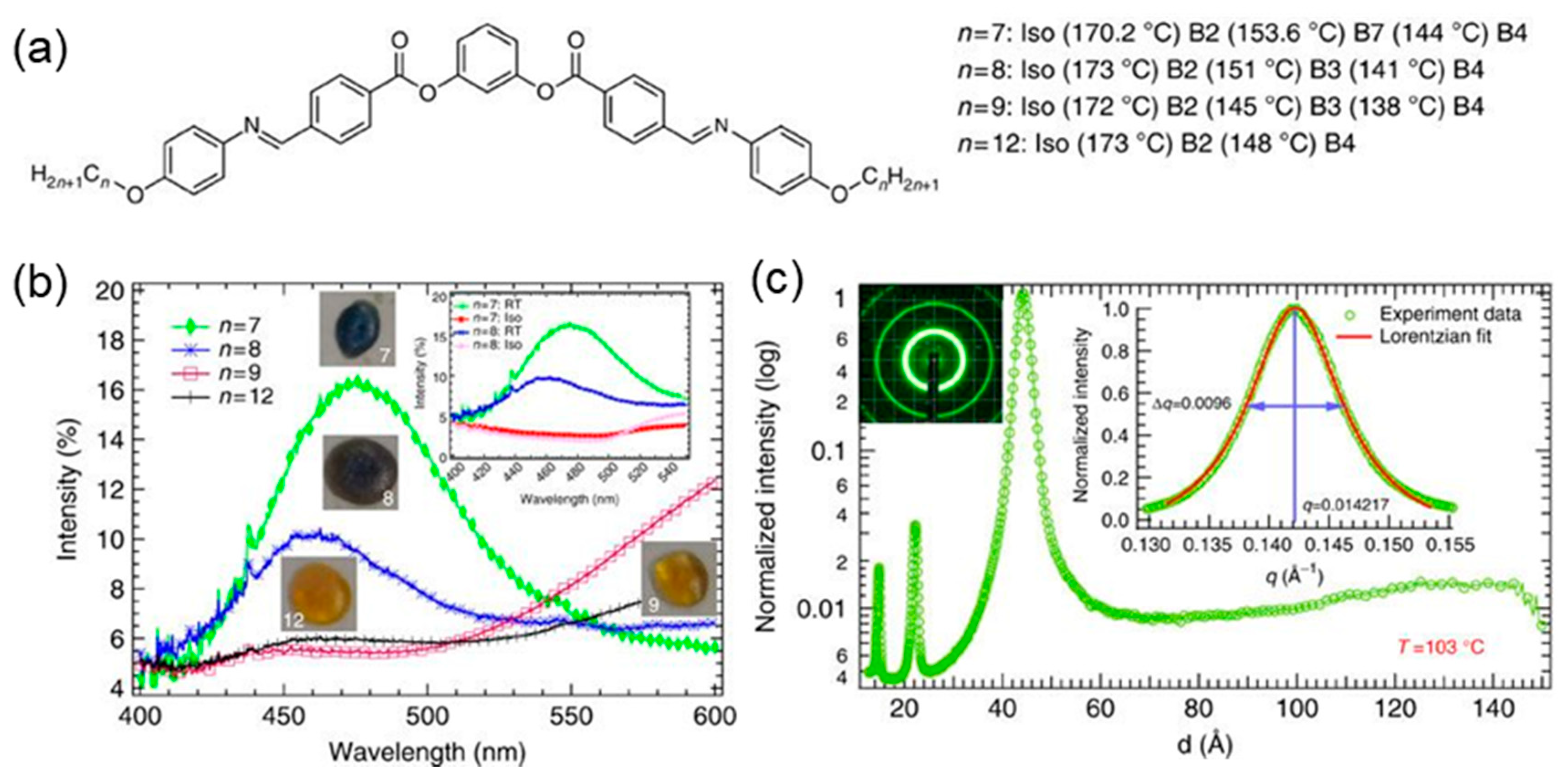
Following this pioneering work for the structural analysis, possible photonic or optical application using the HNF phase was suggested by Zhang et al. [49] in 2014 (Figure 2). The homologues named P-n-OPIMBs were used to form the HNF phase (Figure 2a), and their droplets on the flat substrate show interesting colors depending on the length of the end-group of the homologues (Figure 2b). In general, the HNFs are randomly oriented and coiled without any special surface treatment, showing the polycrystalline-like ring patterns through two-dimensional X-ray diffraction (2D-XRD) experiments (Figure 2c). This means that the HNFs are not well oriented in a large area, but the reflection color of the droplet of P-7-OPIMB and P-9-OPIMB is blue. This reflection color is a fascinating phenomenon considering the P-n-OPIMB series have a Schiff base that has a chemical absorption band near the 400 nm region that can reveal a yellow color, as shown in typical supramolecular LC compounds. Zhang et al. tried to explain this reflection color with the secondary twist structures when the HNFs are planar stacked to form piled HNF sheets on the substrate. More specifically, the second layer of HNFs on the first layer made of the HNF arrays do not stack parallel to each other in terms of the long axis of HNFs but rotate about 30°. Due to this, a secondary chiral structure with a periodic length of several hundred nanometers is formed, like twisted plywood architecture. This secondary structure can reflect a blue color by obeying Bragg’s law as a photonic crystal, which is also known as photonic crystal (PC). However, the structure could not be precisely controlled due to the absence of the aligning tools for the complex HNF phase, and the fine analysis for the color changes could not be carried out. Therefore, it was not easy to conduct the various kinds of optical experiments by varying the periodicity as the CLC did [50,51,52,53,54,55,56,57,58,59].

3. Orientation Control of HNFs

3.1. Conventional Alignment Methods to Orient HNFs

As mentioned in Section 2, the orientation control of HNFs was demanded for controlling the structural colors. Thus, relevant studies were conducted to control the orientation of HNFs using conventional surface treatment methods such as the rubbed nematic LC cell [60], self-assembled monolayer (SAM) [61], and microchannel [62]. For example, Araoka et al. [60] succeeded in guiding the horizontal orientation of the nematic–HNF mixture using the rubbing method because it is well known that the nematic phase is well-aligned uniaxially using the rubbed polyimide polymer film as used in LC displays (Figure 3a). For this, bent-core molecules (HNF phase) were mixed with rod-shaped LC molecules that can form the nematic phase, and this mixture was injected into a sandwich cell that has a rubbed polyimide layer at the isotropic temperature and then was cooled down to induce a thermal phase transition. The phase sequence and temperatures are Iso, 174 °C; B, 152 °C; B3, 140 °C; B4 and Iso, 240 °C; N, 51 °C; Cr. During the cooling process, the nematic LC phase was first formed and oriented parallel to the rubbing. The HNF-forming temperature is lower than the nematic phase, and thus HNF was grown parallel with the oriented nematic phase after further cooling. Uniformly aligned chiral domains were obtained by a thermal gradient to control the nucleation direction during the thermal phase transition (Figure 3a). The one edge of the sample was heated, while the other side was exposed to the air. So, the primary nucleation occurred at the hot edge and propagated toward the other edge. In this way, chiral domains could be controlled and have a linear shape.
The other approach was introduced by varying SAMs (Figure 3b–e) [61]. It is well known that the surface anchoring energy of the substrate to the molecules can be modified using SAMs, which are widely used to control the orientation of rod-shaped LC molecules parallel or perpendicular to the flat substrate. For example, tri-decafluoro-1,1,2,2-tetrahydrooctyl-trichororosilane (F-OTS) can induce homeotropic alignment (Figure 3b), while 2-(methoxy(polyethylenoxy)-propyl)trimethoxysilane (PEG6/9) can derive planar anchoring (Figure 3c) of the bent-core LC molecules, which form the B2 phase, one of the smectic phases. During the thermal phase transition, molecules are aligned first on the substrates in the higher thermal phase, for example, in the nematic phase, and the smectic layers are aligned based on this orientation at the lower temperature. HNFs can be grown from the pre-aligned bent-core molecules on cooling from B2 to the HNF phase, showing planar grown HNFs on the substrate in F-OTS-treated cells (Figure 3d), while perpendicular alignment of HNFs was found in PEG 6/9-treated cells (Figure 3e). This work was important to make aligned HNFs in a large area, which enabled us to conduct the grazing incidence XRD (GIXD) experiments. Through this study, the intra- and intermolecular arrangements of bent-core molecules were demonstrated. However, the polycrystal-like diffraction peaks hinder further structural analysis due to the lack of long-range ordering. The contact area between the substrate and the molecules is too limited to create a well-controlled HNF phase considering the ratio of the interlayer area to the volume of the LC material. The surface area of the LC material must be increased using three-dimensional (3D) confinement, which will be discussed in the next section.

3.2. Cylindrical Nanoconfinement

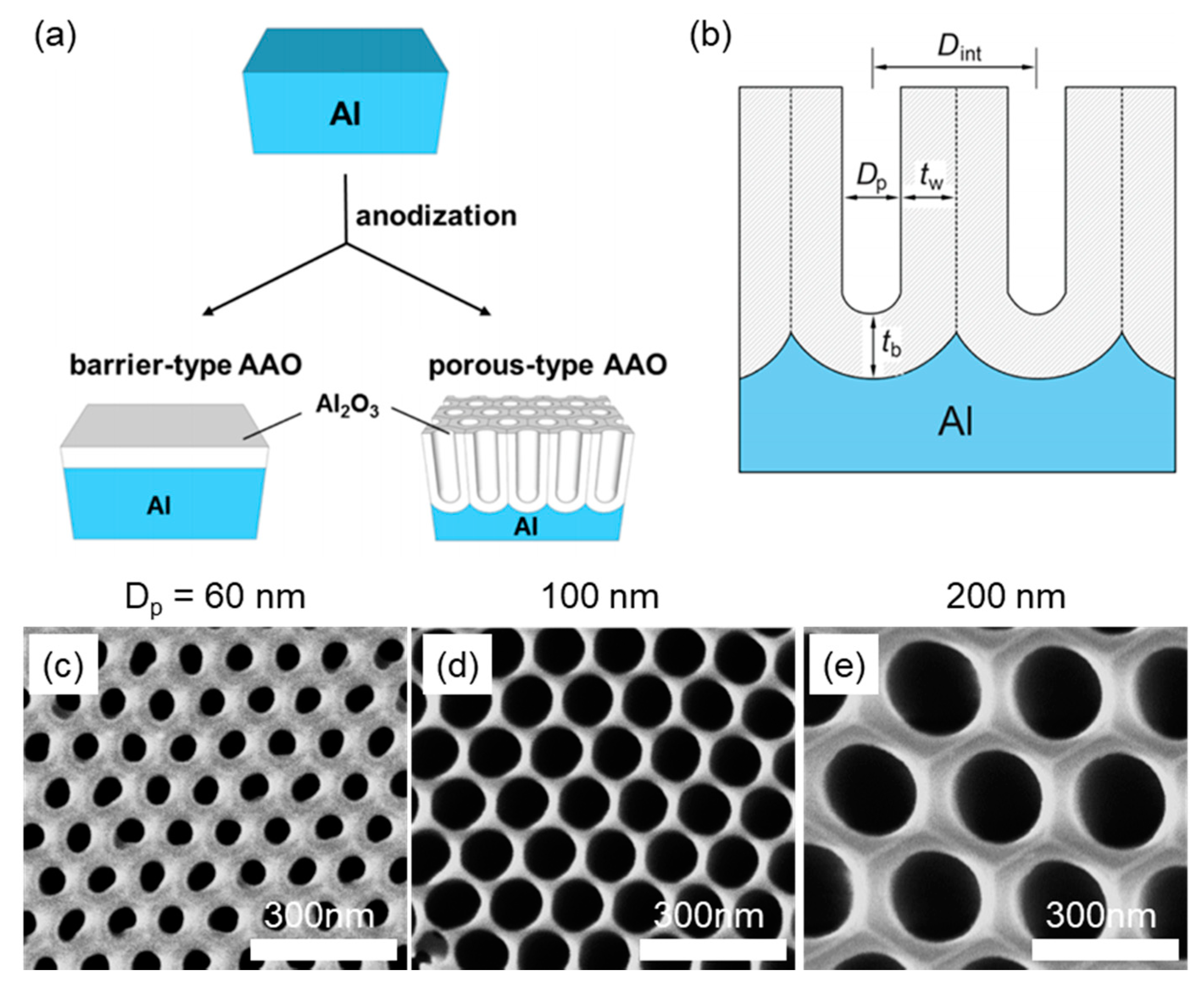
It is well known that aluminum forms an aluminum oxide layer on its surface through an oxidation reaction with oxygen in ambient conditions [63,64]. Electrochemically, an anodic aluminum oxide (AAO) layer can be artificially formed in the electrolyte solution by applying an electric field. Two types of AAOs can be formed, depending on the electrolytes used: barrier-type AAO and porous-type AAO (Figure 4a). Barrier-type AAO is fabricated using neutral electrolytes such as oxalate and has a smooth surface; it is widely used as a protective layer for aluminum. Porous-type AAO is manufactured based on acidic electrolytes like oxalic and sulfuric acid, having nanopores in the shape of a cylindrical structure. Compared to the common flat substrate, the AAO nanopores can provide much more surface area per unit volume, which can maximize the surface-anchoring effect to effectively control the orientation of HNFs. We will cover studies of orienting HNFs inside the porous-type AAO, which from now on are referred to as AAO. The confinement effect of the LC molecules in the nanopores of AAO is affected by two factors: physical size, related to the shape of the nanopores, and chemical treatment on the inner surface of AAO pores [65,66,67]. The uniaxial orientation of HNFs in the AAO-based confined geometry sounds reasonable considering the hollow cylindrical shape of nanopores. Indeed, the substrate’s inner surface can be variously controlled by using SAMs to induce homeotropic or planar anchoring conditions for the molecules. So, AAO can offer a physicochemical way to control the LC material’s orientation, inducing the aligned HNFs in the nanopores of AAO. Here, four parameters are controlled by varying the electric field and etching conditions, defining the structural features of AAO: pore diameter (Dp), interpore distance (Dint), barrier layer thickness (tb), and pore wall thickness (tw) (Figure 4b). Among these parameters, Dp is closely related to the substrate’s surface/volume ratio, so the main topic in this section is the morphological changes of HNFs caused by varying Dps (Figure 4c–e). For example, we can calculate the enhanced surface to volume ratio by comparing the flat and nanoporous alumina substrates with 1 cm2 top surface area and 5 μm depth. For an AAO film with Dp = 60 nm and Dint 100 nm, the surface/volume ratio of the substrate increases about 180 times compared to a flat substrate. In those studies, the parameters of an individual cylinder were the only things considered, though there were reports about controlling the type of packing structures of AAOs [63]. The growth of HNFs is restricted in each channel; there is no cross-talk. Therefore, only the hexagonal packing structure was considered, which is indeed the most common in AAO packing.

3.2.1. Nanoconfinement of HNFs

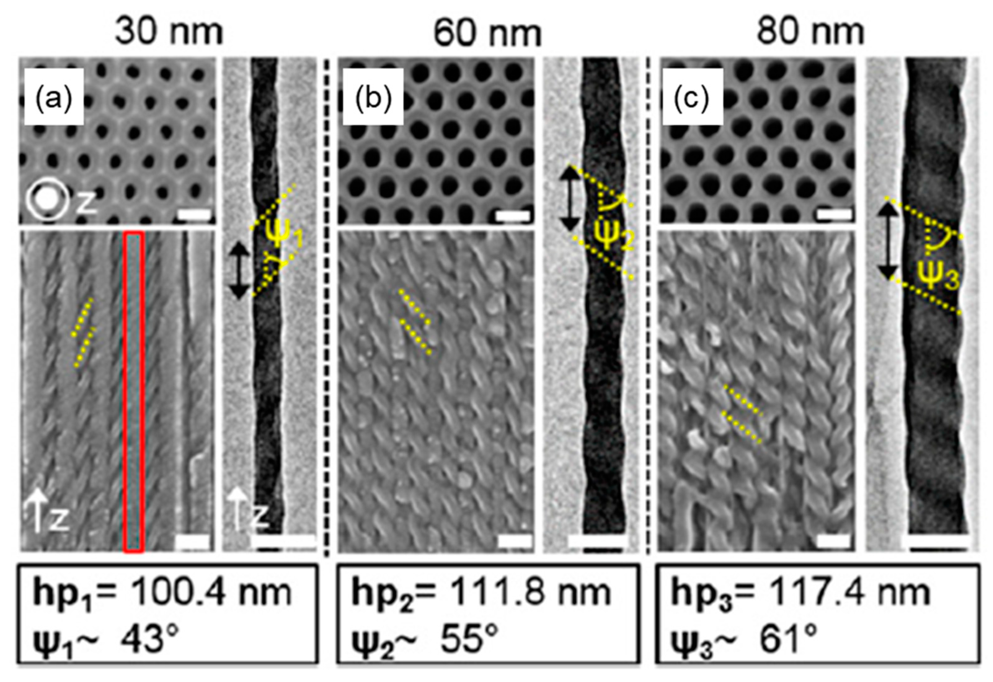
We have extensively studied nanoconfined HNFs in AAO with Dp changes since 2014 (Figure 5) [35]. The experimental procedure is simple but effective. First, bent-core LC molecules that can form HNFs, for example, 1,3-phenylene bis (4-(4-nonyloxyphenyliminomethyl) benzoate) (P-9-OPIMB or NOBOW), are placed on the entrance nanopores, which is on the top of AAO film, and the heating stage is placed under the AAO film. Second, the sample on AAO is heated to the isotropic temperature, and then the LC material in the fluid state is spontaneously injected into the pore in a capillary manner. Third, the temperature slowly decreases to form the HNF phase after the LC molecules sufficiently fill in the nanopores. Interestingly, an individually grown HNF at each pore along the cylinder’s axis is observed under 100 nm Dp. If Dp is over 100 nm, bundles of HNFs with a width of 30 nm are formed [35]. This phenomenon can be understood through the following description. The AAO channel wall has a high thermal conductivity to remove the heat generated during the phase transition on cooling to the HNF phase compared to the LC molecules. Also, the thermal gradient in the given condition is automatically generated from top to bottom due to the heating stage placed under the sample. Due to these factors, HNFs can be steadily grown through the nanopore. Moreover, this is a way of controlling the structural parameters of HNF, such as width (w) and helical pitch (p), by controlling Dp from 30 nm to 100 nm. Since HNF is formed to fill the inside of the nanopores, w is equal to Dp. For example, w varies from 30 nm to 80 nm when changing Dp from 30 nm to 80 nm. Indeed, half-pitch (hp) also varied from 100.4 nm to 117.4 nm, as shown in Figure 5.
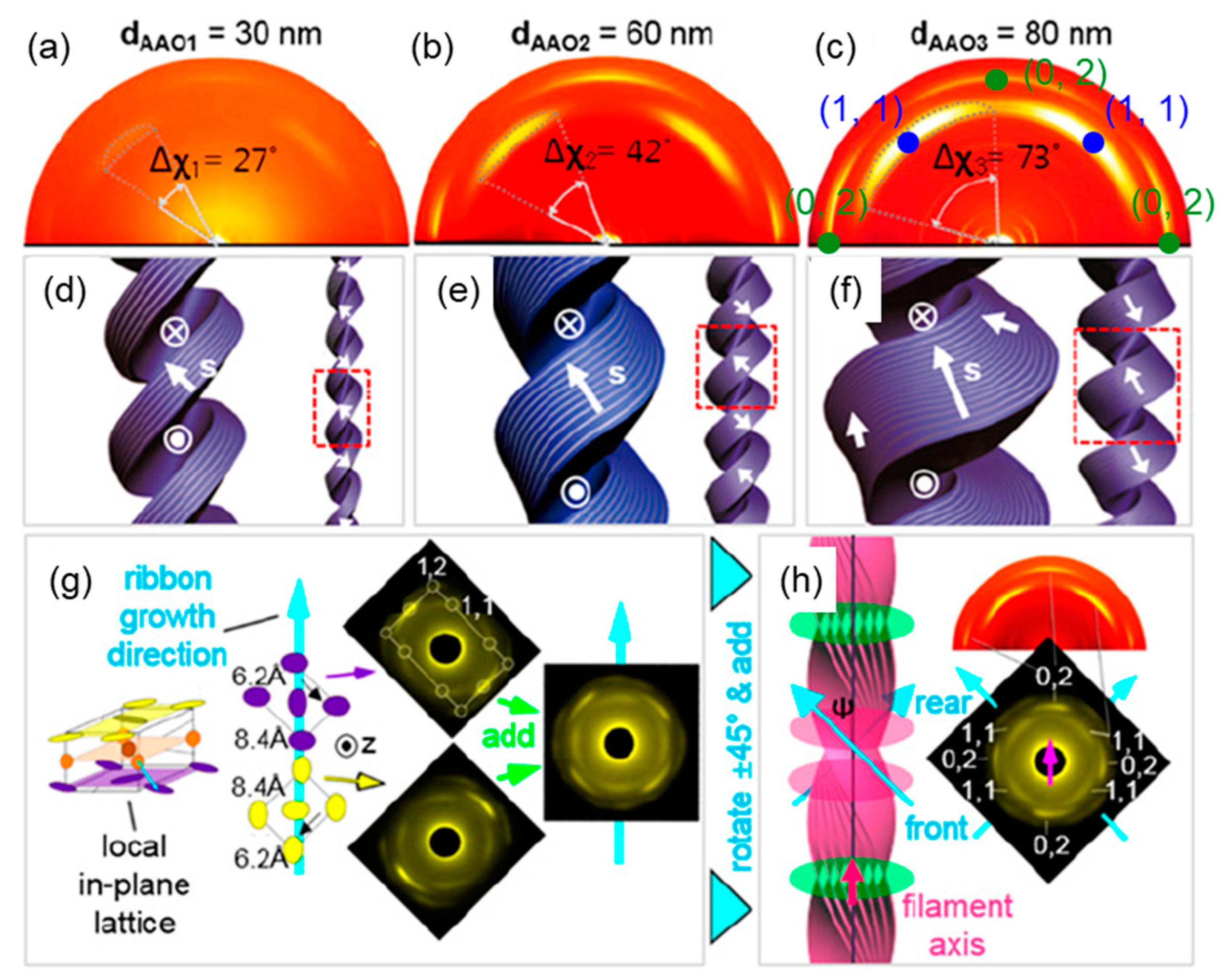
The HNFs aligned in the nanopores of AAO have identical shapes of helical structures regardless of the handedness, enabling us to do GIXD experiments to show the single crystal-like diffraction patterns (Figure 6). This is quite different from the bulk HNFs or HNFs on the SAM-treated flat substrate (Figure 3). In Figure 6a–c, the characteristic diagonal patterns are observed in the (0,2) and (1,1) planes. This is consistent with the results published by Hough et al. in 2009 [6], in which electron diffraction patterns were shown using a transmission electron microscope (TEM), which can be explained by the herringbone-like packing that bent-core molecules form inside the smectic layers. As described in Section 2, bent-core LC molecules consist of two arm planes (the yellow and purple circles in Figure 6g), tilted relative to the center aromatic ring (the orange circle in Figure 6g). Each arm plane forms a herringbone like a rectangular lattice when projected onto the center aromatic ring plane. Each arm plane has a rectangular reciprocal lattice, and the two lattices are combined and observed together through the GIXD (Figure 6h). The study reported that (1,1) and (0,2) reflections are formed by the aromatic group and aliphatic group of the molecular arm, respectively. This pioneering research to precisely control HNFs in nanopores of AAO triggered many other related control experiments: for example, molecular structures were varied to have bent-core, and dimeric LC molecules [38,68]; the size and shape of the AAO channels were modulated [37]; or the surface energy of the inner surface of AAO nanochannels [36] was controlled to enable systematic studies on HNF morphologies.

3.2.2. Chirality Control of HNFs with Cylindrical Nanoconfinement

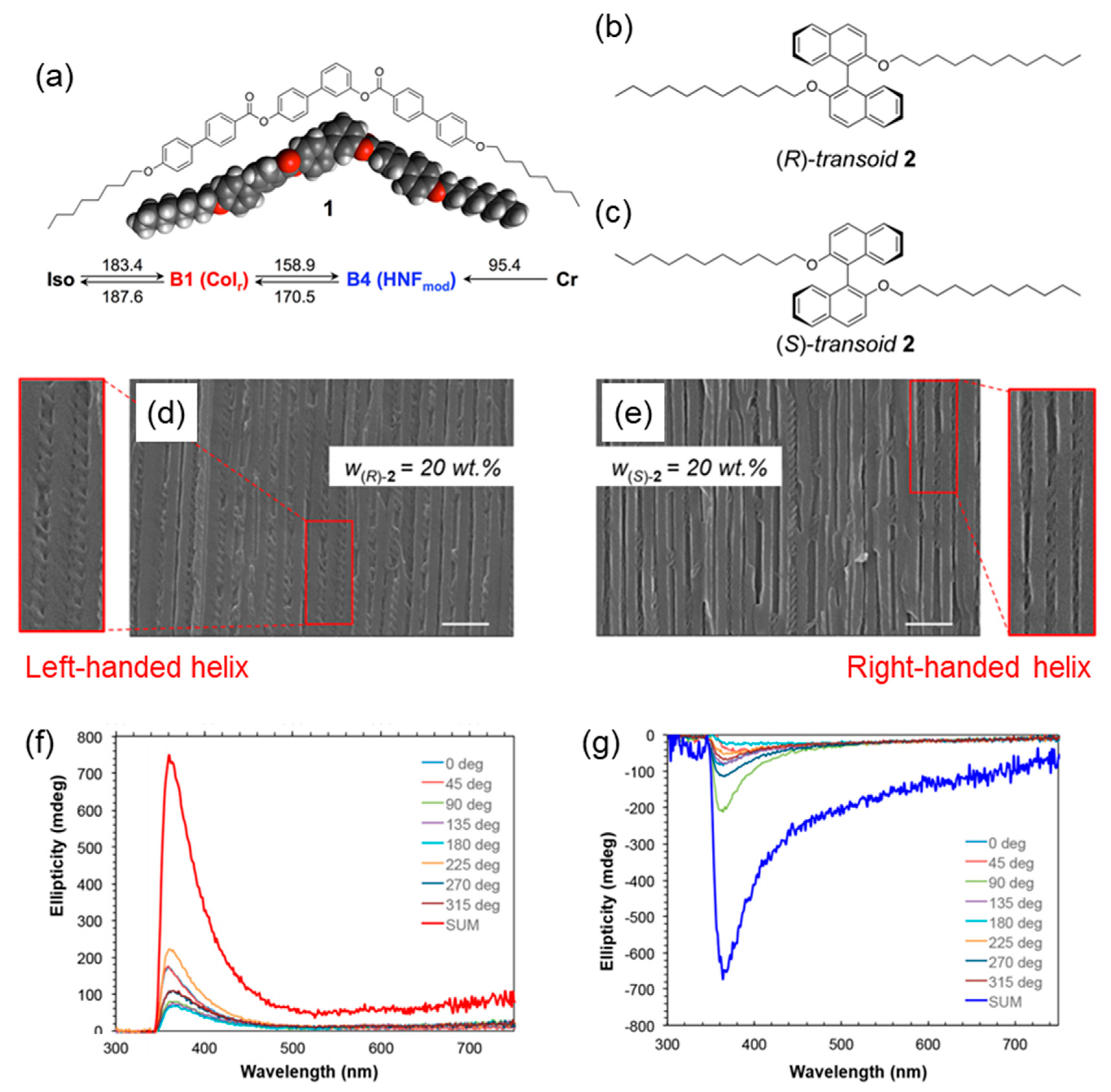
The HNFs intrinsically form a racemic structure composed of both left- and right-handed chiral domains because of the lack of chiral moiety, i.e., chiral center, though the HNFs have a helical shape resulting from a conformational or supramolecular chirality from achiral molecules. Therefore, the chirality can be varied depending on each nucleation point of HNF generation, but it undergoes chiral-preserving growth [69]. HNFs confined in the AAO nanochannel also show either left- or right-handed helical structures. To make the homochiral HNFs, Shadpour et al. recently reported on controlling the handedness of HNF in the AAO channel using chiral dopants [70]. For this, the chiral dopant was mixed with bent-core LC molecules at 20 wt % or less and then injected into the AAO film (Figure 7a–c). SEM and circular dichroism (CD) spectropolarimetry were used to prove that the mixture has homochirality within the AAO (Figure 7d,e). This was very interesting because the handedness of the same binary mixture was not controlled in a bulk state but controlled inside the AAO channel. In a bulk state, the bent-shaped molecules tend to assemble by themselves to expel the chiral dopant when bent-core LC molecules are nucleated to form HNFs. Therefore, the chirality of HNF is not controlled and remains in the racemic compound under this condition.
However, the bent-shaped molecules and the chiral dopant are well mixed, even at the nucleation site, and chirality is transferred to the bent-shaped molecules to form homochiral HNFs in the nanopores.

3.3. Photoalignment of Azobenzene

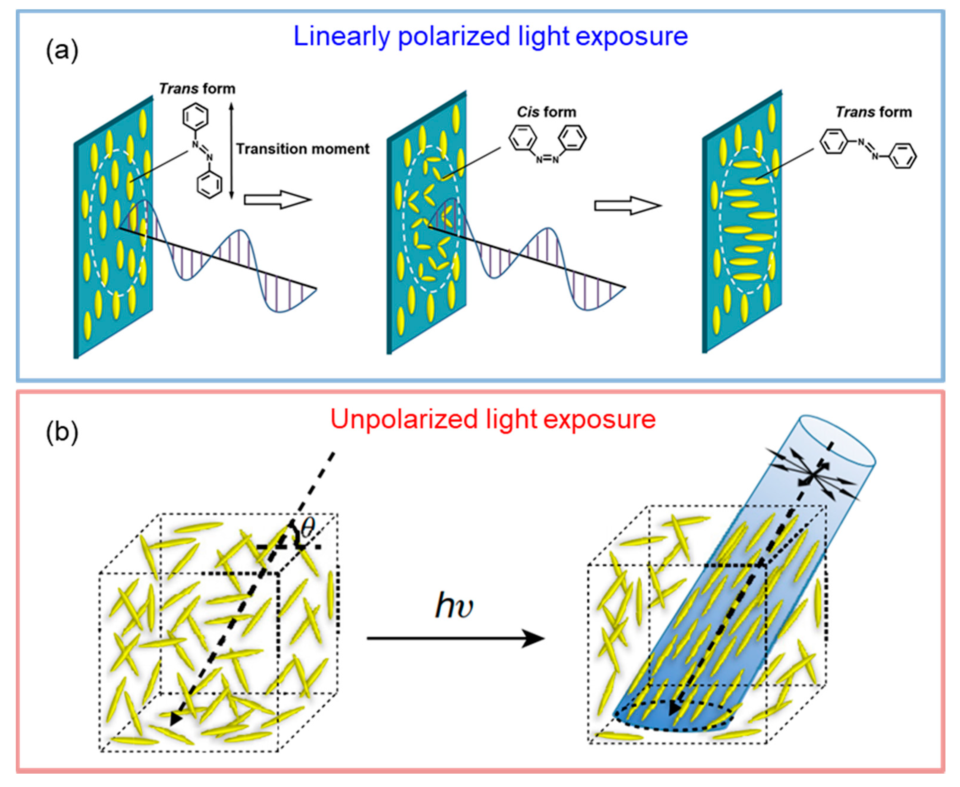
Photoalignment technology is actively used in various LC-based applications, such as LC display [71], smart windows [72], actuators [73], coating materials [74], etc. The most representative organic moiety of the photoalignment material is the azobenzene group. Azobenzene has a photoisomerization property that changes the conformation from trans to cis when ultraviolet (UV) light shines on the sample, while a cis to trans transformation happens when the visible light shines on the sample or when it is exposed to heat. It is known that azobenzene is more stable in the trans-state, considering the energy level. Therefore, azobenzene in the equilibrium state tends to be biased to the transisomer. Interestingly, reversible photoisomerization is repeated until transisomers stop absorbing light when the azobenzene-containing molecule is exposed to continuous UV light. This results from the angular selectivity of the azobenzene moiety, which is known as the Weigert effect [75,76]. For example, the light-absorbing efficiency is determined by the following equation when the azobenzene moiety is exposed to the linearly polarized UV light:
U(θ) = V0cos2θ
where U(θ), V0, and θ refer to the effective orientation potential, the strength of the potential, and the angle between the principal molecular axis and the polarization of light, respectively. This simple equation can explain the rotation of azobenzene moiety at θ = 90° to minimize U(θ) (Figure 8a). However, the molecules cannot minimize the U(θ) when they rotate within the in-plane direction when unpolarized UV light shines on the azobenzene moiety. In this case, U(θ) can be minimized by changing the orientation of azobenzene moiety in the direction of light propagation (Figure 8b). In other words, by irradiating azobenzene derivatives with unpolarized UV light, the orientation of molecules can be changed to be parallel to the light-propagating direction. In this section, the study of the photoalignment of azobenzene-containing bent-shaped LC molecules will be discussed.

3.3.1. Photoalignment of HNFs

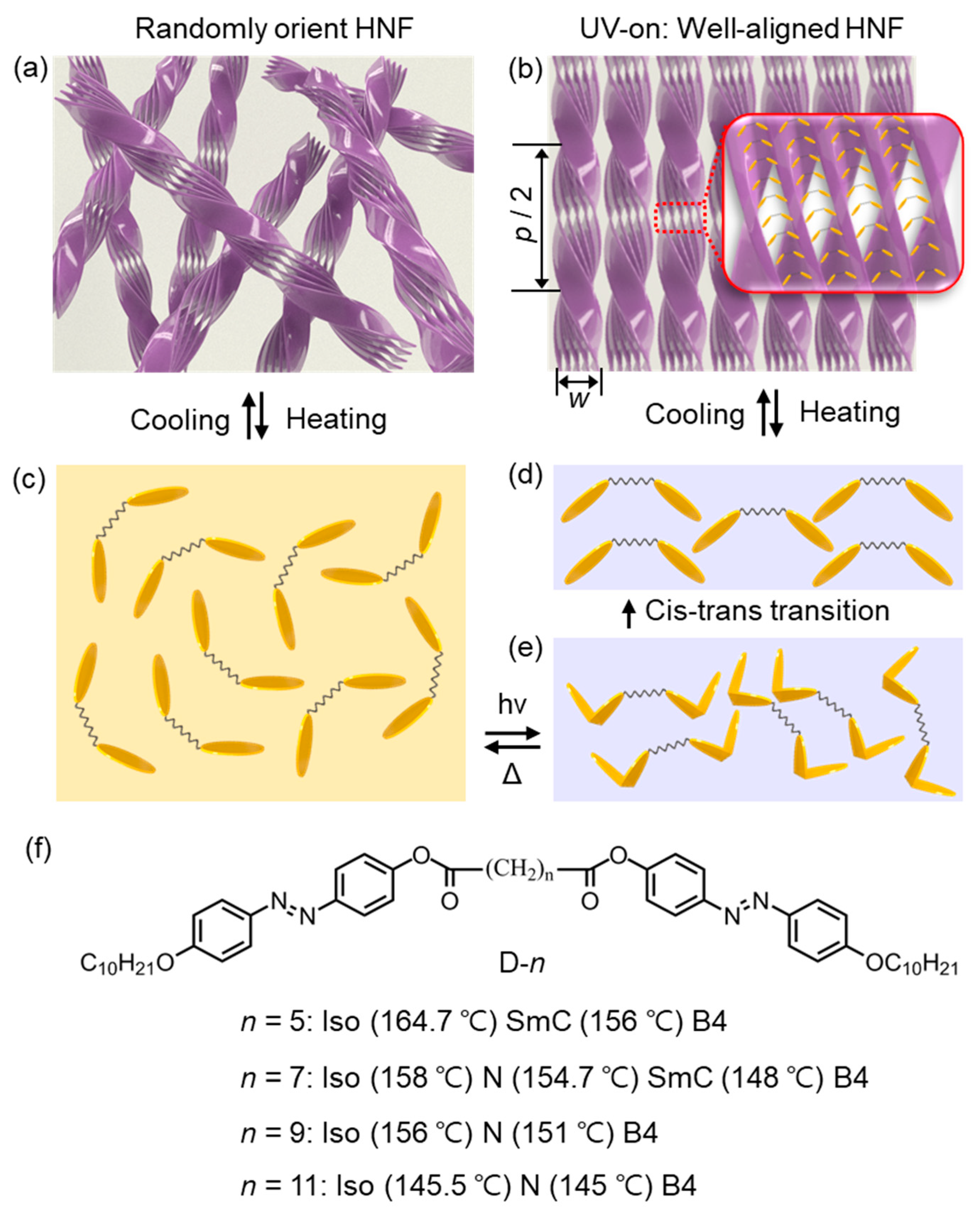
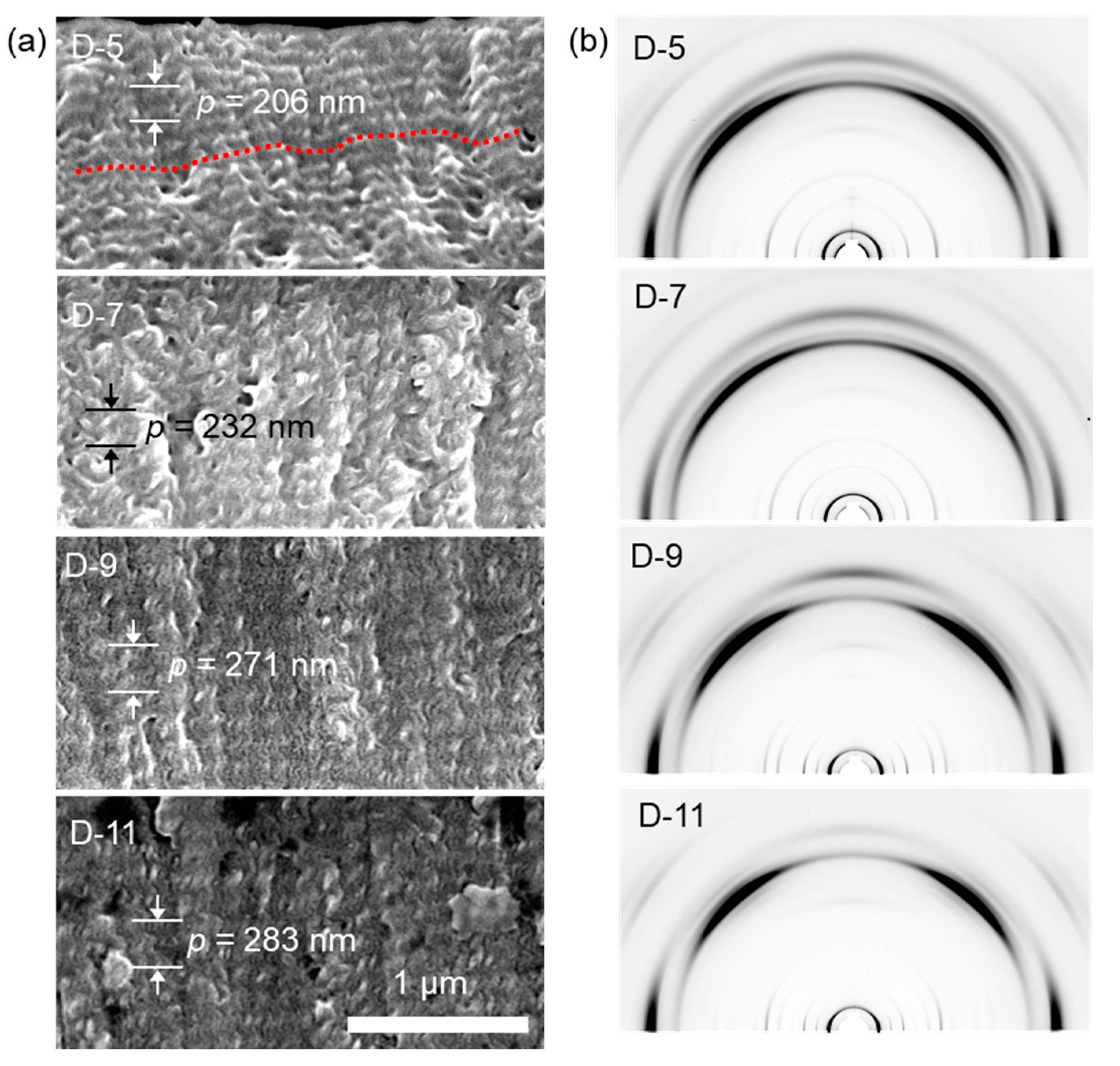
A dimeric LC molecule with two azobenzene moieties was first reported by Zep et al. (D-n in Figure 9f) [40]. The dimeric LC molecules used in this research are different from other dimeric molecules that form a twist bend nematic (NTB) phase. Unlike NTB-forming molecules, an HNF-forming molecule has ester groups in its linkage part, which allows the arm parts to be tilted. When the sample is exposed to UV light, D-n molecules also undergo reversible photoisomerization (Figure 9c,e) and eventually minimize U(θ) by reorienting the molecules by the Weigert effect. If D-n molecules are exposed to unpolarized UV light, the molecules change their orientation by reorienting their polar director parallel to the light-propagating direction (Figure 9d) [7]. Generally, randomly oriented HNFs are formed when dimeric molecules are cooled from the isotropic temperature without shining UV light (Figure 9a). However, uniformly oriented HNFs are formed in a bulk state when unpolarized UV light is shined on the sample during the thermal phase transition (Figure 9b). The uniformly oriented HNF structure was analyzed in detail using SEM and GIXD. The helical pitch increases significantly from 206 nm to 283 nm, as the alkyl length in its linkage part increases from 5 to 11 (Figure 10a). Moreover, a single crystal-like diffraction pattern was observed in GIXD patterns since the structure was well-controlled in a large area with a high degree of alignment, which is almost identical to the GIXD pattern of HNFs confined in AAO, as shown in Section 3.1. It is of note that this photoalignment technology of HNF has many advantages over the conventional alignment technologies because it does not require an additional template, alignment layer, and various other additives. Most importantly, this photoalignment technique could be applied to various optical films, including patternable photonic crystal and chiral sensors, which will be covered in detail later.

4. Optical Applications of HNFs

4.1. Template for Chiral Assembly of the Guest Material

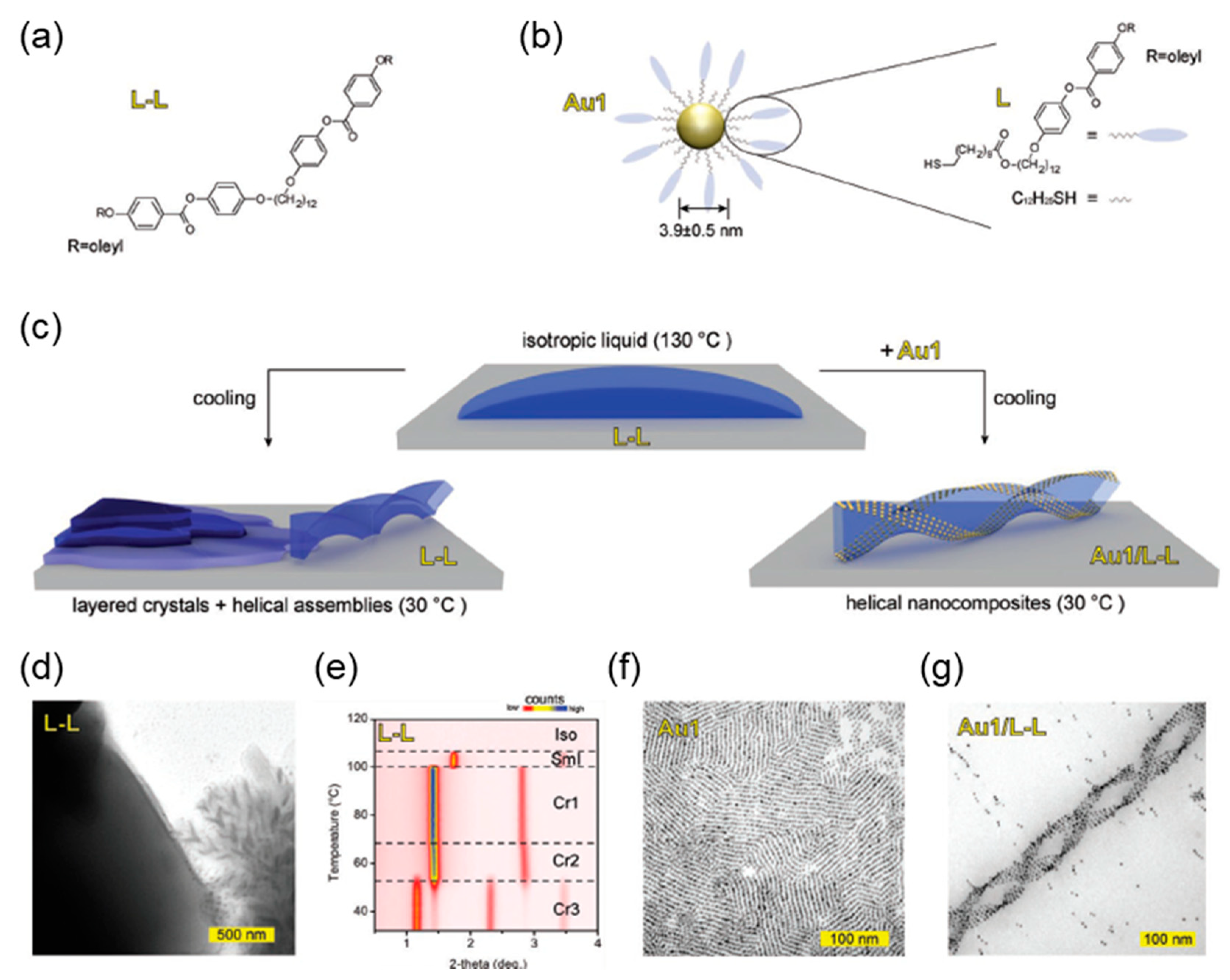
HNF has the potential to be used as a template to induce chirality in achiral organic/inorganic materials because of its chiral shape and firmness [77,78,79,80,81,82,83]. If the chirality transfer succeeds in metal nanoparticles [84], fluorescence dye, and additional LC molecules, various chiroptical applications can be rationalized, for example, tailored polarization rotation [82], photonic metamaterial [85], chiral fluorescence [86], etc. Recently, various chiral templating applications have been studied. For example, Bagiński et al. reported [45] helical assemblies of plasmonic nanoparticles, in which the mesogenic ligand groups were introduced on the surface of gold nanoparticles (GNP), then mixed with dimeric LC molecules that can form the HNF phase (Figure 11). Here, the mesogenic ligand, L, has a similar chemical structure to the dimeric LC molecule (L-L), thereby successfully placing the GNP along the helical surface of HNF (Figure 11a). It is well known that the arrangement [87,88], orientation [89], and distribution of metal nanoparticles like GNP are important in order to utilize surface plasmonic resonance (SPR) induced from the surface of metal nanoparticles. For this, Bagiński et al. synthesized the HNF-forming dimeric LC molecule, L-L (Figure 11a,b). Originally, the L-L molecule forms mixed structures of layered crystal and HNF when cooled from the isotropic temperature (Figure 11c–f). However, GNP forms a helical superstructure along with the shape of HNF, when the binary mixture, L-L and Au-1, is cooled from the isotropic temperature (Figure 11c,g). The structure was investigated using TEM, atomic force microscopy (AFM), and XRD. Such a gold helix can be applied to chiroptical applications such as chiral plasmonic and metamaterials [82,85].
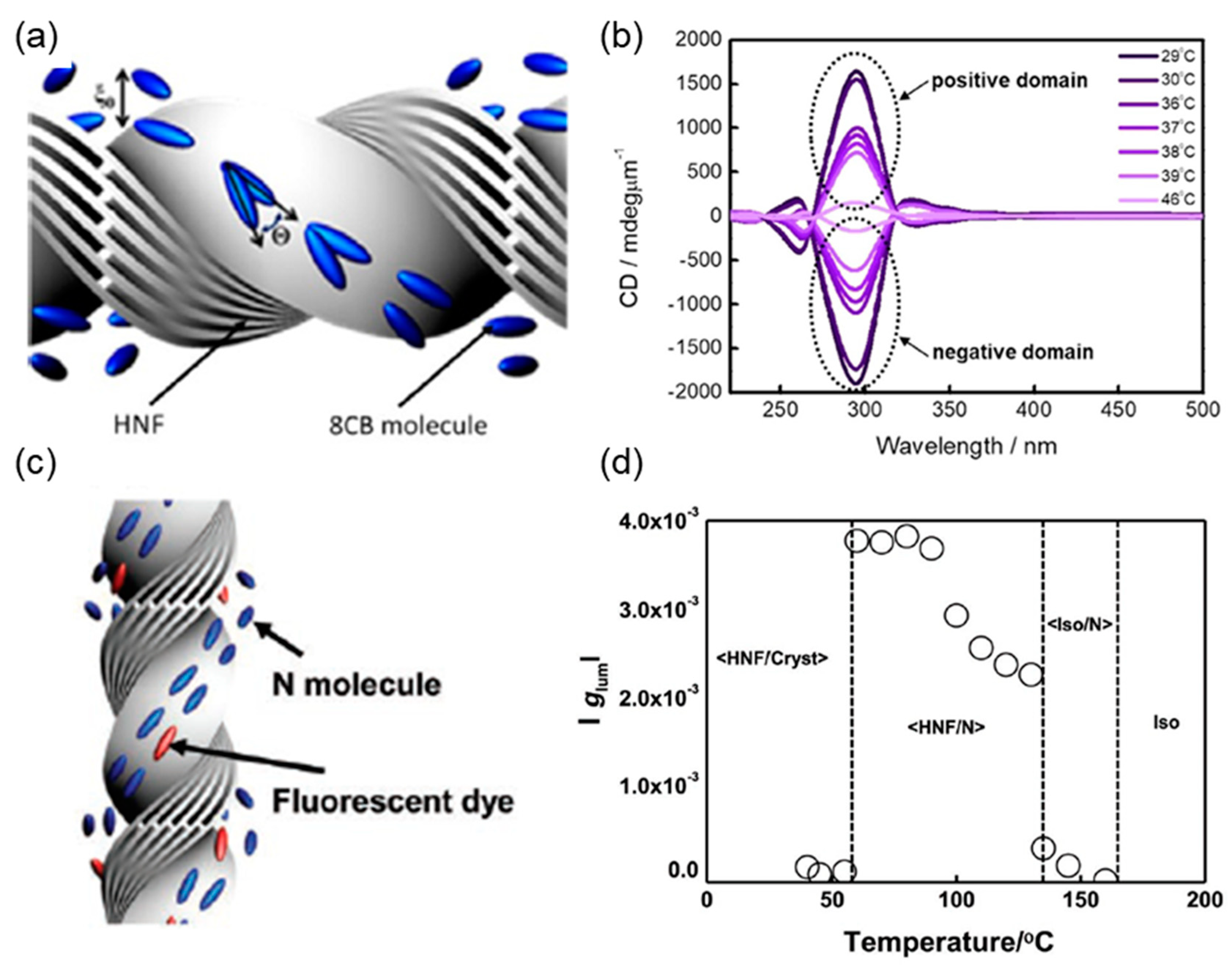
According to a report by Jeon et al. [46], when a bent-core LC molecule is mixed with a rod-shaped LC molecule 4′-octyl-4-biphenylcarbonitrile (8CB), the HNF phase is formed first, followed by 8CB phase transition of the nematic and smectic phases. At this moment, 8CB molecules rotate along the surface of HNF, and chirality is transferred to 8CB molecules (Figure 12a). The process of chirality transfer was analyzed via an in situ CD experiment by varying the temperature. At temperatures below 100 °C, where the phase of the bent-core molecule is set in the HNF phase, and the phase of 8CB changes, the CD signal of the binary mixture changes significantly. In Figure 12b, at 40 °C, where 8CB is in the isotropic phase, the CD signal is low because the intensity is solely from the HNF. However, as the temperature decreases and 8CB goes through a phase transition, the CD signal is amplified. For example, 8CB is in the nematic and smectic phase at 37 °C and 25 °C, respectively, and the CD signal is amplified sequentially (Figure 12b). From this, it can be seen that the chirality of HNF is successfully transferred to the surrounding LC molecules that form the nematic and smectic phases. Additionally, a rod-shaped fluorescence dye molecule that mixes well with nematic LC molecules is added [47]. Because of the favored chemical affinity between those components, this dye molecule could be co-aligned with the nematic LC on the HNF surface, so the chirality of HNF was also transferred to the dye molecule (Figure 12c). Therefore, fluorescence is emitted in the form of circularly polarized light (CPL). Figure 12d summarizes the luminescence dissymmetry factor (glum) according to the phase of the surrounding LC medium. glum is determined by the following equation, where Ileft and Iright are the intensity of left- and right-CPL, respectively:
glum = 2(Ileft − Iright)/(Ileft + Iright)
The larger the absolute value of glum, the closer it is to circular polarization. In Figure 12d, the |glum| value increases only in the HNF/nematic phase, where chirality is transferred to the surrounding medium from the HNFs. Finally, the circularly polarized luminescence was generated from the achiral fluorescence dye.
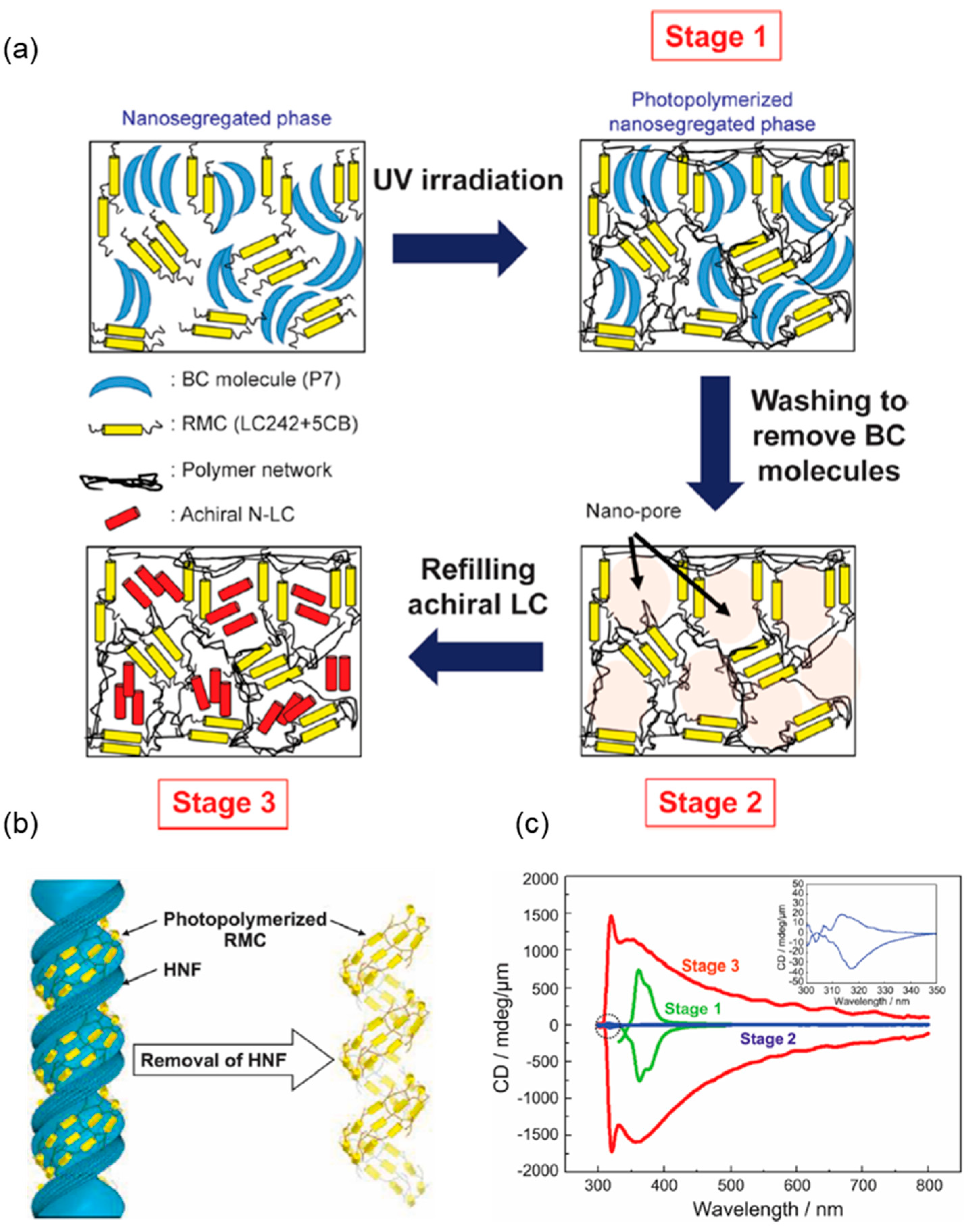
The chirality of HNF can be transferred not only to small molecules but also to polymeric networks [90]. This chiral polymer can be used as a template that can induce chirality in additional small molecules. When a bent-core molecule and a photoreactive mesogenic compound (RMC) are mixed to form the HNF phase, the chirality of HNF is transferred to RMC (Figure 13a). After this, RMC was photocrosslinked using UV light, and a chiral polymeric network formed around the HNFs’ surface (Stage 1 in Figure 13a). Then, HNF was selectively removed, leaving only a pure polymeric network with a nanosized chiral void using an organic solvent like 1,2-dichlorobenzene (Stage 2 in Figure 13a,b). This chiral void can be used as an additional template to induce chirality in small molecules. For example, more achiral nematic LC molecules were injected into this template, and chirality was induced in this nematic LC (Stage 3 in Figure 13a). The transfer and amplification of chirality were verified by measuring CD for each stage (Figure 13c). In Stage 1, a CD signal from HNF and the surrounding polymer was observed. On the other hand, CD was significantly reduced in Stage 2, and only a weak CD was observed around 300 nm, which corresponds to the polymer’s absorption wavelength region. In Stage 3, the CD was amplified in a broad wavelength range, and it was proven that the chirality was not only transferred but also amplified, with the confined nematic LC medium inside the chiral polymer.
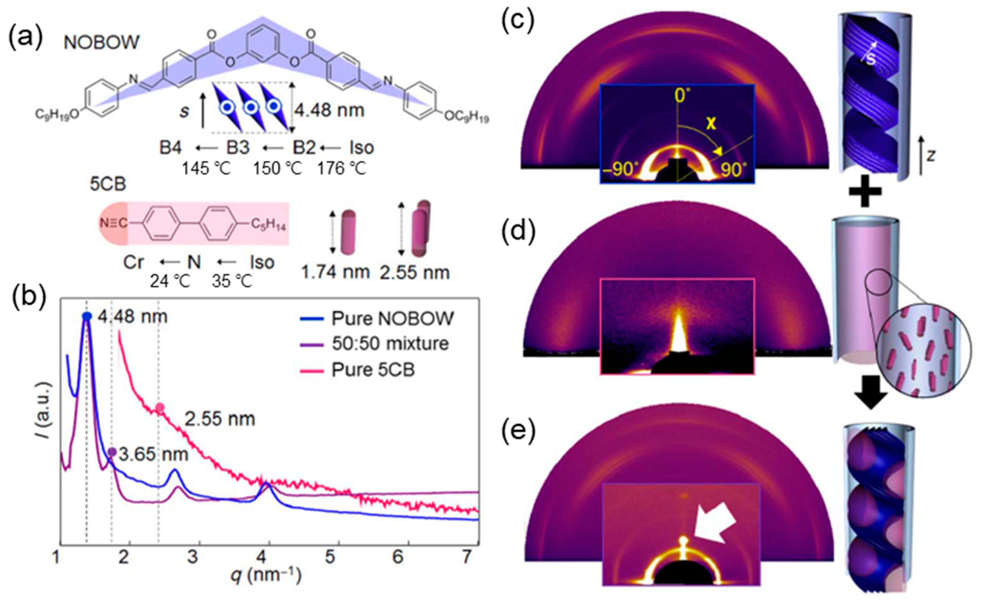
The HNFs have a helical topographical shape in the nanopores of AAO film, meaning that corresponding helical voids spontaneously formed between HNF and the AAO channel wall. These voids might be used as a template to guide the other guest material because the HNF has solid-like firmness in ambient conditions [39]. Based on this simple idea, a host (HNFs in the nanopores) and guest (typical rod-shaped LC molecule) system could be realized. A bent-core molecule, NOBOW, and rod-shaped molecule, 4′-n-pentyl-4-cyanobiphenyl (5CB), were melted and mixed together with 50:50 wt % ratio (Figure 14a). After injecting this mixture into the AAO channel with a Dp of 60 nm, as in the previous work, the structure was analyzed by scanning electron microscopy (SEM) and GIXD (Figure 14b–e). The GIXD patterns were compared with neat NOBOW, neat 5CB, and a mixture of these. As described in Section 3.2.1, NOBOW molecules have a rectangular wide-angle peak with vertically oriented HNFs. In addition, the small-angle pattern is observed in the χ~90° region because the direction of the layer has a slightly tilted long axis of the AAO channel (Figure 14c). In contrast, the nematic phase formed by neat 5CB shows broad GIXD peaks because of the relatively low ordering (Figure 14d). One can expect 5CB molecules to be subjected to confinement between HNF and AAO nanochannels due to chiral voids. As a result, a binary mixture of 5CB/NOBOW has an exceptionally high degree of orientational and positional order and forms a dot-like diffraction pattern in the region of d = 3.65 nm (d is defined as the lattice parameter of the sample measured from the XRD experiment. This can be calculated by the relationship of d = 2π/q, where q is directly extracted from Figure 14b), which is larger than the contour length of two 5CB molecules, as explained by the complex of NOBOW and 5CB (Figure 14b,e).

4.2. Photonic Crystal Made of Aligned HNFs

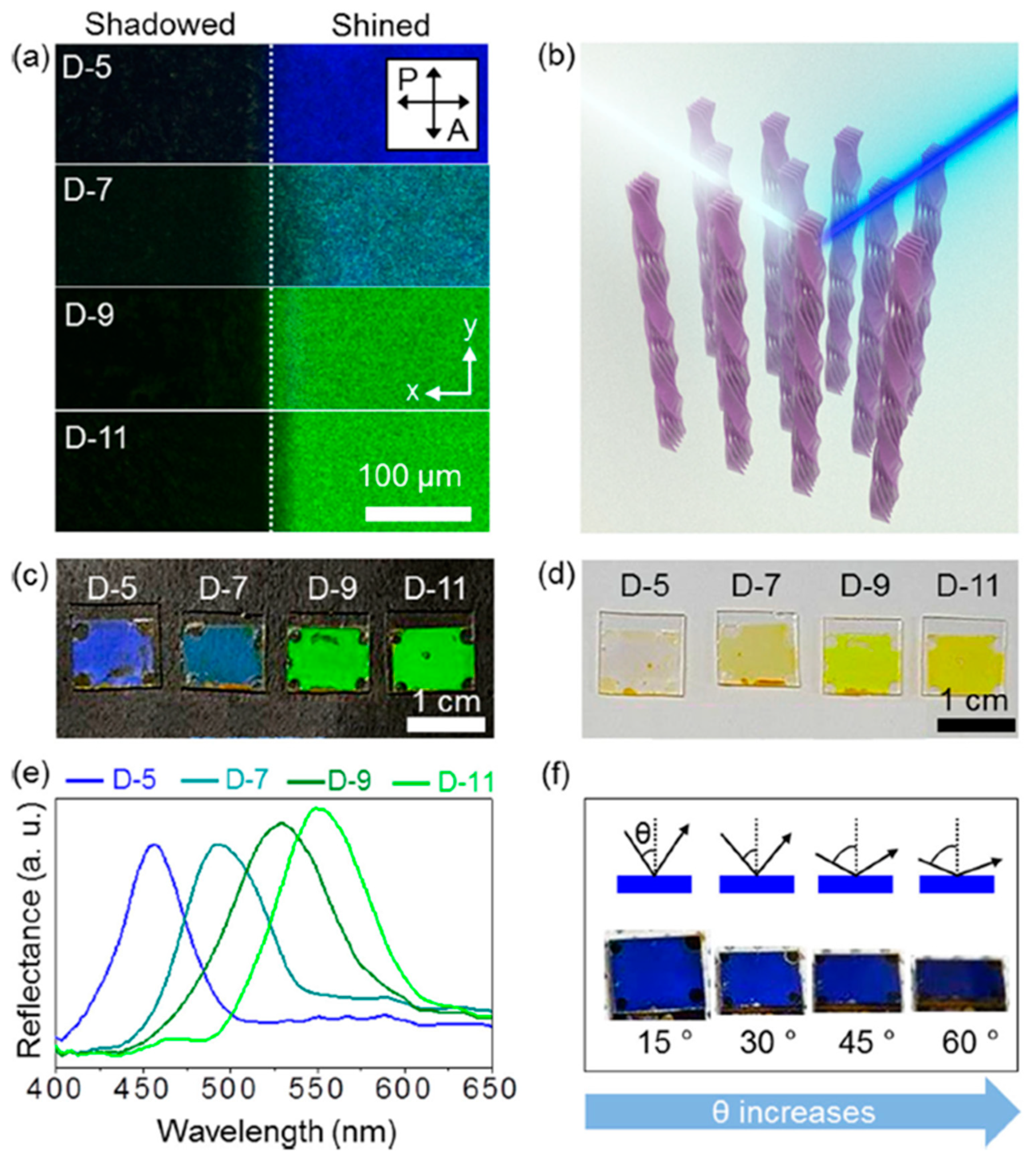
Section 3.3.1 introduced the photoalignment of HNF using D-n molecules (Figure 9f). Unlike other techniques for controlling HNF, photoalignment allows the uniform orientation of HNF in a large area without the aid of a template. Interestingly, very clear structural colors were observed in the photoaligned HNFs (Figure 15) [7]. According to Zhang et al. [49], it has been reported that the blue structural color is generated from the secondary twist structure of HNF (Figure 2). However, HNF at this time was randomly oriented within the in-plane direction, which is clearly different from a vertically and uniformly oriented structure. We succeeded in orienting the HNF in the bulk state and observing the structural color; this was for the first time we have realized HNF-based photonic crystal patterning. Unlike the secondary twist HNF model, vertically oriented HNF caused an electromagnetic coupling effect, resulting from densely packed nanostructures [91,92]. Due to this phenomenon, the effective refractive index of vertically oriented HNF was enhanced, forming the visible wavelength structural color, and it changed from blue to green by controlling the alkyl linkage length of the D-n molecule (Figure 15a–c,e). There is more than one refractive index in bent-shaped molecules because of their unique shape. The effective refractive index from the HNF film should consider the molecular director, polar director, and tilting director, which is not so simple because the value can vary depending on the molecular orientation [93]. The structural color generated from HNF was investigated by comparing the color of the HNF-film on a black and white background. The black background absorbs all of the light transmitted through the HNF film and induces a vivid reflection color (Figure 15c). On the other hand, the white background scatters the light transmitted through the sample, thereby inducing both the reflected color and the transmitted color visible [7,94]. Based on this, the photonic crystal property of the vertically oriented HNFs was verified as the reflected and transmitted colors were different. The photonic crystal made of vertically oriented HNF has various advantages over conventional CLC and BP because HNF is mechanically and thermally stable because it is a solid-like LC phase. For example, the structure of HNF and the resultant reflection color are maintained over a wide temperature range, from room temperature to 150 °C, without any additional polymerization process, which is a remarkable achievement because the CLC and BP phases usually have a limited temperature range that is much narrower than that of HNF. So those CLC and BP phases always require additional stabilization processes such as photopolymerization. Furthermore, the alignment layer and template are not necessary for the orientation of HNF, which are essential techniques for CLC and BP phases, and various patterns can be produced on demand using a patterned irradiation method [95]. Generally, photonic crystals have angle-dependent color changes, defined as iridescence coloration due to the directionality of the lattice plane [33,96]. In Bragg’s equation below, θ represents the incident angle of the light and is related to the viewing angle. So, the wavelength of reflected light can be changed.
λ = 2ndcosθ
Interestingly, HNF has an amorphous photonic crystal property. In Figure 10, the pseudo-1D layer formed by oriented HNF (red dashed line in Figure 10a) has a certain degree of undulation, so the crystal orientation is weakened, and the angle-dependent color change is suppressed (Figure 15f) [96,97,98]. For these reasons, HNF is expected to be superior to the conventional fluid CLC phases, which can be used in more advanced chiroptical applications such as patternable photonic crystals with enhanced stability and reduced angle-dependency. Also, the unique chiral sensing application can be possible using the racemic property of HNF, which will be discussed in Figure 16.
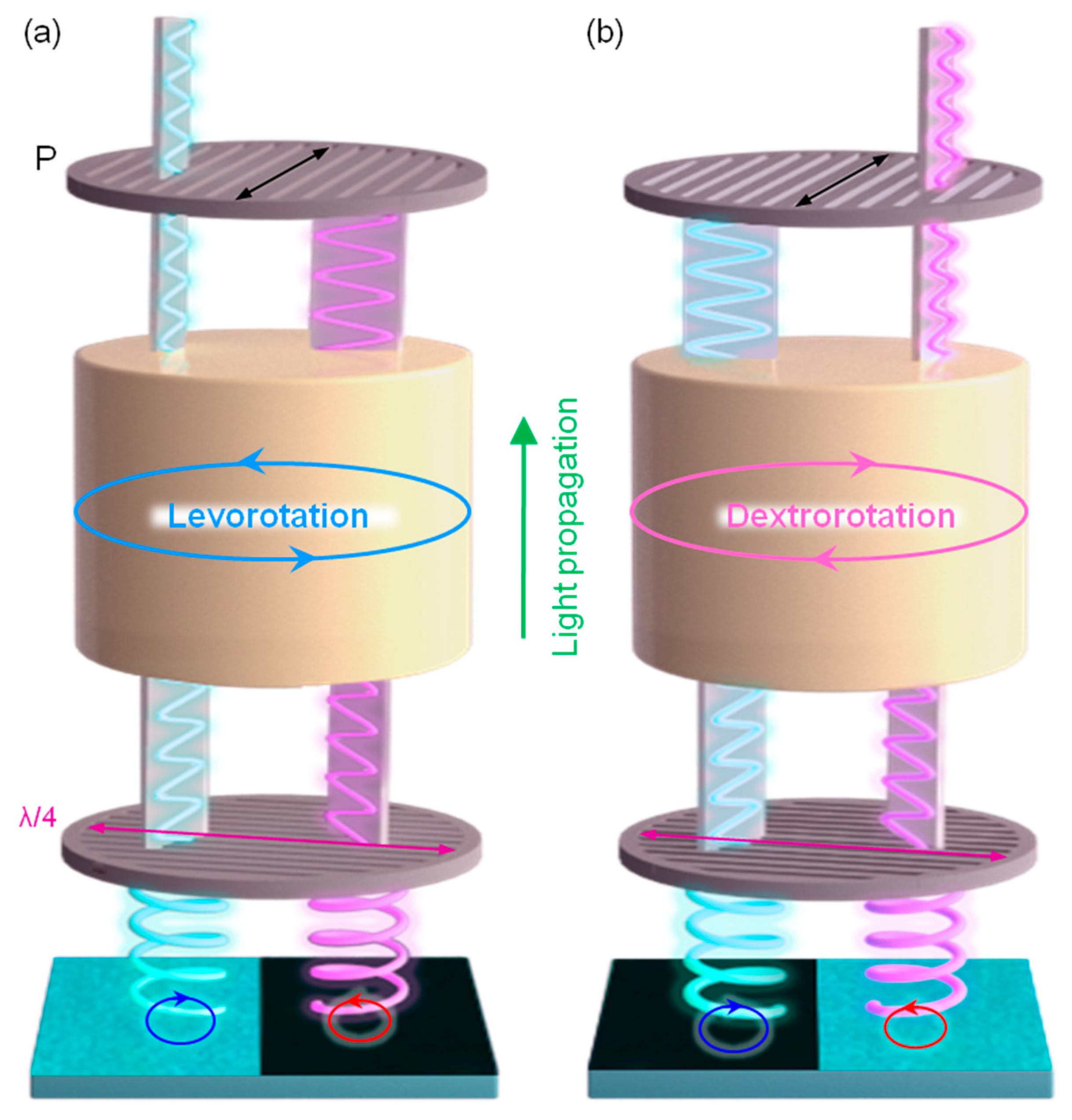
In a subsequent study, we suggested a chiral sensing application with helical nanofilament-based photonic crystal (HNF-PC) (Figure 16) [20]. Similar to CLC and BP, HNF-PC also reflects CPL due to the chiral nanostructure [99,100,101,102,103,104,105,106]. As mentioned in Section 3.2, HNF is a racemic mixture, so r- and l-CPL are reflected in the right- and left-handed chiral domain, respectively. Interestingly, since the chiral domain of HNF is on a several mm scale, it is easily detected by the naked eye without any optical magnifier. We converted the reflected CPL from HNF-PC into linearly polarized light (LPL) using a quarter-wave plate (the slow axis is marked by a pink arrow in Figure 16a,b), and then applied it to the detection of chiral substances such as fructose and glucose. Specifically, fructose dissolved in water has an optical rotation property that rotates LPL. If the given solution has (−) chirality, LPL is rotated counterclockwise, and for a (+) chiral solution, LPL is rotated clockwise. Simply speaking, the LPL rotates differently according to the chirality of the solution, and this rotation is detected through a polarizer (Figure 16). Finally, the chirality of the solution is detected depending on which domain appears brighter.

5. Conclusions

In this review, we have introduced and discussed the orientation control of the HNF phase and its various chiral applications. In the first part, two major methods of orienting HNF have been discussed. First is geometrical nanoconfinement using a porous AAO film, which can maximize the confinement effect due to the enhanced surface/volume ratio. The nanoscaled 1D channel wall not only induces the individually and uniaxially grown HNF, but also the modified surface chemical-anchoring conditions by using SAM treatments. Second is photoalignment with azobenzene containing bent-shaped LC molecules. Unlike the previous method using a template, it offers bulk state uniaxial alignment in a large area and gives a chance to create cross-talk between adjacent HNFs, such as an electromagnetic coupling effect to enhance the effective refractive index. Using those two methods, uniformly oriented HNF with a single crystal-like XRD pattern can be obtained. The molecular configuration—a herringbone-like crystal lattice and smectic layered structure—has been investigated in detail based on this XRD result. In the second part, various chiral applications have been shown including templating, plasmonic, fluorescence, photonic crystals, and sensors. Because of the firm structure, which is very similar to the solid phase and chiral nature of the HNF phase, it could transfer its chirality to various types of materials such as plasmonic particles, fluorescence dye, and a polymeric network. Various chiral phenomena such as CPL luminescence and CD could be realized with only achiral compounds based on this templating system. Also, vertically aligned HNF itself shows a photonic crystal property due to the periodic structures of several hundred nanometers in size. In particular, light propagation and polarization were controlled because of the chiral photonic crystal nature.
The HNF phase has many potential applications to be studied beyond the existing chiral LC materials such as CLC and BP because of its unique polar and chiral characteristics made from achiral molecules and solid properties. One of the most powerful characteristics of HNF is its crystal-like stability. Unlike conventional LC phases, it is more like a solid phase and is very stable thermally and mechanically without any polymerization. This is a very important property because its structure can be investigated more precisely with AFM, SEM, TEM, and GIXD, which are not suited to CLC and BP analysis because of their fluidic nature. Hence, HNF does not require any chiral compounds in molecular systems such as a chiral center or chiral dopants and thus offers advantages in engineering. These various characteristics are still under research and worth spotlighting in future chiroptical applications.

Author Contributions

W.P. and D.K.Y. designed and wrote the manuscript. All authors have read and agree to the published version of the manuscript.

Funding

This work was supported by a grant from the National Research Foundation (NRF) grant funded by the Korean government (MSIT) [2018R1A5A1025208, 2019K1A3A1A21031284 and 2019K1A3A1A14065772].

Conflicts of Interest

The authors declare no conflict of interest.

References

  1. Kragt, A.J.J.; Hoekstra, D.C.; Stallinga, S.; Broer, D.J.; Schenning, A.P.H.J. 3D helix engineering in chiral photonic materials. Adv. Mater. 2019, 31, 1903120. [Google Scholar] [CrossRef]
  2. Kim, D.-Y.; Lee, K.M.; White, T.J.; Jeong, K.-U. Cholesteric liquid crystal paints: In situ photopolymerization of helicoidally stacked multilayer nanostructures for flexible broadband mirrors. NPG Asia Mater. 2018, 10, 1061–1068. [Google Scholar] [CrossRef]
  3. Lim, C.; Bae, S.; Jeong, S.M.; Ha, N.Y. Manipulation of structural colors in liquid-crystal helical structures deformed by surface controls. ACS Appl. Mater. Interfaces 2018, 10, 12060–12065. [Google Scholar] [CrossRef] [PubMed]
  4. Kikuchi, H.; Yokota, M.; Hisakado, Y.; Yang, H.; Kajiyama, T. Polymer-stabilized liquid crystal blue phases. Nat. Mater. 2002, 1, 64–68. [Google Scholar] [CrossRef] [PubMed]
  5. Zheng, Z.-G.; Yuan, C.-L.; Hu, W.; Bisoyi, H.K.; Tang, M.J.; Liu, Z.; Sun, P.-Z.; Yang, W.-Q.; Wang, X.-Q.; Shen, D.; et al. Light-patterned crystallographic direction of a self-organized 3D soft photonic crystal. Adv. Mater. 2017, 29, 1703165. [Google Scholar] [CrossRef]
  6. Hough, L.E.; Jung, H.T.; Kruerke, D.; Heberling, M.S.; Nakata, M.; Jones, C.D.; Chen, D.; Link, D.R.; Zasadzinski, J.; Heppke, G.; et al. Helical nanofilament phases. Science 2009, 325, 456–460. [Google Scholar] [CrossRef]
  7. Park, W.; Ha, T.; Kim, T.-T.; Zep, A.; Ahn, H.; Shin, T.J.; Sim, K.I.; Jung, T.S.; Kim, J.H.; Pociecha, D.; et al. Directed self-assembly of a helical nanofilament liquid crystal phase for use as structural color reflectors. NPG Asia Mater. 2019, 11, 45. [Google Scholar] [CrossRef]
  8. Guo, D.-Y.; Chen, C.-W.; Li, C.-C.; Jau, H.-C.; Lin, K.-H.; Feng, T.-M.; Wang, C.-T.; Bunning, T.J.; Khoo, I.C.; Lin, T.-H. Reconfiguration of three-dimensional liquid-crystalline photonic crystals by electrostriction. Nat. Mater. 2020, 19, 94–101. [Google Scholar] [CrossRef]
  9. Zheng, Z.-G.; Li, Y.; Bisoyi, H.K.; Wang, L.; Bunning, T.J.; Li, Q. Three-dimensional control of the helical axis of a chiral nematic liquid crystal by light. Nature 2016, 531, 352–356. [Google Scholar] [CrossRef]
  10. Schwartz, M.; Lenzini, G.; Geng, Y.; Ronne, P.B.; Ryan, P.Y.A.; Lagerwall, J.P.F. Cholesteric liquid crystal shells as enabling material for information-rich design and architecture. Adv. Mater. 2018, 30, 1707382. [Google Scholar] [CrossRef]
  11. Xiong, R.; Yu, S.; Kang, S.; Adstedt, K.M.; Nepal, D.; Bunning, T.J.; Tsukruk, V.V. Integration of optical surface structures with chiral nanocellulose for enhanced chiroptical properties. Adv. Mater. 2020, 32, 1905600. [Google Scholar] [CrossRef] [PubMed]
  12. Belmonte, A.; Bus, T.; Broer, D.J.; Schenning, A.P.H.J. Patterned full-color reflective coating based on photonic cholesteric liquid-crystalline particles. ACS Appl. Mater. Interfaces 2019, 11, 14376–14382. [Google Scholar] [CrossRef] [PubMed] [Green Version]
  13. Chen, P.; Ma, L.-L.; Hu, W.; Shen, Z.-X.; Bisoyi, H.K.; Wu, S.-B.; Ge, S.-J.; Li, Q.; Lu, Y.-Q. Chirality invertible superstructure mediated active planar optics. Nat. Commun. 2019, 10, 2518. [Google Scholar] [CrossRef] [Green Version]
  14. Tsai, E.; Richardson, J.M.; Korblova, E.; Nakata, M.; Chen, D.; Shen, Y.; Shao, R.; Clark, N.A.; Walba, D.M. A modulated helical nanofilament phase. Angew. Chem. Int. Ed. 2013, 52, 5254–5257. [Google Scholar] [CrossRef] [PubMed]
  15. Kim, H.; Yi, Y.; Chen, D.; Korblova, E.; Walba, D.M.; Clark, N.A.; Yoon, D.K. Self-assembled hydrophobic surface generated from a helical nanofilament (B4) liquid crystal phase. Soft Matter 2013, 9, 2793–2797. [Google Scholar] [CrossRef]
  16. Callahan, R.A.; Coffey, D.C.; Chen, D.; Clark, N.A.; Rumbles, G.; Walba, D.M. Charge generation measured for fullerene-helical nanofilament liquid crystal heterojunctions. ACS Appl. Mater. Interfaces 2014, 6, 4823–4830. [Google Scholar] [CrossRef] [PubMed]
  17. Matraszek, J.; Topnani, N.; Vaupotic, N.; Takezoe, H.; Mieczkowski, J.; Pociecha, D.; Gorecka, D. Monolayer filaments versus multilayer stacking of bent-core molecules. Angew. Chem. Int. Ed. 2016, 55, 3468–3472. [Google Scholar] [CrossRef]
  18. Li, L.; Salamonczyk, M.; Jakli, A.; Hegmann, T. A dual modulated homochiral helical nanofilament phase with local columnar ordering formed by bent core liquid crystals: Effects of molecular chirality. Small 2016, 12, 3944–3955. [Google Scholar] [CrossRef]
  19. Li, L.; Salamonczyk, M.; Shadpour, S.; Zhu, C.; Jakli, A.; Hegmann, T. An unusual type of polymorphism in a liquid crystal. Nat. Commun. 2018, 9, 714. [Google Scholar] [CrossRef] [Green Version]
  20. Park, W.; Wolska, J.M.; Pociecha, D.; Gorecka, E.; Yoon, D.K. Direct visualization of optical activity in chiral substances using a helical nanofilament (B4) liquid crystal phase. Adv. Opt. Mater. 2019, 7, 1901399. [Google Scholar] [CrossRef]
  21. Oh, J.-W.; Chung, W.-J.; Heo, K.; Jin, H.-E.; Lee, B.Y.; Wang, E.; Zueger, C.; Wong, W.; Meyer, J.; Kim, C.; et al. Biomimetic virus-based colourimetric sensors. Nat. Commun. 2013, 5, 3043. [Google Scholar] [CrossRef] [PubMed] [Green Version]
  22. Mujahid, A.; Stathopulos, H.; Lieberzeit, P.A.; Dickert, F.L. Solvent vapour detection with cholesteric liquid crystals-optical and mass-sensitive evaluation of the sensor mechanism. Sensor 2010, 10, 4887–4897. [Google Scholar] [CrossRef] [PubMed] [Green Version]
  23. Winterbottom, D.A.; Narayanaswamy, R.; Raimundo, I.M., Jr. Cholesteric liquid crystals for detection of organic vapours. Sens. Actuator B Chem. 2003, 90, 52–57. [Google Scholar] [CrossRef]
  24. Shibaev, P.V.; Sanford, R.L.; Chiappetta, D.; Rivera, P. Novel color changing pH sensors based on cholesteric polymers. Mol. Cryst. Liq. Cryst. 2007, 479, 161–167. [Google Scholar] [CrossRef]
  25. Noh, K.-G.; Park, S.-Y. Biosensor array of interpenetrating polymer network with photonic film templated from reactive cholesteric liquid crystal and enzyme-immobilized hydrogel polymer. Adv. Funct. Mater. 2018, 28, 1707562. [Google Scholar] [CrossRef]
  26. Yoshida, J.; Tamura, S.; Yuge, H.; Watanabe, G. Left- and right-circularly polarized light-sensing based on colored and mechano-responsive chiral nematic liquid crystals. Soft Matter 2018, 14, 27–30. [Google Scholar] [CrossRef]
  27. Shadpour, S.; Nemati, A.; Salamonczyk, M.; Prevot, M.E.; Liu, J.; Boyd, N.J.; Wilson, M.R.; Zhu, C.; Hegmann, E.; Jakli, A.I.; et al. Missing link between helical nano- and microfilaments in B4 phase bent-core liquid crystals, and deciphering which chiral center controls the filament handedness. Small 2020, 16, 1905591. [Google Scholar] [CrossRef]
  28. Kim, K.; Kim, H.; Jo, S.-Y.; Araoka, F.; Yoon, D.K.; Choi, S.-W. Photomodulated supramolecular chirality in achiral photoresponsive rodlike compounds nansegregated from the helical nanofilaments of achiral bent-core molecules. ACS Appl. Mater. Interfaces 2015, 7, 22686–22691. [Google Scholar] [CrossRef]
  29. Lee, S.S.; Kim, B.; Kim, S.K.; Won, J.C.; Kim, Y.H.; Kim, S.-H. Robust microfluidic encapsulation of cholesteric liquid crystals toward photonic ink capsules. Adv. Mater. 2015, 27, 627–633. [Google Scholar] [CrossRef]
  30. Lee, S.S.; Kim, S.K.; Won, J.C.; Kim, Y.H.; Kim, S.H. Reconfigurable photonic capsules containing cholesteric liquid crystals with planar alignment. Angew. Chem. Int. Ed. 2015, 54, 15266–15270. [Google Scholar] [CrossRef]
  31. Lin, P.; Wei, Z.; Yan, Q.; Chen, Y.; Wu, M.; Xie, J.; Zeng, M.; Wang, W.; Xu, J.; Cheng, Z. Blue phase liquid crystal microcapsules: Confined 3D structure inducing fascinating properties. J. Mater. Chem. C 2019, 7, 4822–4827. [Google Scholar] [CrossRef]
  32. Shopsowitz, K.E.; Qi, H.; Hamad, W.Y.; MacLachlan, M.J. Free-standing mesoporous silica films with tunable chiral nematic structures. Nature 2010, 468, 422–425. [Google Scholar] [CrossRef] [PubMed]
  33. Park, W.; Ha, T.; Jung, T.S.; Sim, K.I.; Kim, J.H.; Wolska, J.M.; Pociecha, D.; Gorecka, E.; Kim, T.-T.; Yoon, D.K. Security use of the chiral photonic film made of helical liquid crystal structures. Nanoscale 2020. [Google Scholar] [CrossRef] [PubMed]
  34. Kim, H.; Kim, Y.H.; Lee, S.; Walba, D.M.; Clark, N.A.; Lee, S.B.; Yoon, D.K. Orientation control over bent-core smectic liquid crystal phases. Liq. Cryst. 2014, 41, 328–341. [Google Scholar] [CrossRef]
  35. Kim, H.; Lee, S.; Shin, T.J.; Korblova, E.; Walba, D.M.; Clark, N.A.; Lee, S.B.; Yoon, D.K. Multistep hierarchical self-assembly of chiral nanopore arrays. Proc. Natl. Acad. Sci. USA 2014, 111, 14342–14347. [Google Scholar] [CrossRef] [Green Version]
  36. Lee, S.; Kim, H.; Shin, T.J.; Tsai, E.; Richardson, J.M.; Korblova, E.; Walba, D.M.; Clark, N.A.; Lee, S.B.; Yoon, D.K. Physico-chemical confinement of helical nanofilaments. Soft Matter 2015, 11, 3653–3659. [Google Scholar] [CrossRef]
  37. Lee, S.; Kim, H.; Tsai, E.; Richardson, J.M.; Korblova, E.; Walba, D.M.; Clark, N.A.; Lee, S.B.; Yoon, D.K. Multidimensional helical nanostructures in multiscale nanochannels. Langmuir 2015, 31, 8156–8161. [Google Scholar] [CrossRef]
  38. Kim, H.; Zep, A.; Ryu, S.H.; Ahn, H.; Shin, T.J.; Lee, S.B.; Pociecha, D.; Gorecka, E.; Yoon, D.K. Linkage-length dependent structuring behavior of bent-core molecules in helical nanostructures. Soft Matter 2016, 12, 3326–3330. [Google Scholar] [CrossRef] [Green Version]
  39. Kim, H.; Ryu, S.H.; Tuchband, M.; Shin, T.J.; Korblova, E.; Walba, D.M.; Clark, N.A.; Yoon, D.K. Structural transitions and guest/host complexing of liquid crystal helical nanofilaments induced by nanoconfinement. Sci. Adv. 2017, 3, e1602102. [Google Scholar] [CrossRef] [Green Version]
  40. Zep, A.; Sitkowska, K.; Pociecha, D.; Gorecka, E. Photoresponsive helical nanofilaments of B4 phase. J. Mater. Chem. C 2014, 2, 2323–2327. [Google Scholar] [CrossRef]
  41. Zhang, B.; Zeng, X.; Prehm, M.; Liu, F.; Grimm, S.; Geuss, M.; Steinhart, M.; Tschierske, C.; Ungar, G. Honeycombs in honeycombs: Complex liquid crystal alumina composite mesostructures. ACS Nano 2014, 8, 4500–4509. [Google Scholar] [CrossRef] [PubMed]
  42. Choi, S.-W.; Izumi, T.; Hoshino, Y.; Takanishi, Y.; Ishikawa, K.; Watanabe, J.; Takezoe, H. Circular-polarization-induced enantiomeric excess in liquid crystals on an achiral, bent-shaped mesogen. Angew. Chem. Int. Ed. 2006, 45, 1382–1385. [Google Scholar] [CrossRef] [PubMed]
  43. Alaasar, M. Azobenzene-containing bent-core liquid crystals: An overview. Liq. Cryst. 2016, 43, 2208–2243. [Google Scholar] [CrossRef]
  44. Park, W.; Feringan, B.; Yang, M.; Ryu, S.H.; Ahn, H.; Shin, T.J.; Sierra, T.; Gimenez, T.; Yoon, D.K. Manipulation of supramolecular columnar structures of H-bonded donor-acceptor units through geometrical nanoconfinement. ChemPhysChem 2019, 20, 890–897. [Google Scholar] [CrossRef] [PubMed]
  45. Baginski, M.; Tupikowska, M.; Gonzalez-Rubio, G.; Wojcik, M.; Lewandowski, W. Shaping liquid crystals with gold nanoparticles: Helical assemblies with tunable and hierarchical structures via thin-film cooperative interaction. Adv. Mater. 2019, 32, 1904581. [Google Scholar] [CrossRef]
  46. Jeon, S.-W.; Kim, D.-Y.; Araoka, F.; Jeong, K.-U.; Choi, S.-W. Nanosegregated chiral materials with self-assembled hierarchical mesophases: Effect of thermotropic and photoinduced polymorphism in rodlike molecules. Chem. Eur. J. 2017, 23, 17794–17799. [Google Scholar] [CrossRef]
  47. Kim, B.-C.; Choi, H.-J.; Lee, J.-J.; Araoka, F.; Choi, S.-W. Circularly polarized luminescence induced by chiral super nanospaces. Adv. Funct. Mater. 2019, 29, 1903246. [Google Scholar] [CrossRef]
  48. Sekine, T.; Niori, T.; Sone, M.; Watanabe, J.; Choi, S.-W.; Takanishi, Y.; Takezoe, H. Origin of helix in achiral banana-shaped molecular system. Jpn. J. Appl. Phys. 1997, 36, 6455–6463. [Google Scholar] [CrossRef]
  49. Zhang, C.; Diorio, N.; Lavrentovich, O.D.; Jakli, A. Helical nanofilaments of bent-core liquid crystals with a second twist. Nat. Commun. 2014, 5, 3302. [Google Scholar] [CrossRef] [Green Version]
  50. Zhang, P.; Kragt, A.J.J.; Schenning, A.P.H.J.; de Haan, L.T.; Zhou, G. An easily coatable temperature responsive cholesteric liquid crystal oligomer for making structural colour pattern. J. Mater. Chem. C 2018, 6, 7184–7187. [Google Scholar] [CrossRef]
  51. Xiang, J.; Varanytsia, A.; Minkowski, F.; Paterson, D.A.; Storey, J.M.D.; Imrie, C.T.; Lavrentovich, O.D.; Palffy-Muhoray, P. Electrically tunable laser based on oblique heliconical cholesteric liquid crystal. Proc. Natl. Acad. Sci. USA 2016, 113, 12925–12928. [Google Scholar] [CrossRef] [PubMed] [Green Version]
  52. Ha, N.Y.; Ohtsuka, Y.; Jeong, S.M.; Nishimura, S.; Suzaki, G.; Takanishi, Y.; Ishikawa, K.; Takezoe, H. Fabrication of a simultaneous red-green-blue reflector using single-pitched cholesteric liquid crystals. Nat. Mater. 2008, 17, 43–47. [Google Scholar] [CrossRef] [PubMed]
  53. Khan, M.K.; Bsoul, A.; Walus, K.; Hamad, W.Y.; MacLachlan, M.J. Photonic patterns printed in chiral nematic mesoporous resins. Angew. Chem. Int. Ed. 2015, 54, 4304–4308. [Google Scholar] [CrossRef] [PubMed]
  54. Wang, L.; Chen, D.; Gutierrez-Cuevas, K.G.; Bisoyi, H.K.; Fan, J.; Zola, R.S.; Li, G.; Urbas, A.M.; Bunning, T.J.; Weitz, D.A.; et al. Optically reconfigurable chiral microspheres of self-organized helical superstructures with handedness inversion. Mater. Horiz. 2017, 4, 1190–1195. [Google Scholar] [CrossRef] [PubMed]
  55. Cao, Y.; Lewis, L.; Hamad, W.Y.; MacLachlan, M.J. Pressure-responsive hierarchical chiral photonic aerogels. Adv. Mater. 2019, 31, 1808186. [Google Scholar] [CrossRef]
  56. Qu, D.; Chu, G.; Martin, P.; Vasilyev, G.; Vilensky, R.; Zussman, E. Modulating the structural orientation of nanocellulose composites through mechano-stimuli. ACS Appl. Mater. Interfaces 2019, 11, 40443–40450. [Google Scholar] [CrossRef]
  57. Chen, R.; Lee, Y.-H.; Zhan, T.; Yin, K.; An, Z.; Wu, S.-T. Multistimuli-responsive self-organized liquid crystal bragg gratings. Adv. Opt. Mater. 2019, 7, 1900101. [Google Scholar] [CrossRef]
  58. Sun, C.; Zhu, D.; Jia, H.; Lei, K.; Zheng, Z.; Wang, X. Humidity and heat dual response cellulose nanocrystals/poly(N-isopropylacrylamide) composite films with cyclic performance. ACS Appl. Mater. Interfaces 2019, 11, 39192–39200. [Google Scholar] [CrossRef]
  59. Yuan, C.-I.; Huang, W.; Zheng, Z.-G.; Liu, B.; Bisoyi, H.K.; Li, Y.; Shen, D.; Lu, Y.; Li, Q. Stimulated transformation of soft helix among helicoidal, heliconical, and their inverse helices. Sci. Adv. 2019, 5, eaax9501. [Google Scholar] [CrossRef] [Green Version]
  60. Araoka, F.; Sugiyama, G.; Ishikawa, K.; Takezoe, H. Highly ordered helical nanofilament assembly aligned by a nematic director field. Adv. Funct. Mater. 2013. [Google Scholar] [CrossRef]
  61. Kim, H.; Lee, S.; Shin, T.J.; Cha, Y.J.; Korblova, E.; Walba, D.M.; Clark, N.A.; Lee, S.B.; Yoon, D.K. Alignment of helical nanofilaments on the surfaces of various self-assembled monolayers. Soft Matter 2013, 9, 6185–6191. [Google Scholar] [CrossRef] [Green Version]
  62. Yoon, D.K.; Yi, Y.; Shen, Y.; Korblova, E.D.; Walba, D.M.; Smalyukh, I.I.; Clark, N.A. Orientation of a helical nanofilament (B4) liquid-crystal phase: Topographic control of confinement, shear flow, and temperature gradients. Adv. Mater. 2011, 23, 1962–1967. [Google Scholar] [CrossRef] [PubMed]
  63. Lee, W.; Park, S.J. Porous anodic aluminum oxide: Anodization and templated synthesis of functional nanostructures. Chem. Rev. 2014, 114, 7487–7556. [Google Scholar] [CrossRef] [PubMed]
  64. Foley, L.; Park, W.; Yang, M.; Carlson, E.; Korblova, E.; Yoon, D.K.; Walba, D.M. Nanoconfinement of the low-temperature dark conglomerate: Structural control from focal conics to helical nanofilaments. Chem. Eur. J. 2019, 25, 7438–7442. [Google Scholar] [CrossRef]
  65. You, R.; Park, W.; Carlson, E.; Ryu, S.H.; Shin, M.J.; Guzman, E.; Ahn, H.; Shin, T.J.; Walba, D.M.; Clark, N.A.; et al. Nanoconfined heliconical structure of twist-bend nematic liquid crystal phase. Liq. Cryst. 2019, 46, 316–325. [Google Scholar] [CrossRef]
  66. Zhang, R.; Zeng, X.; Kim, B.; Bushby, R.J.; Shin, K.; Baker, P.J.; Percec, V.; Leowanawat, P.; Ungar, G. Columnar liquid crystals in cylindrical nanoconfinement. ACS Nano 2015, 9, 1759–1766. [Google Scholar] [CrossRef] [Green Version]
  67. Ryu, S.H.; Ahn, H.; Shin, T.J.; Yoon, D.K. Direct observation of liquid crystal phases under nanoconfinement: A grazing incidence X-ray diffraction study. Liq. Cryst. 2016, 44, 713–721. [Google Scholar] [CrossRef]
  68. Zep, A.; Salamonczyk, M.; Vaupotic, N.; Pociecha, D.; Gorecka, E. Physical gels made of liquid crystalline B4 phase. Chem. Commun. 2013, 49, 3119–3121. [Google Scholar] [CrossRef]
  69. Chen, D.; Maclennan, J.E.; Shao, R.; Yoon, D.K.; Wang, H.; Korblova, E.; Walba, D.M.; Glaser, M.A.; Clark, N.A. Chirality-preserving growth of helical filaments in the B4 phase of bent-core liquid crystals. J. Am. Chem. Soc. 2011, 133, 12656–12663. [Google Scholar] [CrossRef]
  70. Shadpour, S.; Nemati, A.; Liu, J.; Hegmann, T. Directing the handedness of helical nanofilaments confined in nanochannels using axially chiral binaphthyl dopants. ACS Appl. Mater. Interfaces 2020, 12, 13456–13463. [Google Scholar] [CrossRef]
  71. Yu, C.-J.; Kim, D.-W.; Lee, S.-D. Multimode transflective liquid crystal display with a single cell gap using a self-masking process of photoalignment. Appl. Phys. Lett. 2004, 85, 5146–5148. [Google Scholar] [CrossRef]
  72. Meng, C.; Chen, E.; Wang, L.; Tang, S.; Tsng, M.; Guo, J.; Ye, Y.; Yan, Q.F.; Kwok, H. Color-switchable liquid crystal smart window with multi-layered light guiding structures. Opt. Exp. 2019, 27, 13098–13107. [Google Scholar] [CrossRef]
  73. Ware, T.H.; McConney, M.E.; Wie, J.J.; Tondiglia, V.P.; White, T.J. Voxelated liquid crystal elastomers. Science 2015, 347, 982–984. [Google Scholar] [CrossRef] [PubMed] [Green Version]
  74. Yoon, W.J.; Lee, K.M.; Evans, D.R.; McConney, M.E.; Kim, D.-Y.; Jeong, K.-U. Giant surfactants for the construction of automatic liquid crystal alignment layers. J. Mater. Chem. C 2019, 7, 8500. [Google Scholar] [CrossRef]
  75. Lv, J.-A.; Liu, Y.; Wei, J.; Chen, E.; Qin, L.; Yu, Y. Photocontrol of fluid slugs in liquid crystal polymer microactuators. Nature 2016, 537, 179–184. [Google Scholar] [CrossRef] [PubMed]
  76. Toshchevikov, V.; Petrova, T.; Saphiannikova, M. Kinetics of light-induced ordering and deformation in LC azobenzene-containing materials. Soft Matter 2017, 13, 2823–2835. [Google Scholar] [CrossRef]
  77. Chen, D.; Zhu, C.; Wang, H.; Maclennan, J.E.; Glaser, M.A.; Korblova, E.; Walba, D.M.; Rego, J.A.; Soto-Bustamante, E.A.; Clark, N.A. Nanoconfinement of guest materials by helical nanofilament networks of bent-core mesogens. Soft Matter 2013, 9, 462–471. [Google Scholar] [CrossRef]
  78. Xiong, R.; Yu, S.; Smith, M.J.; Zhou, J.; Krecker, M.; Zhang, L.; Nepal, D.; Bunning, T.J.; Tsukruk, V.V. Self-assembly of emissive nanocellulose/quantum dot nanostructures for chiral fluorescent materials. ACS Nano 2019, 13, 9074–9081. [Google Scholar] [CrossRef]
  79. Li, J.; Bisoyi, H.K.; Tian, J.; Guo, J.; Li, Q. Optically rewritable transparent liquid crystal displays enabled by light-driven chiral fluorescent molecular switches. Adv. Mater. 2019, 31, 1807751. [Google Scholar] [CrossRef]
  80. Li, J.; Bisoyi, H.K.; Lin, S.; Guo, J.; Li, Q. 1,2-Dithienyldicyanoethene-based, visible-light-driven, chiral fluorescent molecular switch: Rewritable multimodal photonic devices. Angew. Chem. Int. Ed. 2019, 58, 16052–16056. [Google Scholar] [CrossRef]
  81. Xu, M.; Ma, C.; Zhou, J.; Liu, Y.; Wu, X.; Luo, S.; Li, W.; Yu, H.; Wang, Y.; Chen, Z.; et al. Assembling semiconductor quantum dots in hierarchical photonic cellulose nanocrystal films: Circularly polarized luminescent nanomaterials as optical coding labels. J. Mater. Chem. C 2019, 7, 13794–13802. [Google Scholar] [CrossRef]
  82. Rofouie, P.; Galati, E.; Sun, L.; Helmy, A.S.; Kumacheva, E. Hybrid cholesteric films with tailored polarization rotation. Adv. Funct. Mater. 2019, 29, 1905552. [Google Scholar] [CrossRef]
  83. Cheng, Z.; Ma, Y.; Yang, L.; Cheng, F.; Hung, Z.; Natan, A.; Li, H.; Chen, Y.; Cao, D.; Huang, Z.; et al. Plasmonic-enhanced cholesteric films: Coassembling anisotropic gold nanorods with cellulose nanocrystals. Adv. Opt. Mater. 2019, 7, 1801816. [Google Scholar] [CrossRef]
  84. Kuzyk, A.; Schreiber, R.; Fan, Z.; Pardatscher, G.; Roller, E.-M.; Hogele, A.; Simmel, F.C.; Govorov, A.O.; Liedl, T. DNA-based self-assembly of chiral plasmonic nanostructures with tailored optical response. Nature 2012, 483, 311–314. [Google Scholar] [CrossRef] [PubMed] [Green Version]
  85. Gansel, J.K.; Thiel, M.; Rill, M.S.; Decker, M.; Bade, K.; Saile, V.; Freymann, G.V.; Linden, S.; Wegener, M. Gold helix photonic metamaterial as broadband circular polarizer. Science 2009, 325, 1513–1515. [Google Scholar] [CrossRef]
  86. Kumar, J.; Nakashima, T.; Kawai, T. Circularly polarized luminescence in chiral molecules and supramolecular assemblies. J. Phys. Chem. Lett. 2015, 6, 3445–3452. [Google Scholar] [CrossRef]
  87. Haryono, A.; Binder, W.H. Controlled arrangement of nanoparticle arrays in block-copolymer domains. Small 2006, 2, 600–611. [Google Scholar] [CrossRef]
  88. Kim, D.S.; Honglawan, A.; Yang, S.; Yoon, D.K. Arrangement and SERS applications of nanoparticle clusters using liquid crystalline template. ACS Appl. Mater. Interfaces 2017, 9, 7787–7792. [Google Scholar] [CrossRef]
  89. Cha, Y.J.; Kim, D.S.; Yoon, D.K. Highly aligned plasmonic gold nanorods in a DNA matrix. Adv. Funct. Mater. 2017, 27, 1703790. [Google Scholar] [CrossRef]
  90. Lee, J.-J.; Kim, B.-C.; Choi, H.-J.; Bae, S.; Araoka, F.; Choi, S.-W. Inverse helical nanofilament networks serving as a chiral nanotemplate. ACS Nano 2020, 14, 5243–5250. [Google Scholar] [CrossRef]
  91. Jahani, S.; Jacob, Z. All-dielectric metamaterials. Nat. Nanotechnol. 2016, 11, 23–36. [Google Scholar] [PubMed]
  92. Ginn, J.C.; Brener, I. Realizing optical magnetism from dielectric metamaterials. Phys. Rev. Lett. 2012, 108, 097402. [Google Scholar] [CrossRef] [PubMed]
  93. Yoon, D.K.; Deb, R.; Chen, D.; Korblova, E.; Shao, R.; Ishikawa, K.; Rao, N.V.S.; Walba, D.M.; Smalyukh, I.I.; Clark, N.A. Organization of the polarization splay modulated smectic liquid crystal phase by topographic confinement. Proc. Natl. Acad. Sci. USA 2010, 107, 21311–21315. [Google Scholar] [CrossRef] [Green Version]
  94. Kim, H.; Ge, J.; Kim, J.; Choi, S.-E.; Lee, H.; Lee, H.; Park, W.; Yin, Y.; Kwon, S. Structural colour printing using a magnetically tunable and lithographically fixable photonic crystal. Nat. Photonics. 2009, 3, 534–540. [Google Scholar] [CrossRef]
  95. Qin, L.; Gu, W.; Wei, J.; Yu, Y. Piecewise phototuning of self-organized helical superstructures. Adv. Mater. 2018, 30, 1704941. [Google Scholar] [CrossRef] [PubMed]
  96. Chung, K.; Yu, S.; Heo, S.-J.; Shim, J.W.; Yang, S.-M.; Han, M.G.; Lee, H.-S.; Jin, Y.; Lee, S.Y.; Park, N.; et al. Flexible, Angle-independent, structural color reflectors Inspired by morpho butterfly wings. Adv. Mater. 2012, 24, 2375–2379. [Google Scholar] [CrossRef] [PubMed]
  97. Tan, H.; Lyu, Q.; Xie, Z.; Li, M.; Wang, K.; Wang, K.; Xiong, B.; Zhang, L.; Zhu, J. Metallosupramolecular photonic elastomers with self-healing capability and angle-independent color. Adv. Mater. 2019, 31, 1805496. [Google Scholar] [CrossRef]
  98. Chan, C.L.C.; Bay, M.M.; Jacucci, G.; Vadrucci, R.; Williams, C.A.; Kerkhof, G.T.V.D.; Parker, R.M.; Vynck, K.; Frka-Petesic, B.; Vignolini, S. Visual appearance of chiral nematic cellulose-based photonic films: Angular and polarization independent color response with a twist. Adv. Mater. 2019, 31, 1905151. [Google Scholar] [CrossRef]
  99. Chen, D.; Tuchband, M.R.; Horanyi, B.; Korblova, E.; Walba, D.M.; Claser, M.A.; Maclennan, J.E.; Clark, N.A. Diastereomeric liquid crystal domains at the mesoscale. Nat. Commun. 2015, 6, 7763. [Google Scholar] [CrossRef] [Green Version]
  100. Tuchband, M.R.; Chen, D.; Horanyi, B.; Shuai, M.; Shen, Y.; Korblova, E.; Walba, D.M.; Kapernaum, N.; Giesselmann, F.; Glaser, M.A.; et al. Manipulating the twist sense of helical nanofilaments of bent-core liquid crystals using rod-shaped, chiral mesogenic dopants. Liq. Cryst. 2016, 43, 1083–1091. [Google Scholar] [CrossRef]
  101. Shi, Y.; Sun, Z.; Chen, R.; Zhu, C.; Shoemaker, R.K.; Tsai, E.; Walba, D.M.; Glaser, M.A.; Maclennan, J.E.; Chen, D.; et al. Effect of conformational chirality on optical activity observed in a smectic of achiral, bent-core molecules. J. Phys. Chem. B 2017, 121, 6944–6950. [Google Scholar] [CrossRef] [PubMed]
  102. Amabilino, D.B. How deformation can land a hand to molecular ordering. Science 2009, 325, 402–403. [Google Scholar] [CrossRef]
  103. Sharma, V.; Crne, M.; Park, J.O.; Srinivasarao, M. Structural origin of circularly polarized iridescence in jeweled beetles. Science 2009, 325, 449–451. [Google Scholar] [CrossRef] [PubMed] [Green Version]
  104. Zheng, H.; Li, W.; Li, W.; Wang, X.; Tang, Z.; Zhang, S.X.-A.; Xu, Y. Uncovering the circular polarization potential of chiral photonic cellulose films for photonic applications. Adv. Mater. 2018, 30, 1705948. [Google Scholar] [CrossRef] [PubMed]
  105. Lv, J.; Ding, D.; Yang, X.; Hou, K.; Miao, X.; Wang, D.; Kou, B.; Huang, L.; Tang, Z. Biomimetic chiral photonic crystals. Angew Chem. Int. Ed. 2019, 58, 7783–7787. [Google Scholar] [CrossRef]
  106. Wang, H.; Bisoyi, H.K.; Urbas, A.M.; Bunning, T.J.; Li, Q. Reversible circularly polarized reflection in a self-organized helical superstructure enabled by a visible-light-driven axially chiral molecular switch. J. Am. Chem. Soc. 2019, 141, 8078–8082. [Google Scholar] [CrossRef]
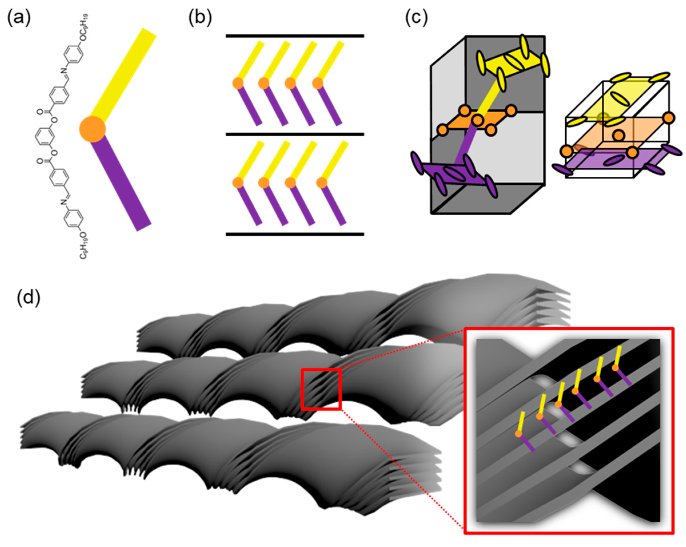
Figure 1. Formation of helical nanofilament (HNF) phase from bent-core LC molecules. (a) Chemical structure of typical bent-core LC molecule P-9-OPIMB (NOBOW). A center aromatic ring (orange) and two arm planes (yellow and purple) have three tilted planes within each molecule. (b) When cooled from an isotropic temperature, the NOBOW molecules form smectic layers. (c) Due to the three tilted planes in NOBOW, there is elastic stress within smectic layers, called an in-layer mismatch. The right panel represents the oblique herringbone lattices of each arm plane (yellow and purple circles) projected on to the center aromatic ring plane (orange circles). (d) In order to relieve the stress, layers are bent to be an HNF with saddle-splay curvature.
Crystals 10 00675 g001
Figure 2. Research on the structural color of HNF with a secondary twist model. (a) Chemical structure and thermal phase transition of P-n-OPIMB homologues. (b) A reflective spectrum of the droplets of each HNF, which is randomly oriented but has a secondary twisted superstructure. (c) XRD results of HNF showing a polycrystal-like ring pattern demonstrates randomly oriented HNF. Reprinted with permission from [49], Copyright 2014, Springer Nature.
Crystals 10 00675 g002
Figure 3. Two examples of the conventional methods to align HNFs. (a) When bent-core LC molecules mixed with rod-shaped nematic LC molecules are placed in a rubbed polyimide LC cell, HNFs were grown parallel to the rubbing direction. P represents a direction of polarization in each HNF. Reprinted with permission from [60], Copyright 2013 Wiley-VCH. (be) When bent-core LC molecules are placed between two SAM-treated glass substrate, the molecules and HNFs are aligned depending on the substrate’s surface energy. (b) F-OTS and (c) PEG 6/9 offer low and high surface energy to induce homeotropic and planar anchoring to the LC molecules, respectively. The rods inside the layer represent the projection image of bent-shaped molecules. (d) Parallel aligned and (e) vertically aligned HNFs are formed in each condition. Reprinted with permission from [61], Copyright 2013, Royal Society of Chemistry.
Crystals 10 00675 g003
Figure 4. (a) Two types of AAO made from different anodizing electrolytes: barrier type and porous type. (b) A schematic illustration shows a cross-section of porous-type AAO and four main parameters that determine the properties of porous-type AAO. Reprinted with permission from [63], Copyright 2014, American Chemical Society. (ce) Top-down feature of porous AAOs with different sizes of Dp. Reprinted with permission from [64], Copyright 2019, Wiley-VCH.
Crystals 10 00675 g004
Figure 5. SEM images of individually grown HNFs in each pore of AAO whose Dp is (a) 30 nm, (b) 60 nm, and (c) 80 nm. (Scale bar: 100 nm) Reprinted with permission from [35], Copyright 2014, National Academy of Sciences.
Crystals 10 00675 g005
Figure 6. (ac) 2D-GIXD results of uniaxially aligned HNFs in each AAO pore with pore diameter (Dp) variation. daao and Δχ refer to the Dp of each AAO pore and the and the full width at half maximum (FWHM) value of azimuthal angle deviation in (1,1) peak. (df) 3D model of individual HNF in each pore. s represents the normal layer direction of the smectic layer. (g) Herringbone-like lattice made of bent-core LC molecules and their 2D diffraction patterns. (h) Final diffraction pattern of vertically oriented HNFs in AAO film. Reprinted with permission from [35], Copyright 2014, National Academy of Sciences.
Crystals 10 00675 g006
Figure 7. (ac) Chemical structure of bent-core LC molecule and chiral dopants with opposite handedness. (d,e) Cross-sectional SEM images of HNFs in each AAO pore with different chiral dopants. Under different chiral dopant conditions, the handedness of HNFs is controlled following the chirality of the mixed dopant. CD spectra of (f) left-handed and (g) right-handed helix. To eliminate the effect of dichroism and birefringence, the sample stage was rotated during the measurement. The rotated degree and its CD results are expressed together. Reprinted with permission from [70], Copyright 2020, American Chemical Society.
Crystals 10 00675 g007
Figure 8. Schematic illustrations of the photoaligning process of the azobenzene molecules. (a) When azobenzene molecules are exposed to linearly polarized UV light, molecules are reoriented orthogonally to the applied linear polarization. (b) However, if azobenzene molecules are shined on with unpolarized UV light, the molecules change their orientation to the UV-shining direction. Reprinted with permission from [75], Copyright 2016, Springer Nature.
Crystals 10 00675 g008
Figure 9. Schematic illustrations of the photoaligning process of azobenzene containing bent-shaped molecules and the HNF made from them. (a) When HNFs are grown without UV light, they are randomly oriented. (b) However, if HNFs are made under UV-shining conditions, vertically oriented HNFs are formed. (c) Without UV exposure, LC molecules are randomly oriented. (d,e) However, once UV light is irradiated from top to bottom, molecules are photoisomerized first and then reoriented following the light-propagating direction. (f) Chemical structure of D-n molecules and their thermal phase transition. Reprinted with permission from [7], Copyright 2019, Springer Nature.
Crystals 10 00675 g009
Figure 10. (a) Cross-sectional SEM images and (b) 2D-GIXD results of UV-treated D-n homologues in their HNF phase. Reprinted with permission from [7], Copyright 2019, Springer Nature.
Crystals 10 00675 g010
Figure 11. (a,b) Chemical structure of bent-shaped LC (L-L) and L-ligand-treated GNP (Au1). (c) Sketch of the thermal phase transition of pure L-L and the mixture of L-L and Au1. (d) TEM image of pure L-L shows layered crystal and HNFs. (e) 1D-XRD results of L-L depending on the temperature. TEM images of (f) Au1 and (g) the mixture of L-L and Au1. Reprinted with permission from [45], Copyright 2019, Wiley-VCH.
Crystals 10 00675 g011
Figure 12. Templating applications of HNF to transfer its chirality to other achiral materials. (a) Schematic illustration of the helical assembly of achiral nematic LC phase on the HNF’s surface. (b) CD analysis of HNF/N mixture depending on the temperature. CD signal is amplified when 8CB is in its nematic phase. Reprinted with permission from [46], Copyright 2017, Wiley-VCH. (c) Sketch of chirality transfer from HNF to fluorescent dye molecules when they are co-aligned with N molecules. (d) glum of the mixture of HNF/N/dye with temperature variation. Reprinted with permission from [47], Copyright 2019, Wiley-VCH.
Crystals 10 00675 g012
Figure 13. (a) Schematic illustration of the fabricating process for a chiral polymeric network replicated from the HNF. The BC molecule and RMC are mixed to form the HNF phase. UV irradiation caused photopolymerization and made the polymeric network formed on the HNF’s surface (Stage 1). BC molecules are selectively washed out from the composite, leaving pure polymer (Stage 2). Achiral rod-shaped molecules are injected into the chiral polymer template, and the chirality is transferred to them from the polymer (Stage 3). (b) Schematic image of the polymeric network before (Stage 2) and after (Stage 3) removal of HNF. (c) CD spectra for each stage with opposite chiral domains. The inset graph shows enlarged image of the spectrum in the wavelength range of 300 to 350 nm in Stage 2. Reprinted with permission from [90], Copyright 2020, American Chemical Society.
Crystals 10 00675 g013
Figure 14. (a) Chemical structures of NOBOW and 5CB, which can form HNF and nematic phases. (b) 1D-XRD results of pure NOBOW (blue), pure 5CB (red), and the mixture of both molecules (purple). (ce) 2D-GIXD results of pure NOBOW, pure 5CB, and their mixture. (e) The mixture shows an unordinary diffraction pattern from nematic phase under multiple spatial confinements between HNF and AAO wall. Reprinted with permission from [39]. The Authors, some rights reserved; exclusive licensee American Association for the Advancement of Science. Distributed under a Creative Commons Attribution Noncommercial License 4.0 (CC BY-NC) http://creativecommons.org/licenses/by-nc/4.0/.
Crystals 10 00675 g014
Figure 15. Structural coloration from the uniformly oriented HNF film. (a) Reflective POM images of D-n series in their HNF phases. Only the UV-shined area showed the reflection color, and color changes as the linkage length of the dimer (n in D-n) increased. (b) Schematic illustration of light reflection of aligned HNFs when subjected to white light. (c) HNF films show a vivid reflection color when placed on a black background. (d) When they are placed above a white background, yellow chemical colors are mostly observed due to the scattering effect from the background. (e) A reflective spectrum of aligned HNF films. (f) Photographic images of viewing angle-dependent reflective color changes of D-5 film. Reprinted with permission from [7], Copyright 2019, Springer Nature.
Crystals 10 00675 g015
Figure 16. Chiral sensing applications of aligned D-9 film using optical rotation. Schematic illustration of the experimental setup of a chiral detecting tool and optical rotation of the polarized light when the solution (yellow cylinder) contains (a) (−) or (b) (+) chiral material, respectively. Depending on the chirality of the solution, the brightness of each chiral domain changes. Reprinted with permission from [20], Copyright 2019, Wiley-VCH.
Crystals 10 00675 g016