Article

Antiferroelectric Bent-Core Liquid Crystal for Possible High-Power Capacitors and Electrocaloric Devices

1
Department of Physics, Kent State University, Kent, OH 44242, USA
2
Chemical Physics Interdisciplinary Program, Advanced Materials and Liquid Crystal Institute, Kent State University, Kent, OH 44242, USA
3
Institute for Physics, Otto-von-Guericke-Universität Magdeburg, ANP, 39016 Magdeburg, Germany
4
Institute for Solid State Physics and Optics, Wigner Research Centre for Physics, P.O. Box 49, H-1525 Budapest, Hungary
*
Authors to whom correspondence should be addressed.
Crystals 2020, 10(8), 652; https://doi.org/10.3390/cryst10080652
Submission received: 7 July 2020 / Revised: 28 July 2020 / Accepted: 28 July 2020 / Published: 30 July 2020
(This article belongs to the Special Issue Bent-Shaped Liquid Crystals and Beyond)

Abstract

:
We present small-angle X-ray scattering, polarized optical microscopy and electric current measurements of a sulfur-containing bent-core liquid crystal material for characterization of the layer and director structures, thermally and electrically driven transitions between antiferroelectric and ferroelectric structures and switching properties. It was found that the material has polarization-modulated homochiral synclinic ferroelectric (SmCsPFmod), homochiral anticlinic antiferroelectric (SmCaPA) and racemic synclininc antiferroelectric (SmCsPA) structures that can be reversibly switched between each other either thermally and/or electrically. High switching polarization combined with softness of the liquid crystalline structure makes this compound a good candidate for applications in high-power capacitors and electrocaloric devices.

1. Introduction

Recent advances in wearable electronic devices drive the development of miniature chemical and electric sensors and miniature power and information storage devices. In particular, the personal health care industry requires reliable and robust pressure and voltage-specific sensors for monitoring blood circulation, heart activity and body temperature [1]. Electric energy storage is another area where soft organic ferroelectrics may find prospective applications for their flexibility and even semiconducting properties [2,3,4]. For instance, umbrella-shaped columnar liquid crystals have been shown to store information of unprecedented density due to the ability to address each molecular column separately [5]. Efficient and reliable energy storage is crucial in our society. Electrical energy can be stored either electro-chemically in batteries or electro-statically in capacitors. Batteries have high energy density (~50–200 Wh/kg) and low power density (~1–1000 W/kg), while electro-static capacitors, have energy densities less than 0.1 Wh/kg and power densities over 5000 W/kg [6]. The gap between batteries and capacitors has been partially bridged with super-capacitors, which are currently being utilized in power conditioning and electric transportation, although they still have an order of magnitude smaller energy densities than batteries and take longer time to charge and discharge than conventional capacitors [7,8,9]. Capacitors made of antiferroelectric materials that undergo a reversible thermal or electric-field-induced transition to a ferroelectric state have the potential to store as much energy as electrochemical capacitors while maintaining the advantages of traditional capacitors [10,11].
Bent-core liquid crystals (BCLC) [12,13,14,15,16,17,18,19,20] often have a ferroelectric (FE) [21,22,23] or antiferroelectric (AF) smectic phase [24,25,26,27,28] with permanent polarization up to P~10−2 C/m2 [14] that can be switched with E~10 V/µm fields as quickly as t~10 µs. Although the specific stored energy in such a device is of order of 0.2 Wh/kg, it is considerably lower than in batteries. Their power density w/t can be as high as 107–108 W/kg—i.e., much higher than of the current dielectric capacitors.
Especially interesting are those AF BCLC materials that have both antiferroelectric and ferroelectric (FE) phases with reversible AF-FE phase transitions [29,30,31,32], as the phase transition is accompanied by the electric energy generation of dissipation that can be used in electro-caloric [33] applications (cooling or heating). Assuming a phase transition happening within a less than 1 K temperature range, the isothermal entropy change can be more than 100 Jkg−1 K−1.
In this paper we describe the phase behavior, nanostructures and electric properties of a sulfur containing bent-core material B-10(S) with Ferroelectric (FE) Smectic–Antiferroelectric (AF) Smectic phase transition. Our X-ray, Polarized Optical Microscopy (POM) studies, polarization current and electro-optical measurements clarify the nanostructure and electric properties of the FE and AF phases. Based on these results, they have the potential for energy storage and electrocaloric applications.

2. Materials and Methods

The molecular structure of B-10(S) is shown at the top of Figure 1a. The synthesis and the preliminary (without X-ray studies) phase assignment of this material was reported by Heppke et al., was given as Cr 112 °C, B3 133.7 °C, B7 148.3 °C Iso [34,35]. Here, the B7 structure is characterized by a birefringent “telephone-wire type texture” that grows by cooling into the isotropic fluid [36] and is identified later as a polarization-modulated smectic or columnar phase [37,38]. The B3 phase is a higher-ordered or crystalline smectic phase [17].
Small angle X-ray scattering (SAXS) measurements were carried out at beamline 7.3.3 of the Advanced Light Source (ALS) at Lawrence Berkeley Laboratory with 10 KeV X-ray energy. B-10(S) was loaded in 2 mm dimeter quartz capillaries and placed in customized Instec hot stage, allowing us to apply a 1.5 Tesla magnetic field on the sample for alignment. Two-dimensional SAXS patterns were recorded by a Pilatus 2M detector (Dectris, Inc., Baden, Switzerland) at a 2.068 m distance from the sample. The beam center and the sample-to-detector distance were calibrated using silver behenate. The material was heated to isotropic phase and cooled slowly though all liquid crystal phases to the crystal phase.
Electro-optical and polarization current measurements were carried out in 4 μm thick films, where B–10(S) was sandwiched between transparent indium tin oxide (ITO) electrodes overcoated with rubbed polyimide alignment layers. The sandwich cells were placed in Instec HS2000 heat stage and viewed through an Olympus BX60 polarizing microscope equipped with crossed polarizers. The electric signals were applied by a HP 33120A function generator and amplified by a FLC E20AD voltage amplifier.
Ferroelectric polarization and switching time measurements were carried out by monitoring the time dependence of the electric current flowing through B-10(S) with the A = 25 mm2 active area under triangular and rectangular wave voltages at various frequencies. The time dependence of the applied and measured voltages V (t) and V m(t) were monitored by an InfiniVision MSO-X 302A mixed signal oscilloscope. Prior to measurements, the material was treated by a large (~20 V/µm) low frequency (~12 Hz) rectangular wave voltage that aligned all the layers parallel to the electric field. That alignment remained stable as long as the material was not heated to the isotropic phase or was not cooled to the crystal phase. Applying a triangular waveform, where the voltage is proportional to the time in each half period, allows for accurate measurements of the switching polarization, since the response of the rest of the cell is linear, proportional to the electric conductivity. The value of the polarization P is calculated from the integral area of the measured voltage peak V m p above a background line V ( t ) R s / R L C dropped under a resistance Rs (Rs << RLC), connected in series with the liquid crystal as P = ( V m p ( t ) d t ) / ( 2 R s A ) [39]. There are one and two peaks in one half period of the triangular wave voltage for ferroelectric and antiferroelectric phases, respectively. The threshold voltage for switching is determined by the voltage where the polarization peak appears. The current response to the square-waveform enables accurate measurements of the switching time. On poling, the polarization follows the constant external field applied to the cell. This simplifies the description of the switching process and gives the switching time, as well as its dependence, on the field strength. The switching times are determined from the peak positions of the current peaks that appear after switching rectangular wave voltage.

3. Results and Discussion

The SAXS results are summarized in Figure 1a–d. No diffraction peaks were observed above 150 °C, showing its 3-D fluid nature.
As shown in Figure 1b, between 150 °C and 125 °C, several rings appear in the 0.05–0.5 Å−1 q-range. The strongest temperature independent peak at q(10)~0.149 Å−1 and its two harmonics at q(20) = 2q(10) and q(30) = 3q(10) indicate a layer structure with periodicity d = 2π/q1 = 40.21 Å. Considering that the length of the symmetrically bent molecule is L = 54 Å, the tilt angle θ, assuming no intercalation between the terminal chains of the neighbor molecules, can be calculated as θ = arccos ( d L ) 42 ° . Allowing some interdigitation, this angle can be smaller, but considering the length of the terminal chains, it cannot be zero, even for complete interdigitation. Additionally, there are temperature dependent peaks in the 0.01 < θ < 0.06 Å−1 range. The main peak at q(01)~0.015 Å−1 and its four harmonics show layer undulations with periodicities pm increasing from 330 Å at 147 °C to 420 Å at 127 °C (seen separately in Figure 1c). Such tilted smectic phases with undulated layers agree with the structural assignment of the B7 phase [37,40]. The layer undulations disappear below 125 °C, where only the weakly temperature dependent peaks appear at q(10) ~0.128 Å−1 and at harmonics q(i,0) = i·q(10) (I = 2–4) corresponding to a layer spacing of d = 2π/q1 = 48.8 Å (see Figure 1d). Such periodicity, assuming some degree of interdigitation between the terminal chains, indicates a fluid tilted smectic phase with tilt angle θ < 25°. Such a structure is not compatible to the B3 phase assignment with in-plane or crystalline order that would lead to peaks with other periodicities. Below 115 °C, with about a 5 °C overlap, another smectic phase without in-plane order is observed, as seen in Figure 1e. The peaks at q(10)~0.122 Å−1 and its harmonics with q(i,0) = i·q(10) (I = 2–4) correspond to a layer periodicity of d = 2π/q1 = 50.12 Å. Depending on the interdigitation by the terminal chains, this could correspond to a tilted smectic phase with a tilt angle of up to θ = 20° or to an orthogonal (SmA) smectic phase. For the time being, we call it an SmX phase.
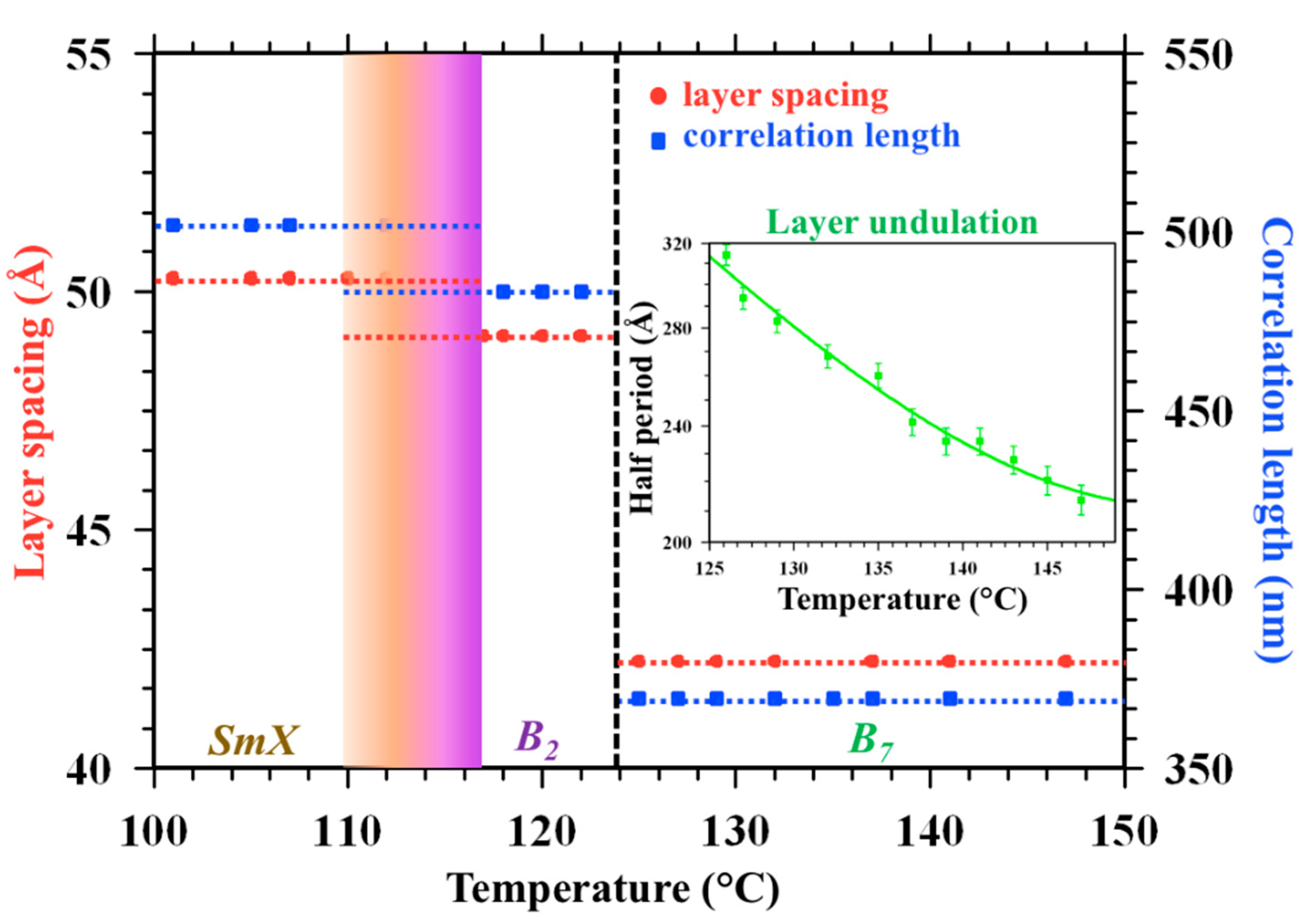
The temperature dependences of the layer spacing d and correlation length ξ are calculated from the first harmonic wavenumber peak q(10), as d = 2p/q(10) and from the full width at half maxima (FWHM). The correlation length ξ is proportional to the inverse of FWHM. The order of magnitude and the temperature dependence of the correlation length is plotted against the right axis, assuming the proportionality constant is 1. The temperature dependence of the layer spacing is plotted against the left axis of Figure 2. The shaded area between the B2 and SmX phases indicates phase overlap due to the first order nature of the transition. Although wide angle X-ray scattering would be needed to find out if the SmX phase has an in-plane order or not, the strongly first order transition between the B2 and SmX phases indicate it has in-plane order. The inset shows the half periodicity of the layer undulation measured in the B7 phase. While the layer periodicities d = 40.21, 48.8 and 50.12 Å and the correlation lengths ξ = 370, 483 and 502 nm are basically constant in the B7, B2 and SmX phases, respectively, the periodicity of the in-layer modulation in the B7 phase is clearly increasing on cooling.
Temperature dependence of the voltage threshold for switching, together with representative electric current waveforms (in inset) in the B7 and B2 phases are shown in Figure 3. At and above 125 °C, a ferroelectric type switching is seen with a threshold field of Eth ≈ 10.5 V/µm (one current peak in each half period of the triangular wave voltage, as seen in the inset at 127 °C), which is basically constant in the entire B7 phase range. Based on this and the SAXS results, we denote this as an SmCPFmod phase, where SmC stands for tilted smectic phase, P refers to the polar nature of the phase and F in the subscript denotes ferroelectric switching and “mod” describes the modulated layer structure. Below 125 °C in the B2 phase the electric current under triangular wave voltage has a double peak in each half period (see the time dependence of the electric current at 118 °C in the inset), corresponding to an antiferroelectric tilted smectic (SmCPA) phase. In this phase the threshold field decreases continuously to Eth ≈ 3.5 V/µm. Below 115 °C, no polarization peak can be observed even up to 20 V/µm fields, indicating a paraelectric or dielectric nature of the phase.
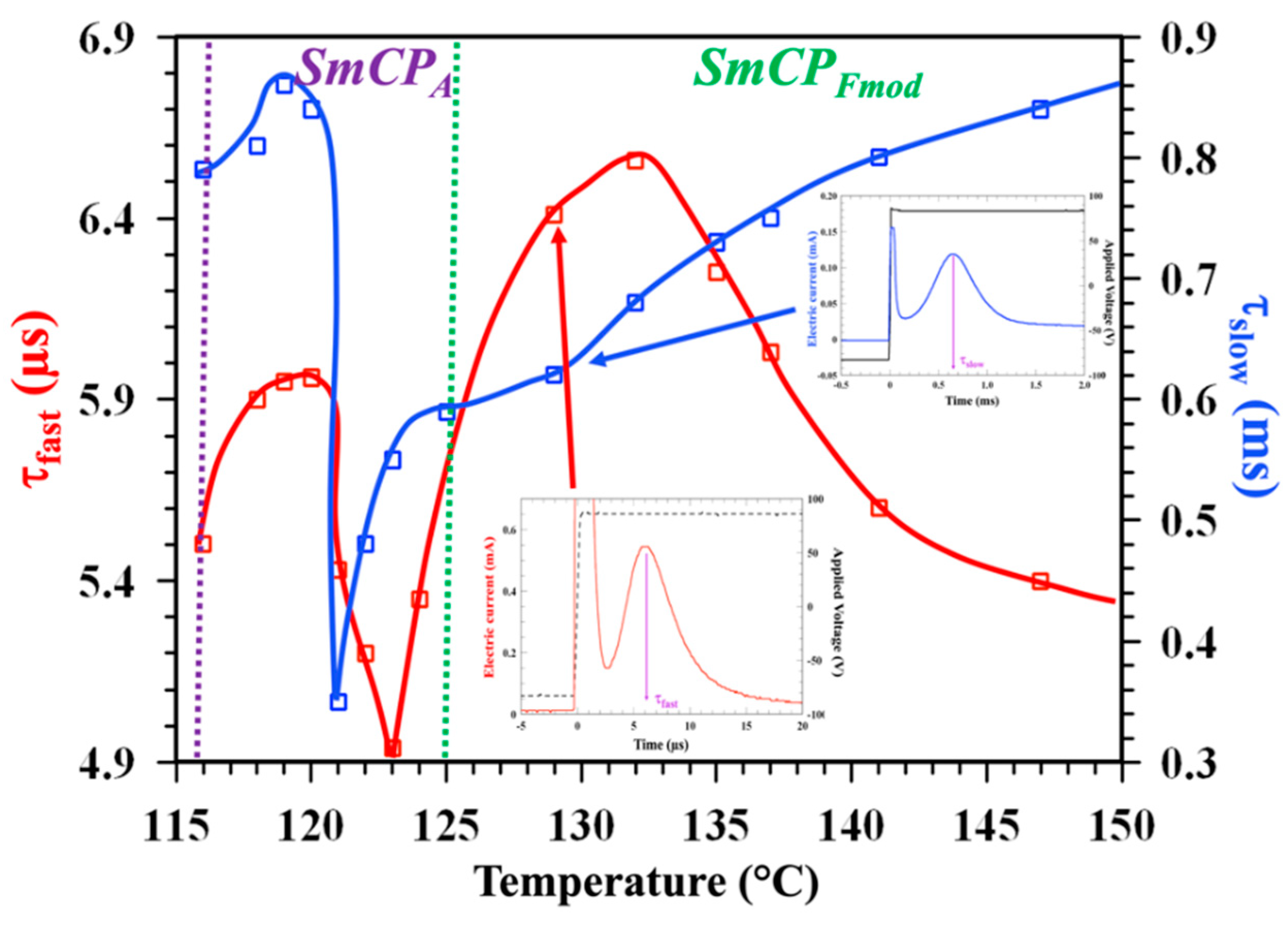
Electric current measurements under rectangular voltage waveforms (see Figure 4) reveal two peaks in both the SmCPFmod and SmCPA phase ranges. The slow peak is in the 0.5–0.9 ms range, while the fast one with 5–6 µs range. The integral areas below these peaks, however, are very different in these two phases: the slow peak is dominating in the ferroelectric SmCPFmod range, while the fast peak area is much larger in the antiferroelectric SmCPA phase. These behaviors are very similar to that observed and explained for a Fluorine containing bent-core material [29]. The presence of two peaks indicates a coexistence of chiral and racemic domains in both phases. From the ratios of the integral areas (see Figure 5) we can see that about 80% of the material in the SmCPFmod state has synclinic chiral structure (SmCsPFmod). This ratio reverses as the material is cooled to the SmCPA phase, where over 80% of the material appears to be in the racemic synclinic SmCsPA state. It is known that switching the polarization while retaining homo-chirality requires rotation around the tilt cone, whereas in the racemic state it can be done by rotation around the long axis, which is much faster than the rotation around the tilt cone [14].
The temperature dependence of the polarization, as calculated from the areas below the current peaks, are shown in Figure 5. Triangular symbols indicate the values measured under triangular wave voltages and rectangular symbols correspond to data extracted from the measurements under rectangular voltage waveform. Open rectangles correspond to the areas of the slow (blue) and fast (red) peaks, while solid black rectangles are the sum of these two areas. The total polarization values in the Sm CPFmod phase increase weakly on cooling from 140n C/cm2 to about 170n C/cm2, then jump up to 240n C/cm2 in the B2 phase. The value of the polarization drops quickly upon the first-order transition to the Sm A phase. We note that each polarization measurements took only a few seconds and between two temperatures the material was cooled without field to prevent long-term structural transformations.
Although the dominating slow switching in the SmCPFmod phase and the mainly fast switching in the SmCPA phase have already indicated that the tilt is mainly synclinic in both phases, we also carried out electro-optical investigations to verify this independently. Representative POM textures and their schematic director and layer structures are summarized in Figure 6 and Figure 7 for the SmCPFmod and SmCPA phases, respectively.
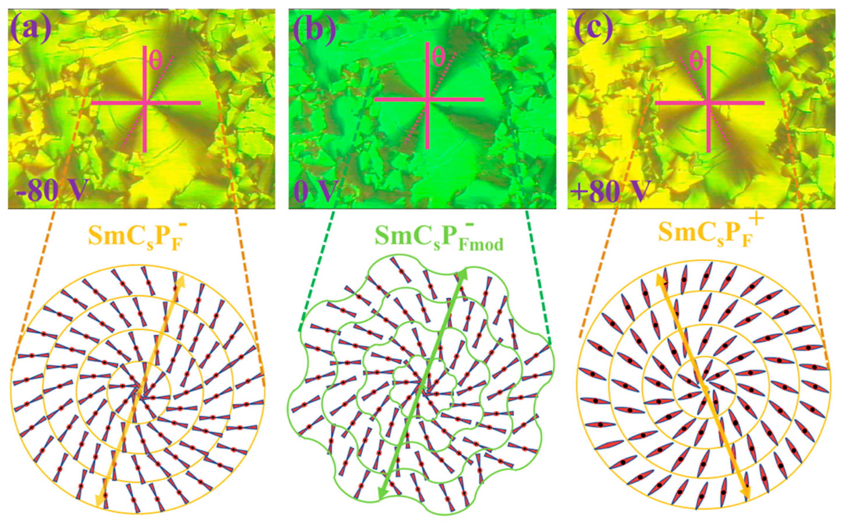
Figure 6a shows the texture at 127 °C in the field-induced SmCPF- state under −80 V applied across the cell. The central area shows Maltese crosses rotated by about 30–35° with respect to the vertical and horizontal polarizers. The cross-section of the director and layer structure in the plane of the substrates is illustrated below the image. The smectic layers form concentric cylinders with a defect in the middle of the Maltese cross. The director is tilted uniformly (synclinic structure) with respect to the layer normal to the left by angle q; thus, it is parallel to the polarizers at an angle −θ. The yellowish-green birefringence color corresponds to an optical path difference Δ n d 800 nm, corresponding to a birefringence Δ n 0.2 . After turning the field OFF, the direction of the Maltese crosses remains unchanged, indicating bistability. Only the birefringence color shifts toward green with optical path difference Δ n d 750 nm, corresponding to a birefringence Δ n 0.188 . As illustrated in the director and layer structure below, this is due to the modulated layer structure both along and normal to the substrates. This causes the inhomogeneity of the director structure, explaining the decreased effective birefringence. On applying +80 V, the Maltese crosses rotated by about 70°—i.e., by twice the tilt angle. This is the consequence of the switching of the polarization to the opposite direction, as shown in Figure 6c. The birefringence color again shifts to yellowish green, indicating the field induced SmCPFmod to SmCPF transition, as observed on other bent-core materials, as well [41]. Based on these observations, we verify that this layer-modulated tilted smectic phase is synclinic SmCsPFmod—i.e., homochiral [19].
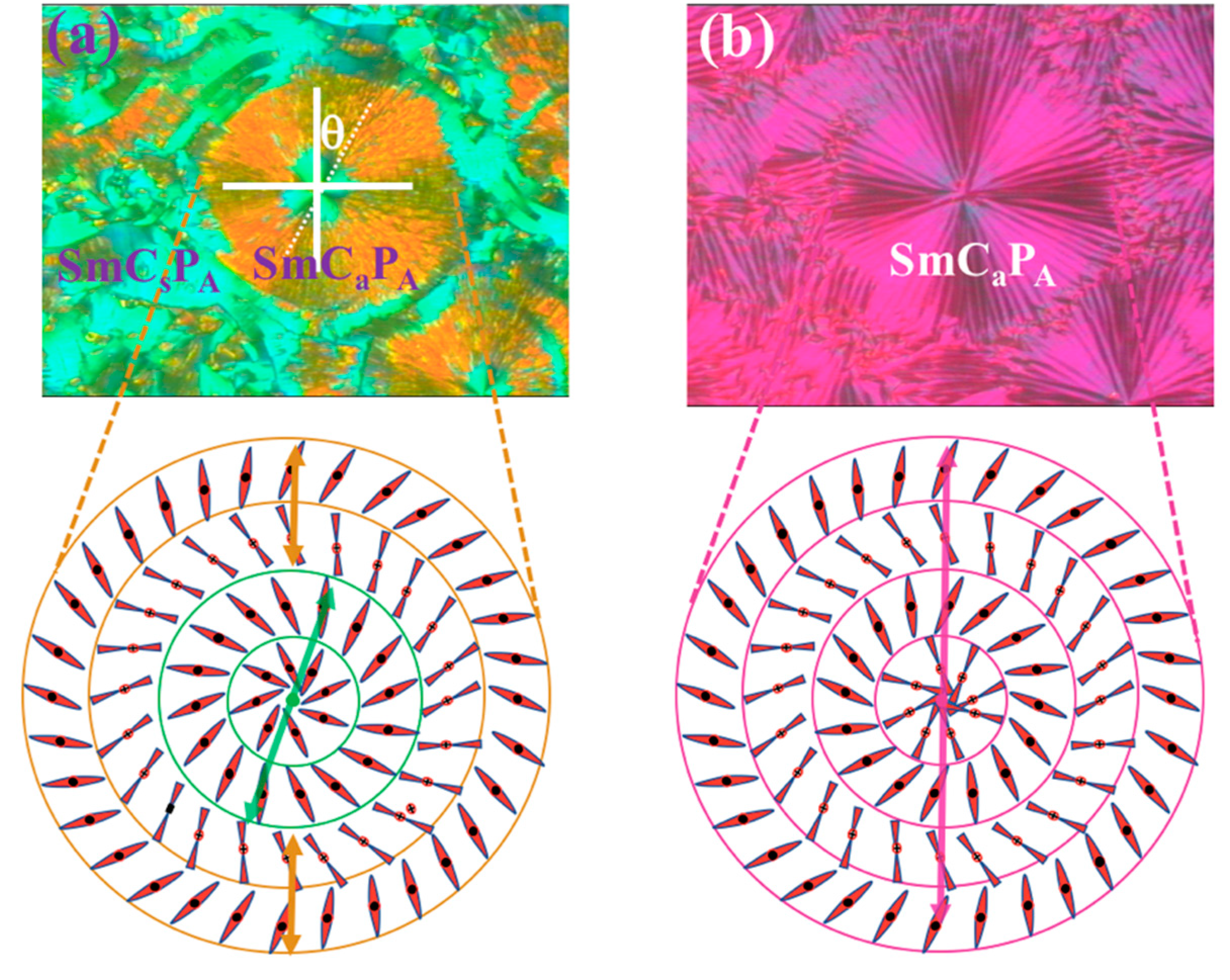
After cooling to the antiferroelectric SmCPA phase at zero electric field, two different types of domains appear in Figure 7a. One is characterized by a turquoise (“Tiffany blue”) birefringent color with Δ n d 700 nm ( Δ n 0.175 ), the other one has orange color with Δ n d 450 nm( Δ n 0.11 ). The director and layer structure of these domains are shown below the texture. The turquoise domain in the center is synclinic antiferroelectric (SmCsPA)—i.e., racemic [19] as our switching time measurements indicated above, while the minority outside orange area is anticlinic (SmCaPA)—i.e., homochiral. In the approximation that the birefringence is much smaller than the ordinary refractive index (ns << no), the effective birefringence of an anticlinic state can be given as Δ n a Δ n s cos 2 ( 2 θ ) [42], which with the synclinic Δ n s 0.18 value gives the measured Δna ≈ 0.11 for θ~20°. This value agrees with the estimated θ < 25° tilt angle from the layer periodicities by SAXS measurements, shown in Figure 2 and indicates some interdigitation between terminal chains of molecules in neighbor layers.
Representative textures and schematics of the corresponding director and layer structure of the central circularly shaped domain after driving by 12 V/µm, f = 12 Hz square wave field for a few minutes, are shown in Figure 7b. The birefringence color is uniformly purple with Maltese crosses parallel to the crossed polarizers, indicating an anti-clinic antiferroelectric (homochiral) structure everywhere. Such a rectangular electric-field-induced racemic to chiral phase transformation is already found and explained for other bent-core materials [43]. The increased optical path difference n·d ≈ 550 nm means an effective birefringence of Δna ≈ 0.138, which with θ ≈ 20° gives Δns ≈ 0.234. This value is much larger than that observed after cooling at zero field, indicating that the smectic layers were tilted upon cooling at zero field and became upright after applying the large field. The birefringence of the SmCsPA structure with upright layers is also larger than of the field induced SmCsPF structure in the higher temperature phase range, which is consistent with the increasing birefringence (decreased director fluctuations) toward lower temperatures.

4. Conclusions

In this paper we have characterized the nanostructures, the thermally and electrically driven transitions, between antiferroelectric and ferroelectric structures and the switching properties of a sulfur containing bent-core liquid crystal material. It was found that the material has polarization-modulated ferroelectric (SmCPFmod) and antiferroelectric (SmCsPA) structures that can be switched between one another either thermally and/or electrically. Fast sub-millisecond reversible switching between antiferroelectric and ferroelectric states with up to P = 2.4 mC/m2 polarization provides a charging capacity with as high as a 30 kW/kg power density. Such power density makes this material comparable to state-of-the-art electronic double layer capacitors. [9] The modulated structure of the ferroelectric phase (SmCsPFmod) allows for the stabilization of the polar domains at a modulation scale of 50 nm. Piezo and pyroelectric properties of ferroelectric bent-core liquid crystals also make them promising for sensor applications as touch and pressure sensors [44]. Although with the present materials these features can be achieved only at elevated temperatures, the recent development of wide temperature range (from −40 °C to +80 °C) antiferroelectric bent-core liquid crystal mixtures [45,46] may make such high power density storage devices a realm of the near future. An added advantage of the material studied here is the thermally induced antiferroelectric–ferroelectric transitions, that may offer their use in electro-caloric devices with over 100 Jkg−1K−1 isothermal entropy change either at the Iso–SmCPsFmod or the SmCPA–SmCPsFmod phase transitions. This value is larger than those found in dielectric liquid crystals [47].

Author Contributions

Conceptualization, A.E. and A.J.; methodology, A.J.; investigation, R.S., C.F. and A.J.; resources, A.E.; writing—original draft preparation, R.S. and A.J.; writing—review and editing, A.E., C.F.; All authors have read and agreed to the published version of the manuscript.

Funding

This research was funded by the National Science Foundation under grant DMR–1904167. The use of Beamlines 7.3.3 was supported by the Advanced Light Source supported by the Director of the Office of Science, Office of Basic Energy Sciences, of the U.S. Department of Energy under contract no. DE-AC02–05CH11231. A.E. acknowledges the support of Deutsche Forschungsgemeinschaft DFG, project ER 467/8–2.

Acknowledgments

We appreciate useful discussions with Chenhui Zhu at ALS and thank G. Heppke and H. Sawada for providing the material B–10(S) for us.

Conflicts of Interest

The authors declare no conflict of interest.

References

  1. Park, J.; Lee, Y.; Ha, M.; Cho, S.; Ko, H. Micro/nanostructured surfaces for self-powered and multifunctional electronic skins. J. Mater. Chem. B 2016, 4, 2999–3018. [Google Scholar] [CrossRef] [PubMed]
  2. Lee, Y.; Park, J.; Cho, S.; Shin, Y.-E.; Lee, H.; Kim, J.; Myoung, J.; Cho, S.; Kang, S.; Baig, C.; et al. Flexible Ferroelectric Sensors with Ultrahigh Pressure Sensitivity and Linear Response over Exceptionally Broad Pressure Range. ACS Nano 2018, 12, 4045–4054. [Google Scholar] [CrossRef] [PubMed]
  3. Muralt, P. Ferroelectric thin films for micro-sensors and actuators: A review. J. Micromech. Microeng. 2000, 10, 136–146. [Google Scholar] [CrossRef]
  4. Varga, M.; Morvan, J.; Diorio, N.; Buyuktanir, E.; Harden, J.; West, J.L.; Jákli, A. Direct piezoelectric responses of soft composite fiber mats. Appl. Phys. Lett. 2013, 102, 153903. [Google Scholar] [CrossRef] [Green Version]
  5. Miyajima, D.; Araoka, F.; Takezoe, H.; Kim, J.; Kato, K.; Takata, M.; Aida, T. Ferroelectric Columnar Liquid Crystal Featuring Confined Polar Groups Within Core-Shell Architecture. Science 2012, 336, 209–213. [Google Scholar] [CrossRef]
  6. Basic Research Needs for Electrical Energy Storage. Available online: https://www.chem.uci.edu/~lawm//Basic%20Research%20Needs%20for%20Electrical%20Energy%20Storage.pdf (accessed on 7 July 2020).
  7. Parfomak, P.W. Energy Storage Technologies for Power Grids and Electric Transportation. Available online: http://abaque.com.br/wp-content/uploads/2017/07/R42455.pdf (accessed on 7 July 2020).
  8. Zhang, S.; Pan, N. Supercapacitors Performance Evaluation. Adv. Energy Mater. 2014, 5, 1401401. [Google Scholar] [CrossRef] [Green Version]
  9. Shao, Y.; El-Kady, M.F.; Sun, J.; Li, Y.; Zhang, Q.; Zhu, M.; Wang, H.; Dunn, B.; Kaner, R.B. Design and Mechanisms of Asymmetric Supercapacitors. Chem. Rev. 2018, 118, 9233–9280. [Google Scholar] [CrossRef]
  10. Young, S.E. Thermally and Electrically Induced Antiferroelectric ↔ Ferroelectric Transition in Perovskite Ceramics for Use in High Energy Density Capacitors. Available online: http://citeseerx.ist.psu.edu/viewdoc/download?doi=10.1.1.843.8633&rep=rep1&type=pdf (accessed on 7 July 2020).
  11. Chauhan, A.; Patel, S.; Vaish, R.; Bowen, C.R. Anti-Ferroelectric Ceramics for High Energy Density Capacitors. Materials 2015, 8, 8009–8031. [Google Scholar] [CrossRef] [Green Version]
  12. Takezoe, H.; Eremin, A. Bent-Shaped Liquid Crystals—Structures and Physical Properties, 1st ed.; Taylor & Francis: Boca Raton, FL, USA, 2017. [Google Scholar]
  13. Takezoe, H.; Takanishi, Y. Bent-Core Liquid Crystals: Their Mysterious and Attractive World. Jpn. J. Appl. Phys. 2006, 45, 597–625. [Google Scholar] [CrossRef]
  14. Eremin, A.; Jákli, A. Polar bent-shape liquid crystals—From molecular bend to layer splay and chirality. Soft Matter 2013, 9, 615–637. [Google Scholar] [CrossRef]
  15. Jákli, A.; Lavrentovich, O.D.; Selinger, J.V. Physics of liquid crystals of bent-shaped molecules. Rev. Mod. Phys. 2018, 90, 045004. [Google Scholar] [CrossRef] [Green Version]
  16. Tschierske, C.; Dantlgraber, G. From antiferroelectricity to ferroelectricity in smectic mesophases formed by bent-core molecules. Pramana 2003, 61, 455–481. [Google Scholar] [CrossRef]
  17. Pelzl, G.; Diele, S.; Weissflog, W. Banana-Shaped Compounds—A New Field of Liquid Crystals. Adv. Mater 1999, 11, 707–724. [Google Scholar] [CrossRef]
  18. Ros, M.B.; Serrano, J.L.; De La Fuente, M.R.; Folcia, C.L. Banana-shaped liquid crystals: A new field to explore. J. Mater. Chem. 2005, 15, 5093. [Google Scholar] [CrossRef]
  19. Link, D.R.; Natale, G.; Shao, R.; MacLennan, J.E.; Clark, N.A.; Körblova, E.; Walba, D.M. Spontaneous Formation of Macroscopic Chiral Domains in a Fluid Smectic Phase of Achiral Molecules. Science 1997, 278, 1924–1927. [Google Scholar] [CrossRef]
  20. Reddy, R.A.; Tschierske, C. Bent-core liquid crystals: Polar order, superstructural chirality and spontaneous desymmetrisation in soft matter systems. J. Mater. Chem. 2006, 16, 907–961. [Google Scholar] [CrossRef]
  21. Bedel, J.P.; Rouillon, J.C.; Marcerou, J.-P.; Laguerre, M.; Nguyen, H.T.; Achard, M.F. Novel mesophases in fluorine substituted banana-shaped mesogens. Liq. Cryst. 2000, 27, 1411–1421. [Google Scholar] [CrossRef]
  22. Walba, D.M. A Ferroelectric Liquid Crystal Conglomerate Composed of Racemic Molecules. Science 2000, 288, 2181–2184. [Google Scholar] [CrossRef]
  23. Reddy, R.A.; Sadashiva, B.K. Ferroelectric properties exhibited by mesophases of compounds composed of achiral banana-shaped molecules. J. Mater. Chem. 2002, 12, 2627–2632. [Google Scholar] [CrossRef]
  24. Keith, C.; Reddy, R.A.; Hauser, A.; Baumeister, U.; Tschierske, C. Silicon-Containing Polyphilic Bent-Core Molecules: The Importance of Nanosegregation for the Development of Chirality and Polar Order in Liquid Crystalline Phases Formed by Achiral Molecules. J. Am. Chem. Soc. 2006, 128, 3051–3066. [Google Scholar] [CrossRef]
  25. Keith, C.; Dantlgraber, G.; Reddy, R.A.; Baumeister, U.; Tschierske, C. Ferroelectric and Antiferroelectric Smectic and Columnar Liquid Crystalline Phases Formed by Silylated and Non-Silylated Molecules with Fluorinated Bent Cores. Chem. Mater. 2007, 19, 694–710. [Google Scholar] [CrossRef]
  26. Kumazawa, K.; Nakata, M.; Araoka, F.; Takanishi, Y.; Ishikawa, K.; Watanabe, J.; Takezoe, H. Important role played by interlayer steric interactions for the emergence of the ferroelectric phase in bent-core mesogens. J. Mater. Chem. 2004, 14, 157–164. [Google Scholar] [CrossRef]
  27. Eremin, A.; Diele, S.; Pelzl, G.; Nadasi, H.; Weissflog, W.; Salfetnikova, J.; Kresse, H. Experimental evidence for an achiral orthogonal biaxial smectic phase without in-plane order exhibiting antiferroelectric switching behavior. Phys. Rev. E 2001, 64, 051707. [Google Scholar] [CrossRef] [PubMed]
  28. Jakli, A.; Rauch, S.; Lötzsch, D.; Heppke, G. Uniform textures of smectic liquid-crystal phase formed by bent-core molecules. Phys. Rev. E 1998, 57, 6737–6740. [Google Scholar] [CrossRef]
  29. Rauch, S.; Bault, P.; Sawade, H.; Heppke, G.; Nair, G.G.; Jákli, A. Ferroelectric-chiral–antiferroelectric-racemic liquid crystal phase transition of bent-shape molecules. Phys. Rev. E 2002, 66, 021706. [Google Scholar] [CrossRef] [PubMed] [Green Version]
  30. Umadevi, S.; Jakli, A.; Sadashiva, B.K. Odd-even effects in bent-core compounds containing terminal n-alkyl carboxylate groups. Soft Matter 2006, 2, 875–885. [Google Scholar] [CrossRef] [PubMed]
  31. Kohout, M.; Chambers, M.; Vajda, A.; Galli, G.; Domján, A.; Svoboda, J.; Bubnov, A.; Jákli, A.; Fodor-Csorba, K. Properties of non-symmetric bent-core liquid crystals with variable flexible chain length. Liq. Cryst. 2010, 37, 537–545. [Google Scholar] [CrossRef]
  32. Reddy, R.A.; Baumeister, U.; Keith, C.; Hahn, H.; Lang, H.; Tschierske, C. Influence of the core structure on the development of polar order and superstructural chirality in liquid crystalline phases formed by silylated bent-core molecules: Lateral substituents. Soft Matter 2007, 3, 558–570. [Google Scholar] [CrossRef]
  33. Mischenko, A.S.; Zhang, Q.; Scott, J.F.; Whatmore, R.W.; Mathur, N.D. Giant Electrocaloric Effect in Thin-Film PbZr0.95Ti0.05O3. Science 2006, 311, 1270–1271. [Google Scholar] [CrossRef] [Green Version]
  34. Heppke, G.; Parghi, D.D.; Sawade, H. Novel sulphur-containing banana-shaped liquid crystal molecules. Liq. Cryst. 2000, 27, 313–320. [Google Scholar] [CrossRef]
  35. Heppke, G.; Parghi, D.D.; Sawade, H. Investigations on Novel Sulphur-Containing “Banana-Shaped” Liquid Crystals. Mol. Cryst. Liq. Cryst. Sci. Technol. Sect. A Mol. Cryst. Liq. Cryst. 2000, 352, 311–318. [Google Scholar] [CrossRef]
  36. Pelzl, G.; Diele, S.; Jákli, A.; Lischka, C.; Wirth, I.; Weissflog, W. Preliminary communication Helical superstructures in a novel smectic mesophase formed by achiral banana-shaped molecules. Liq. Cryst. 1999, 26, 135–139. [Google Scholar] [CrossRef]
  37. Coleman, D.A.; Fernsler, J.; Chattham, N.; Nakata, M.; Takanishi, Y.; Körblová, E.; Link, D.R.; Shao, R.-F.; Jang, W.G.; MacLennan, J.E.; et al. Polarization-Modulated Smectic Liquid Crystal Phases. Science 2003, 301, 1204–1211. [Google Scholar] [CrossRef] [PubMed] [Green Version]
  38. Pelzl, G.; Diele, S.; Jákli, A.; Weissflog, W. The mysterious B7 phase: From its discovery up to the present stage of research. Liq. Cryst. 2006, 33, 1513–1523. [Google Scholar] [CrossRef]
  39. Miyasato, K.; Abe, S.; Takezoe, H.; Fukuda, A.; Kuze, E. Direct Method with Triangular Waves for Measuring Spontaneous Polarization in Ferroelectric Liquid Crystals. Jpn. J. Appl. Phys. 1983, 22, L661–L663. [Google Scholar] [CrossRef]
  40. Coleman, D.A. Effects of the Spontaneous Polarization on the Structural and Dynamic Properties of Ferroelectric Liquid Crystals. Available online: http://www.e-lc.org/dissertations/tmp/David_A_Coleman,_,_2009_09_01_22_06_24.pdf (accessed on 7 July 2020).
  41. Nakata, M.; Link, D.R.; Takanishi, Y.; Takahashi, Y.; Thisayukta, J.; Niwano, H.; Coleman, D.; Watanabe, J.; Iida, A.; Clark, N.A.; et al. Electric-Field-Induced Transition in Polarization Modulated Phase Studied Using Microbeam X-ray Diffraction. Phys. Rev. 2005, 71, 011705. [Google Scholar]
  42. De Meyere, A.; Maximus, B.; Fornier, J.; Verweire, B. Geometrical Averaging of AFLC Dielectric Tensors. Mol. Cryst. Liq. Cryst. Sci. Technol. Sect. A Mol. Cryst. Liq. Cryst. 1998, 317, 99–110. [Google Scholar] [CrossRef]
  43. Heppke, G.; Jákli, A.; Rauch, S.; Sawade, H. Electric-field-induced chiral separation in liquid crystals. Phys. Rev. E 1999, 60, 5575–5579. [Google Scholar] [CrossRef] [Green Version]
  44. Jákli, A.; Éber, N. Soft materials for linear electromechanical energy conversion. Curr. Opin. Chem. Eng. 2013, 2, 120–124. [Google Scholar] [CrossRef] [Green Version]
  45. Wang, J.; Bergquist, L.; Hwang, J.-I.; Kim, K.-J.; Lee, J.-H.; Hegmann, T.; Jákli, A. Wide temperature-range, multi-component, optically isotropic antiferroelectric bent-core liquid crystal mixtures for display applications. Liq. Cryst. 2017, 45, 333–340. [Google Scholar] [CrossRef]
  46. Bergquist, L.; Zhang, C.; De Almeida, R.R.R.; Pellegrene, B.; Salamończyk, M.; Kim, M.; Hwang, J.; Kim, K.-J.; Lee, J.; Jákli, A.; et al. An Optically Isotropic Antiferroelectric Liquid Crystal (OI-AFLC) Display Mode Operating over a Wide Temperature Range using Ternary Bent-Core Liquid Crystal Mixtures. ChemistryOpen 2017, 6, 196–200. [Google Scholar] [CrossRef] [PubMed]
  47. Qian, X.-S.; Lu, S.G.; Li, X.; Gu, H.; Chien, L.-C.; Zhang, Q. Large Electrocaloric Effect from Electrical Field Induced Orientational Order-Disorder Transition in Nematic Liquid Crystals Possessing Large Dielectric Anisotropy. In Proceedings of the MRS Proceedings; Cambridge University Press (CUP): Cambridge, UK, 2013; Volume 1543, pp. 13–20. [Google Scholar]
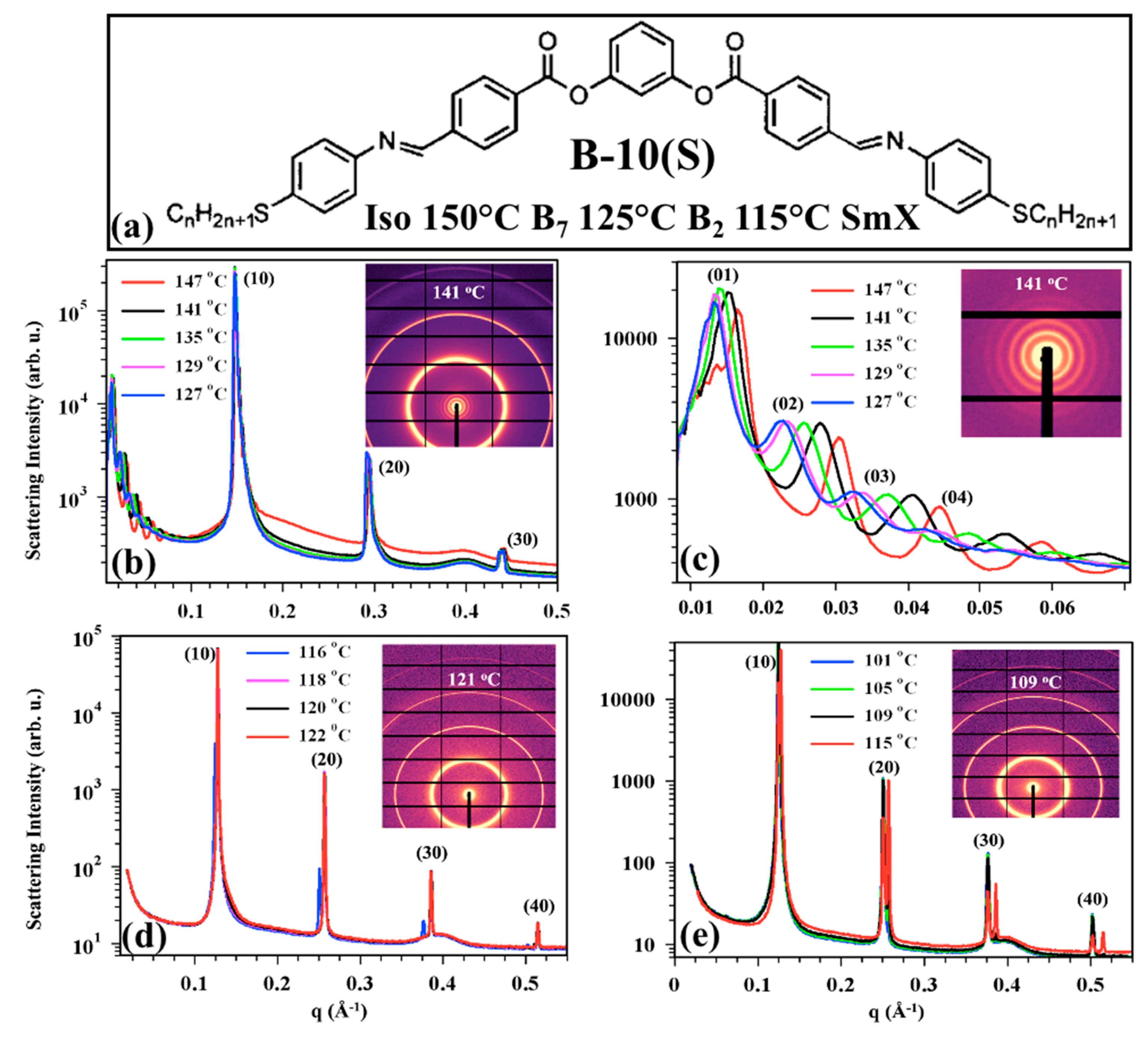
Figure 1. Molecular structure of B-10(S) and summary of small angle X-ray scattering (SAXS) results of B-10(S). (a) Molecular structure and observed phase sequence. (b,c) Scattering intensity versus q in the B7 texture in 0.01–0.5 Å−1 range (b) and 0.01–0.06 Å−1 range (c) at selected temperatures. Insets show the 2-D scattering image at 141 °C; (d) Scattering intensity versus q in the B2 phase in 0.01–0.5 Å−1 range at selected temperatures (inset: 2-D scattering image at 121 °C); (e) Scattering intensity versus q in the SmX phase in 0.01–0.5 Å−1 range at selected temperatures (inset: 2-D scattering image at 109 °C). The broad peak at 0.4 Å−1 is due to the Kapton tape used as a window in the SAXS measurements.
Crystals 10 00652 g001
Figure 2. Temperature dependence of the layer spacing, and correlation length of B-10(S), calculated from SAXS measurements. Shaded area between the B2 and SmX phases indicates phase overlap due to the first order nature of the transition. Inset shows the half periodicity of the layer undulation measured in the B7 phase.
Crystals 10 00652 g002
Figure 3. Main pane: Temperature dependence of switching electric threshold (where polarization peak appears). Inset shows the time dependences of electric current at 127 °C in the B7 phase (green) and at 118 °C in the B2 phase under Vpp = 160 V, f = 23 Hz triangular wave voltage (red). The error of the threshold field is ±0.2 V/µm.
Crystals 10 00652 g003
Figure 4. Temperature dependences of the slow (blue square and line) and fast (red squares and line) switching times corresponding to the positions of the slow (blue) and fast (red) peaks appear under rectangular voltages with ±84 V amplitudes, f = 20 kHz for detection of fast peak and f = 400 Hz for detection of slow peak, as shown in the insets. The errors are ±0.5 µs and ±0.02 ms for the fast and slow switching time measurements, respectively.
Crystals 10 00652 g004
Figure 5. Temperature dependence of the ferroelectric polarization, as calculated from the areas below the current peaks. Triangular symbols indicate the values measured under triangular wave voltages, and rectangular symbols correspond to data extracted from the measurements under rectangular voltage waveform. Open rectangles correspond to the areas of the slow (blue) and fast (red) peaks, while solid black rectangles are the sums of these two areas. The polarization values were determined with better than 10% precision.
Crystals 10 00652 g005
Figure 6. Representative POM textures of d = 4 µm B-10(S) film and their schematic director and layer structures of the circular area in the center of the image in the SmCPFmod phase at 127 °C. (a) While −80 V applied; (b) after the field is turned off; (c) when +80 V is applied.
Crystals 10 00652 g006
Figure 7. Representative POM textures of d = 4 µm B-10(S) film and their schematic director and layer structures of the circular area in the center of the image in the SmCPA phase at 118 °C. (a) Texture and schematics of the director and layer structure of the central circularly shaped domain after cooling at zero field from the isotropic phase; (b) texture and schematics of the director and layer structure of the central circularly shaped domain after driving with 12 V/µm, f = 12 Hz square wave field.
Crystals 10 00652 g007