Freedericksz Transitions in Twisted Ferronematics Subjected to Magnetic and Laser Field


Abstract
1. Introduction
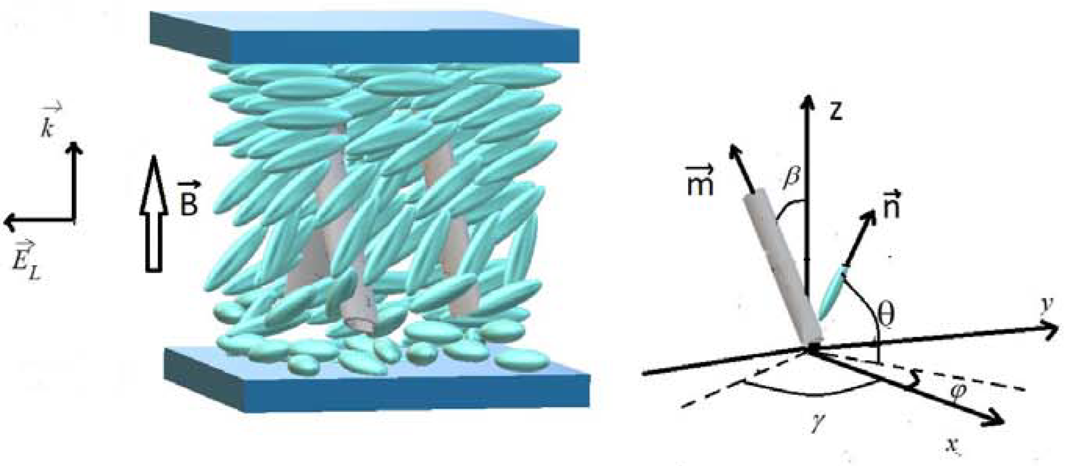
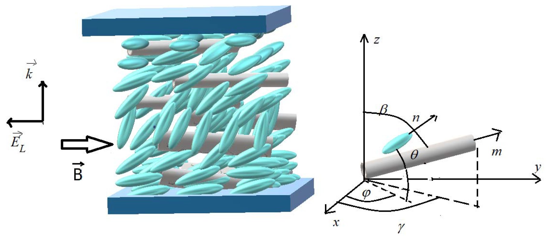
2. Theoretical Considerations
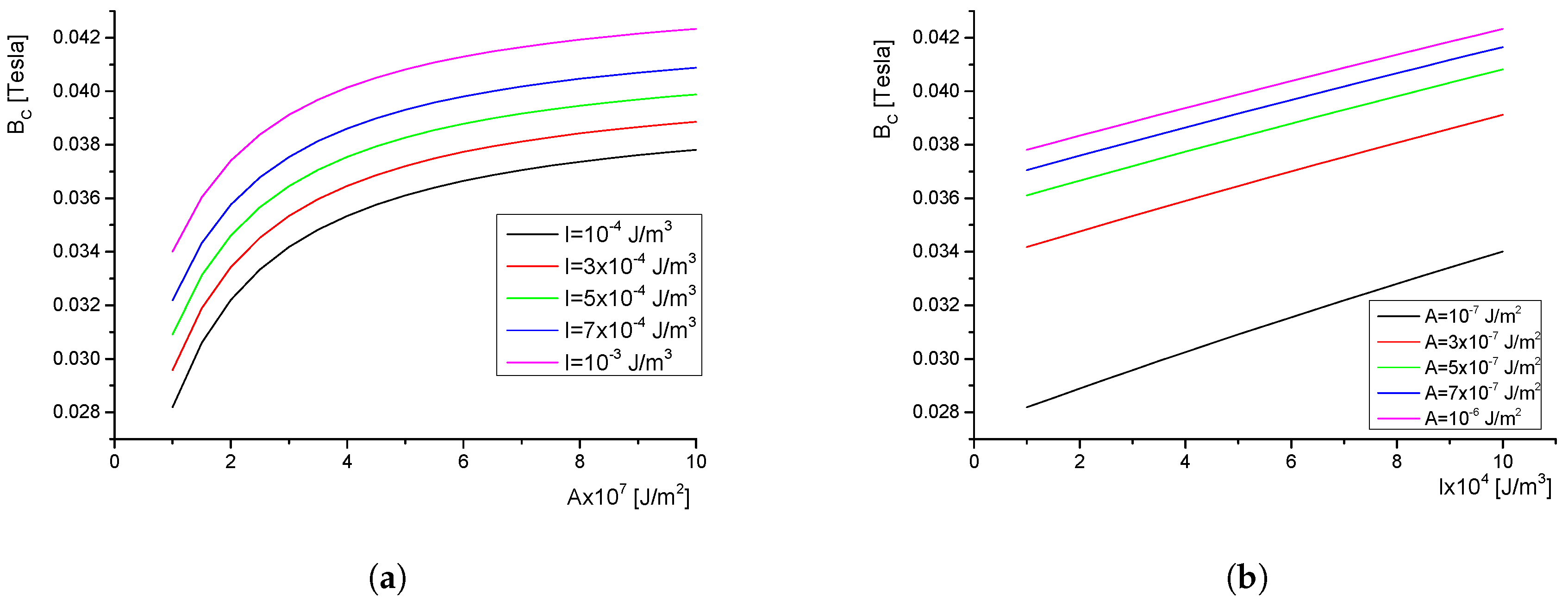
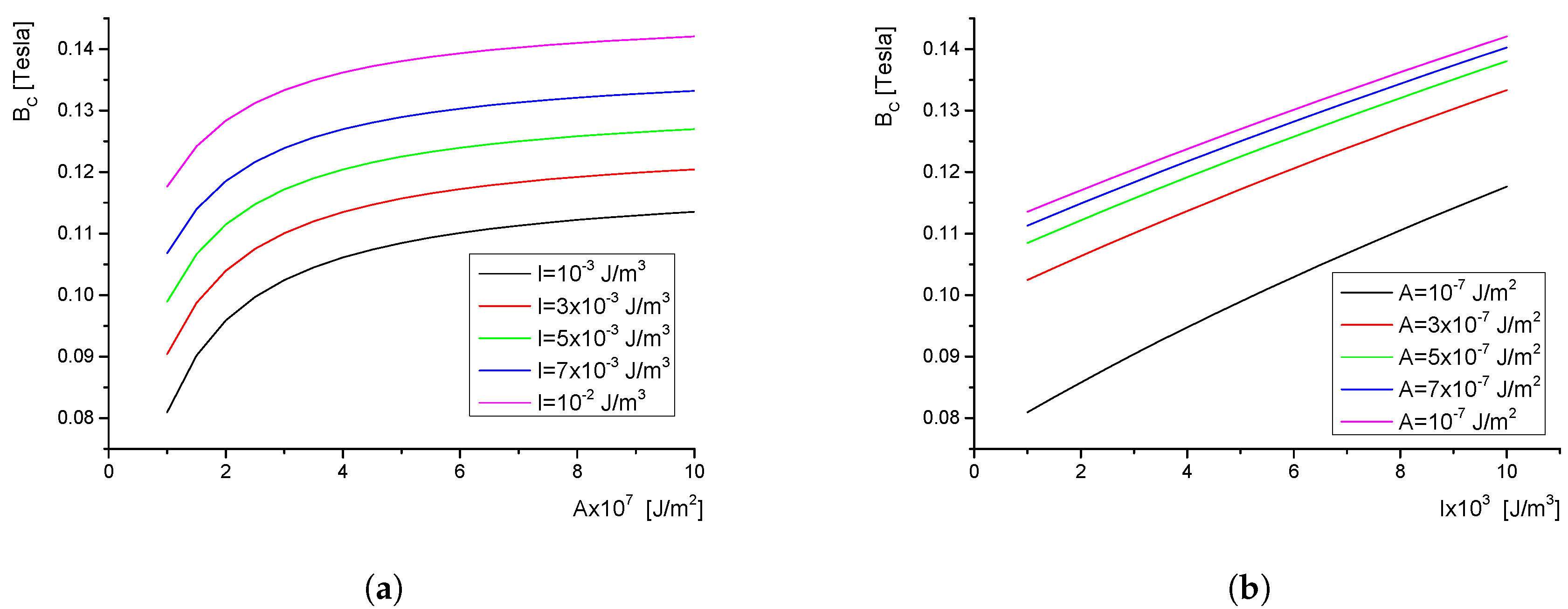
3. Critical Field
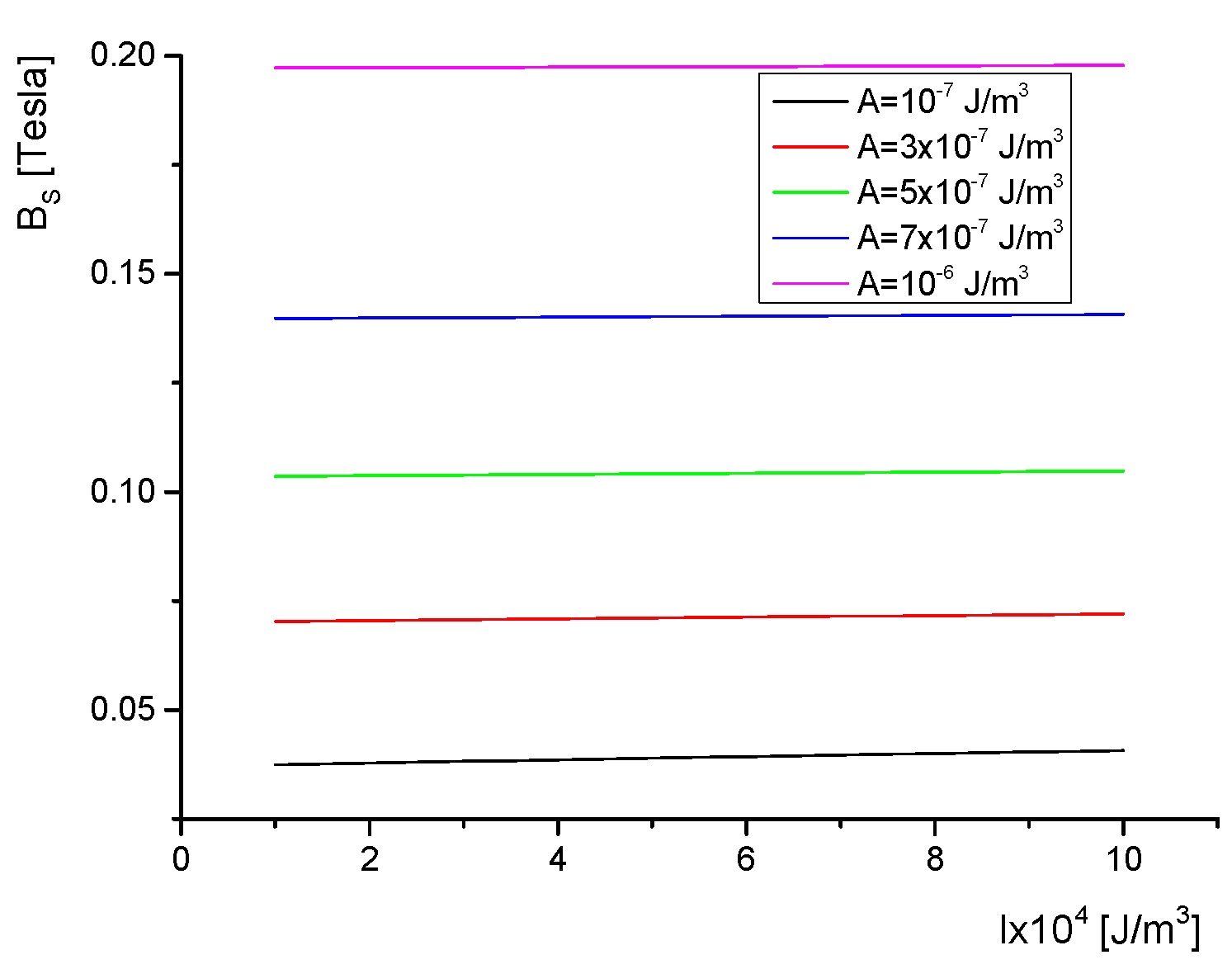
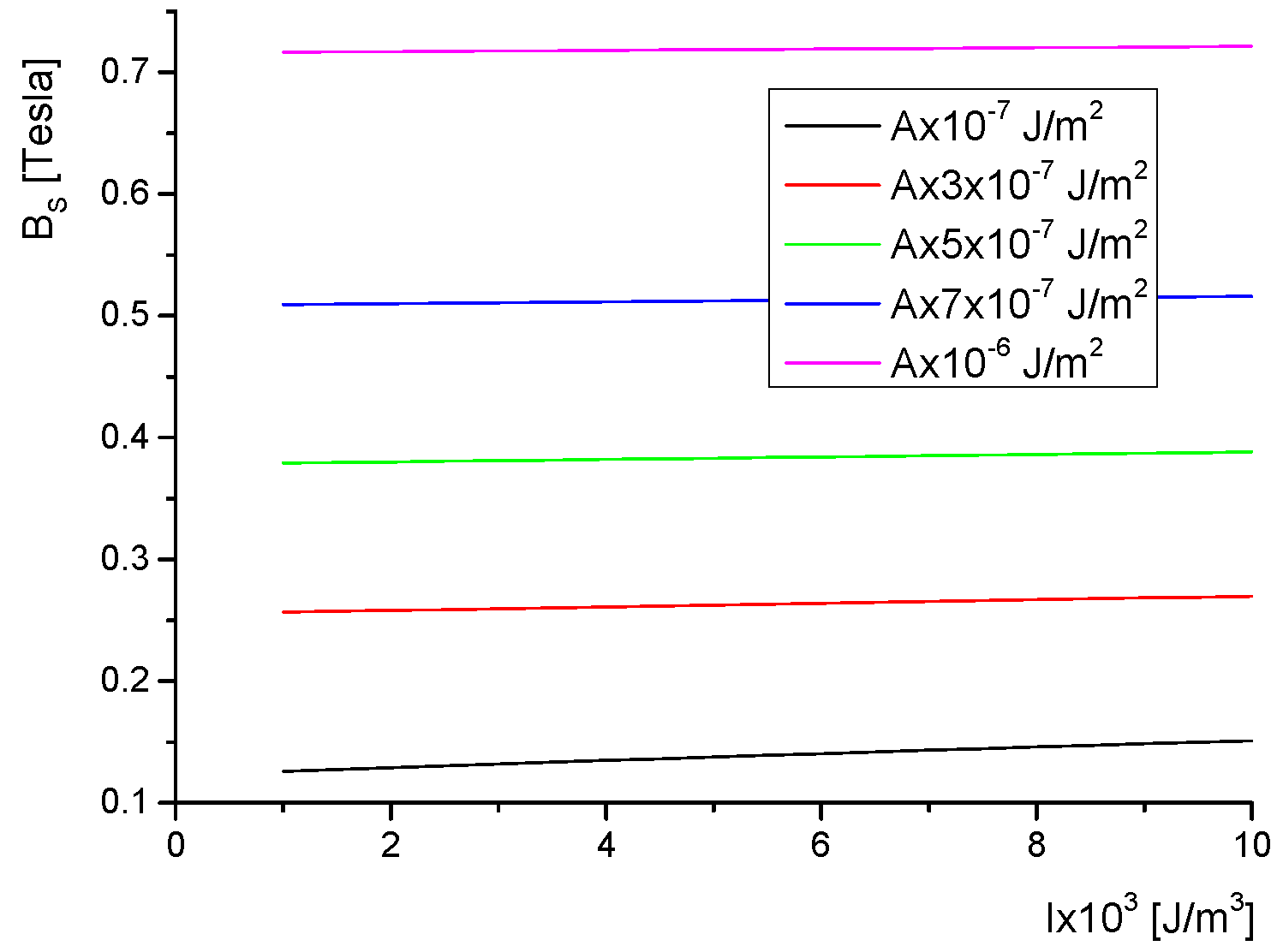
4. Saturation Field
5. Results and Discussions
6. Conclusions
Author Contributions
Funding
Acknowledgments
Conflicts of Interest
References
- Koch, K.; Kundt, M.; Eremin, A.; Nadasi, H.; Schmidt, A.M. Efficient ferronematic coupling with polymer-brush particles. Phys. Chem. Chem. Phys. 2020, 22, 2087–2097. [Google Scholar] [CrossRef] [PubMed]
- Romero-Hasler, P.; Martinez-Miranda, L.J.; Meneses-Franco, A.; Soto-Bustamante, E.A. TiO2 nanoparticle—liquid crystal interaction with smectogenic monomers and their electropolymerised polymers. Liq. Cryst. 2019. [Google Scholar] [CrossRef]
- Saravanan, M. Director deformation in a nematic liquid crystal with a ferromagnetic nanoparticle suspension. Chin. J. Phys. 2019, 59, 426–433. [Google Scholar] [CrossRef]
- Iabobescu, G.E. Freedericksz transitions of twisted ferronematics in magnetic field. J. Magn. Magn. Mater. 2018, 468, 65–68. [Google Scholar] [CrossRef]
- Saravanan, M.; Ameya, D.J.; Murthy, A.S.V. Perturbed soliton and director deformation in a ferronematic liquid crystal. Chaos Soliton Fract. 2018, 106, 220–226. [Google Scholar]
- Petrescu, E.; Cirtoaje, C. Dynamic behavior of a nematic liquid crystal mixed with CoFe2O4 ferromagnetic nanoparticles in a magnetic field. Beilstein J. Nanotech. 2017, 8, 2467–2473. [Google Scholar] [CrossRef]
- Bury, P.; Vevericik, M.; Kopcansky, P.; Timko, M.; Zavisova, V. Effect of spherical, rod-like and chain-like magnetic nanoparticles on magneto-optical response of nematics. Acta Phys. Pol. A 2019, 136, 101–106. [Google Scholar] [CrossRef]
- Petrescu, E.; Bena, E.R.; Citoaje, C. Polarization gratings using ferronematics-An elastic continuum theory. J. Magn. Magn. Mater. 2013, 336, 44–348. [Google Scholar] [CrossRef]
- Burylov, S.V.; Raikher, Y.L. Magnetic Fredericksz transition in a ferronematic. J. Magn. Magn. Mater. 1993, 122, 62–65. [Google Scholar] [CrossRef]
- Brochard, F.; De Gennes, P.G. Theory of magnetic suspensions in liquid crystals. J. Phys. France 1970, 31, 691–708. [Google Scholar] [CrossRef]
- Makarov, D.V.; Novikov, A.A.; Zakhlevnykh, A.N. Ferrocholesteric-ferronematic transitions induced by shear flow and magnetic field. Beilstein J. Nanotech. 2017, 8, 2552–2561. [Google Scholar] [CrossRef] [PubMed]
- Zakhlevnykh, A.N.; Petrov, D.A. Weak coupling effects and re-entrant transitions in ferronematic liquid crystals. J. Mol. Liq. 2014, 198, 223–233. [Google Scholar] [CrossRef]
- Burylov, S.V.; Raikher, Y.L. Orientation of a solid particle embedded in a monodomain nematic liquid-crystal. Phys. Rev. E 1994, 50, 358–367. [Google Scholar] [CrossRef] [PubMed]
- Cirtoaje, C.; Motoc, C.; Petrescu, E.; Bena, R.E. New magnetic methods for determination of elastic constants and rotational viscosity coefficient in nematic liquid crystals. Univer. Politeh. Buch. Ser. A 2010, 72, 233–246. [Google Scholar]
- Petrov, D.A.; Skokov, P.K.; Zakhlevnykh, A.N. Magnetic field induced orientational transitions in liquid crystals doped with carbon nanotubes. Beilstein J. Nanotech. 2017, 8, 2807–2817. [Google Scholar] [CrossRef]
- Jimenez-Marin, E.; Villalpando, I.; Trejo-Valdez, M.; Cervantes-Sodi, F.; Vargas-Garcia, J.R.; Torres-Torres, C. Coexistence of positive and negative photoconductivity in nickel oxide decorated multiwall carbon nanotubes. Mat. Sci. Eng. B Solid 2017, 1220, 22–29. [Google Scholar] [CrossRef]
- Chang, C.; Zhao, Y.; Liu, Y.; An, L. Liquid crystallinity of carbon nanotubes. RSC Adv. 2018, 8, 15780–15795. [Google Scholar] [CrossRef]
- Petrescu, E.; Cirtoaje, C. Dynamic behavior of a nematic liquid crystal with added carbon nanotubes in an electric field. Beilstein J. Nanotech. 2018, 9, 233–241. [Google Scholar] [CrossRef]
- Jain, A.K.; Deshmukh, R.R. Electro-optical and dielectric study of multi-walled carbon nanotube doped polymer dispersed liquid crystal films. Liq. Cryst. 2019, 8, 1191–1202. [Google Scholar] [CrossRef]
- Ara, M.H.M.; Dehghani, Z. Improvement of the third order nonlinear optical properties of nematic liquid crystal under the influence of different compositional percentage of doped SWCNT and the external electric field. J. Mol. Liq. 2019, 275, 281–289. [Google Scholar]
- Cetinkaya, M.C.; Yildiz, S.; Ozbek, H. The effect of -COOH functionalized carbon nanotube doping on electro-optical, thermo-optical and elastic properties of a highly polar smectic liquid crystal. J. Mol. Liq. 2018, 272, 801–2814. [Google Scholar] [CrossRef]
- Lisetski, L.N.; Fedoryako, A.P.; Samoilov, A.N.; Minenko, S.S.; Soskin, M.S.; Lebovka, N.I. Optical transmission of nematic liquid crystal 5CB doped by single-walled and multi-walled carbon nanotubes. Eur. J. Phys. 2014, 37, 68. [Google Scholar] [CrossRef] [PubMed]
- Atasiei, R.; Dascalu, C.; Raicopol, M. The time dependence of the electric charge in a nematic cell aligned with doped polypyrrole. Univer. Politeh. Buc. Ser. A 2013, 75, 293–298. [Google Scholar]
- Volpati, D.; Massey, M.K.; Johnson, D.W.; Kotsialos, A.; Qaiser, F.; Pearson, C.; Coleman, K.S.; Tiburzi, G.; Zeze, D.A.; Petty, M.C. Exploring the alignment of carbon nanotubes dispersed in a liquid crystal matrix using coplanar electrodes. J. Appl. Phys. 2015, 117, 125303. [Google Scholar] [CrossRef]
- Denktas, C.; Ocak, H.; Okutan, M.; Yildiz, A.; Eran, B.B.; Koysal, O. Effect of multi wall carbon nanotube on electrical properties 4-[4-((S)-Citronellyloxy)benzoyloxy]benzoic acid liquid crystal host. Compos. Part B Eng. 2015, 82, 173–177. [Google Scholar] [CrossRef]
- Bale, S.; Liyana-Arachchi, T.P.; Hung, F.R. Molecular dynamics simulation of single-walled carbon nanotubes inside liquid crystals. Mol. Simulat. 2016, 42, 1242–1248. [Google Scholar] [CrossRef]
- Yadav, S.P.; Singh, S. Carbon nanotube dispersion in nematic liquid crystals: An overview. Prog. Mater. Sci. 2016, 80, 38–176. [Google Scholar] [CrossRef]
- Kedzierski, K.; Rytel, K.; Barszcz, B.; Gronostaj, A.; Majchrzycki, L.; Wrobel, D. On the temperature dependent electrical resistivity of CNT layers in view of Variable Range Hopping models. Org. Electron. 2017, 43, 253–261. [Google Scholar] [CrossRef]
- Palarie, I.; Dascalu, C.; Iacobescu, G.E. Controlling the orientation of microgrooves and the depth of the ripple structure in dye-doped liquid crystal cells. Liq. Cryst. 2010, 37, 195–199. [Google Scholar] [CrossRef]
- Staic, M.; Petrescu-Nita, A. Symmetry group of two special types of carbon nanotori. Acta Crystallogr. 2013, 69, 435–439. [Google Scholar] [CrossRef]
- Assanto, G.; Alberucci, A.; Piccardi, A. Nematicons. In Nematicons: Spatial Optical Solitons in Nematic Liquid Crystals; Assanto, G., Ed.; Wiley: Hoboken, NJ, USA, 2012. [Google Scholar]
- Ian Stewart, W. The Static and Dinamic Continuum Theory of Liquid Crystals a Mathematical Introduction; Taylor & Francis: London, UK; New York, NY, USA, 2004; p. 330. [Google Scholar]
- Rapini, A.; Papoular, M. Distorsion d’une lamelle nématique sous champ magnétique conditions d’ancrage aux parois. J. Phys. Colloques 1969, 30, C4-54–C4-56. [Google Scholar] [CrossRef]
- Guochen, Y.; Jianru, S.; Ying, L. Surface anchoring energy and the first order Freedericksz transition of a NLC cell. Liq. Cryst. 2000, 27, 875–882. [Google Scholar] [CrossRef]
- Oswald, P.; Pieranski, P. Nematic and Cholesteric Liquid Crystals; Taylor & Francis Group: Oxfordshire, UK, 2005; pp. 157–158. [Google Scholar]
- Cirtoaje, C.; Petrescu, E.; Stan, C.; Creanga, D. Ferromagnetic nanoparticles suspensions in twisted nematic. Physica E 2016, 79, 38–43. [Google Scholar] [CrossRef]
- Oswald, P.; Poy, G.; Dequidt, A. Lehmann rotation of twisted bipolar cholesteric droplets: Role of Leslie, Akopyan and Zel’dovich thermomechanical coupling terms of nematodynamics. Liq. Cryst. 2016, 44, 969–988. [Google Scholar] [CrossRef]


© 2020 by the authors. Licensee MDPI, Basel, Switzerland. This article is an open access article distributed under the terms and conditions of the Creative Commons Attribution (CC BY) license (http://creativecommons.org/licenses/by/4.0/).
Share and Cite
Cirtoaje, C.; Iacobescu, G.; Petrescu, E. Freedericksz Transitions in Twisted Ferronematics Subjected to Magnetic and Laser Field. Crystals 2020, 10, 567. https://doi.org/10.3390/cryst10070567
Cirtoaje C, Iacobescu G, Petrescu E. Freedericksz Transitions in Twisted Ferronematics Subjected to Magnetic and Laser Field. Crystals. 2020; 10(7):567. https://doi.org/10.3390/cryst10070567
Chicago/Turabian StyleCirtoaje, Cristina, Gabriela Iacobescu, and Emil Petrescu. 2020. "Freedericksz Transitions in Twisted Ferronematics Subjected to Magnetic and Laser Field" Crystals 10, no. 7: 567. https://doi.org/10.3390/cryst10070567
APA StyleCirtoaje, C., Iacobescu, G., & Petrescu, E. (2020). Freedericksz Transitions in Twisted Ferronematics Subjected to Magnetic and Laser Field. Crystals, 10(7), 567. https://doi.org/10.3390/cryst10070567