Article

Structural Refinement and Density Functional Theory Study of Synthetic Ge-Akaganéite (β-FeOOH)

1
Department of Earth System Sciences, Yonsei University, Seodaemun-gu, Yonsei-ro 50, Seoul 03722, Korea
2
Korea Institute of Geoscience and Mineral Resources, 124 Gwahang-ro, Daejeon 305350, Korea
*
Author to whom correspondence should be addressed.
Crystals 2020, 10(4), 239; https://doi.org/10.3390/cryst10040239
Submission received: 14 February 2020 / Revised: 20 March 2020 / Accepted: 23 March 2020 / Published: 25 March 2020

Abstract

:
In this study, we propose a revised structural model for highly ordered synthetic Ge-akaganéite, a stable analogue of tunnel-type Fe-oxyhydroxide, based on the Rietveld refinement of synchrotron X-ray diffraction data and density functional theory with dispersion correction (DFT-D) calculations. In the proposed crystal structure of Ge-akaganéite, Ge is found not only in the tunnel sites as GeO(OH)3 tetrahedra, but also 4/5 of total Ge atoms are in the octahedral sites substituting 1/10 of Fe. In addition, the tunnel structures are stabilized by the presence of hydrogen bonds between the framework OH and Cl species, forming a twisted cube structure and the GeO(OH)3 tetrahedra corner oxygen, forming a conjugation bond. The chemical formula of the synthetic Ge-akaganéite was determined to be (Fe7.2Ge0.8)O8.8(OH)7.2Cl0.8(Ge(OH)4)0.2.

1. Introduction

Akaganéite is a major Fe-oxide component in high chloride environments [1,2]. More specifically, it is a naturally occurring polymorph of the ferric oxyhydroxides (β-FeOOH) and is composed of FeO3(OH)3 octahedra that form a hollandite-like tunnel-type structure along the [010] plane, which is partially occupied by Cl ions [3,4]. These Cl ions play an important role in stabilizing the tunnel structure through the formation of hydrogen bonds [3,4,5]. To compensate for the charge of the Cl ions, an equal quantity of H+ ions is required, and these H+ ions form hydroxyl (OH) ions upon combination with oxygen. This gives a chemical formula of FeO1−x(OH)1+xClx for the akaganéite structure. Both natural and synthetic akaganéite rarely occur as single crystals, with a tendency of spindle-shaped crystallites ranging from 0.1 to 1.0 µm in size to form. Because of the sorption ability of the tunnel structures, akaganéite has recently attracted considerable research interest for the preparation of uniform nanocrystalline hematite (α-Fe2O3) particles [6,7,8], and for the environmental remediation of aqueous phosphate [9] and arsenic [10]. In addition, akaganéite is advantageous as a dopant for battery anodes and cathodes due to its high surface area and porous morphology [11,12]. However, as akaganéite is poorly crystalline and metastable under ambient conditions and easily transformed to the more stable hematite form through dehydration or dihydroxylation [7,13,14,15], its applicability is severely restricted. To address such issues, the highly ordered Ge-akaganéite, exhibiting a crystalline structure composed of rod-shaped particles measuring ~2.0 µm in length, was synthesized by the hydrolysis of FeCl3·6H2O and TEOGe (tetra-ethyl-orthogermanate; Ge(OC2H5)4) under acidic to alkaline conditions. In addition, Song et al. (2011) suggested the structural model for Ge-akaganéite of FeO0.9(OH)1.1Cl0.1(Ge(OH)4)0.137 based on thermogravimetric-differential thermal analysis (TG-DTA) and transmission electron microscopy coupled with energy-dispersive X-ray spectroscopy (TEM-EDX), in which the Ge atoms were found only in the tunnel sites as Ge(OH)4 tetrahedra [16]. Despite the enhanced crystallinity and stability of Ge-akaganéite, its accurate structural refinement has not been performed as no crystallographic details have been supplied, and the Ge sites remain questionable. Thus, we herein attempt to define the crystal structure of highly ordered Ge-akaganéite using the Rietveld refinement of synchrotron X-ray diffraction data and a computational method based on the density functional theory with dispersion correction (DFT-D) approach to propose a revised structural model for Ge-akaganéite. In particular, we investigate the geometry of the tunnel tetrahedral Ge(OH)4 and the influence of hydrogen atoms on the structure using a theoretical approach.

2. Materials and Methods

2.1. Experimental Synthesis and Characterization

The synthesis of Ge-akaganéite begins by adding tetraethylorthogermanate (TEOGe, Ge(OC2H5)4) dropwise into 2 mM of FeCl3·6H2O solution until the molar ratio of Fe/Ge reached 2, at which point, the solution was stirred vigorously for 30 min. A 1M NaOH solution was added at the rate of 0.5 mL/min under stirring until the pH of the solution reached 13. The pH of the solution is brought down immediately to 1.5 by dropwise addition of 12M HCl. The resulting solution gradually became light yellow in colour and was then stirred for 1 h at room temperature. The suspension is then aged in the oven for 5 days at 95 °C. The solution is flocculated by adding several drops of ammonia water and centrifuged. In the last step, the flocculant was washed with deionized water and ethanol, then dialyzed against deionized water for 3 days. The atomic ratios of the Ge-akaganéite were determined as Ge/Fe = 0.14 and Cl/Fe = 0.11, with a weight loss of 16.4% and paramagnetic properties as obtained by TEM-EDX (JEOL JEM-2200FS transmission electron microscope operated at 200 kV, Tokyo, Japan), TG-DTA (Thermogravimetric differential thermal analysis data were collected in the range of 25–1000 °C with the rate increasing by 10 °C min−1 using TG-DTA 2000S, MAC science, Japan). and zero-field-cooled susceptibility curves, respectively [16]. The extended X-ray absorption fine structure (EXAFS) measurement was performed at the 7C1 beamline of the Pohang Accelerator Laboratory (PAL) in Pohang, Korea (Figure S2 and Table S1 (see Supplementary Materials)).

2.2. X-Ray Diffraction and Rietveld Refinement

The refinement details and conditions employed herein are summarized in Table S1 and Figure S1. Synchrotron X-ray diffraction for the Ge-akageneite was performed at the 8C2 beamline of the PAL. The diffraction pattern was collected using an X-ray beam with λ = 1.5489(1) Å in the range from 8° to 128.5° (2θ) at a step of 0.02° and a measurement time of 18 s per step. The unit cell parameters of Ge-akaganéite were previously determined by Le Bail fitting in the general structure and analysis system (GSAS) (Los Alamos National Laboratory, New Mexico, USA) [17,18] and starting with the structural model of natural akageneite [3]. From the reported synchrotron X-ray diffraction data [16], background subtraction was performed using a Chebyshev polynomial, and a peak shape simulation was performed employing the pseudo-Voigt function. Framework elements were fixed as fully occupied, and the same elements shared isotropic temperature factors (Uiso). Following the imposition of the framework elements on the structural model, a difference Fourier (difference electron Fourier, DELF) calculation was performed to search for possible Ge locations. The atomic ratios of the Ge-akaganéite components were fixed as Ge/Fe = 0.14 and Cl/Fe = 0.11, as determined by TEM-EDX [16]. Placing the Ge-tetrahedra in the tunnel site broke the symmetry (I 2/m) of natural akaganéite to give the body-centered unit cell (I). To maintain the space group symmetry of akaganéite, the tunnel Ge-tetrahedra were assumed to be Gd in the refinement upon consideration of the electron number of these Ge-tetrahedra, and the positions of the tunnel elements were assumed to be identical. The bond lengths were constrained using the Shannon radii distance [19] i.e., 2.02 and 2.84 Å for Fe–O and O–O, with estimated errors of 0.02 and 0.05, respectively. [CCDC 1842418 contains the supplementary crystallographic data for this paper. These data can be obtained free of charge via http://www.ccdc.cam.ac.uk/conts/retrieving.html (or from the CCDC, 12 Union Road, Cambridge CB2 1EZ, UK; Fax: +44-1223-336033; E-mail: [email protected])].

2.3. Computational Approach

DFT-D calculations were performed using the Cambridge Sequential Total Energy Package (CASTEP) [20,21] code of the Material Studio program. All calculations have been performed based on spin-unrestricted calculation [22,23]. Geometrical optimization was performed using the generalized gradient approximation (GGA) with the Perdew–Burke–Ernzerhof (PBE) [24] function to calculate the ground state enthalpy and to obtain the tunnel structure [25,26,27]. For van der Waals dispersion correction, the semi-empirical approach from Tkatchenko–Scheffler (TS) [28] was adopted. Upon pseudo atomic calculation, oxygen, chlorine, iron and germanium had six (2s2 2p4), seven (3s2 3p5), eight (3d7 4s1) and fourteen (3d10 4s2 4p2) valence electrons, respectively. The convergence tolerances of optimization were 2.0 × 10⁻⁵ eV/atom, 0.05 eV/Å, 0.1 GPa, and 0.002 Å for the energy, max. force, stress, and displacement, respectively. We selected the Broyden–Fletcher–Goldfarb–Shanno (BFGS) algorithm [29] for minimization. The self-consistent field (SCF) tolerance of 2.0 × 10⁻⁶ eV/atom was applied. The energy cutoff of wavefunctions were applied 571.4 eV (21 Hatree). To calculate the total energies and density of states (DOS) of the final model, k point mesh of Brillouin zone 3 × 2 × 3 and 7 × 5 × 7 were applied for each, which were generated by Monkhorst–Pack grid [30]. Energy cutoff and Monkhorst–Pack grid were selected by less differences (total energy differences less than 0.1 eV) from the coarser conditions.
In order to obtain the tunnel structure, cell parameters and framework atom positions (Fe1, Fe2, O1 to O4 in the refinement) were constrained as the refinement result. To compare the models of different tunnel Ge occupancies, DFT-D calculations were performed for the models with different Ge distributions between the octahedral and tunnel sites to verify the refined model. In the calculation, we used the same supercell (1 × 5 × 1) with the refined structure. Five models with different numbers for the Ge-tetrahedra in the tunnel sites were compared using energy and distances between atoms.

3. Results and Discussion

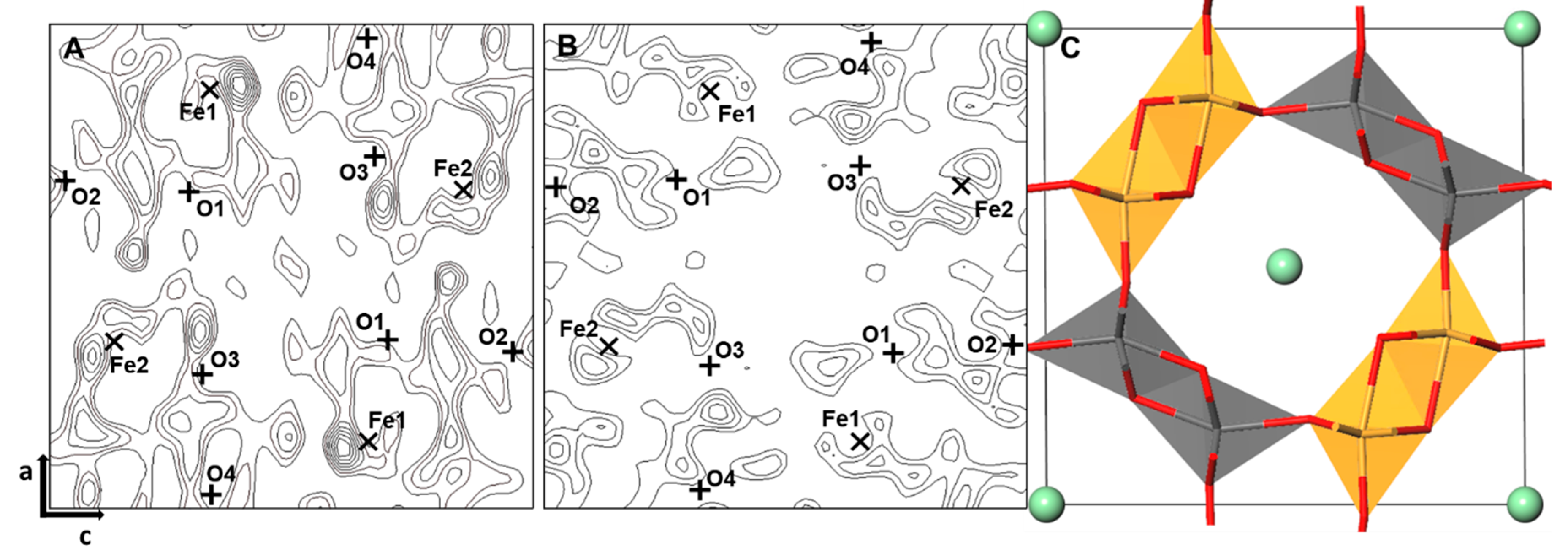
3.1. Finding the Ge Sites Using DELF Contour Map Analysis

As the initial step of the Rietveld refinement, we attempted to determine possible sites for the Ge atoms within the akaganéite structure using DELF contour map analysis, which shows the differences in electron density resulting from atoms within a crystal structure and can be calculated from X-ray diffraction data. Initially, we calculated the DELF contour map for the Fe-occupied octahedral framework of akaganéite at y = 0, and significant differences were observed at the Fe1 site in addition to smaller differences at the Fe2, O3, and tunnel sites (Figure 1A). The differences in electron density can be minimized by positioning a cation with a higher atomic number than Fe, such as Ge, and so we considered that the octahedral Fe1 site could also be a possible site for Ge. Moreover, with consideration of suggested model structure from previous study [16] and other hollandite structure studies [25,26,27], we performed Rietveld refinement for the model with three possible Ge sites as follows: (1) Ge is found only at the Fe1 sites, (2) Ge is found at both the Fe1 and tunnel sites, and (3) Ge is found only at the tunnel sites, as proposed by Song et al. (2011). The refinement results show that, convergence was only achieved in the case of (2), and the corresponding DELF map shows a distinct reduction in the differences at the Fe1 site (Figure 1B). Therefore, we proposed a new structural model for Ge-akaganéite where Ge is present both in octahedral Fe1 and tunnel sites (Figure 1C).

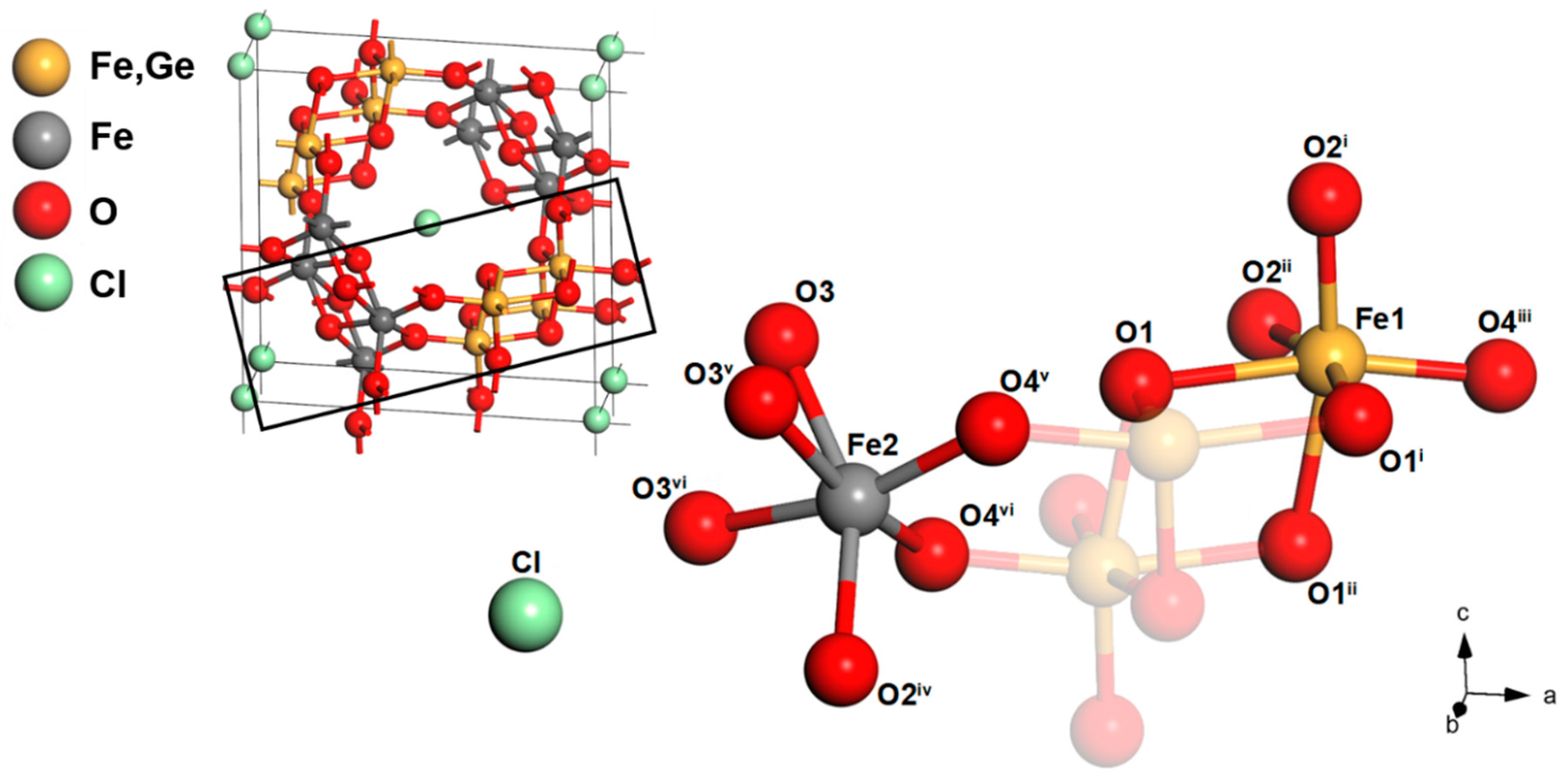
3.2. Structure of Ge-Akaganéite

The refinement parameters and atomic coordinates with the isotropic displacement factors for the newly proposed Ge-akaganéite model are presented in Table 1. The volume of Ge-akaganéite is V = 330.99 (5) Å3, which is smaller than that of natural akaganéite (V = 338.13 (2) Å3), and corresponds with the suggested unit cell parameters of a = 10.50 Å and b = 3.02 Å, as measured directly from HRTEM images [16]. Weighted residual factor and chi square of refinement were Rwp = 0.068 and χ2 (chi square) = 2.890, which represent goodness of fit. The presence of Ge can be expressed as 1/5 of Ge(OH)4 at the tunnel sites with an occupancy level of 0.05, and 4/5 of Ge at the Fe1 sites with occupancy levels of 0.2. The structural formula of the refined model can therefore be expressed as (Fe7.2Ge0.8)O8.8(OH)7.2Cl0.8(Ge(OH)4)0.2 with chemical compensation. The refined octahedral framework shows distinct distortion in the Fe1 and Fe2 site (Figure 2, Table 2), in which the angles of O–Fe–O in the FeO3(OH)3 octahedron (153 to 166°) are significantly twisted (Table 2). This octahedral distortion is a common phenomenon in this particular spin-polarized system originated from d-orbital t2g energy differentiation of dxy (angular distortion in both Fe1 and Fe2), known as Jahn–Teller distortion [31,32,33] as described from other hollandite structures [25,26,27]. The extended X-ray absorption fine structure (EXAFS) study of the Ge local structures indicates a coordination number close to five (Figure S2 and Table S2), which may be explained by the severe distortion of the octahedral Fe1 (Fe, Ge) site.

3.3. Model Verification Using the Enthalpy of Formation

We performed CASTEP calculations for the models with different Ge distributions between the octahedral and tunnel sites to verify the refined model. The structural framework of the newly proposed model (Figure 1C) was then applied as the base set to optimize the tunnel structure. We constructed a 1 × 5 × 1 supercell of Ge-akaganéite with full occupancy of each element in the octahedral and tunnel sites. The hydrogen atoms were attached at the O1 and O3 sites of the octahedral framework as per the natural akaganéite structure [4] (Figure 3), and the refined positions of the framework atoms were fixed. The elements in the tunnel sites, including hydrogen atoms, were optimized through DFT-D calculations. The general formula of the supercell was as follows:
( Fe 35 + N Ge 5 N ) O 41 N ( OH ) 39 + N Cl 4 { Ge ( OH ) 4 } N
In the calculation, five models with different N values for the Ge-tetrahedra (Equation (1)) in the tunnel sites, between 0 and 4 were labelled I to V respectively (Table 3). The N value was restricted to a maximum of 4 due to the steric hindrance between the Cl atoms and the Ge-tetrahedra in the tunnel sites, in which more than five Ge-tetrahedra cannot be assigned geometrically. Model II corresponds to the newly proposed Ge-akaganéite. From the calculation results, we could compare the formation enthalpies (∆H) of the five crystal models. As the calculated enthalpies for optimized models have been previously used to compare the relative stabilities of some materials [34,35]. We therefore determined the formation enthalpies of the five models by subtracting the component energies as follows:
Formation   Δ H   of   akagan é ite =   total   Δ H   of   akagan é ite Δ H   of   elements
In the enthalpy calculation, the optimized energies of the elements in the structure were used (Table S3). The calculated results for the formation enthalpies of the five models are presented in Table 3. It is found that model II (N = 1), i.e., the newly proposed model with a chemical formula of (Fe7.2Ge0.8)O8.8(OH)7.2Cl0.8(Ge(OH)4)0.2, is the most stable phase. Thus, the calculated enthalpies with respect to the lowest energy case (i.e., model II) are 10.382, 0.021, 5.551 and 81.927 kcal/mol for models I, III, IV, and V, respectively (Figure S3, Table 3). The large increase in the enthalpy difference for model V indicates that the presence of four Ge-tetrahedra in the tunnel site renders the structure significantly less stable. Similarly, the differences in stability among the models could be explained by comparison of the distances between the tunnel atoms. Generally, the hydrogen bond energy of HO–H–OH was reported as 27.8 kcal/mol [36], thereby indicating that the formation of hydrogen bonds can cause significant differences in the formation enthalpies of structures. As the studies on natural akaganéite had already suggested, the tunnel Cl anions and eight H atoms form a twisted prism to stabilize the structure [3,4]. However, despite the increase of H atoms in the tunnel site, the number of hydrogen bonds between Cl and H were unchanged. So, when investigating the Ge-tetrahedra, the hydrogen bond increased the stability between each Ge-tetrahedra and framework OH. Moreover, the optimized models show that the structures of two or more Ge-tetrahedra in the tunnel site result in a repulsive distance (Cl–O), which renders the structure unstable (Figure S5, Table 3).

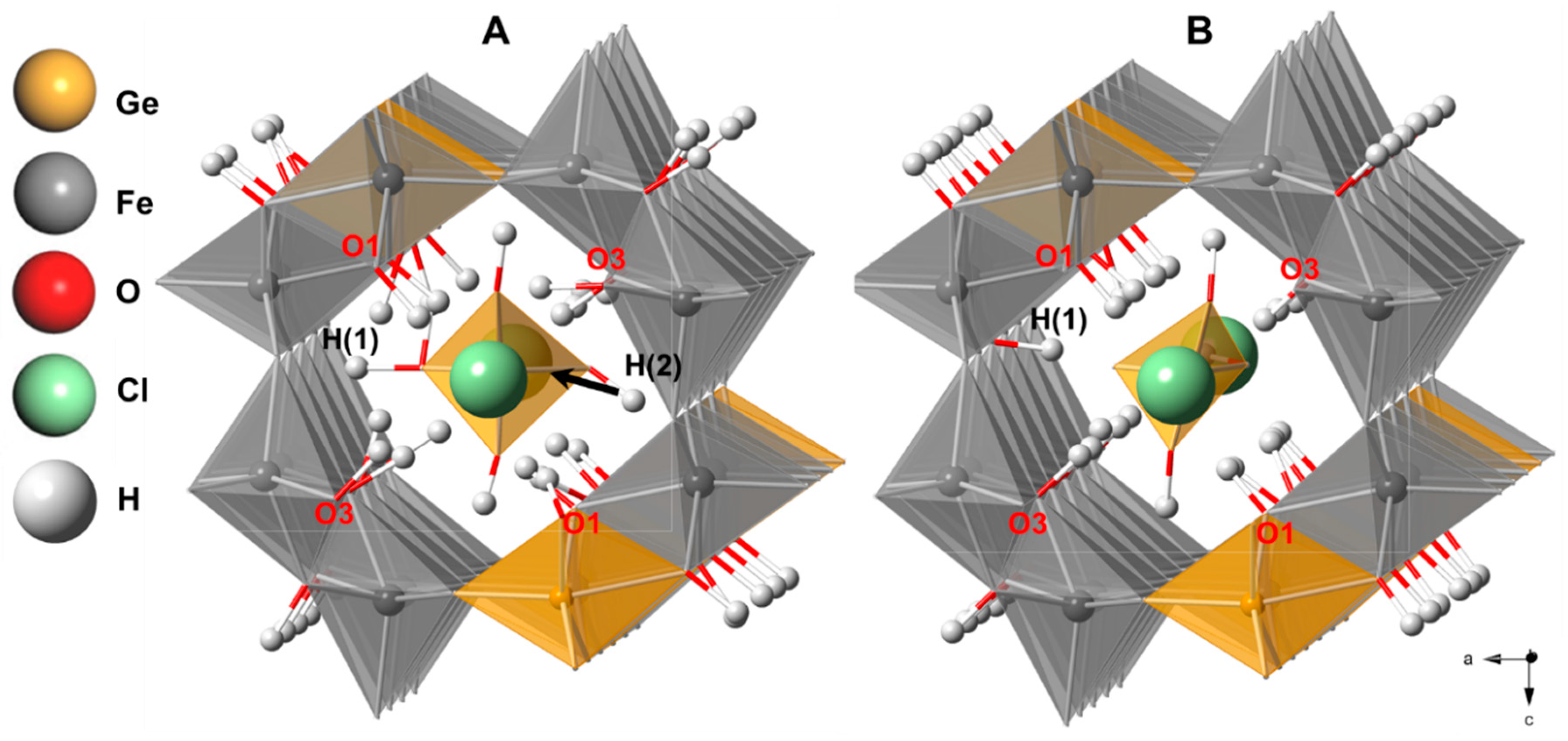
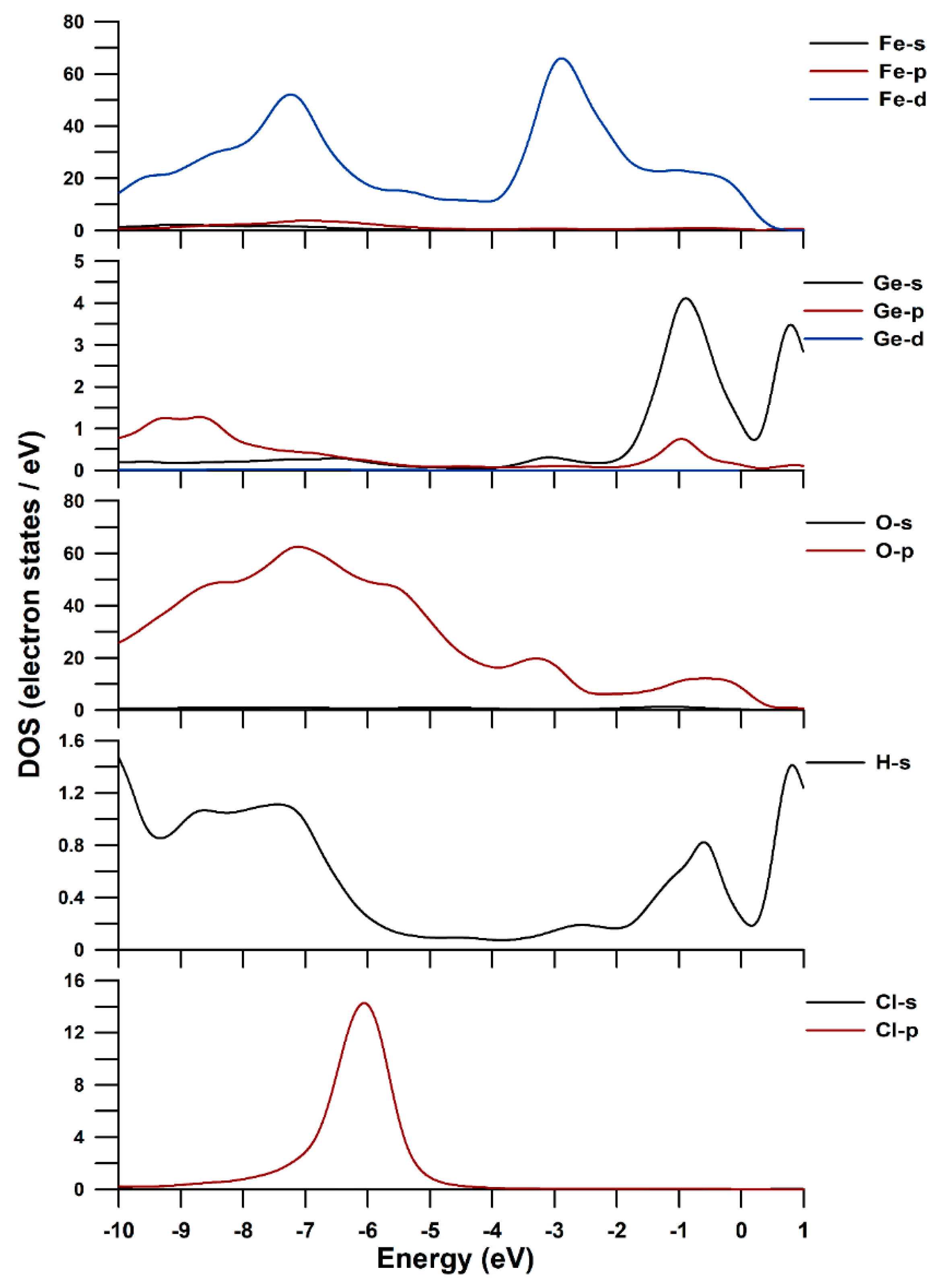
3.4. DFT-D Calculation and DOS of Ge-Akaganéite

The model formula was the same as that suggested in the structural refinement ((Fe7.2Ge0.8)O8.8(OH)7.2Cl0.8(Ge(OH)4)0.2) and model II. We applied k point meshes which were generated by the Monkhorst–Pack grid [30] of Brillouin zones 3 × 2 × 3 and 7 × 5 × 7, respectively. The elements in the tunnel sites, including hydrogen atoms attached to the framework, were optimized through DFT-D calculations, and the geometries after optimization are presented in Figure 3 and Table 4. In the optimized model structure, the Ge(OH)4 tetrahedra in the tunnel site differ significantly. More specifically, in the optimized structure, the H(1) of the tetrahedron is found at a distance of 1.083 Å from O2, which means that it would be bound to the O2 of the octahedron, rather than to the corner oxygen (O(T3)) of the tetrahedron, thereby indicating that the negative charge of GeO(OH)3 is preferentially positioned in the tunnel site (Figure 3B, Table 4). In the Ge-tetrahedron, the oxygen and hydrogen atoms also form hydrogen bonds with the framework oxygen and hydrogen atoms (Table S3). More specifically, there are three hydrogen atoms in each tetrahedron, which form strong hydrogen bonds with the O2 and O4 atoms of the framework. The eight hydrogen atoms of the framework OH groups (O1 and O3) also participate in hydrogen bonding with the corner oxygen atoms of the tunnel tetrahedra (Figure 4, Table 4, Table S3). In addition, Cl anions in the other tunnel sites form hydrogen bonds with the H atoms attached to O1 and O3 (Figure 5, Figures S4 and S5, Table S3). The Cl anions in the tunnel site are hydrogen bonded eight-fold to H atoms and are located at the center of a twisted cube with Cl–H distances ranging from 1.85 to 2.79 Å (Figure 5, Table S4). The detailed coordinates of the atoms in the optimized Ge-akaganéite structure are summarized in Table S4.
In the structure of the optimized model, the tunnel Cl anions are stabilized by H atoms attached to O1 and O3 (Figure 3B, Figure 5, Figures S4 and S5, Table S3), which form hydrogen bonds between Cl and H [37]. As the tunnel Cl anions in the natural akaganéite form a prism with eight H atoms to stabilize the structure [3,4], we could surmise that the Cl–H twisted cubic structure in Ge-akaganéite also stabilizes the structure (Table S3). In the case of the Ge-tetrahedra, as in the case of the Cl atoms present in the tunnel sites, the oxygen and hydrogen atoms form short hydrogen bonds with the framework oxygen and hydrogen atoms (Table 4). These short hydrogen bond distances indicate strong conjugated bonds [38,39,40].
Figure 6 illustrates the partial density of states (PDOS), which is the electron states of Fe(3d,4s,4p), Ge(3d,4s,4p), O(2s,2p), H(1s), and Cl(3s,3p), respectively. The PDOS range that we show is known as the bonding energy range (−10 eV to 0 eV from the Fermi level). In PDOS, the 3d orbital of iron, 4s and 4p orbitals of germanium, 2p orbital of oxygen, and 3p orbital of chlorine are shown to be the main orbitals that participate in the bonding. It can be seen that the 2p orbitals of oxygen have overlapped with 3d orbitals of iron and 4s and 4p orbitals of germanium within the region of −10 to 0 eV. As we mentioned in the structural analysis, the Fe d-orbital, which provides a major contribution to the bonding, is thought to be the reason for the distortion of the octahedron [31,32]. The 2p orbitals of oxygen and 1s orbitals of hydrogen also overlap in −10 to 0 eV, showing a strong bond strength, which may indicate the existence of a strong hydrogen bond in the structure as we mentioned previously (Figure 4 and Table 4). Because of the known limitation of the non-metallic material calculation (magnetic moments, underestimated band gap, etc.) [41,42], the direct interpretation of these calculated results is risky. Not just because of the unrealistic parameter results (typically OH bond strength in water is known as about 4.8 eV), but of the assumptions made from calculation. Generally the tendency of the ‘overbinding’ between the OH–O interactions was reported in the condition of PBE-Grimme method [43,44] which is well-known dispersion correction. Therefore, considering the existence of the hydrogen bond in this structure, the semi-empirical van der Waals correction method (TS) have been adopted for this study [28] to reduce the ‘overbinding’ problem [45]. However, there is still a tendency to overestimate hydrogen bonding (overlapped orbitals of hydrogen and oxygen are distributed around −10 to −6 eV). Therefore, in this calculation, PDOS only be used as a relative comparison of orbitals which take part in bond.

4. Conclusions

We herein defined the crystal structure of Ge-akaganéite obtained by the Rietveld refinement of synchrotron X-ray diffraction data and DFT-D calculations. From DELF map analysis, we found that both the Fe1 octahedral and tunnel sites were possible sites for the incorporation of Ge. Indeed, we proposed a new structural model for Ge-akaganéite, where 4/5 of the total Ge atoms are in octahedral Fe1 sites and 1/5 of the total Ge atoms are in tunnel sites. Through the Rietveld refinement, the structural model was optimized using DFT-D calculations, and analysis of the enthalpies of the model structures indicates that the stability of the Ge-akaganéite model is significantly influenced by the formation of hydrogen bonds and by repulsive distances within the tunnel. Furthermore, the distances between hydrogen atoms and the corner oxygen atoms in the tunnel tetrahedra suggest that the tunnel Ge(OH)4 tetrahedra may preferentially adopt the GeO(OH)3 form. Consequently, we proposed a chemical formula of (Fe7.2Ge0.8)O8.8(OH)7.2Cl0.8(Ge(OH)4)0.2 for the Ge-akaganéite. This structural information regarding the most stable form of Ge-akaganéite could, therefore, support its application in environmental and industrial fields.

Supplementary Materials

The following are available online at https://www.mdpi.com/2073-4352/10/4/239/s1, Figure S1: Profile-fitting between the observed and refined structure of Ge-akaganéite. Figure S2: Magnitudes of the Fourier transform of the k3-weighted Ge K-edge EXAFS spectrum of Ge-akaganéite. The phase shifts were not corrected. The arrows indicate the r-range over which the fit was performed. EXAFS spectra were collected in the transmission mode using the powdered samples at room temperature. Ionization chambers were used as detectors for measuring the incident and transmitted X-ray beam intensities. The EXAFS data were analysed following the standard method of the UWXAFS software package. Figure S3: Plots of the formation enthalpy differences for 5 hypothetical models with different N values. Model enthalpy differences are 10.38, 0, 0.02075, 5.551 and 81.93 kcal/mol, respectively, with respect to model Ⅱ. Figure S4: (A) The optimized crystal structure of the newly proposed Ge-akaganéite model (model Ⅱ) after DFT-D calculation (same as Figure 6A). (B) The optimized structure of Ge-akaganéite with N = 4 (model Ⅴ). Black line represents the unit cell of model structure. Bold black, red, and blue line represent the view of [010] at b = 0, 0.5, and 0.7, respectively. Bold purple and green line represent the view of [001] at c = 0 and 0.5, respectively. Figure S5: A view of the newly proposed Ge-akaganéite model (model Ⅱ) after DFT calculation along c-axis at c = 0 (A) and 0.5 (B). The Ge-akaganéite model with N = 4 (model Ⅴ) along c-axis at c = 0 (C) and 0.5 (D). Visualized range is set as 0.6 of model axial range from the view point and the viewpoint are selected at filled tunnel site. There are more Cl atoms should be located near Ge-tetrahedrons in model Ⅴ than Ⅱ, indicating the structural instability of model Ⅴ. Figure S6. Band structure (left) and total DOS (right) of Ge-akaganéite model. Table S1: Experimental details. Table S2: Curve-fitting results for Ge K-edge EXAFS spectra of Ge-akaganéite. The number in the parentheses is the uncertainty in last digit of the paramenters. Table S3: Enthalpy of elements in the newly proposed Ge-akaganéite after DFT-D calculation. Table S4: akaganéite bond lengths (Å) of tunnel structure after DFT-D calculation for the proposed model. Table S5. Frictional coordinates of atoms in the proposed Ge-akaganéite model. The model unit cell is expanded to 1 × 5 × 1 supercell and the coordinations of the framework elements are fixed.

Author Contributions

Conceptualization, D.C. and Y.S.; methodology, D.C., W.C., and C.P.; X-ray analysis, Y.S. and W.C.; writing—original draft preparation, D.C.; writing—review and editing, Y.S.; visualization, D.C. and C.P.; supervision, Y.S. All authors have read and agreed to the published version of the manuscript.

Funding

This research was funded by Research Foundation of Korea, grant number NRF 2018R1D1A1B07051418.

Acknowledgments

Thanks for detailed and professional review to anonymous reviewers.

Conflicts of Interest

The authors declare no conflict of interest.

References

  1. Holm, N.G.; Dowler, M.J.; Wadsten, T.; Arrhenius, G. β-FeOOH · Cln (akaganéite) and Fe1−xO (wüstite) in hot brine from the atlantis ii deep (red sea) and the uptake of amino acids by synthetic β-FeOOH · Cln. Geochim. Cosmochim. Acta 1983, 47, 1465–1470. [Google Scholar] [CrossRef]
  2. Buchwald, V.F.; Clarke, J.; Roy, S. Corrosion of Fe-Ni alloys by Cl-containing akaganeite (β-FeOOH): The antarctic meteorite case. Am. Mineral. 1989, 74, 656–667. [Google Scholar]
  3. Post, J.E.; Buchwald, V.F. Crystal-structure refinement of akaganeite. Am. Mineral. 1991, 76, 272–277. [Google Scholar]
  4. Post, J.E.; Heaney, P.J.; Dreele, R.B.V.; Hanson, J.C. Neutron and temperature-resolved synchrotron X-ray Powder Diffraction study of akaganéite. Am. Mineral. 2003, 88, 782–788. [Google Scholar] [CrossRef]
  5. Ståhl, K.; Nielsen, K.; Jiang, J.; Lebech, B.; Hanson, J.C.; Norby, P.; Van Lanschot, J. On the akaganéite crystal structure, phase transformations and possible role in post-excavational corrosion of iron artifacts. Corros. Sci. 2003, 45, 2563–2575. [Google Scholar] [CrossRef]
  6. Piao, Y.; Kim, J.; Na, H.B.; Kim, D.; Baek, J.S.; Ko, M.K.; Lee, J.H.; Shokouhimehr, M.; Hyeon, T. Wrap-bake-peel process for nanostructural transformation from β-FeOOH nanorods to biocompatible iron oxide nanocapsules. Nat. Mater. 2008, 7, 242. [Google Scholar] [CrossRef]
  7. Chaudhari, N.K.; Yu, J.S. Size control synthesis of uniform β-FeOOH to high coercive field porous magnetic α-Fe2O3 nanorods. J. Phys. Chem. C 2008, 112, 19957–19962. [Google Scholar] [CrossRef]
  8. Peterson, K.M.; Heaney, P.J.; Post, J.E. A kinetic analysis of the transformation from akaganeite to hematite: An in situ time-resolved X-ray diffraction study. Chem. Geol. 2016, 444, 27–36. [Google Scholar] [CrossRef] [Green Version]
  9. Harijan, D.K.L.; Chandra, V. Akaganeite nanorods decorated graphene oxide sheets for removal and recovery of aqueous phosphate. J. Water Proc. Eng. 2017, 19, 120–125. [Google Scholar] [CrossRef]
  10. Zhang, Y.X.; Jia, Y. A facile solution approach for the synthesis of akaganéite (β-FeOOH) nanorods and their ion-exchange mechanism toward As(V) ions. Appl. Surf. Sci. 2014, 290, 102–106. [Google Scholar] [CrossRef]
  11. Cho, M.K.; Jo, J.H.; Choi, J.U.; Kim, J.; Yashiro, H.; Yuan, S.; Shi, L.; Sun, Y.K.; Myung, S.T. Tunnel-type β-FeOOH cathode material for high rate sodium storage via a new conversion reaction. Nano Energy 2017, 41, 687–696. [Google Scholar] [CrossRef]
  12. Wu, Q.; Zhao, R.; Liu, W.; Zhang, X.; Shen, X.; Li, W.; Diao, G.; Chen, M. In-depth nanocrystallization enhanced Li-ions batteries performance with nitrogen-doped carbon coated Fe3O4 yolk− shell nanocapsules. J. Power Sources 2017, 344, 74–84. [Google Scholar] [CrossRef]
  13. Wang, D.; Song, C.; Zhao, Y.; Yang, M. Synthesis and characterization of monodisperse iron oxides microspheres. J. Phys. Chem. C 2008, 112, 12710–12715. [Google Scholar] [CrossRef]
  14. Jolivet, J.P.; Chanéac, C.; Tronc, E. Iron oxide chemistry. From molecular clusters to extended solid networks. Chem. Commun. 2004, 481–483. [Google Scholar]
  15. Wang, X.; Chen, X.; Gao, L.; Zheng, H.; Ji, M.; Tang, C.; Shen, T.; Zhang, Z. Synthesis of β-FeOOH and α-Fe2O3 nanorods and electrochemical properties of β-FeOOH. J. Mater. Chem. 2004, 14, 905–907. [Google Scholar] [CrossRef]
  16. Song, Y.; Bac, B.H.; Lee, Y.B.; Kim, M.H.; Kang, I.M. Highly ordered Ge-incorporated akaganeite (β-FeOOH): A tunnel-type nanorod. CrystEngComm 2011, 13, 287–292. [Google Scholar] [CrossRef]
  17. Toby, B.H. Expgui, a graphical user interface for gsas. J. Appl. Crystallogr. 2001, 34, 210–213. [Google Scholar] [CrossRef] [Green Version]
  18. Larson, A.C.; Von Dreele, R.B. General Structure Analysis System (GSAS); Los Alamos National Laboratory Report; LAUR: USA, 2004; pp. 86–748. Available online: https://11bm.xray.aps.anl.gov/documents/GSASManual.pdf (accessed on 25 March 2020).
  19. Shannon, R.D. Revised effective ionic radii and systematic studies of interatomic distances in halides and chalcogenides. Acta Crystallogr. Sect. A Cryst. Phys. Diffr. Theor. Gen. Crystallogr. 1976, 32, 751–767. [Google Scholar] [CrossRef]
  20. Segall, M.; Lindan, P.J.; Probert, M.A.; Pickard, C.; Hasnip, P.J.; Clark, S.; Payne, M. First-principles simulation: Ideas, illustrations and the castep code. J. Phys. Condens. Matter 2002, 14, 2717. [Google Scholar] [CrossRef]
  21. Clark, S.J.; Segall, M.D.; Pickard, C.J.; Hasnip, P.J.; Probert, M.I.; Refson, K.; Payne, M.C. First principles methods using castep. Z. Kristallogr.-Cryst. Mater. 2005, 220, 567–570. [Google Scholar] [CrossRef] [Green Version]
  22. Hohenberg, P.; Kohn, W. Inhomogeneous electron gas. Phys. Rev. 1964, 136, 864–871. [Google Scholar] [CrossRef] [Green Version]
  23. Kohn, W.; Sham, L.J. Self-consistent equations including exchange and correlation effects. Phys. Rev. 1965, 140, A1133. [Google Scholar] [CrossRef] [Green Version]
  24. Perdew, J.P.; Burke, K.; Ernzerhof, M. Generalized gradient approximation made simple. Phys. Rev. Lett. 1996, 77, 3865. [Google Scholar] [CrossRef] [PubMed] [Green Version]
  25. Kaltak, M.; Fernández-Serra, M.; Hybertsen, M.S. Charge localization and ordering in A2Mn8O16 hollandite group oxides: Impact of density functional theory approaches. Phys. Rev. Mater. 2017, 1, 075401. [Google Scholar] [CrossRef]
  26. Xu, Y.; Wen, Y.; Grote, R.; Amoroso, J.; Nickles, L.S.; Brinkman, K.S. A-site compositional effects in Ga-doped hollandite materials of the form BaxCsyGa2x + yTi8 − 2x − yO16: Implications for Cs immobilization in crystalline ceramic waste forms. Sci. Rep. 2016, 6, 27412. [Google Scholar] [CrossRef] [PubMed] [Green Version]
  27. Xu, Y.; Feygenson, M.; Page, K.; Nickles, L.S.; Brinkman, K.S. Structural evolution in hollandite solid solutions across the a-site compositional range from Ba1.33Ga2.66Ti5.34O16 to Cs1.33Ga1.33Ti6.67O16. J. Am. Ceram. Soc. 2016, 99, 4100–4106. [Google Scholar] [CrossRef]
  28. Tkatchenko, A.; Scheffler, M. Accurate molecular van der waals interactions from ground-state electron density and free-atom reference data. Phys. Rev. Lett. 2009, 102, 073005. [Google Scholar] [CrossRef] [Green Version]
  29. Pfrommer, B.G.; Côté, M.; Louie, S.G.; Cohen, M.L. Relaxation of crystals with the quasi-newton method. J. Comput. Phy. 1997, 131, 233–240. [Google Scholar] [CrossRef] [Green Version]
  30. Monkhorst, H.J.; Pack, J.D. Special points for brillouin-zone integrations. Phys. Rev. B 1976, 13, 5188–5192. [Google Scholar] [CrossRef]
  31. Sturge, M. The jahn-teller effect in solids. In Solid State Physics; Elsevier: Amsterdam, The Netherlands, 1968; Volume 20, pp. 91–211. [Google Scholar]
  32. Yamashita, Y.; Ueda, K. Spin-driven Jahn-Teller Distortion in a pyrochlore system. Phys. Rev. Lett. 2000, 85, 4960. [Google Scholar] [CrossRef] [Green Version]
  33. Tunega, D. Theoretical study of properties of goethite (α-FeOOH) at ambient and high-pressure conditions. J. Phys. Chem. C 2012, 116, 6703–6713. [Google Scholar] [CrossRef]
  34. Yang, L.M.; Ravindran, P.; Vajeeston, P.; Tilset, M. Ab initio investigations on the crystal structure, formation enthalpy, electronic structure, chemical bonding, and optical properties of experimentally synthesized isoreticular metal–organic framework-10 and its analogues: M-irmof-10 (m = Zn, Cd, Be, Mg, Ca, Sr and Ba). RSC Adv. 2012, 2, 1618–1631. [Google Scholar]
  35. Yeung, H.H.M.; Kosa, M.; Parrinello, M.; Forster, P.M.; Cheetham, A.K. Structural diversity and energetics in anhydrous lithium tartrates: Experimental and computational studies of novel chiral polymorphs and their racemic and meso analogues. Cryst. Growth Des. 2010, 11, 221–230. [Google Scholar] [CrossRef]
  36. Gronert, S. Theoretical studies of proton transfers. 1. The potential energy surfaces of the identity reactions of the first-and second-row non-metal hydrides with their conjugate bases. J. Am. Chem. Soc. 1993, 115, 10258–10266. [Google Scholar] [CrossRef]
  37. Weckler, B.; Lutz, H. Lattice vibration spectra. Part xcv. Infrared spectroscopic studies on the iron oxide hydroxides goethite (α), akaganéite (β), lepidocrocite (γ), and feroxyhite (δ). Eur. J. Solid State Inorg. Chem. 1998, 35, 531–544. [Google Scholar] [CrossRef]
  38. Grabowski, S.J. Ab initio calculations on conventional and unconventional hydrogen bonds—Study of the hydrogen bond strength. J. Phys. Chem. A 2001, 105, 10739–10746. [Google Scholar] [CrossRef]
  39. Desiraju, G.R. Hydrogen bridges in crystal engineering: Interactions without borders. Acc. Chem. Res. 2002, 35, 565–573. [Google Scholar] [CrossRef]
  40. Huggins, M.L. Hydrogen bridges in ice and liquid water. J. Phys. Chem. 1936, 40, 723–731. [Google Scholar] [CrossRef]
  41. Rollmann, G.; Rohrbach, A.; Entel, P.; Hafner, J. First-principles calculation of the structure and magnetic phases of hematite. Phys. Rev. B 2004, 69, 165107. [Google Scholar] [CrossRef] [Green Version]
  42. Escamilla-Roa, E.; Huertas, F.J.; Hernández-Laguna, A.; Sainz-Díaz, C.I. A DFT study of the adsorption of glycine in the interlayer space of montmorillonite. Phys. Chem. Chem. Phys. 2017, 19, 14961–14971. [Google Scholar] [CrossRef]
  43. Grimme, S. Semiempirical GGA-type density functional constructed with a long-range dispersion correction. J. Comput. Chem. 2006, 27, 1787–1799. [Google Scholar] [CrossRef] [PubMed]
  44. Grimme, S.; Antony, J.; Ehrlich, S.; Krieg, H. A consistent and accurate Ab initio parametrization of density functional dispersion correction (DFT-D) for the 94 elements H-Pu. J. Chem. Phys. 2010, 132, 154104. [Google Scholar] [CrossRef] [PubMed] [Green Version]
  45. Liu, Y.; Zhao, J.; Li, F.; Chen, Z. Appropriate description of intermolecular interactions in the methane hydrates: An assessment of DFT methods. J. Comput. Chem. 2013, 34, 121–131. [Google Scholar] [CrossRef] [PubMed]
Figure 1. (A) Calculated initial stage difference electron Fourier (DELF) map of the X-ray powder diffraction data using only the akaganéite octahedral framework at y = 0. For clarity, only the negative contours are plotted. The contour interval is 0.3 scattering units. (B) DELF map after refining to the case (2) under the same conditions as (A). (C) The tunnel structure obtained by refinement and applied for base model DFT-D calculations. The green ball represents Cl, Ge and the framework is composed of (Ge,Fe)OOH octahedra.
Crystals 10 00239 g001
Figure 2. The refined octahedron units of Fe sites and Cl position in the newly proposed Ge-akaganéite after the Rietveld refinement. The selected bond lengths are presented in Table 2. [Symmetry code(s): (i) –x + 3/2, y − 1/2, −z + 1/2; (ii) –x + 3/2, y + 1/2, −z + 1/2; (iii) x + 1, y, z; (iv) –x + 1, y, −z; (v) –x + 1/2, y − 1/2, −z + 1/2; (vi) –x + 1/2, y + 1/2, −z + 1/2].
Crystals 10 00239 g002
Figure 3. (A) A view of the hypothetical Ge-akaganéite model II applied to DFT-D calculation. (B) A view of the optimized Ge-akaganéite model II. H (1) hydrogen is bound to the oxygen of octahedral framework, and the Ge-tetrahedra exists as GeO(OH)3.
Crystals 10 00239 g003
Figure 4. The optimized hydrogen bonds structure surrounding the newly proposed Ge-tetrahedra in tunnel site of Ge- akaganéite model after density functional theory with dispersion correction (DFT-D) calculation. Hydrogen bond lengths are summarized in Table 4. Hydrogen bonds are represented as dashed lines. Corner oxygens have conjugation bonds with three hydrogens and each hydrogen also has a conjugation bond with corner oxygen and structural oxygen.
Crystals 10 00239 g004
Figure 5. The optimized hydrogen bonds structure surrounding the Cl in the tunnel site of the newly proposed Ge- akaganéite model after DFT-D calculation. The hydrogens form the twisted cubic structure around the Cl atom (CN (coordination number) = 8). Hydrogen bond lengths of Cl(4) are summarized in Table S4. Hydrogen bonds are represented as dashed lines.
Crystals 10 00239 g005
Figure 6. Partial density of states for the Ge-akaganéite model, calculated within the GGA. Outer-shell electron states of Fe(3d,4s,4p), Ge(3d,4s,4p), O(2s,2p), H(1s) and Cl(3s,3p), respectively.
Crystals 10 00239 g006
Table 1. Final refinement parameters for Ge-akaganéite compared with those for akaganéite and the atomic coordinates with isotropic displacement factors for Ge-akaganéite.
Space GroupAkaganéite – X-Ray *
I2/m
Ge-Akaganéite – X-Ray
I2/m
Unit Cell
a (Å)10.5876 (5)10.4441 (8)
b (Å)3.03357 (8)3.01781 (15)
c (Å)10.5277 (6)10.5015 (6)
β (⁰)90.14 (2)90.339 (11)
V3)338.13 (2)330.99 (5)
Refinement Parameters
No. of data points21735937
Diffraction range (dÅ)1.0–120.86–11
No. of variables6527
R (F2)0.0150.11396
Rwp0.0160.068
χ22.562.890
Atomic Coordinates and Isotropic Displacements for Ge-Akaganéite
AtomxyzSite OccupancyUiso2) **
Fe10.858100.34160.80.0173
Fe20.347000.14561.00.0173
O10.65200.2981.00.002
O20.67400.0491.00.002
O30.27900.3231.00.002
O40.03600.3361.00.002
Cl00.07100.2010.10
Ge10.858100.34160.20.0173
Ge(OH)4 ***00.07100.0510.17
* X-ray parameters from Post et al. (2003) [4]. ** The isotropic displacement factors for the same atom types were constrained to be equal. *** Ge(OH)4 was assumed to be Gd during Rietveld refinement considering the number of electrons and symmetry.
Table 2. Selected bond lengths (Å) and valence angles (°) of Ge-akaganéite after the Rietveld refinement. Fe1 is possible site for Ge by equivalent substitution.
Fe1–O12.190 (14)O1–Fe1–O4 iii166.461
Fe1–O1 i2.110 (10)O1 i–Fe1–O2 ii165.153
Fe1–O1 ii2.110 (10)O1 ii–Fe1–O2 i165.153
Fe1–O2 i1.926 (10)--
Fe1–O2 ii1.926 (10)--
Fe1–O4 iii1.868 (13)O2 iv–Fe2–O3153.305
Fe2–O2 iv2.057 (17)O3 v–Fe2–O4 vi165.176
Fe2–O32.000 (16)O3 vi–Fe2–O4 v165.176
Fe2–O3 v2.035 (9)--
Fe2–O3 vi2.035 (9)--
Fe2–O4 v1.944 (8)--
Fe2–O4 vi1.944 (8)--
Symmetry code(s): (i) –x + 3/2, y − 1/2, −z + 1/2; (ii) –x + 3/2, y + 1/2, −z + 1/2; (iii) x + 1, y, z; (iv) –x + 1, y, −z; (v) –x + 1/2, y − 1/2, −z + 1/2.
Table 3. Comparisons of formation enthalpy for five models after DFT-D calculations. Components are changed by the number of tunnel tetrahedra (N value). The total enthalpy is also changed by the components and bonding structure. The formation enthalpy for the bonding structure is calculated by applying Equation (2).
Number of Tunnel Tetrahedra N in the 1 × 5 × 1 Supercell
( Fe 35 + N Ge 5 N ) O 41 N ( OH ) 39 + N Cl 4 { Ge ( OH ) 4 } N
Model Number
(N value)
I
(0)
II
(1)
III
(2)
IV
(3)
V
(4)
No. of Elements in Supercell
H3944495459
O8084889296
Cl44444
Fe3536373839
Ge55555
No. of Cl–H *3132333132
No. of Cl–O **00169
Formation enthalpy differences (kcal/mol) †10.38200.0215.55181.927
* Number of hydrogen bonds between tunnel Cl ions and framework –OH groups. ** Number of Cl–O distances less than 2.79 Å. † Calculated formation enthalpy difference from CASTEP and Equation (2) with respect to the lowest energy model II per super cell. (1 eV = 23.061 kcal).
Table 4. Calculated bond lengths (Å) of the Ge-tetrahedra in the tunnel site after DFT-D calculation for the proposed model.
BondBond Length (Å)BondBond Length (Å)
Ge–O(T1)1.639--
Ge–O(T2)1.660--
Ge–O(T3)1.678--
Ge–O(T4)1.946--
O(T1)–H(4)1.056O(T3)–H(44)1.207
O(T1)–H(13)1.533O(T3)–H(1)1.283
O(T1)–H(43)1.731O(T3)–H(35)1.332
O(T2)–H(3)1.033O(T4)–H(2)0.975
O(T2)–H(20)1.403O(T4)–H(18)1.372
O(T2)–H(34)1.622O(T4)–H(12)1.408
Note: The tunnel tetrahedron corner oxygens are separately labelled to T1–T4. The hydrogens are numbered to show each of the bonds formed separately.

