Article

Elimination of Coke in an Aged Hydrotreating Catalyst via a Non-Thermal Plasma Process: Comparison with a Coked Zeolite

1
IC2MP, UMR CNRS 7285, ENSIP, Université de Poitiers, 1 rue Marcel Doré, 86022 Poitiers, France
2
IFP Energies nouvelles, Rond-point de l’échangeur de Solaize, BP 3, 69360 Solaize, France
3
Laboratoire des matériaux, catalyse, environnement et méthodes analytiques (MCEMA), Université Libanaise, Beirut, Liban
*
Author to whom correspondence should be addressed.
Catalysts 2019, 9(9), 783; https://doi.org/10.3390/catal9090783
Submission received: 26 August 2019 / Revised: 9 September 2019 / Accepted: 11 September 2019 / Published: 19 September 2019
(This article belongs to the Special Issue Catalyst Deactivation and Regeneration)

Abstract

:
The removal of coke from an aged industrial hydrodesulfurization catalyst, using dielectric barrier discharge (DBD) non-thermal plasma with a pin to plate geometry, was investigated. The aged catalyst was introduced into the plasma reactor as a thin wafer. After 130 minutes of plasma treatment, with P = 30 W, 70% of the coke was removed while more than 40% of the sulfur was still present. Characterization of catalyst at different locations of the wafer showed that the coke was more easily removed at the center, close to the pin electrode where the electric field was more intense. The formation of an unexpected phase, under the plasma discharge, was highlighted, it corresponded to the family of Keggin HPA PMo12O403−, which could be an interesting precursor of catalyst for the hydrodesulfurization (HDS) process. Compared with a coked zeolite, the rate of regeneration is lower for the HDS catalyst under plasma discharge, while a lower temperature is required under conventional thermal oxidation. This is explained by the presence of metal particles, which could be responsible for the limitation in O-atom formation under plasma.

1. Introduction

The hydrodesulfurization (HDS) process is one of the most important processes used in a refinery to remove sulfur-containing compounds due to worldwide environmental policies and the requirement to limit the sulfur content in gasoline and diesel fuels at 10 ppm [1,2]. At the industrial level, HDS reaction is carried out in fixed bed reactors at a temperature range from 300 to 400 °C and hydrogen pressure from 3 to 13 MPa. The most widely employed catalyst for the hydrodesulfurization process is cobalt-molybdenum supported on alumina [3,4]. The catalyst active in hydrotreating is obtained after a sulfidation step leading to the formation of MoS2 slabs [5] and the so-called “CoMoS active phase” where cobalt decorates the edges of MoS2 slabs [6]. Much research on the catalyst design has been reported, allowing an increase in the HDS activity, but catalyst deactivation during its utilization in a refinery is still a problem of great and continuing concern. The hydrotreating catalyst deactivation is mainly due to coke accumulation in the pores of the catalyst [7,8], necessitating a replacement of the catalyst and, if possible, its regeneration, generally performed in a separate zone.
The most widely used method for catalyst activity recovery is oxidative regeneration using diluted air. The main challenge for this kind of regeneration process is to control the exotherm during the coke elimination [9]. The reaction between the coke and oxygen is exothermic and the non-control of the coke burnoff will result in temperature runaways and dramatic and undesirable changes of the catalyst properties [10]. Such changes could be alumina sintering or the formation of crystallized and stable phases such as MoO3, NiMoO4 [11,12]. This is why ex-situ regeneration is usually prefered nowadays [13]. The main ex-situ technologies which can be found are the Rotolouvres furnaces developed by Eurecat and the mobile beds by Porocel. Fluidised beds are also encountered [8].
The experimental conditions used were optimized, particularly in terms of temperature as it must not exceed 500 °C to limit the formation of crystallized species such as CoMoO4 or CoAl2O4 [14]. However, the presence of these phases is frequently observed after the regeneration step, while they are known to be refractory to sulfidation, negatively influencing the HDS activity [15].
As a result, the removal of coke deposits from the surface of the spent catalyst using a classical oxidation treatment only leads to the partial restoration of activity to a level of 70–90% when a level of more than 95% is usually required [16].
This is why there is a need for new technologies leading to “mild regeneration”, meaning the carbonaceous matters can be removed while limiting the refractory species formation.
In this context, oxygen plasma was proposed as a promising technology for the regeneration of catalysts. First, studies were reported on the decoking of a zeolite catalyst [17,18]. Using a glow discharge at pressures from 1 to 10 mbar, the authors showed that the best results were obtained with mixtures He–O2 and Ar–O2 compared to N2–O2. It was explained by the formation of excited atoms Ar* or He*, expected to transfer their energy to O2 molecules through collisions yielding active O-atoms. Moreover in the presence of nitrogen, part of O atoms is lost due to reactions with N2 forming molecules such as NO, NO2, N2O, N2O5, etc., the level of decoking reached 76% in a Ar–O2 mixture. In a recent paper, we showed that He–O2 nonthermal plasma can be successfully used to completely regenerate a coked zeolite at room temperature and also under atmospheric pressure, with low energy consumption [19]. A pin to plate dielectric barrier discharge plasma reactor was used, while the HZSM5-zeolite was shaped as a wafer and treated by plasma under a helium–oxygen mixture.
The goal of the present study was to evaluate the efficiency of a plasma treatment in the removal of coke from an aged industrial hydrodesulfurization catalyst and to make a comparison with a coked zeolite.

2. Results and Discussion

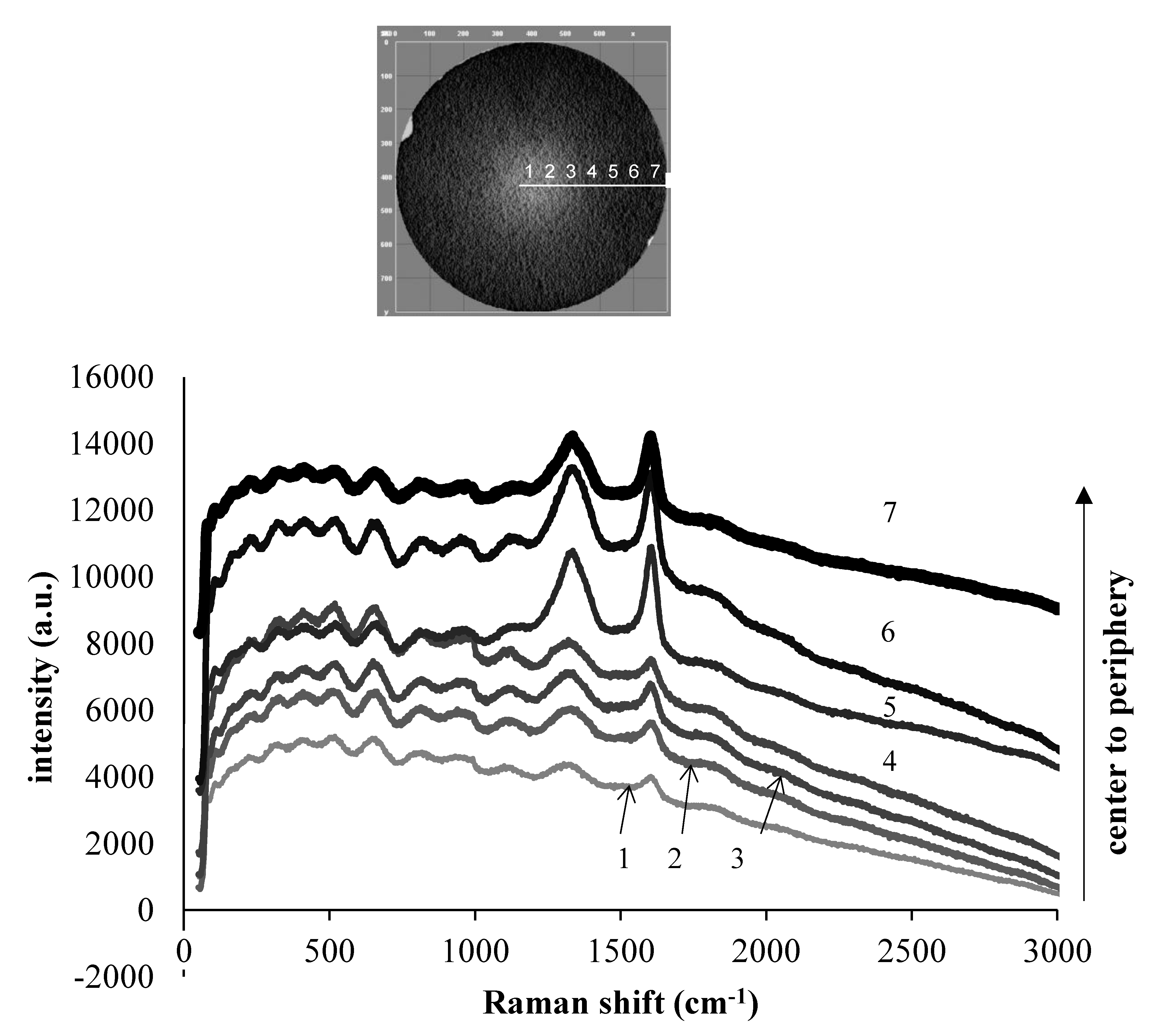
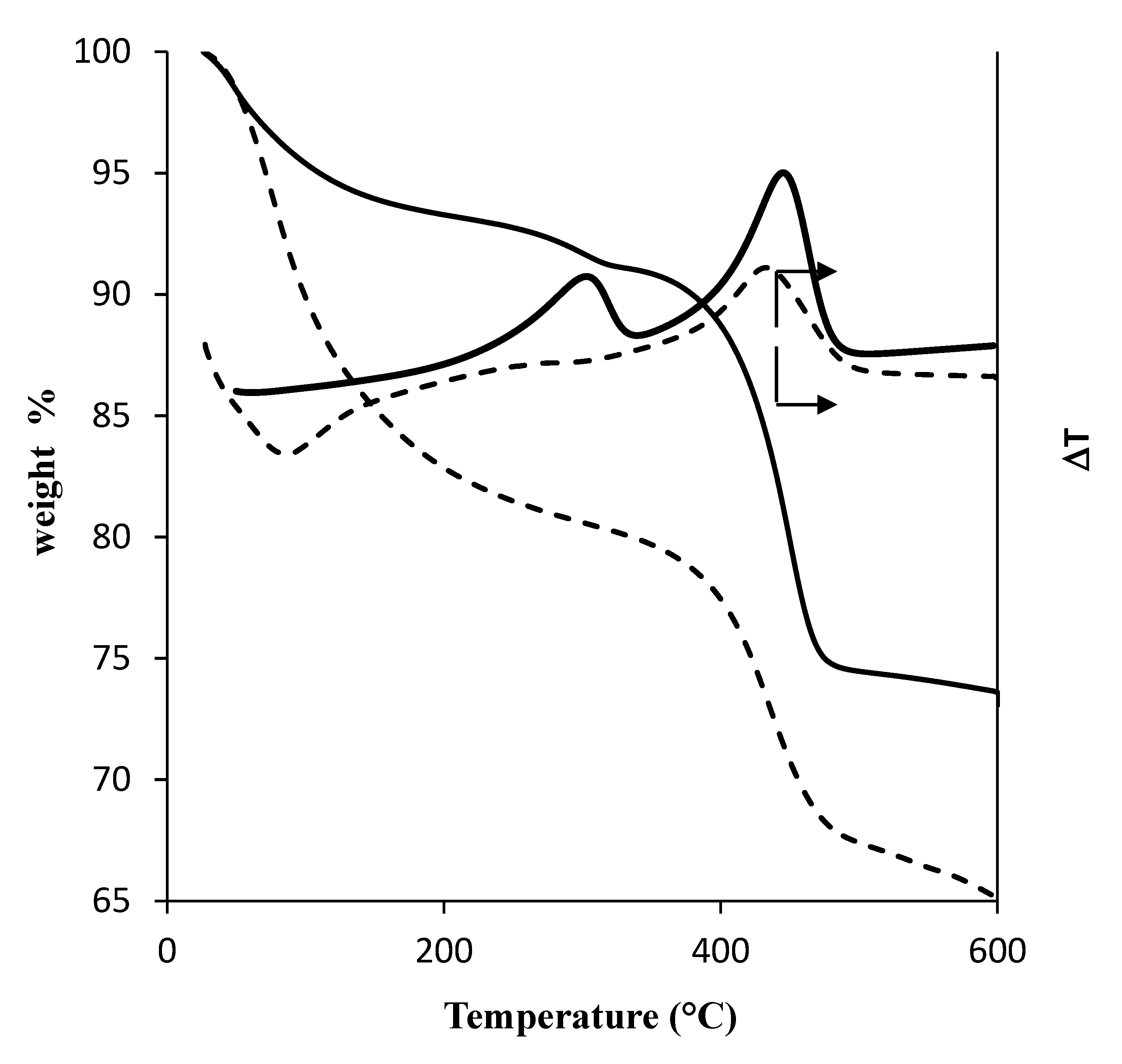
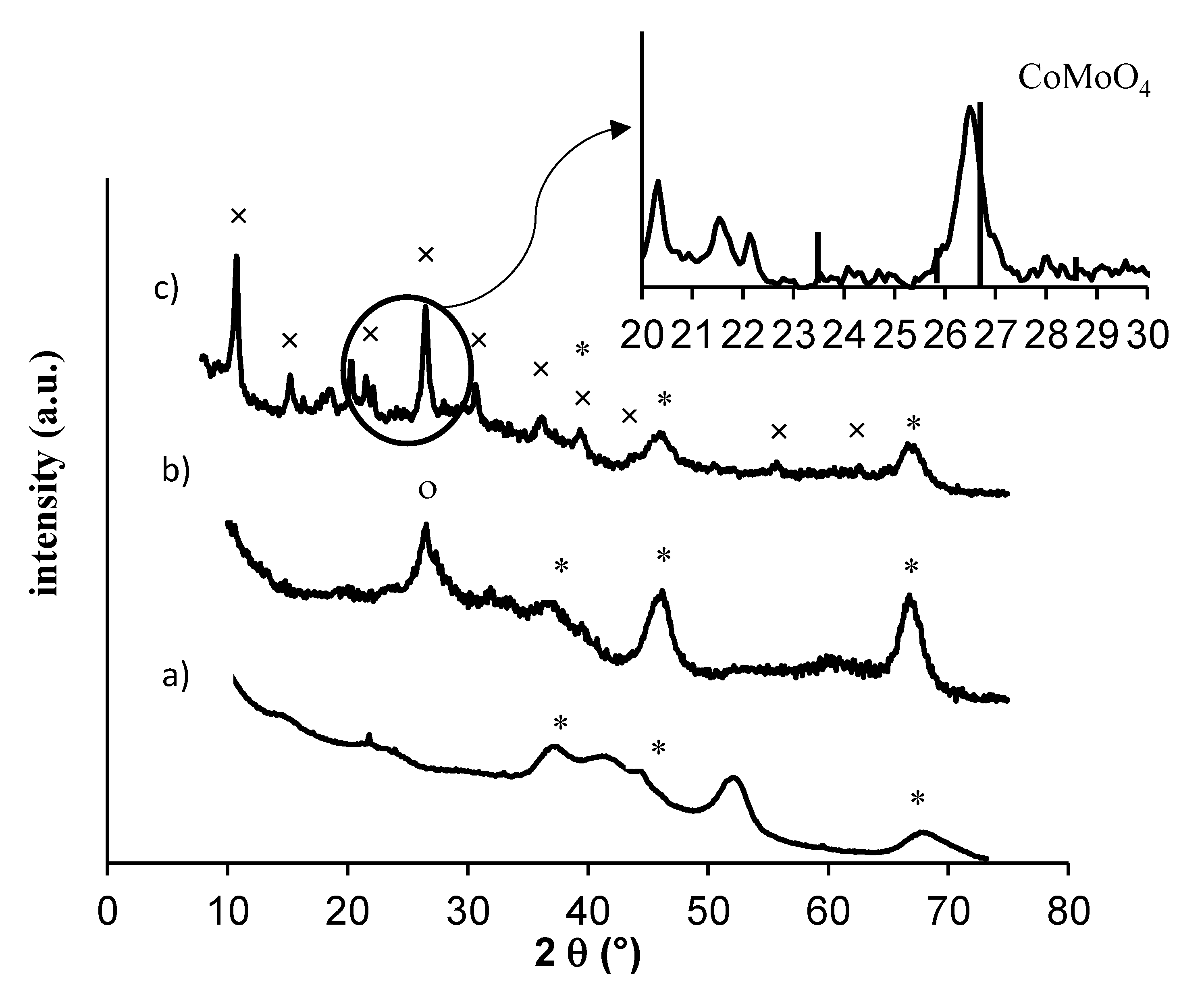
2.1. Characterization of the Catalyst before Plasma Treatment

The amount of molybdenum, cobalt, and phosphorus on the catalyst expressed as their equivalent oxides was: 20.5% MoO3, 4.0% CoO, 5.2% P2O5. They were supported on γ-alumina. Surface areas were determined by the BET method, the amount of carbon and sulfur of used and regenerated catalysts are gathered in Table 1. The values indicated for the coked catalyst were obtained after cleaning by toluene in order to eliminate any light carbon deposited. The amount of coke in the aged catalyst was about 13%, which is the usual amount after two years on stream as well as the amount of sulfur. The regeneration of the aged catalyst at 500 °C under air allowed the total elimination of carbon and sulfur from the catalyst and to recover almost completely the surface area, the fresh catalyst surface area being around 180 m2/g.
After hydrotreating reaction, the coked catalyst (Figure 1a) exhibited the characteristic peak positions and intensities of pseudo-cubic γ-Al2O3 (2θ = 37.59°, 45.84°, 67.00°); there were no Co, Mo diffraction peaks found in the XRD patterns of the supported catalysts over γ-Al2O3 because Co, Mo species were well dispersed on the support.
TGA–TDA analyses were performed for the coked catalyst under an air flow of 100 mL/min and a ramp temperature of 1 °C/min. The profile (Figure 2a) exhibited two exothermic peaks with maxima at 295 and 436 °C. The coupling of TDA with mass (Figure 2b) was performed in order to identify the nature of the species eliminated. The detected fragments m/e = 44 and 64 indicated the presence of a gas phase of CO2 and SO2, respectively, m/z = 48 corresponding to a fragment of SO2 (SO). The results showed that the first weight loss (1.4 wt%) at 295 °C corresponded to the simultaneous elimination of carbon and sulfur compounds, but according to the composition of the coked catalyst (8 wt% in S) it showed that sulfur is only partially removed from the catalyst at low temperatures. Between 300 and 450 °C the weight loss (15.9%) corresponded to the elimination of coke associated with S elimination even if m/e = 64 was not detected, probably due to the low signal intensity. It has been proposed [20] that coke eliminated at low temperatures is localized at the surface of MoS2 particles, the metal favoring coke combustion, while the coke eliminated at higher temperatures could be present at the surface of alumina [21,22].
In order to verify the catalyst composition at different oxidation temperatures, thermal treatments were performed from 250 to 400 °C under air (temperature ramp: 10 °C/min, air flow: 100 mL/min). The amount of carbon and sulfur was determined by elemental analysis and the elimination efficiency is plotted versus temperature in Figure 3. The results confirmed that sulfur is eliminated at low temperature, the sulfur elimination efficiency reached 50% at 250 °C while no coke was eliminated at this temperature. At 300 °C, 80% of sulfur was eliminated and less than 10% of carbon. It appears that the last 20% of sulfur is more difficult to remove and at 400 °C, 14% of S was still present in the catalyst most probably as sulfates. Note that the values of C and S elimination by thermal treatment at fixed temperatures are higher when compared to the values obtained by TGA analysis, which can result from the longer time of exposure to air in the case of thermal treatment.

2.2. Plasma Treatment

The coked hydrotreating catalyst was treated under plasma discharge using a mixture of helium (80 vol%) and oxygen (20 vol%) and a flow rate of 100 mL/min. The deposited power was kept constant at 30W. Images of the wafer after different times of treatment are reported in Figure 4. The brighter color at the center of the disk after 30 minutes of plasma treatment indicates that coke is more easily removed at the center of the wafer, closed to the pin electrode where the electric field is more intense. After 130 minutes of plasma treatment, the periphery of the wafer also appears with grey color. It was interesting to observe that the face in contact with the dielectric material had also changed color from black to grey, indicating that coke was removed on the two faces of the wafer. It suggests that the reactive species generated by plasma are able to diffuse from the surface through the depth of the catalyst wafer or that plasma discharge is formed in the small space between the wafer and the dielectric material. It is supported by a previous study in which we showed that the coke was completely removed in the depth of wafer using coked zeolite material [23].
The concentration in CO2 and CO versus time at the exit of the reactor is reported in Figure 5. Carbon dioxide is mainly obtained by coke oxidation, while CO concentration remains low from the beginning until more than 2 hours of reaction. It is interesting to observe that two maxima are reached for CO2 concentration, the first one after only few minutes of reaction and the second one after about 30 minutes of plasma treatment. From the amount of CO2 and CO quantified, it appears that about 70% of coke was removed after 130 minutes of plasma treatment.
The C, H, N, S elemental analysis after 10, 30, 60, and 130 minutes of plasma treatment was performed and the C, S elimination efficiency was calculated (Figure 6). In accordance with the concentration of CO2 at the exit of the reactor, a rapid elimination of coke was observed during the first hour, while after this period, the coke removal slowed down. The efficiency reached about 70%, corresponding to the amount of CO2 and CO measured at the exit of the reactor. The elimination of sulfur reached a plateau after thirty minutes of plasma treatment, showing that 40% of sulfur was still present in the catalyst after plasma. The amount of hydrogen increased during the reaction (Figure 7). The ratio H/C, initially equal to 1.2, increased until 7.0 after 130 minutes of plasma treatment, confirming coke elimination and suggesting a structural modification of the catalyst due to the presence of water forming under the plasma.

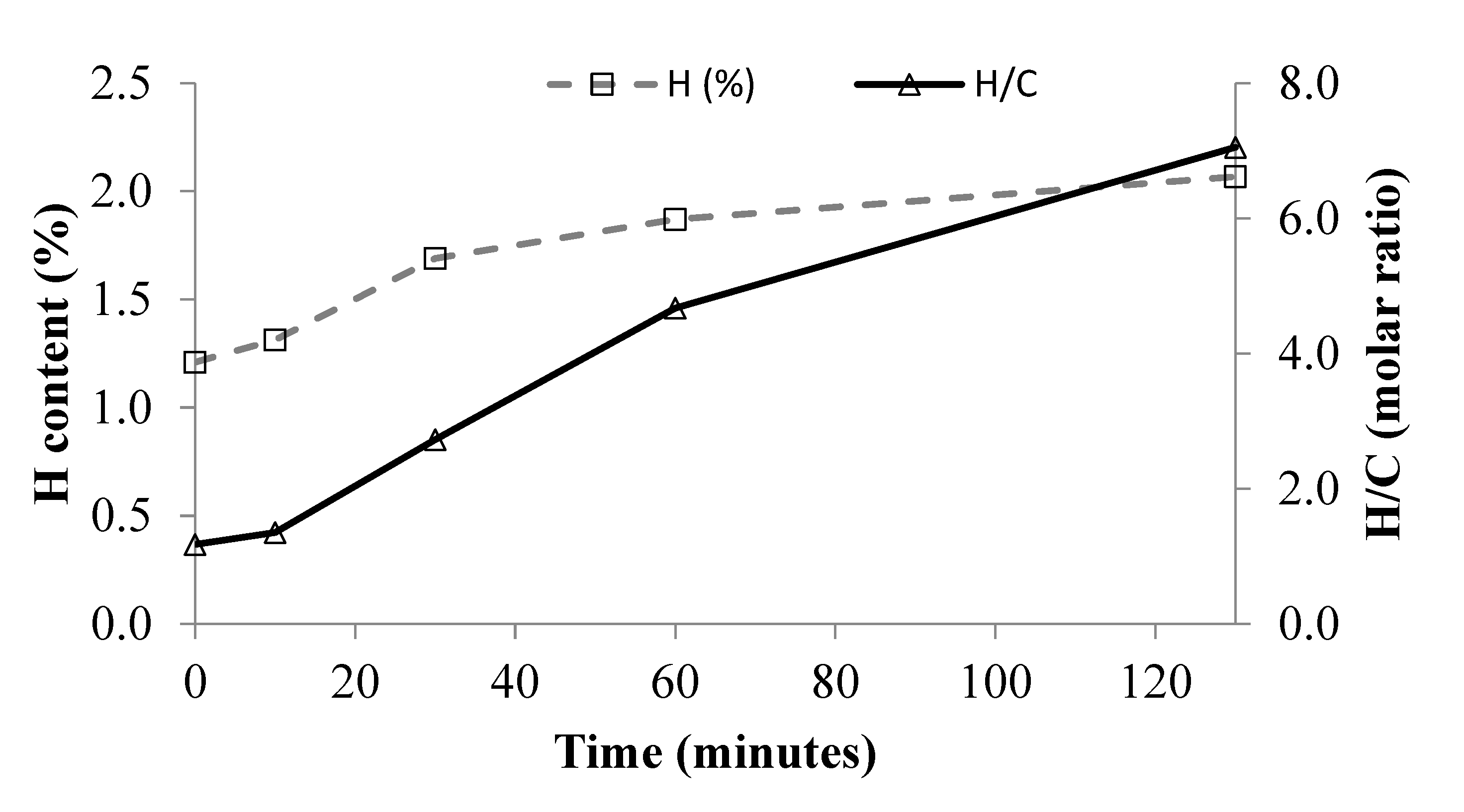
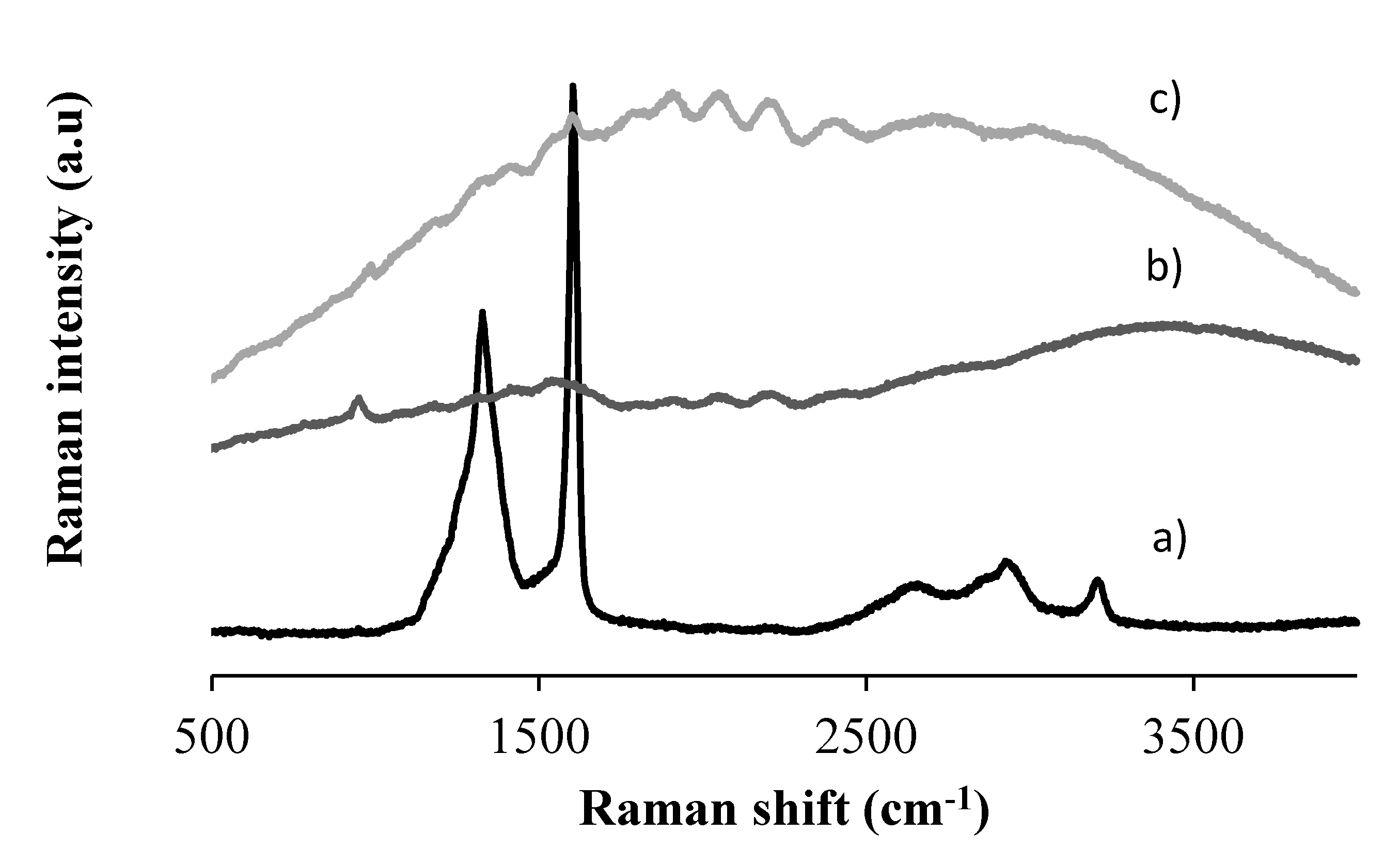
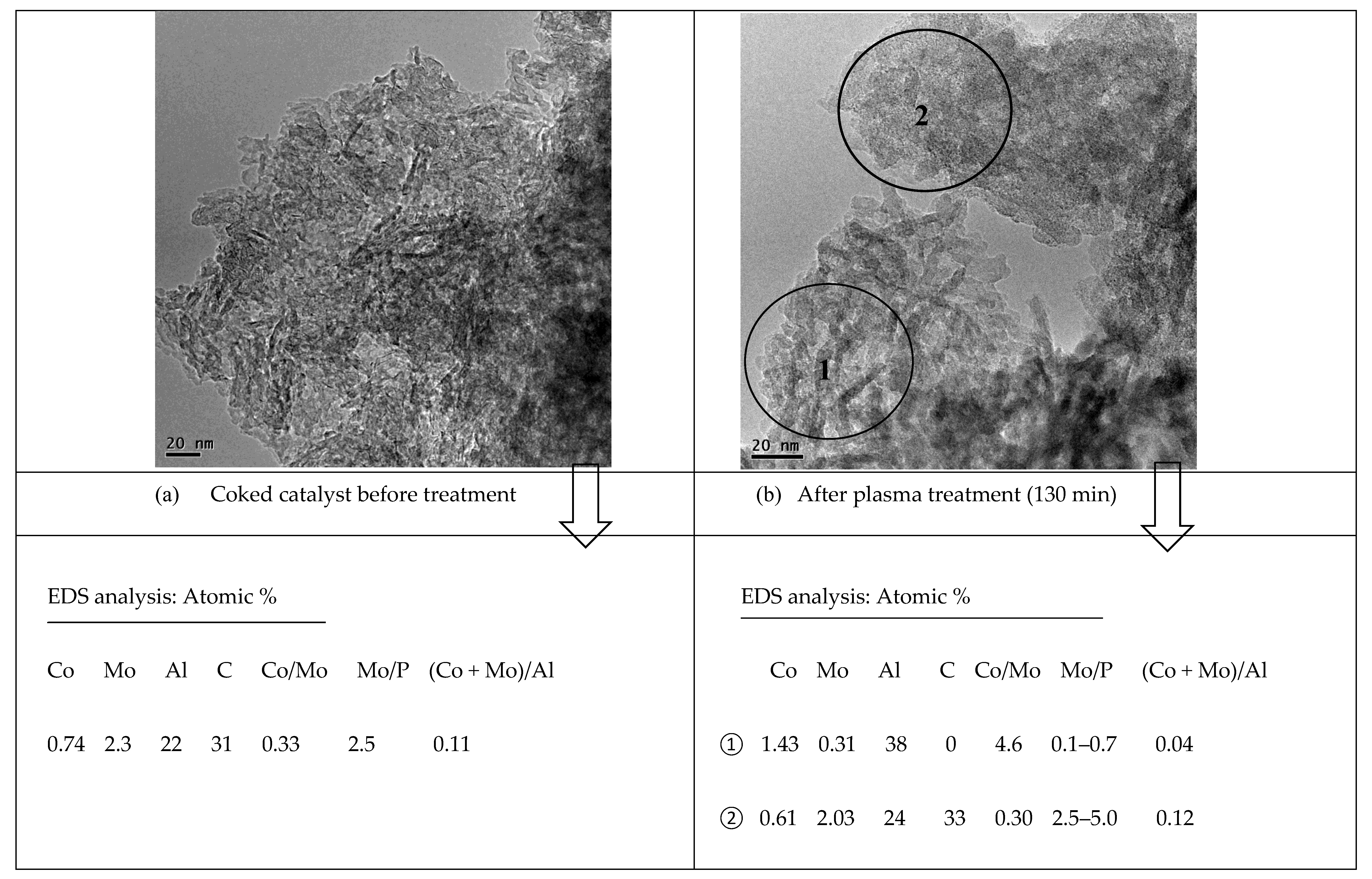
2.3. Characterizations of the Catalyst after Plasma Treatment

The catalyst was characterized by Raman after 130 minutes of plasma treatment (P = 30 W) and compared with the coked catalyst (Figure 8a). As expected, the coked catalyst exhibited the main bands originating from carbon structures: One centered at about 1350 cm−1 (D-band) and the other one at 1600 cm−1 (G-band). A weak shoulder is observed at about 1280 cm−1. According to the Raman spectra obtained and previous studies [18,19], coke deposits can be considered as defective graphitic structures. The structure of the refractory coke is believed to be highly polyaromatic [22]. After thermal treatment at 500 °C, the coke is removed, as seen in Figure 8b). The Raman analysis performed at the center of the wafer after 130 min of plasma treatment exhibited fluorescence, while the characteristic bands of carbon structure were visible at the periphery of the disk, confirming that carbon is more easily removed at the center of the wafer (Figure 9).
The catalyst was characterized after plasma treatment (130 min) by XRD. For comparison, XRD pattern after a classical thermal treatment under air flow, at 500 °C, is also shown in Figure 1. As already reported, a thermal treatment leads to the formation of the CoMoO4 phase (JCPDS 21-0868) at 2θ 26.7°, which is inactive in hydrotreating process. This phase interestingly is not observed after plasma treatment but the formation of an unexpected phase is visible, which corresponds to the heteropolycompound ammonium oxonium dodecamolybdophosphate H11.6Mo12N2.6O40.4P (ICSD: 98-0105-7859), a Keggin HPA PMo12O403− with (NH4)+ as counterion. The presence of nitrogen does not come from gas phase, since the plasma treatment was performed using a mixture of helium and oxygen. The elementary analysis confirmed that nitrogen was a component of the coked catalyst (0.1 wt%), due to the presence of N-containing molecules in the gas oil feed. The mechanism of the Keggin HPA formation under plasma discharge is difficult to explain. The preparation of heteropolyanions having the Keggin type structure by dissolution of MoO3 oxide in the presence of phosphoric acid has been reported [24,25]. Under plasma discharge, water is produced during coke oxidation, its condensation into the pores of alumina can be expected, further reaction between acidified water and oxides would lead to the formation of the polymeric species.
Moreover, the use of heteropolyanion (HPA) as hydrotreating catalyst precursors has been reported by different authors [26,27,28]. They demonstrate a high catalytic activity in the conversion of thiophene by using sulfide catalysts prepared from phosphomobybdates. However they are usually not so well crystallized at the surface of HDT catalysts. If too well crystalized, they could be stable and thus difficult to be sulfided. This is why the evaluation of such a material could be the subject of future studies to demonstrate its potential in the HDS process.
TGA–TDA analyses were performed after 130 min of plasma treatment (Figure 10). An important weight loss is observed at low temperature which can be partly attributed to the elimination of water physisorbed at the surface of the catalyst, water resulting from the oxidation of coke under the discharge. The presence of an endotherm curve at low temperature suggests the loss of water molecules associated with Keggin anion of the HPA phase, as proposed by Tatibouët et al. [29]. At higher temperatures, the exotherm centered at 436 °C can be assigned to the oxidation of the remaining coke but also to the collapse of the Keggin structure and to the crystallization of the resulting oxides [30]. Moreover, the first exothermal peak centered at 295 °C disappeared after 130 minutes of plasma treatment, suggesting the complete elimination of coke from the surface of MoS2.
TEM micrographs of the catalyst before and after plasma treatment are shown in Figure 11. The TEM image in Figure 11a exhibits MoS2 slabs, homogenously dispersed on the alumina support. The slab length is comprised between 5 and 10 nm with a stacking of 1 or 2 slabs. Note that after aging, the presence of carbon deposition does not alter the catalyst morphology, as has been proved by different authors [4,31]. After 130 minutes of plasma treatment under oxygen and helium with a deposited power of 30W, it is interesting to observe two distinct zones of the catalyst. As shown in Figure 11b, in zone ① no carbon was detected by EDS analysis while in zone ② the amount of C reached 33% (atomic). The measurements were performed on ten different points of the zone represented by circles. Note that the size of the probe was 10 nm and the measurement was performed in 50 nm depth of the sample. Consequently it is possible to give only average values of atomic concentration, which do not correspond to the stoichiometric composition of phases due to the high dispersion of metallic species at the surface of the alumina support. The atomic concentrations in zone ②, i.e., with high amount of carbon, were not significantly different from those determined for the sample before treatment, whereas in the area where carbon was eliminated, the Co/Mo ratio reached 4.6. Moreover this zone was characterized by a high amount of alumina ((Co + Mo)/Al = 0.04) and a ratio Mo/P lower than unity. The quantification by EDS confirmed the structural catalyst modification under the plasma discharge, as shown also by XRD analysis.

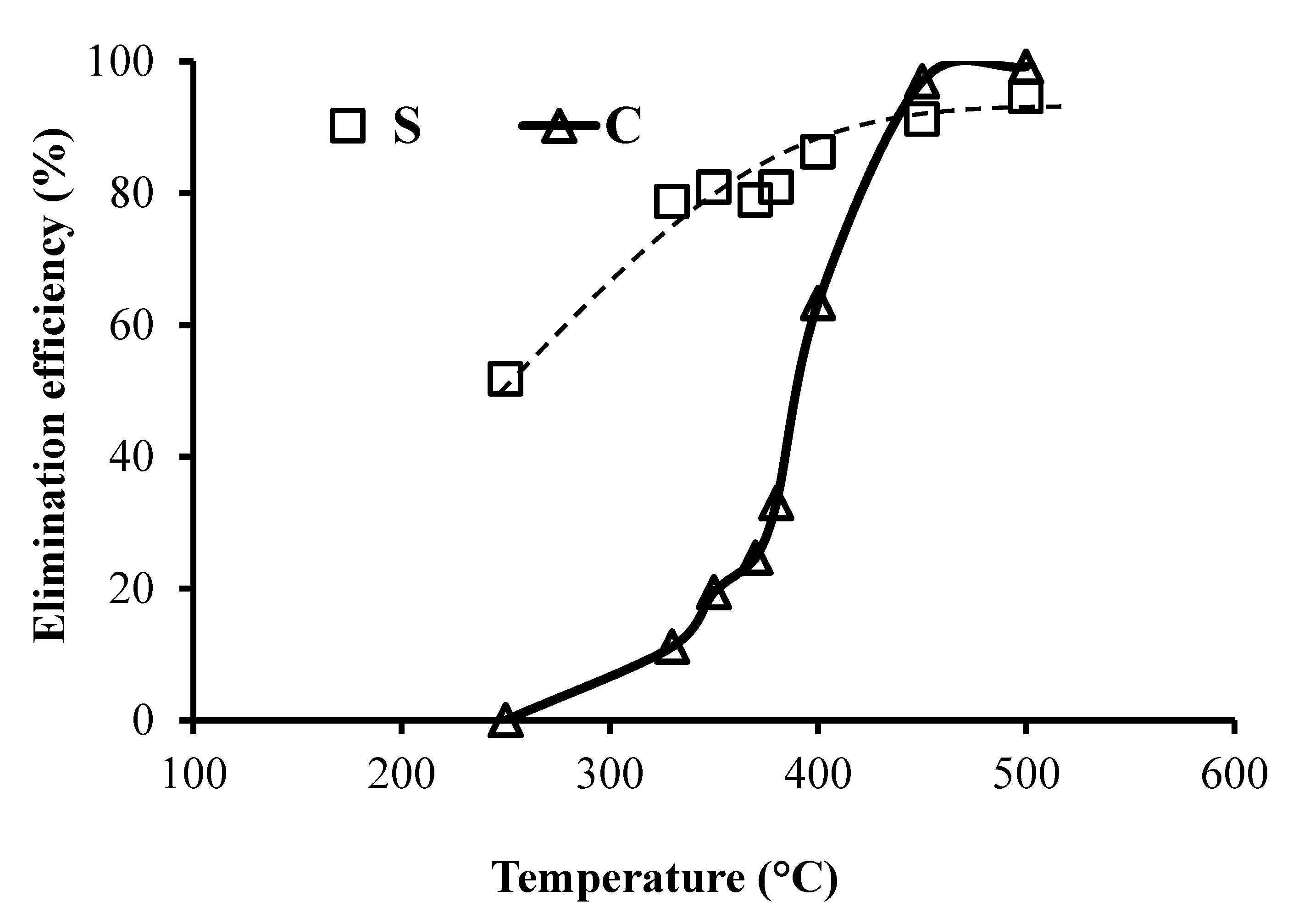
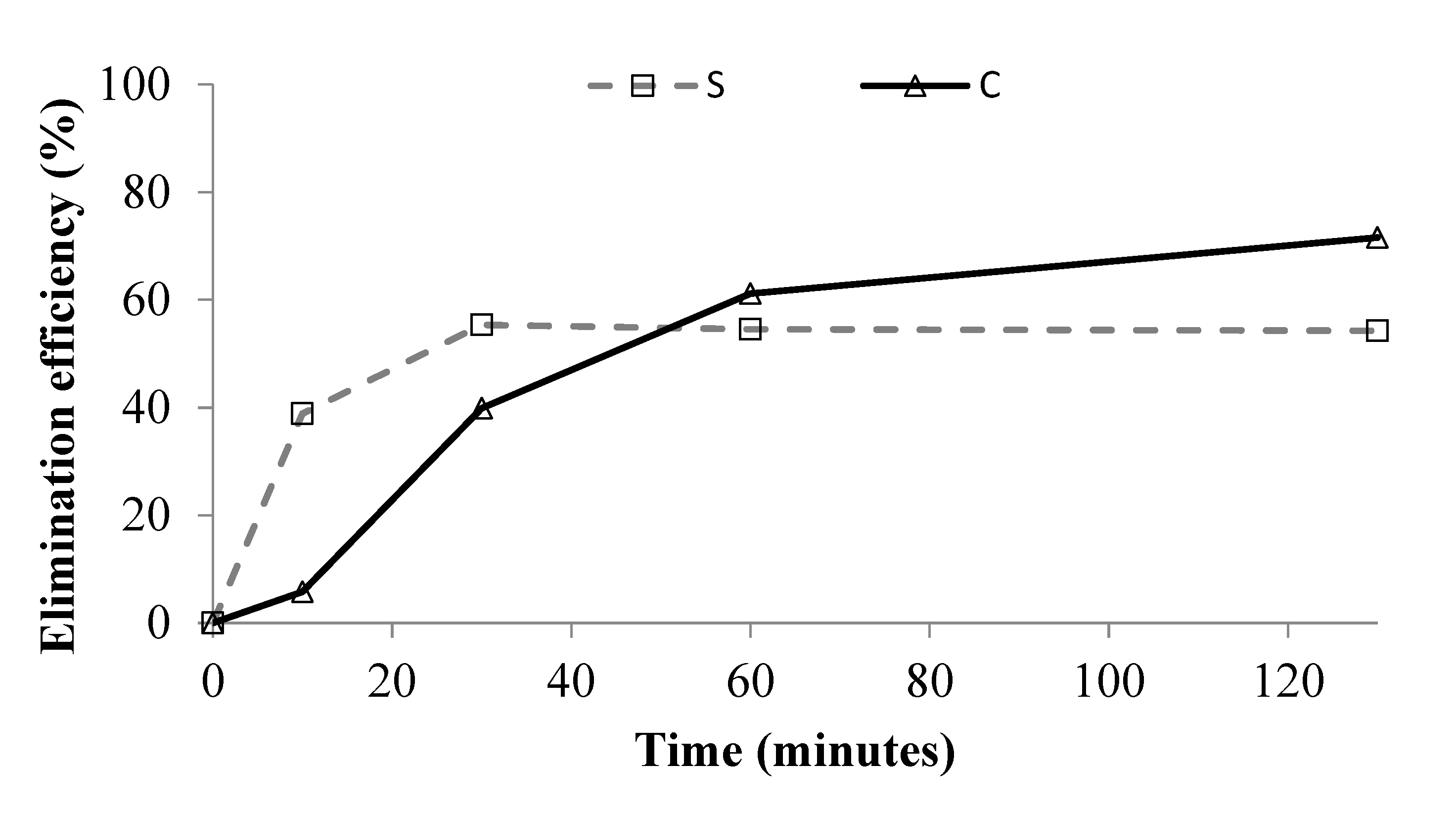
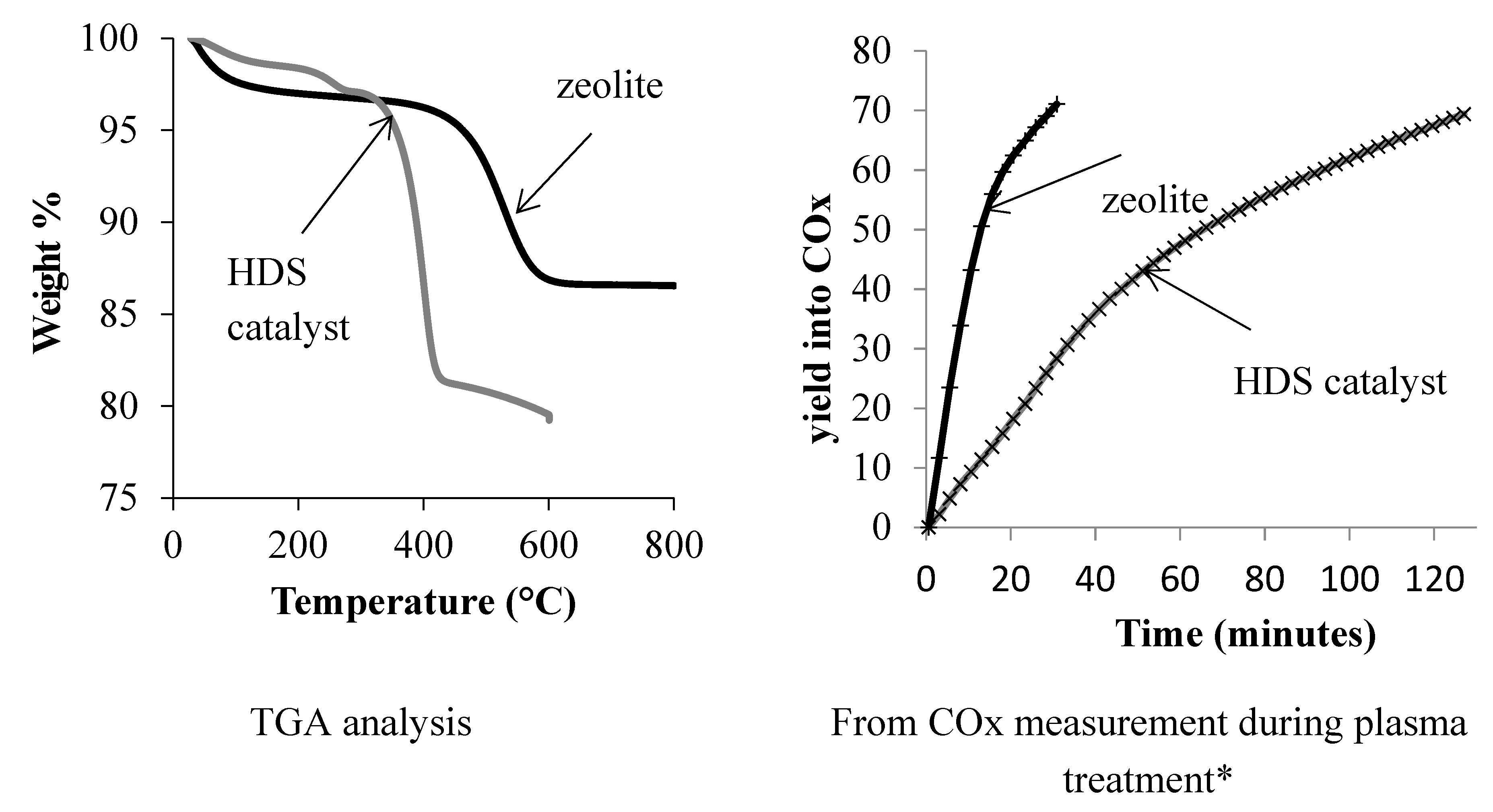
2.4. Comparison between Coke Removal in Zeolite and HDS Catalyst

The thermal stability of coke in the HDS catalyst is lower than in a zeolite, as shown by the TGA profile in Figure 12. The nature and amount of coke differs for the two materials; alkylbenzene and alkylnaphtalene occupy the microporosity of the zeolite while poly-aromatic compounds are present in the HDS catalyst (Table 2). A complete coke removal is reached at 400 °C in the HDS catalyst while 580 °C is required to completely eliminate coke in the zeolite. The presence of metal particles in HDS catalyst can favor coke combustion at lower temperature, as explain before. Regarding zeolite regeneration, the oxidation temperature does not depend on the coke content [32] but mainly on the accessibility of oxygen to coke [33].
The coke deposited on HZSM-5 zeolite is more hydrogenated than that deposited on the HDS catalyst (Table 2). It is worth mentioning that the coke combustion in air is slower on zeolite than on the HDS catalyst despite the highly hydrogenated nature of coke trapped in the micropore.
So, the regeneration is strongly limited by the diffusion of oxygen in the plugged pores. It is difficult to burn it when its content is very high (20 wt%), because of a complete blockage of the access to micropores. It is interesting to observe an opposite trend as soon as plasma is used for coke elimination. The rate of CO2 formation is about five time higher for a zeolite than for the HDS catalyst (Table 2). Indeed, in a previous paper [34], we demonstrated that oxidation rate under plasma discharge depends strongly on the nature of the coke. Higher character polycyclic compounds of coke lower their reactivity relative to the short-lived oxygenated specie. On the zeolite the coke is constituted of polyaromatic molecules not exceeding 5 to 8 aromatic rings, whilst on the HDS catalyst it is graphitic (Figure 13).
The analysis of gas phase under plasma discharge reveals that a large amount of ozone is produced under the experimental conditions used. It is interesting to observe that ozone concentration is more than five times higher in the presence of a zeolite than with the HDS catalyst. It is known that ozone is formed through the dissociation of the O2 molecule followed by a three-body reaction according to [35]: O + O2 + O2 → O3 + O2 k = 8.6.10−31 T−1.25 [36].
So, it is possible to propose that a correlation exists between the amount of ozone formed and the amount of active oxygen species produced, these species being responsible for coke oxidation. With zeolite, the formation of O species is favored in gaseous phase—parts of O-atoms react with coke yielding CO2, while other O-atoms combine with O2 molecules to produce O3. Note that direct oxidation of the coke by ozone can be excluded since the temperature measured in the reactor is too low to activate O3 (always lower than 80 °C). As soon as the coked HDS catalyst is introduced into the discharge, the presence of metal species (Co, Mo) could be responsible for the limitation of O species production or to the fast recombination of active species at the metallic surface of the catalyst [37,38]. As a consequence, under classical thermal oxidation experimental conditions, the presence of metal species improves the activation of oxygen favoring coke combustion at low temperatures, while under nonthermal plasma the metal species inhibit the formation of the active O-atom species and coke elimination is more difficult to achieve.

3. Experimental

3.1. Coked Hydrotreating Catalyst, Characterization

The coked catalyst used to perform the experiments was recovered from a HDS process, after deactivation corresponding to two years on stream. This was a CoMoP with a corresponding oxide (4.0/20.5/5.2) catalyst supported on γ-alumina. The regenerated catalyst, free of coke, was also provided as a reference for the plasma treatment.
Surface areas were measured according to the BET procedure. The nitrogen adsorption–desorption isotherms were determined with a Micromeritics Flowsorb II 2300 appartus at −196 °C. Thermogravimetric analysis were performed with a SDTQ600TA analyser under a 100 mL/min flow of air up to 1173 K. The TGA-mass analysis was performed using a heated transfer line (300 °C) from TGA to the Hiden Analytical QGA (200 uma) apparatus.
High resolution transmission electron microscopy (HRTEM) was carried out using a JEOL 2100 UHR instrument with a LaB6 filament, at 200 kV accelerating voltage. Microanalysis of C, Mo, Al, and Co was carried out by Energy Dispersive X-ray spectroscopy (EDX) in the nanoprobe mode.
The catalysts were characterized by X-ray Diffraction (XRD) using a Siemens D-5005 diffractometer with CuKα = 1.5417Å, operated at 40kV and 30mA. The diffraction patterns were recorded in the 2θ range of 10–90° with a step interval of 0.02° and a period of 1 s.
Raman spectra of carbon nanotubes were obtained using a Labram HR800UV Horiba Jobin Yvon. Patterns were recorded at a wavelength of 532 nm from 10 to 4000 cm−1 with a step size of 1.5 cm−1 and 20 s per step. In order to acquire statistically meaningful data, between 10 to 15 spectra were recorded for each sample.

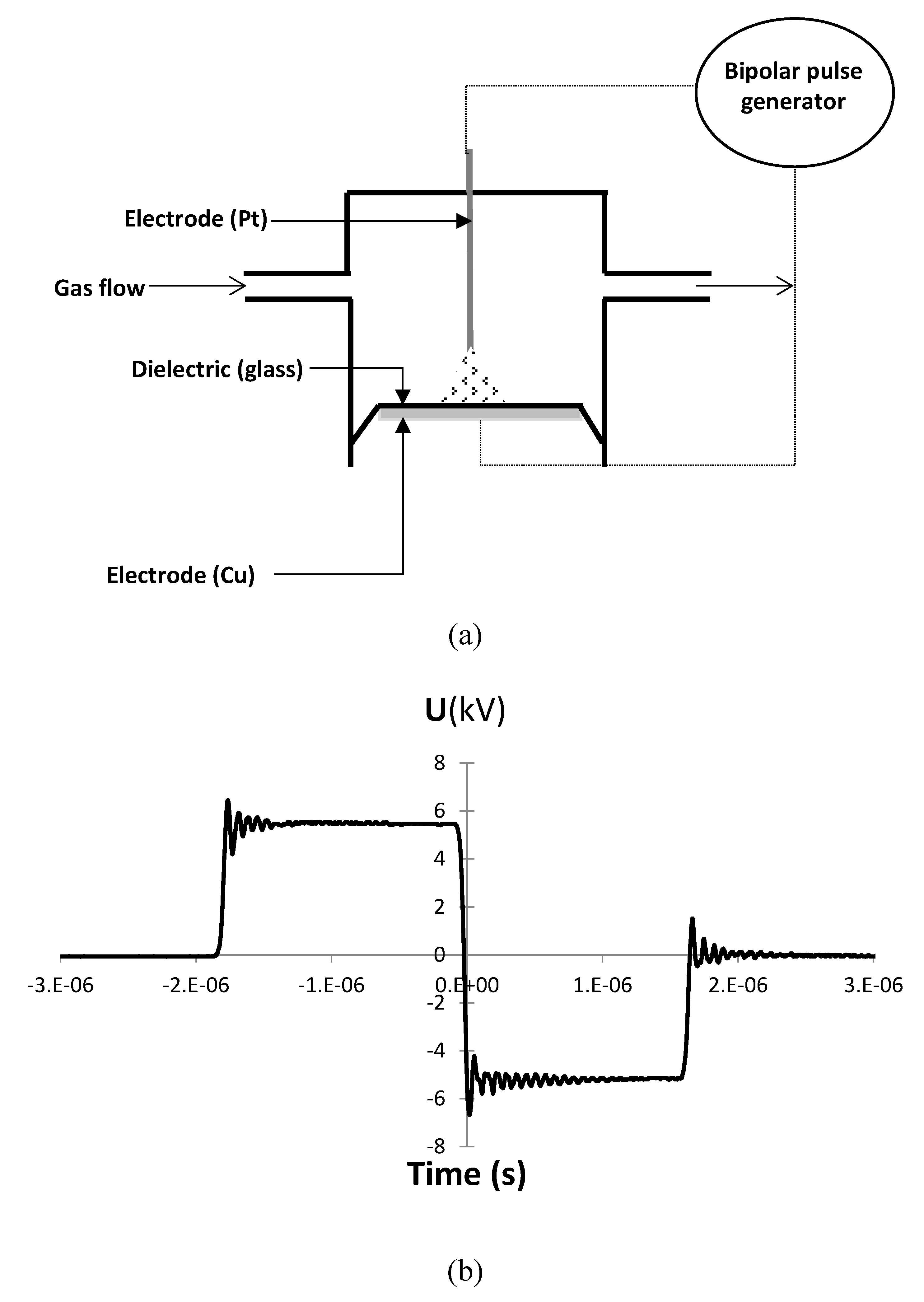
3.2. Pin to Plate Dielectric Barrier Discharge (DBD) Reactor

The reactor used for studying the coke regeneration reaction is a volumetric type dielectric barrier discharge reactor with a pin to plate geometry (Figure 13). One electrode is a stainless-steel pin covered by a platinum deposit (d = 1 mm) and the second electrode is made a copper tape (22 mm in diameter), the two electrodes being separated by a glass plate as dielectric material. The sample is placed in the center of the reactor at the surface of the glass plate. The two electrodes are connected to a bipolar pulse generator (A2E Technologies-Enertronic). The applied voltage is measured using two high-voltage probes (Lecroy, PMK-14KV-AC) and the current intensity by an inductive probe. All electrical signals are visualized and recorded using a digital touchscreen oscilloscope (Lecroy WaveSurfer 64Xs-A, 600MHz).
The bipolar pulse is defined by two consecutive pulses U+ and U applied to one electrode and then to the other, whence U (t) = U+ + U (Figure 1b).
The deposited energy is calculated by temporally integrating the product U (t) by I (t) over the duration of the pulse t as shown by the following equation:
E = U × I × dt
The average power P is calculated according to
P = E × f
with P—power in Watt, E—energy in Joule and f—frequency in Hz.
In this study the deposited power was fixed at 30W, the voltage and frequency being maintained at 12 kV and 2000 Hz, respectively.

3.3. Experimental Reaction Conditions

The reaction was performed by flowing a mixture of helium and oxygen (20 vol% O2) at a constant flow rate: 100 mL/min−1. The weight of the coked catalyst, used as a wafer, was between 20 to 25 mg. The gap between the pin and the wafer was equal to 2.5 mm, the pulse frequency and applied voltage were respectively fixed at 2 kHz and 12 kV, corresponding to a deposited power of 30 W.
The carbon and sulfur elimination efficiency is calculated according to
coke elimination efficiency = ( % coke ) 0 ( % coke ) t ( % coke ) 0 × 100
sulfur elimination efficiency = ( % S ) 0 ( % S ) t ( % S ) 0 × 100
where (%coke)0 and (%coke)t correspond to the amount of coke before and after plasma treatment, respectively.

4. Conclusions

The regeneration of a coked HDS catalyst was investigated using a DBD plasma reactor with a pin to plate geometry, the catalyst being used as a wafer and deposited at the surface of the dielectric material. We show in this study that 70% of coke was eliminated after 130 min of plasma treatment under a mixture of helium and oxygen (He–O2: 80–20 mL/min) and a deposited power of 30 W. The sulfur elimination reached a plateau after thirty minutes of plasma treatment, showing that more than 40% of sulfur was still present in the catalyst after plasma treatment, most probably as sulfates and/or MoS2. Moreover the results showed that treatment of the coked HDS catalyst by plasma under an oxidant media is much more difficult than the treatment of a coked zeolite material, while it is the opposite for a classical thermal treatment. It is believed that the presence of metal species affects the formation of active O-atom species, as shown by the lower ozone concentration in the gaseous phase. Interestingly, even if the rate of coke elimination is lower for the HDS catalyst, the usual refractory species CoMoO4 is not observed, while an unexpected phase was formed under plasma discharge, which belongs to the family of Keggin HPA PMo12O403−. The study will be completed in order to verify if this phase formed under plasma can be an interesting precursor of catalyst for the HDS process, even if it is well crystallized. Moreover, the coke removal by coupling plasma and a thermal treatment at low temperature will be investigated. It is expected that an increase of temperature until 200 °C would allow the activation of ozone formed under plasma and that the efficiency of the process can be improved.

Author Contributions

Data curation, H.S.; A.A. (Ammar Alnaboulsi); A.A. (Amir Astafan); Investigation, J.T.; T.H.; writing—original draft preparation, C.B.-D.; writing—review and editing, C.B.-D.; supervision, E.D.; L.P.

Funding

The authors greatefully aknowledge IFPEN for the financial support. Amir Astafan, thanks the Programme PAUSE and the University of Poitiers for their financial supports. The authors acknowledge financial support from the European Union (ERDF) and “Région Nouvelle Aquitaine”. Hawraa Srour thanks the Lebanese University for the PhD grant.

Conflicts of Interest

The authors declare no conflict of interest.

References

  1. Knudsen, K.G.; Cooper, B.H.; Topsøe, H. Catalyst and process technologies for ultra low sulfur diesel. Appl. Catal. A 1999, 189, 205–215. [Google Scholar] [CrossRef]
  2. Liu, H.; Bao, S.; Cai, Z.; Xu, T.; Li, N.; Wang, L.; Chen, H.; Lu, W.; Chen, W. A novel method for ultra-deep desulfurization of liquid fuels at room temperature. Chem. Eng. J. 2017, 317, 1092–1098. [Google Scholar] [CrossRef]
  3. Rob Van Veen, J.A. What’s new? On the development of sulphidic HT catalysts before the molecular aspects. Catal. Today 2017, 292, 2–25. [Google Scholar] [CrossRef]
  4. Hamiye, R.; Lancelot, C.; Blanchard, P.; Toufaily, J.; Hamieh, T.; Lamonier, C. Diesel HDS performance of alumina supported CoMoP catalysts modified by sulfone molecules produced by ODS process. Fuels 2017, 210, 666–673. [Google Scholar] [CrossRef]
  5. Kasztelan, S.; Toulhoat, H.; Grimblot, J.; Bonnelle, J.P. A geometrical model of the active phase of hydrotreating catalysts. Appl. Catal. 1984, 13, 127–159. [Google Scholar] [CrossRef]
  6. Topsoe, H.; Clausen, B.S.; Candia, R.; Wivel, C.; Morup, S. In situ Mössbauer emission spectroscopy studies of unsupported and supported sulfided Co Mo hydrodesulfurization catalysts: Evidence for and nature of a Co Mo S. J. Catal. 1981, 68, 433–452. [Google Scholar] [CrossRef]
  7. Furimsky, E.; Massoth, F.E. Deactivation of hydroprocessing catalysts. Catal. Today 1999, 52, 381–495. [Google Scholar] [CrossRef]
  8. Dufresne, P. Hydroprocessing catalysts regeneration and recycling. Appl. Catal. A Gen. 2007, 32, 67–75. [Google Scholar] [CrossRef]
  9. Guichard, B. Life Cycle of an HDT Catalyst. In Catalysis by Transition Metal Sulphides from Molecular Theory to Industrial Application; Toulhoat, H., Raybaud, P., Eds.; TechnipFMC: Paris, France, 2013; chap 2.5. [Google Scholar]
  10. Furimsky, E.; Massoth, F.E. Regeneration of hydroprocessing catalysts. Catal. Today 1993, 17, 535–660. [Google Scholar]
  11. Marinkovic-Neduc, R.; Bos kovic, G.; Kis, E.; Lomic, G.; Hantsche, H.; Mic’ic’, R.; Pavlovic, P. Deactivation of industrial hydrotreating Catalyst for middle petroleum fractions processing. Appl. Catal. A 1994, 107, 133–145. [Google Scholar] [CrossRef]
  12. Dufresne, P.; Brahma, N.; Girardier, F. Off-site regeneration of hydroprocessing catalysts. Oil Gas Sci. Technol. 1995, 2, 283–293. [Google Scholar]
  13. Eijsbouts, S. Life cycle of hydroprocessing catalysts and total catalyst management. Stud. Surf. Sci. Catal. 1999, 127, 21–36. [Google Scholar]
  14. Yoshimura, Y.; Sato, T.; Shimada, H.; Matsubayashi, N.; Imamura, M.; Nishijima, A. Oxidative regeneration of spent molybdate and tungstate hydrotreating catalysts. Energy Fuels 1994, 8, 435–445. [Google Scholar] [CrossRef]
  15. Bui, N.Q.; Geantet, C.; Berhault., G. Maleic acid, an efficient additive for the activation of regenerated CoMo/Al2O3 hydrotreating catalysts. J. Catal. 2015, 330, 374–386. [Google Scholar] [CrossRef]
  16. Dasilva, V.; Frety, R.; Schmal, M. Activation and Regeneration of a NiMo/Al2O3 Hydrotreatment Catalyst. Ind. Eng. Chem. Res. 1994, 33, 1692–1699. [Google Scholar]
  17. Khan, M.A.; Al-Jalal, A.A.; Bakhtiari, I.A. Decoking of a coked zeolite catalyst in a glow discharge. Anal. Bioanal. Chem. 2003, 377, 89–96. [Google Scholar] [CrossRef]
  18. Khan, M.A.; Al-Jalal, A.A. Enhanced decoking of a coked zeolite catalyst using a glow discharge in Ar–O2 gas mixture. Appl. Catal. A Gen. 2004, 272, 141–149. [Google Scholar] [CrossRef]
  19. Jia, L.; Al Farouha, M.; Pinard, L.; Hedan, S.; Comparot, J.-D.; Dufour, A.; Ben Tayeb, K.; Vezin, H.; Batiot-Dupeyrat, C. New routes for complete regeneration of coked zeolite. Appl. Catal. B Environ. 2017, 219, 82–91. [Google Scholar] [CrossRef]
  20. Guichard, B.; Roy-Auberger, M.; Devers, E.; Rebours, B.; Quoineaud, A.; Digne, M. Characterization of aged hydrotreating catalysts. Part I: Coke depositions, study on the chemical nature and environment. Appl. Catal. A Gen. 2009, 367, 1–8. [Google Scholar] [CrossRef]
  21. Le Minh, C.; Jones, R.A.; Craven, I.E.; Brown, T.C. Temperature-Programmed Oxidation of Coke Deposited on Cracking Catalysts: Combustion Mechanism Dependence. Energy Fuels 1997, 11, 463–469. [Google Scholar] [CrossRef]
  22. Callejas, M.A.; Martınez, M.T.; Blasco, T.; Sastre, E. Coke characterisation in aged residue hydrotreating catalysts by solid-state 13C-NMR spectroscopy and temperature-programmed oxidation. Appl. Catal. A Gen. 2001, 218, 181–188. [Google Scholar] [CrossRef]
  23. Pinard, L.; Ayoub, N.; Batiot-Dupeyrat, C. Regeneration of a Coked Zeolite via Nonthermal Plasma Process: A Parametric Study. Plasma Chem. Plasma Process. 2019, 39, 929–936. [Google Scholar] [CrossRef]
  24. Griboval, A.; Blanchard, P.; Payen, E.; Fournier, M.; Dubois, J.L. Alumina supported HDS catalysts prepared by impregnation with new heteropolycompounds. Comparison with catalysts prepared by conventional Co–Mo–P. Catal. Today 1998, 45, 277–283. [Google Scholar] [CrossRef]
  25. Griboval, A.; Blanchard, P.; Payen, E.; Founier, M.; Dubois, J.L. Alumina supported HDS catalysts prepared by impregnation with new heteropolycompounds. Stud. Surf. Sci. Catal. 1997, 106, 181–193. [Google Scholar]
  26. Breysse, M.; Geantet, C.; Afanasiev, P.; Blanchard, J.; Vrinat, M. Recent studies on the preparation, activation and design of active phases and supports of hydrotreating catalysts. Catal. Today 2008, 130, 3–13. [Google Scholar] [CrossRef]
  27. Lamonier, C.; Martin, C.; Mazurelle, J.; Harle, V.; Guillaume, D.; Payen, E. Molybdocobaltate cobalt salts: New starting materials for hydrotreating catalysts. Appl. Catal. B Environ. 2007, 70, 548–556. [Google Scholar] [CrossRef]
  28. North, J.; Poole, O.; Alotaibi, A.; Bayahia, H.; Kozhevnikova, E.F.; Alsalme, A.; Siddiqui, M.R.H.; Kozhevnikov, I.V. Efficient hydrodesulfurization catalysts based on Keggin polyoxometalates. Appl. Catal. A Gen. 2015, 508, 16–24. [Google Scholar] [CrossRef]
  29. Tatibouët, J.M.; Montalescot, C.; Brückman, K.; Haber, J.; Che, M.A. Two-step transformation of the magnesium salt of phosphomolybdic acid HMgPMo12O40 supported on silica. J. Catal. 1997, 169, 22–32. [Google Scholar] [CrossRef]
  30. Biellanski, A.; Malecka, A.; Pozniczek, J. DTA and TG analysis of heteropolyacids of the series H(3+x)PMo(12−x)VxO40·nH2O. J. Therm. Anal. 1989, 35, 1699–1707. [Google Scholar] [CrossRef]
  31. Guichard, B.; Roy-Auberger, M.; Devers, E.; Pichon, C.; Legens, C. Characterization of aged hydrotreating catalysts. Part II: The evolution of the mixed phase. Effects of deactivation, activation and/or regeneration. Appl. Catal. A Gen. 2009, 367, 9–22. [Google Scholar] [CrossRef]
  32. Magnoux, P.; Guisnet, M. Coking, ageing and regeneration of zeolites: VI. Comparison of the Rates of Coke Oxidation of HY, H-Mordenite and HZSM-5. Appl. Catal. 1988, 38, 341–352. [Google Scholar] [CrossRef]
  33. Guisnet, M.; Ribeiro, F.R. Deactivation and Regeneration of Zeolite Catalysts, 1st ed.; Imperial College Press: London, UK, 2011. [Google Scholar]
  34. Astafan, A.; Batiot-Dupeyrat, C. Mechanism and Kinetic of Coke Oxidation by Nonthermal Plasma in Fixed-Bed Dielectric Barrier Reactor. J. Phys. Chem. C 2019, 123, 9168–9175. [Google Scholar] [CrossRef]
  35. Eliasson, B.; Kogelschatz, U. Modeling and applications of silent discharge plasmas. IEEE Trans. Plasma Sci. 1991, 19, 309–323. [Google Scholar] [CrossRef]
  36. Stefanovic, I.; Bibinov, N.K.; Deryugin, A.A.; Vinogradov, I.P.; Napartovich, A.P.; Wiesemann, K. Kinetics of ozone and nitric oxides in dielectric barrier discharges in O2/NOx and N2/O2/NOx mixtures. Plasma Sour. Sci. Technol. 2001, 10, 406–416. [Google Scholar] [CrossRef]
  37. Tu, X.; Gallon, H.J.; Twigg, M.V.; Gorry, P.A.; Whitehead, J.C. Dry reforming of methane over a Ni/Al2O3 catalyst in a coaxial dielectric barrier discharge reactor. J. Phys. D Appl. Phys. 2011, 44, 274007–274017. [Google Scholar] [CrossRef]
  38. Jo, S.; Kim, T.; Lee, D.H.; Kang, W.S.; Song, Y.H. Effect of the electric conductivity of a catalyst on methane activation in a dielectric barrier discharge reactor. Plasma Chem. Plasma Process. 2014, 34, 175–186. [Google Scholar] [CrossRef]
Figure 1. XRD patterns: (a) coked catalyst, (b) after thermal regeneration, (c) after plasma treatment. Symbols: ∗ γ-Al2O3, o CoMoO4, × H11.6Mo12N2.6O40.4P.
Catalysts 09 00783 g001
Figure 2. TGA analysis of the coked catalyst: (a) TGA–DTA, (b) TDA–mass.
Catalysts 09 00783 g002
Figure 3. Carbon and sulphur removal by thermal treatment under air at temperatures from 250 to 400 °C, flow rate of air: 100 mL/min, temperature ramp: 10 °C/min.
Catalysts 09 00783 g003
Figure 4. Images of the wafer at different treatment duration under plasma (P = 30 W, He-O2: 80–20 mL/min).
Catalysts 09 00783 g004
Figure 5. Plasma treatment, analysis of gas.
Catalysts 09 00783 g005
Figure 6. Elimination efficiency of carbon and sulphur as a function of treatment time.
Catalysts 09 00783 g006
Figure 7. H weight content and H/C molar ratio as a function of regeneration time.
Catalysts 09 00783 g007
Figure 8. Raman spectra of the catalyst: (a) Coked catalyst, (b) after thermal treatment at 500 °C under air, (c) after plasma treatment: 130 min, P = 30 W.
Catalysts 09 00783 g008
Figure 9. Raman spectra of the catalyst at different locations of the wafer after plasma treatment: 130 minutes, P = 30 W.
Catalysts 09 00783 g009
Figure 10. TGA–TDA analysis after 130 min of plasma treatment (dotted line) and comparison with analysis before treatment (solid line).
Catalysts 09 00783 g010
Figure 11. TEM and EDS analysis (a) before and (b) after plasma treatment (analyses performed in the middle of the wafer).
Catalysts 09 00783 g011
Figure 12. Comparison between a HDS catalyst and a zeolite HMFI for coke removal by nonthermal plasma. * experimental conditions: P ≈ 30W (U = 12kV, f = 2000Hz), flow: 100 mL/min (80% He-20% O2).
Catalysts 09 00783 g012
Figure 13. Plasma reactor: (a) Scheme of the pin to plate dielectric barrier discharge (DBD) reactor, (b) pulse signal.
Catalysts 09 00783 g013
Table 1. Characterization of the fresh and coked HDS catalysts.
CatalystS BET (m2/g)%C **%S
Coked145138
Regenerated *17300
* Regeneration by thermal treatment at 500 °C under air flow. ** Determined by elemental analysis (weight %).
Table 2. Comparison between the coke composition and reactivity toward thermal regeneration and plasma treatment.
CatalystCokeWeight Loss T (°C)Plasma Treatment *
AmountNatureInitial Rate of CO2 Formation (mol CO2/mol C/min)Ozone Concentration (ppm)
Zeolite
H-MFI
10%Alkylbenzene, alkylnaphtalene,
alkylpyrene
5124.541400–1600
HDS catalyst13%2 types: Soft and strong
Catalysts 09 00783 i001
3970.92200–350
* experimental conditions: P ≈ 30W (U = 12kV, f = 2000Hz), flow: 100 mL/min (80% He-20% O2).

