Article

Fischer–Tropsch: Product Selectivity–The Fingerprint of Synthetic Fuels

1
Asbury University, One Macklem Drive, Wilmore, KY 40390, USA
2
Center for Applied Energy Research, University of Kentucky, 2540 Research Park Dr., Lexington, KY 40511, USA
3
Faraday Energy, 1525 Bull Lea Rd. Suite # 5, Lexington, KY 40511, USA
4
Department of Chemical Engineering, Norwegian University of Science and Technology, N-7491 Trondheim, Norway
5
Department of Civil and Chemical Engineering, University of South Africa, Private Bag X6, Florida 1710, South Africa
6
Chemical Engineering Program—Department of Biomedical Engineering, and Department of Mechanical Engineering University of Texas at San Antonio, 1 UTSA Circle, San Antonio, TX 78249, USA
*
Author to whom correspondence should be addressed.
Catalysts 2019, 9(3), 259; https://doi.org/10.3390/catal9030259
Submission received: 16 February 2019 / Revised: 3 March 2019 / Accepted: 7 March 2019 / Published: 14 March 2019
(This article belongs to the Special Issue Iron and Cobalt Catalysts)

Abstract

:
The bulk of the products that were synthesized from Fischer–Tropsch synthesis (FTS) is a wide range (C1–C70+) of hydrocarbons, primarily straight-chained paraffins. Additional hydrocarbon products, which can also be a majority, are linear olefins, specifically: 1-olefin, trans-2-olefin, and cis-2-olefin. Minor hydrocarbon products can include isomerized hydrocarbons, predominantly methyl-branched paraffin, cyclic hydrocarbons mainly derived from high-temperature FTS and internal olefins. Combined, these products provide 80–95% of the total products (excluding CO2) generated from syngas. A vast number of different oxygenated species, such as aldehydes, ketones, acids, and alcohols, are also embedded in this product range. These materials can be used to probe the FTS mechanism or to produce alternative chemicals. The purpose of this article is to compare the product selectivity over several FTS catalysts. Discussions center on typical product selectivity of commonly used catalysts, as well as some uncommon formulations that display selectivity anomalies. Reaction tests were conducted while using an isothermal continuously stirred tank reactor. Carbon mole percentages of CO that are converted to specific materials for Co, Fe, and Ru catalysts vary, but they depend on support type (especially with cobalt and ruthenium) and promoters (especially with iron). All three active metals produced linear alcohols as the major oxygenated product. In addition, only iron produced significant selectivities to acids, aldehydes, and ketones. Iron catalysts consistently produced the most isomerized products of the catalysts that were tested. Not only does product selectivity provide a fingerprint of the catalyst formulation, but it also points to a viable proposed mechanistic route.

1. Introduction

1.1. The Heart of the X-to-Liquids Process

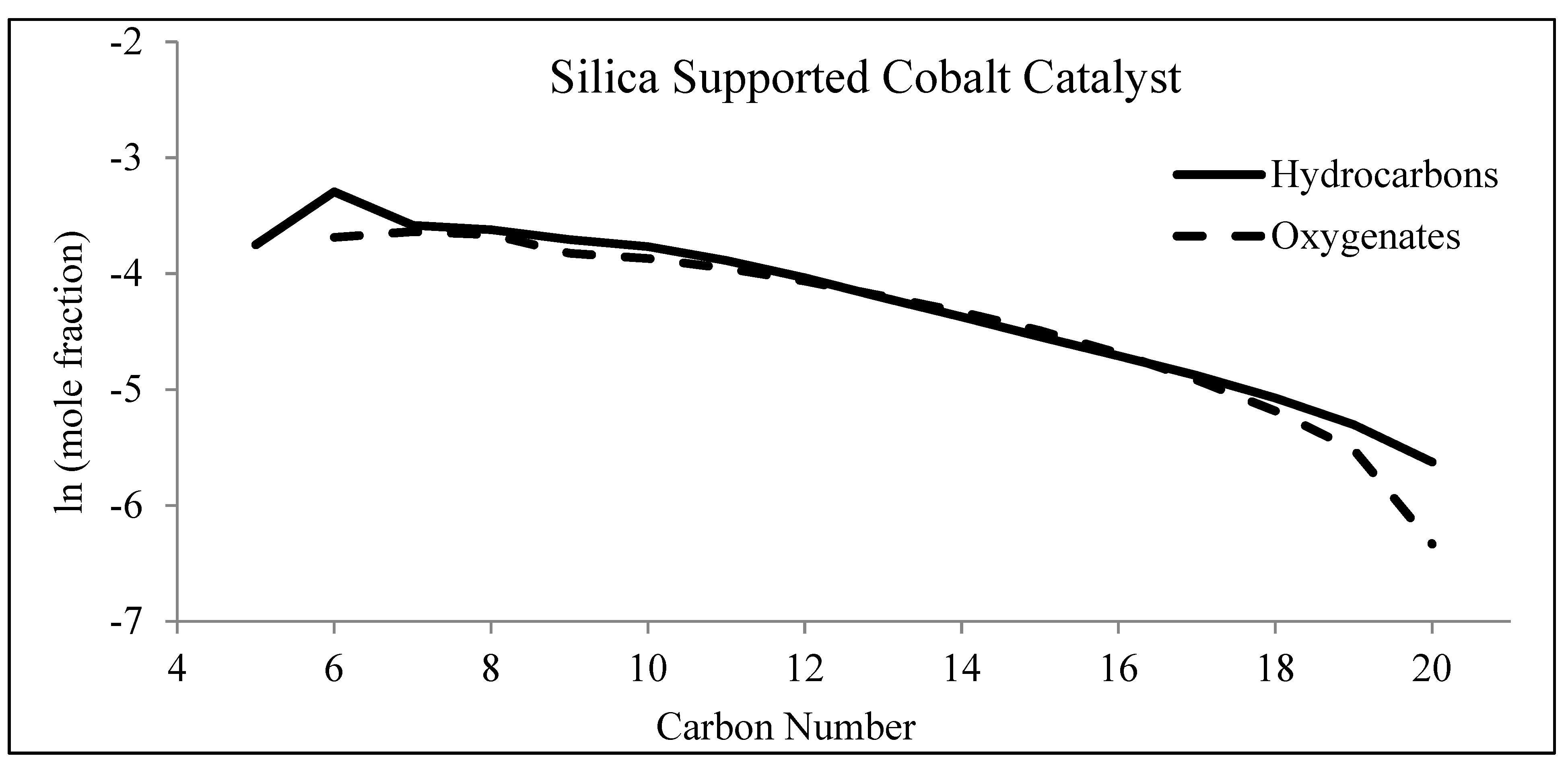
Fischer–Tropsch synthesis (FTS) is a pseudo-polymerization synthesis that is a key step in Gas-to-Liquids (GTL) [1,2,3], Coal-to-Liquids (CTL) [4,5,6,7], and Biomass-to-Liquids (BTL) [8,9,10] processes, as displayed in Figure 1. Briefly, there are three main steps that are undertaken to produce materials. The first step is syngas production from natural resources, primarily materials that are of local natural abundance. To generate the raw syngas, these raw materials are first processed by gasification (in the case of coal or biomass) or steam reforming/partial oxidation (in the case of natural gas). The actual chemistry depends on which raw materials are to be locally utilized. The overall chemical reactions are provided below:
CTL/BTL = C + H2O ⇌ CO + H2 at a H2/CO ratio of 0.7
GTL = CH4 + H2O ⇌ CO + 3 H2
Given the complexities of natural resources, these equations do not include all of the extraneous components, such as heteroatoms (i.e., sulfur, nitrogen), metals, and CO2. Thus, to obtain the needed pure syngas, a cleanup procedure is paired with the gasification process [11,12]. Furthermore, depending on the natural resource used, the off-gas from gasification needs to be treated by a versatile system, because a multitude of components must be eliminated, including: various alkali metals, transition metals, sulfur compounds (i.e., COS, H2S), CO2, nitrogen compounds (i.e., HCN, NH3), and hydrohalic acids (i.e., HCl, HBr). Sulfur elimination is especially important, as it irreversibly binds to the FTS catalyst, poisoning active sites, and altering selectivity.
In the case of low H2/CO syngas (i.e., from coal and/or biomass), water-gas shift (WGS):
WGS H2O + CO ⇌ H2 + CO2   ΔH = −41 kJ/mol
may be used to increase the H2/CO ratio [13]. Iron carbide catalyst is often used in this case, as it is active for both WGS and FTS, which are run simultaneously with a H2/CO ratio that can be as low as ~0.7–1.0 for coal-derived syngas [14,15,16]. The last step is the catalytic upgrading of these hydrocarbons by the hydrocracking of waxes to target the desired hydrocarbon range of interest (e.g., gasoline, jet fuels, diesel, lubricants, etc.) [17].

1.2. Fischer–Tropsch Synthesis

At moderate pressures and temperatures, FTS is employed to convert the synthesis gas to a range of hydrocarbons, which, once upgraded, can be utilized as high quality, almost sulfur-free, fuels (namely diesel and jet fuels), lubricants, waxes, and chemicals [18,19]. The main representative reactions are given by:
n-alkane production: (2n + 1)H2 (g) + nCO (g) → CnH2n+2 + nH2O
alkene production: (2n)H2 (g) + nCO (g) → CnH2n + nH2O
The product slate that is synthesized by FTS is remarkable, ranging from methane up to C70+ [20,21]. Products vary based on reaction conditions (i.e., temperature, pressure, space velocity, and H2/CO ratio), reactor type, and catalyst formulation. Though the identity of the C1 monomer is still under scrutiny [22,23,24,25], FTS is generally assumed to follow a polymerization reaction, whereby:
  • reactants (H2 and CO) chemisorb on active sites;
  • chain growth is initiated;
  • the carbon chain is then propagated;
  • the chain is terminated; and,
  • the final product desorbs from the catalyst surface (with the possibility of minor readsorption and reincorporation [26]).

1.3. Active FTS Metals

As of now, only four transitional metals are considered active for FTS: cobalt, iron, ruthenium, and nickel. Given that nickel has been plagued as a methanation catalyst, and simply due to the price of ruthenium, only cobalt and iron have typically been considered for industrial use to date [27,28]. Iron is the most abundant metal, and it is thus less expensive than cobalt. Iron is also preferred for industrial applications, where coal is the natural resource used to produce the syngas. The low level of H2 in the syngas is due to the high abundance of naphthalene-based materials, molecules that contain more carbon than hydrogen. Iron is also different in that, as understood today, iron carbide, not the metal itself, is the active species. In addition, iron carbide alone is a very low-α (i.e., where α is chain growth probability) catalyst, and normally an alkali promoter, such as potassium, is added to increase the dissociation rate of CO, allowing for α to increase [29,30]. Copper is normally added as a promoter as well, to enhance the reducibility of iron oxides during activation [31].
Cobalt, the other active metal that is utilized in industry for FTS, is normally paired with the GTL process. Cobalt, unlike iron, possesses very low intrinsic WGS activity, and it is thus more useful for higher H2/CO ratio syngas, such as that derived from natural gas. Because cobalt is expensive, it is typically supported on materials, such as Al2O3, SiO2, and TiO2, in order to produce nanoparticles that improve the fraction of exposed surface cobalt atoms [32]. The control of interactions between the active cobalt and the support is a balancing act. Poor interactions lead to the agglomeration of cobalt particles, resulting in lower CO conversion on a per gram catalyst basis [33]. However, if the interaction between the support and the cobalt is too strong, then fine Co particles can lead to low reducibility, and thus reduction promoters (e.g., Pt, Re, and Ru) are often added to facilitate their reduction by hydrogen dissociation and spillover or via a chemical effect [34].

1.4. Supports and Promoters

Research has shown that iron is not as efficient at hydrogenation as cobalt or ruthenium and, as a result, iron produces higher selectivities of olefin and oxygenated products [35]. Formulations of iron catalysts often include silica as a structural stabilizer to help prevent attrition; however, iron catalysts also rely on promoters, such as alkali metals and/or copper, to assist in FTS. Alkali promoters for iron catalysts also promote the formation of the active phase, iron carbide, while copper has been found to facilitate the reduction of iron oxides prior to carbide formation. The typical Fe compounds that are intermediates in the reduction/carburization process in CO are Fe2O3 → Fe3O4 → FeO → FexCy [36]. For cobalt, the promoters, which are often metals, like Pt, Re, and Ru, enhance the degree of reduction of cobalt oxides, and most significantly that of Co2+ to cobalt metal, with the typical reduction process being Co3O4 + H2 → 3CoO + H2O and 3CoO + 3H2 → 3Co0 + 3H2O [37]. The product distribution is much more diverse for the iron catalyst than for the cobalt or ruthenium catalysts. Furthermore, iron is the only catalyst that produces more than just one type of oxygenate. These changes seem to vary greatly based on the amount of promoter and promoter type. In fact, the products of the iron catalyst can become so diverse, such that, even before the oils are analyzed, one can physically look at the samples to see the color differences that vary from deep amber to light yellow, or even clear (Figure 2). Color, from early hydrogenation work, served as a basis of understanding the fraction of isomerized material present in the product selectivity [38], which was, in turn, driven by the olefin products formed. Initial indications led to a ratio of the amount of 1-olefin to the internal olefins, where the amber, dark colored products have significant amounts of 1-olefin when compared to all other products. The oil samples were mixed with Pd/C catalyst and then placed under 10 pounds of pressure for 5 min. Once separated, the oil was clear, yet all of the oxygenates were still present. During this process, olefins become hydrogenated [38]. However, more work is needed to fully confirm the relationship between the 1-olefin and the rest of the materials to fully understand what is truly responsible for the color. Further deviations in the selectivity can also be observed on the same catalyst, by merely observing the samples with time on-stream (TOS). The aim of this work is to review the product selectivity of oxygenated materials over FTS catalysts and to examine the effects of promoters (e.g., alkali metals, active supports), as well as to develop insights (from an analysis of oxygenates) into the reaction kinetics and mechanism.
Unlike iron, the promoters used for cobalt (e.g., Pt, Re, and Ru) do not alter the product selectivity to the same extent and they are primarily used to facilitate the reduction of cobalt oxides during catalyst activation. Because ruthenium and cobalt are expensive, they are typically supported (Al2O3, TiO2, SiO2), such that the number of active sites is determined, in part, by the interaction with the support, which governs the average size of cobalt nanoparticles and their percentage reduction while using a standard reduction procedure (e.g., 33%H2:67% inert, 350 °C, 10 h). The purpose of adding the support for cobalt and ruthenium is to disperse the expensive metal to achieve higher active metal surface areas and to retard the sintering of the metal nanoparticles. The interaction between the metal and the support needs to be strong enough to stabilize small clusters, but not so strong that the cobalt surface is lost to the formation of cobalt support compounds; for example, cobalt/alumina catalysts that have low Co loading tend to form difficult to reduce cobalt aluminate species [39]. Furthermore, the support is often assumed to be an inert carrier with the FTS activity occurring on the active metal sites. However, recently, we made an attempt to make cobalt catalysts that mimic the behavior of Fe-based catalysts. Fe catalysts possess both a metal-like function in Fe carbide and a partially reducible oxide function in defect-laden Fe3O4. By adding an active partially reducible oxide—ceria—as the support, the oxygenate selectivity of cobalt FTS catalyst significantly increased [40,41,42]. This work summarizes the results for several reaction tests that were performed with cobalt and ruthenium serving as active components and various supports being utilized; the latter included relatively inert carriers, such as silica and alumina, as well as those possessing a higher density of reduced defect sites and that are considered to be more active, such as titania and ceria.

1.5. Known Mechanistic Routes

Bearing in mind that FTS products consist primarily of aliphatic molecules, FTS could be investigated as the synthesis of hydrocarbon molecules through a multi-step reaction. Therefore, several steps must occur in the synthesis route, which involves the addition of hydrogen in transforming CO bonding to C-C bonding [22]:
  • associative/dissociative adsorption of CO (remains a point of contention);
  • dissociative adsorption of hydrogen [43];
  • transfer of 2 H* atoms to O* to form H2O;
  • allocation of 2 H* to C* to form -CH2-;
  • formation of a new C–C bond (unless methane is formed);
  • desorption of H2O; and,
  • desorption of aliphatic product.
This list serves as a rough guide, but the specific order for all given steps remains elusive. CO must dissociate in order for aliphatic materials to be synthesized. This has led to various interpretations of the mechanistic steps of FTS.
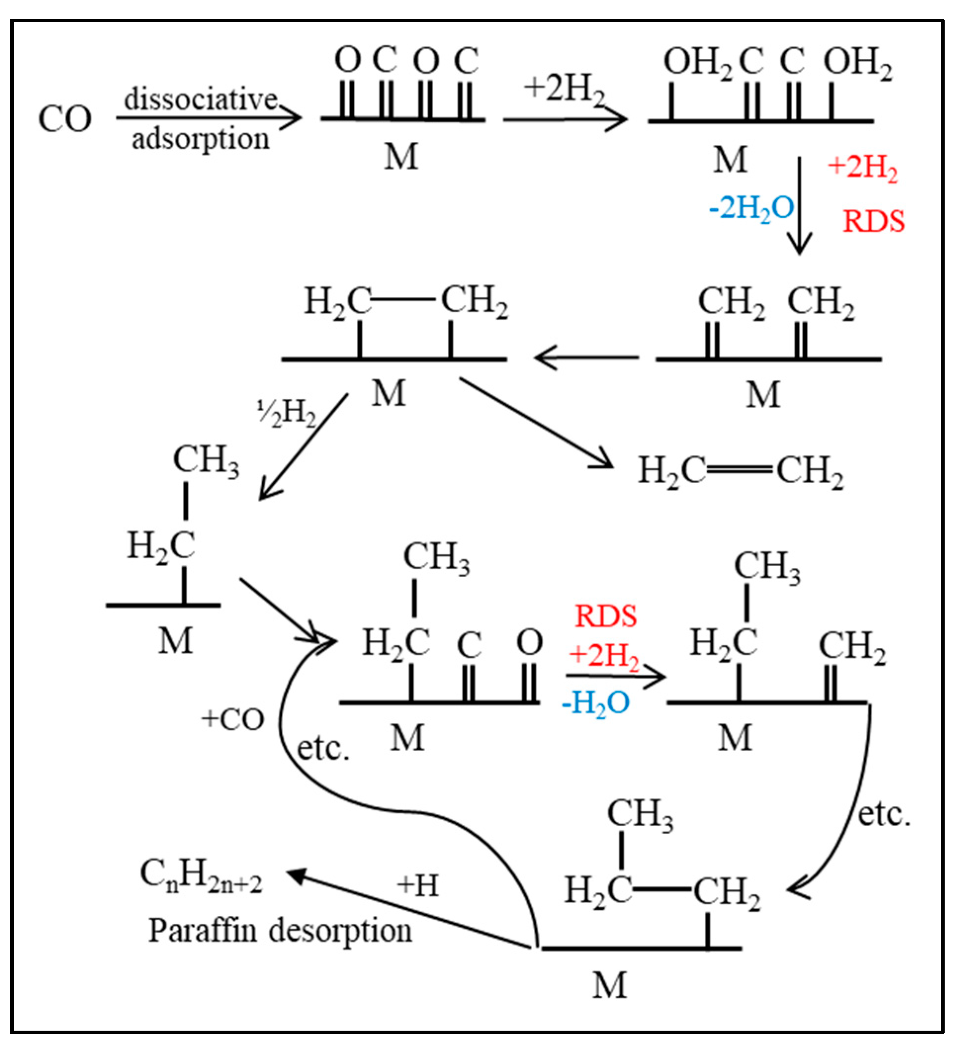
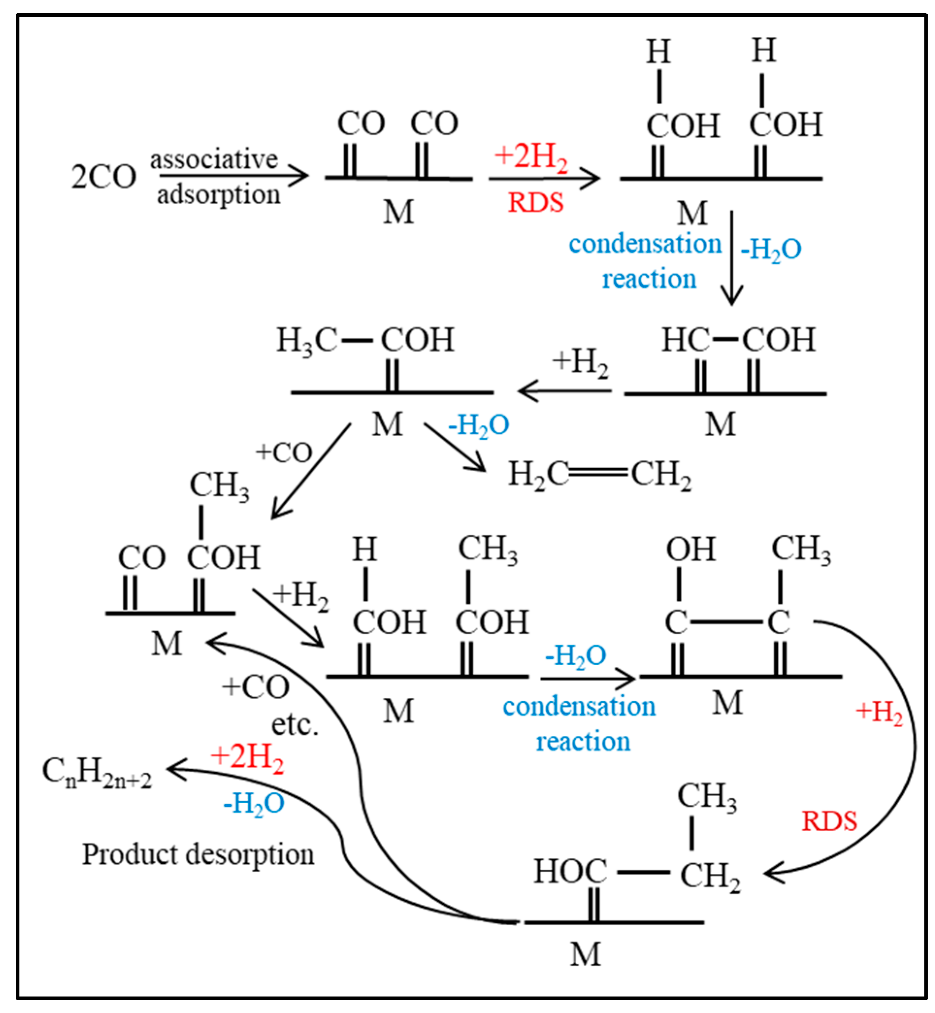
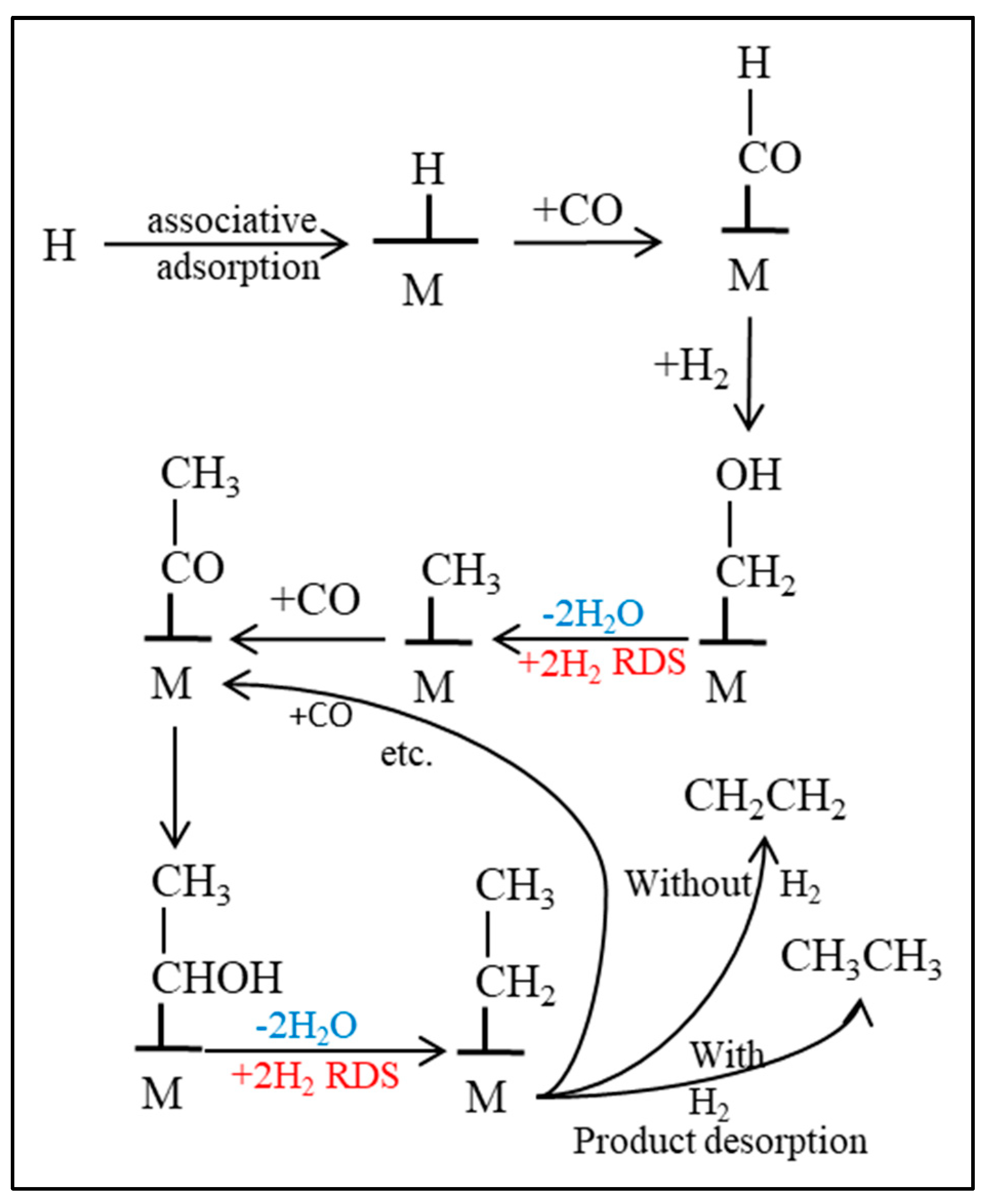
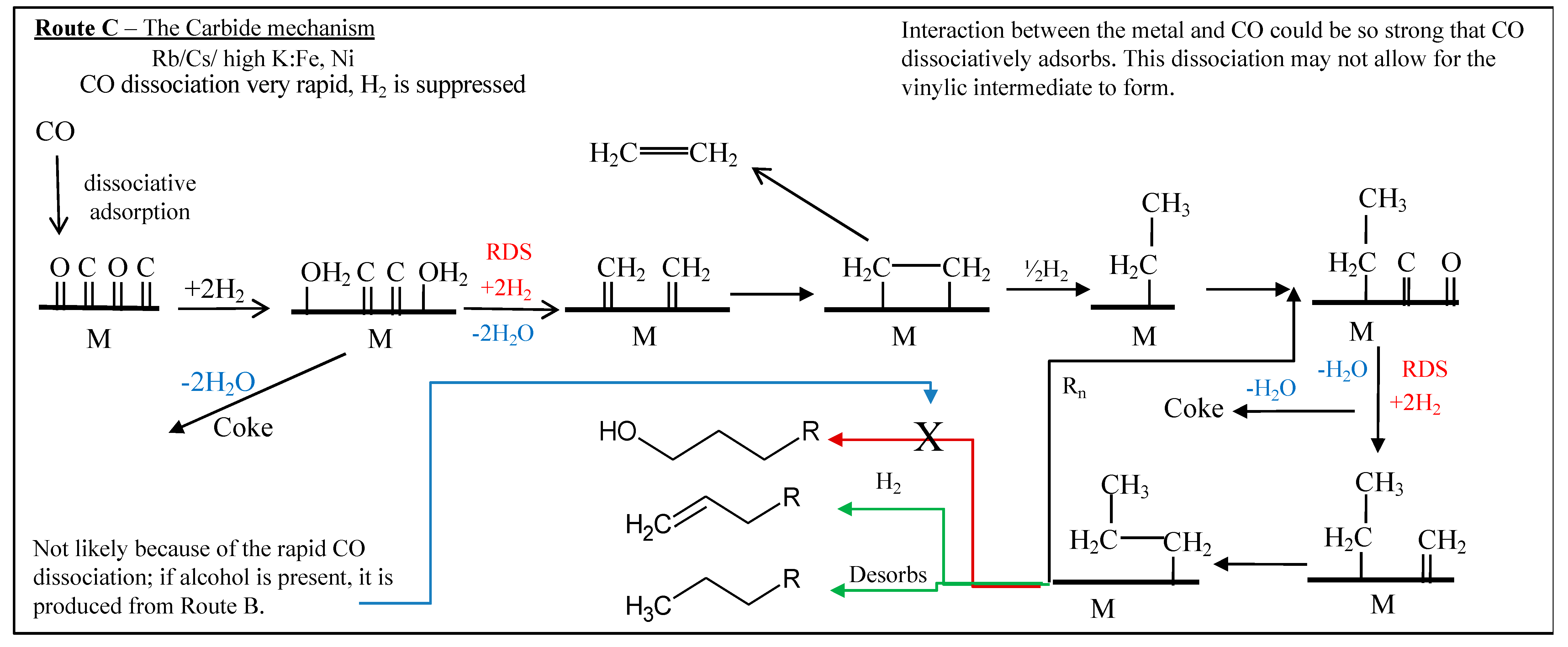
Fischer, discerning that the synthesis route involved the formation of aliphatic carbon-hydrogen bonds and knowing the tendency of iron to form iron carbide, proposed a carbide mechanism, as shown in Figure 3. Although Fischer promoted this mechanism, it was not his first choice; he did not favor the carbide mechanism until results displayed hydrocarbons as the primary products for FTS [44]. Although this mechanism was set aside for a brief period, recent advances in surface science revealed that the catalysts displayed a high surface coverage of carbon, with little surface oxygen, and revived the idea that hydrocarbon products could be synthesized through the combination of methylene groups [45,46,47,48,49]. In the carbide mechanism, CO dissociatively adsorbs on the active FTS metal, covering the surface with carbon and oxygen atoms. The adatoms are sequentially hydrogenated, forming water and methylene monomer. Previous work that was done by Ojeda et al. discusses the quasi-equilibrium assumption for the dissociation and hydrogenation of CO within the first hydrogenation step; the second step is assumed to be rate-limiting [50]. Fischer first proposed a mechanistic route involving oxygenate intermediates for FTS, as very little aliphatic material was generated, and the products were mostly comprised of alcohols. Although the carbide mechanism gained ground after being proposed by Fischer, work that was conducted by Kummer and Emmett [46,47] once again gave rise to an oxygenate mechanism [49]. The detailed example within Figure 4 is currently known as the enol mechanism.
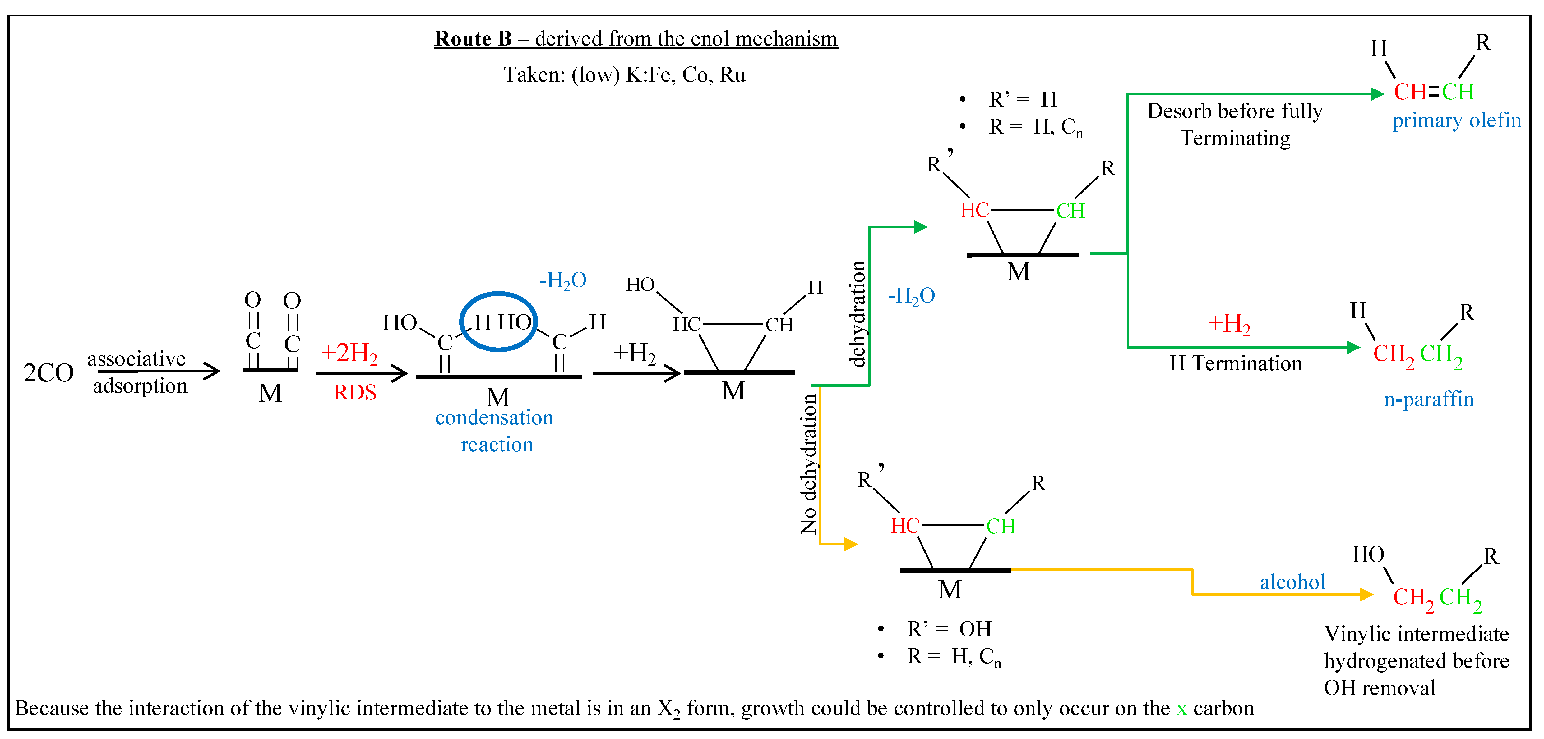
The enol mechanism describes CO adsorbing without dissociation upon the FTS active metal surface. After chemisorption, CO reacts with adsorbed H atoms to create hydroxymethylene (M-CHOH). The enol structure grows by a sequence of condensation steps using the hydroxyl groups of adjacent hydroxymethylene species. This mechanism describes a route where the rate-controlling step is the hydrogenation of adsorbed CO.
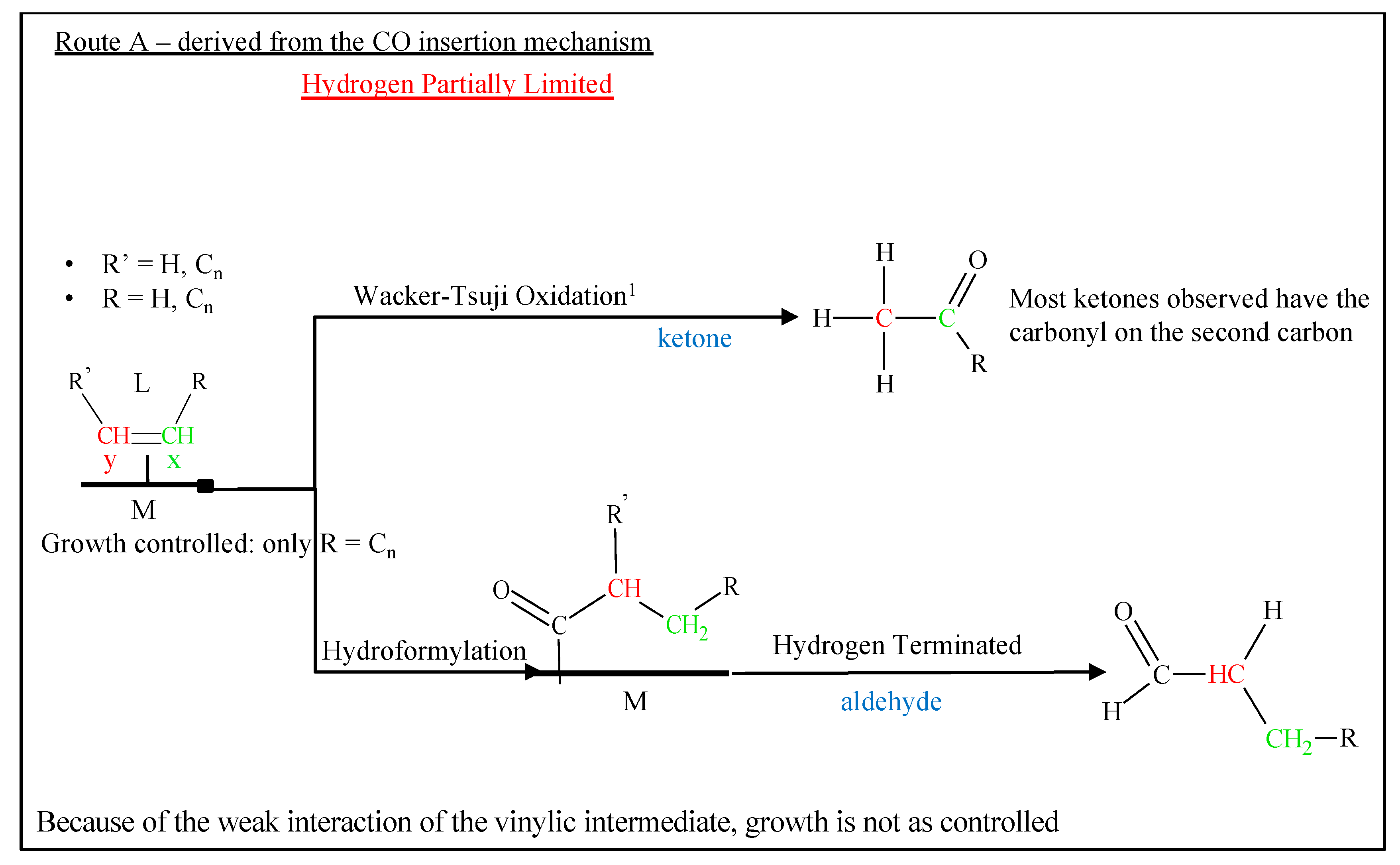
Another commonly proposed mechanism is CO insertion [50], which is displayed in Figure 5, where the CO is molecularly adsorbed onto the active catalyst, and it undergoes bond scission only after being incorporated into the chain. Again, the proposed rate-limiting step is the hydrogenation of CO to the CH2 methylene group. The assumed monomer for this mechanism is simply CO through its insertion into metal-carbon bonds. Interestingly, CO insertion is a common step in homogenously catalyzed reactions, such as hydroformylation [51]. The mechanism continued to be scrutinized, and even the primary versus secondary products are still subject to debate; several research groups are focused on shedding light on this topic [52,53,54].

1.6. Anderson, Schulz, and Flory

A polymerization model, as independently developed by Anderson et al. [55], Schulz [56], and Flory [57], which is known as the Anderson-Schulz-Flory (ASF) model, can describe the range of hydrocarbon products that were synthesized by FTS. The ideal FTS distribution is expressed by Equation (1), where the ASF model is the most commonly used to date:
M n n = ( 1 α ) 2   α n 1  
where Mn/n is the mole fraction of a hydrocarbon with carbon number n, and α is defined as the chain growth probability. Equation (2), which describes alpha (α), is defined by the molar rate at which the chain propagates (rp) versus the rate at which it terminates (rt).
α   =   r p ( r p +   r t )
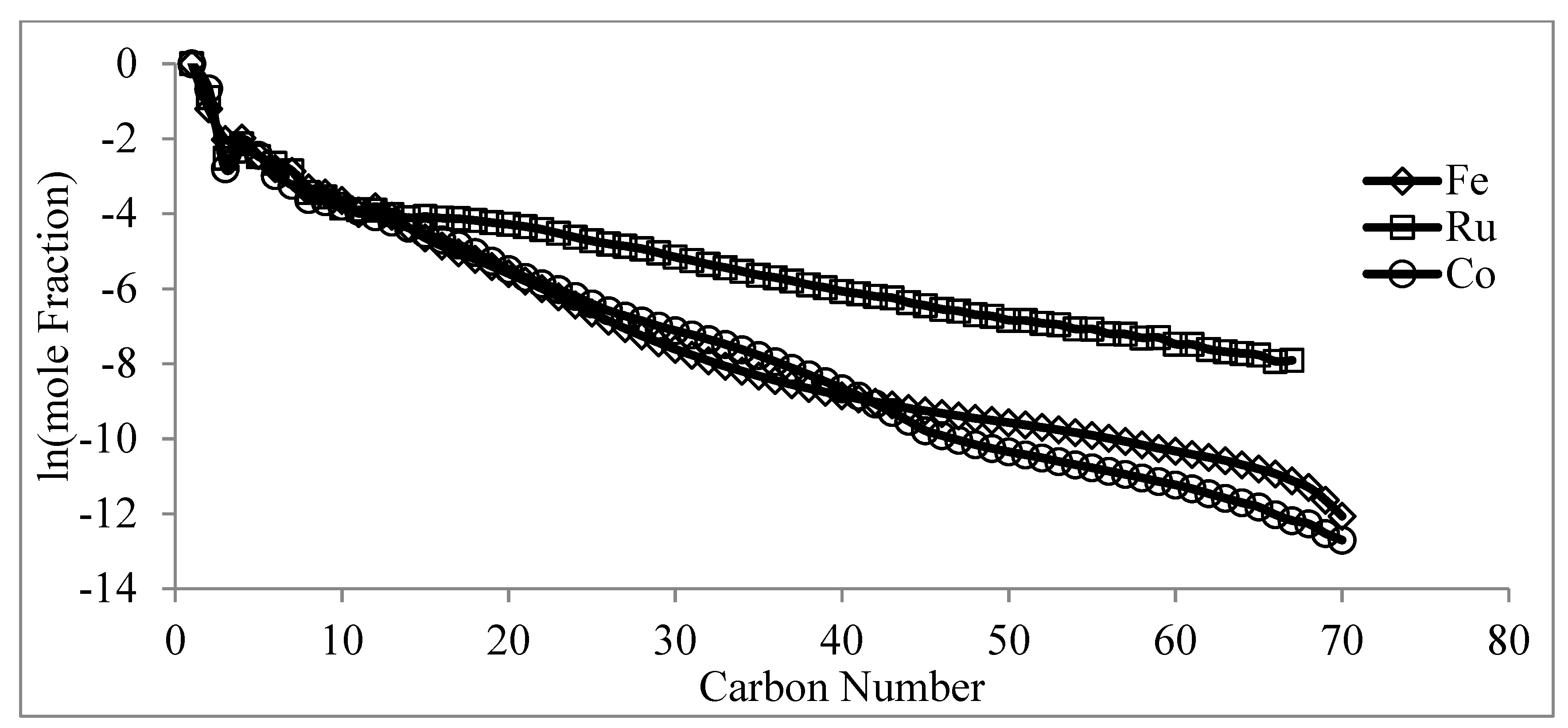
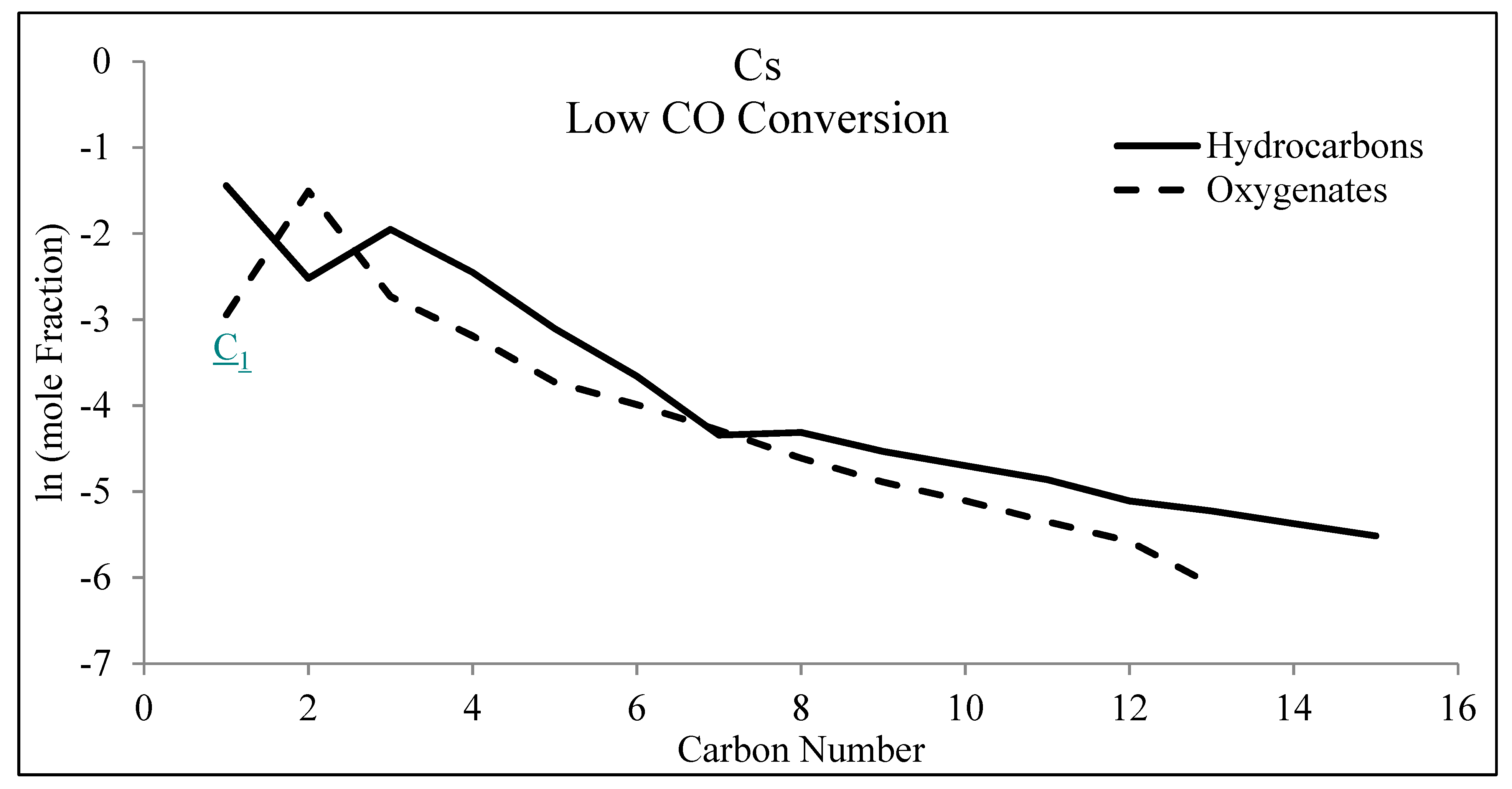
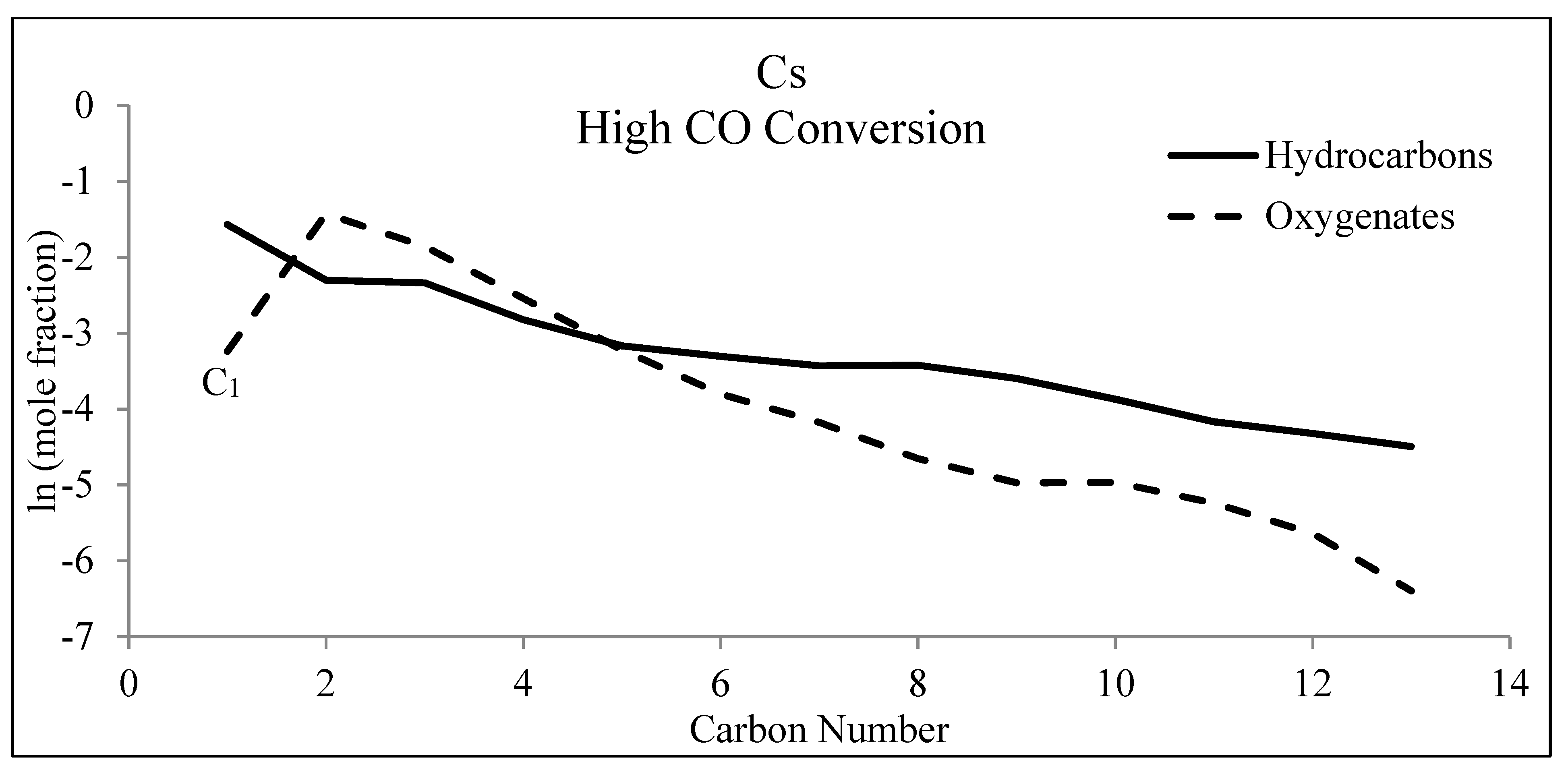
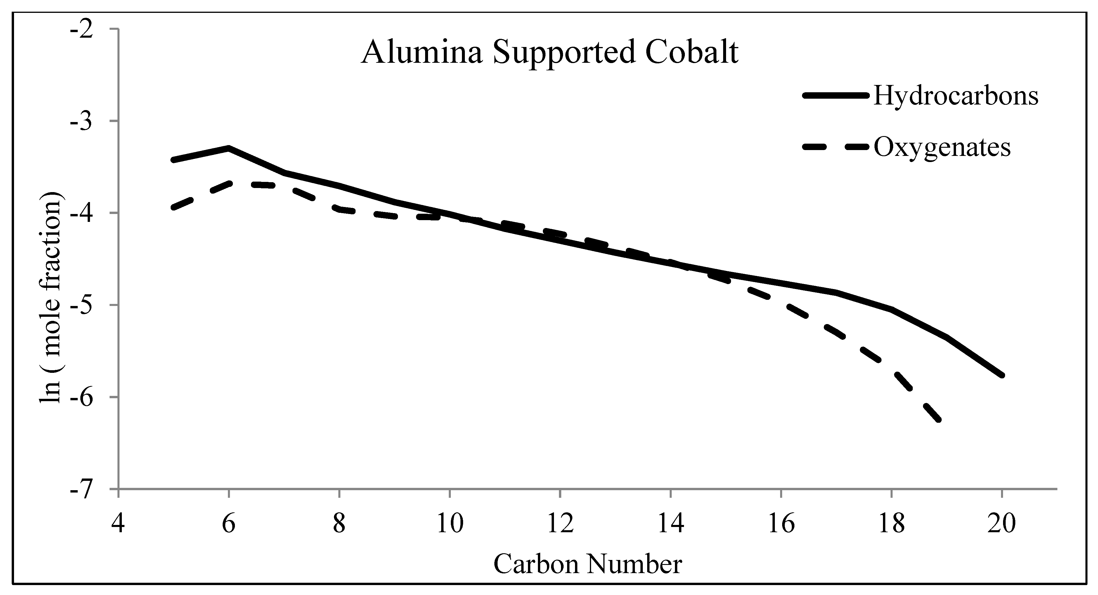
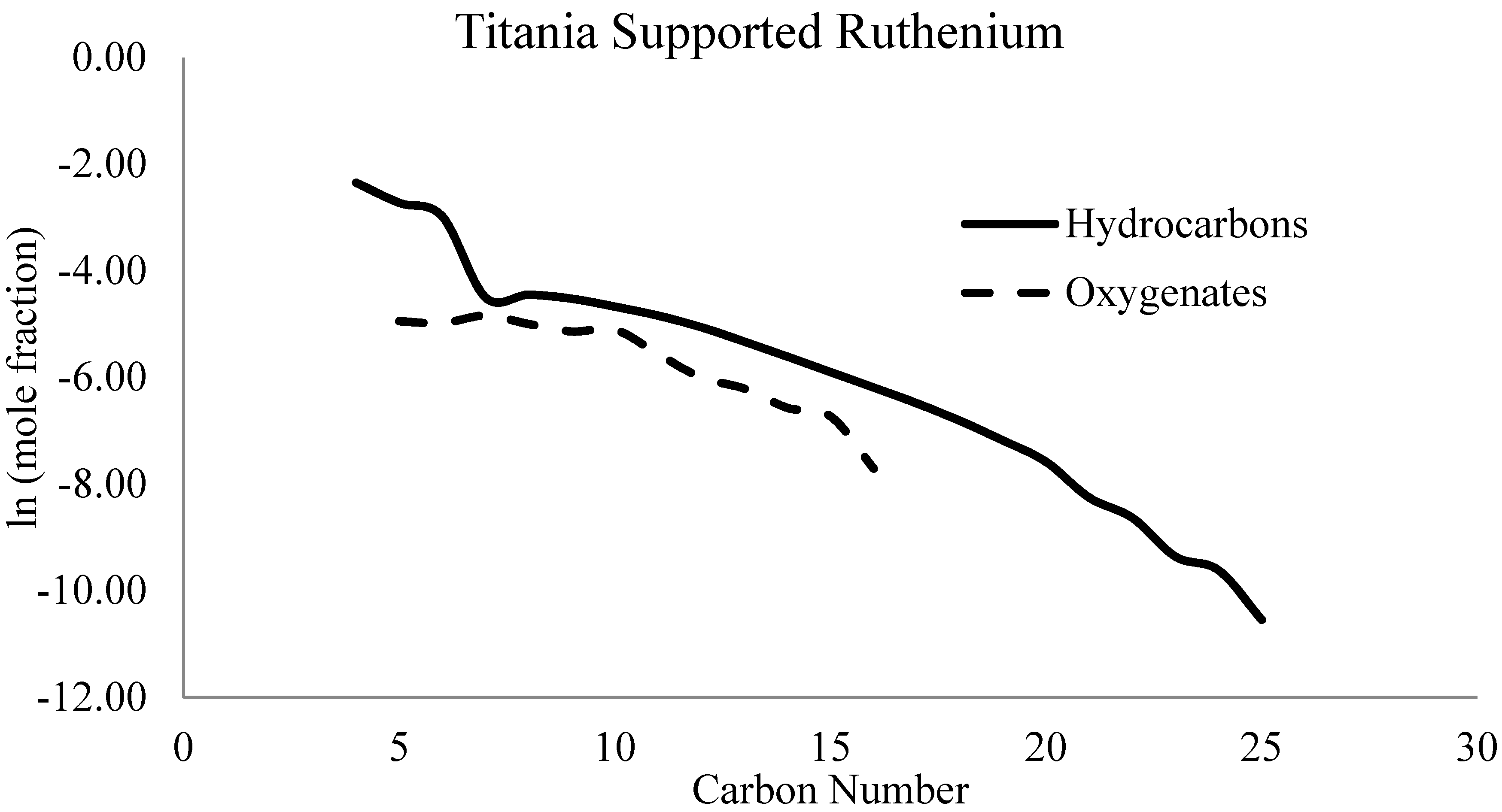
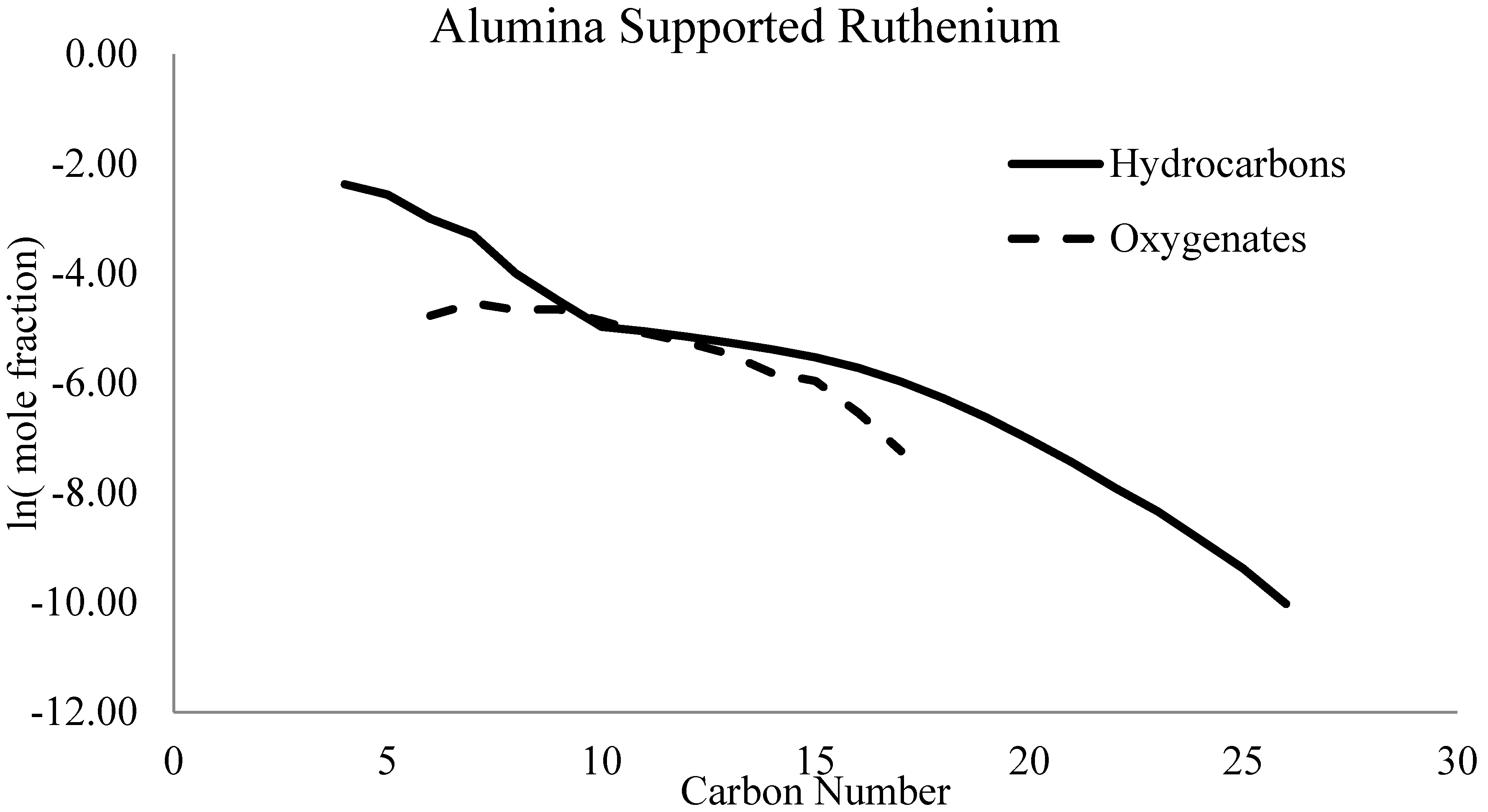
The ASF polymerization model assumes that the hydrocarbon chain lengths are independent, and thus, solely dependent on rp and rt. The distribution of FTS products can then be plotted in a linear manner with the natural log of the mole fraction as the dependent variable, y, and the carbon number as the independent variable, x, as shown in Figure 6 for iron, cobalt, and ruthenium catalysts.
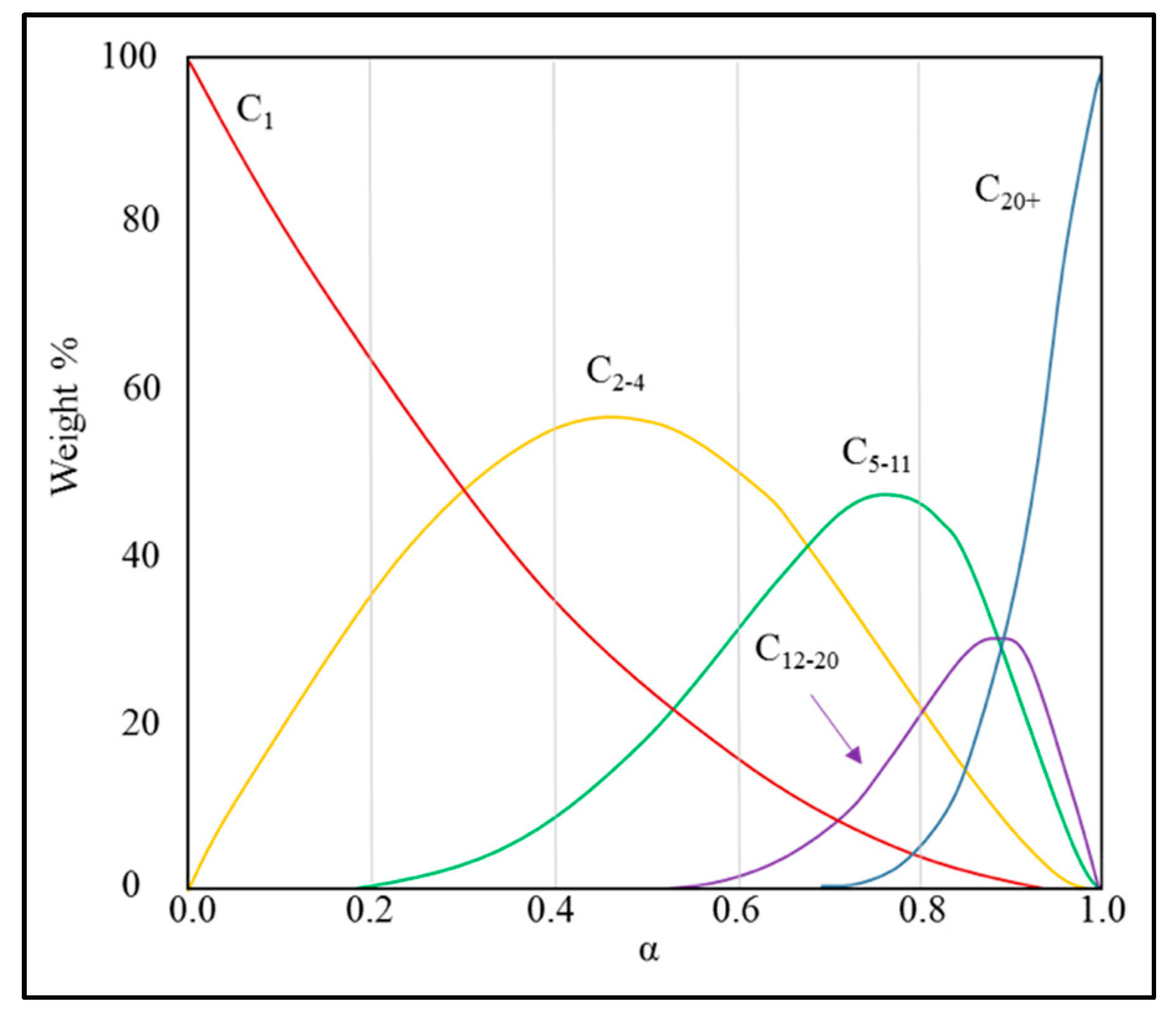
The ASF polymerization model is useful as a tool to describe a range of hydrocarbons when assessing a series of catalysts that portray certain characteristics. More importantly, trends can be displayed that attempt to understand the promoter, support, and reactor effects on FTS based on deviations from the ASF model. Figure 7 provides a general picture of an expected distribution for specific α values. A typical ASF plot totals all products (i.e., 1-olefin, n-paraffin, cis/trans-2-olefin, alcohol) to directly relate CO to a carbon number (i.e., C10, C11, etc.) and not to a specific product type. However, this review examines the types of products separately to compare the ASF model for more than one product classification. The products that are present in the oil and wax phases are so numerous that the retention times from standards could not be used to identify all of the products. Therefore, peaks for oxygenated compounds in the oil and wax are separated and identified using gas chromatography-mass spectrometry (GC-MS). Oxygenates in the gas and water samples are identified based on the retention times of standards. The ASF model is useful in describing the distributions of the different classifications of hydrocarbons and oxygenates. The apparent chain growth probability factor (i.e., α), as defined by the ASF model, depends on several factors, including vapor-liquid equilibrium (VLE), type of reactor, diffusional limitations, olefin re-adsorption, etc. [21,58,59,60,61,62,63,64,65,66,67,68,69,70,71,72]. Oxygenated compounds vaporize at higher temperatures (when compared at similar carbon chain length) and therefore will be more severely affected than hydrocarbons [73]. Oxygenates seem to display a negative deviation in ASF plots at approximately C12, as opposed to hydrocarbons, and this is likely due to their higher boiling point in comparison with hydrocarbons of the same length.

1.7. Product Distribution of Fischer–Tropsch Synthesis

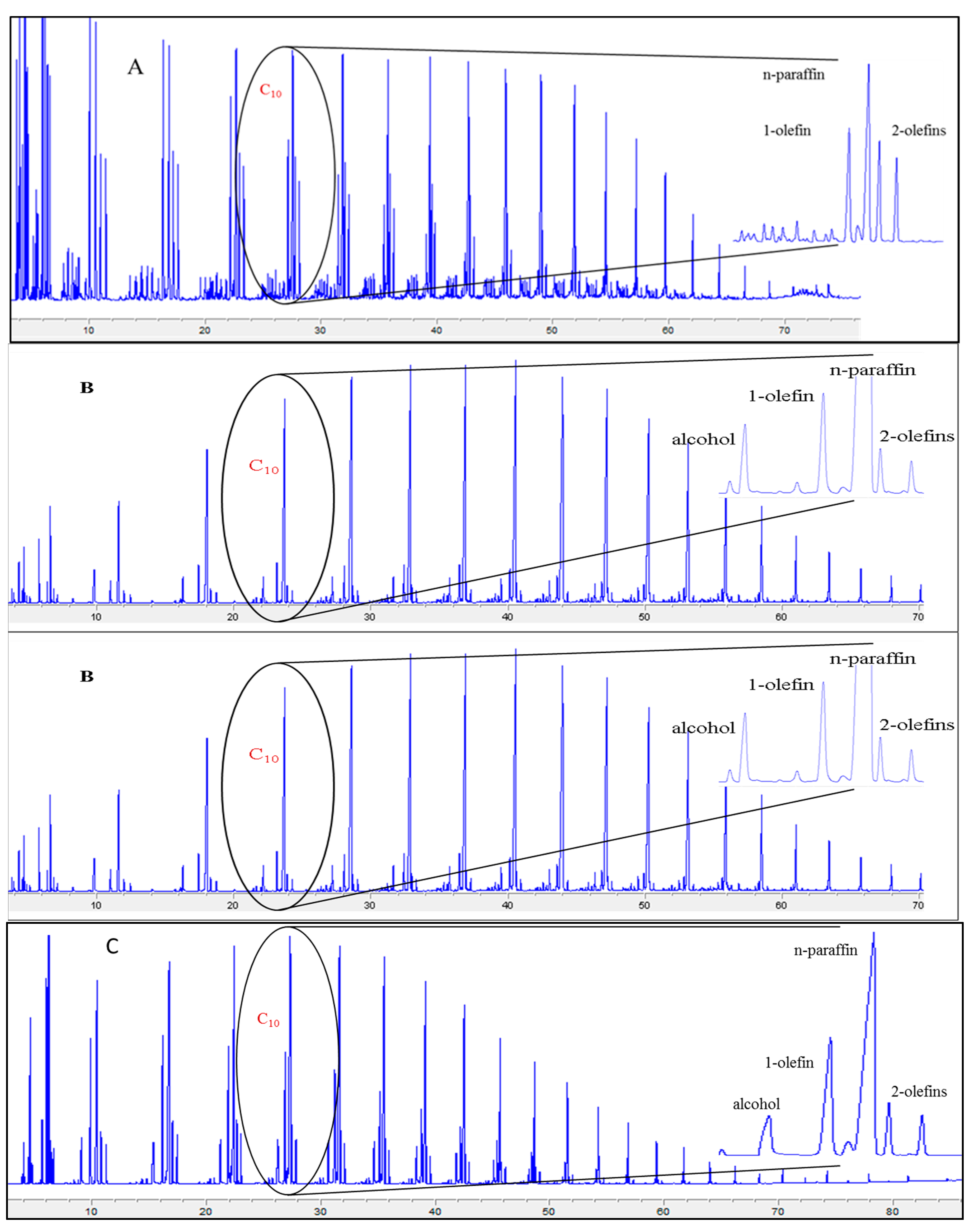
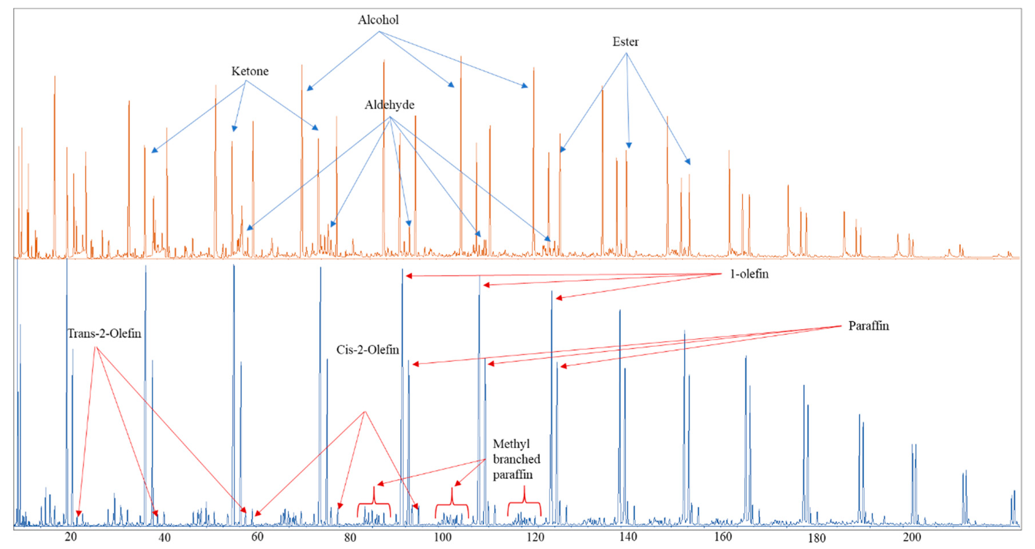
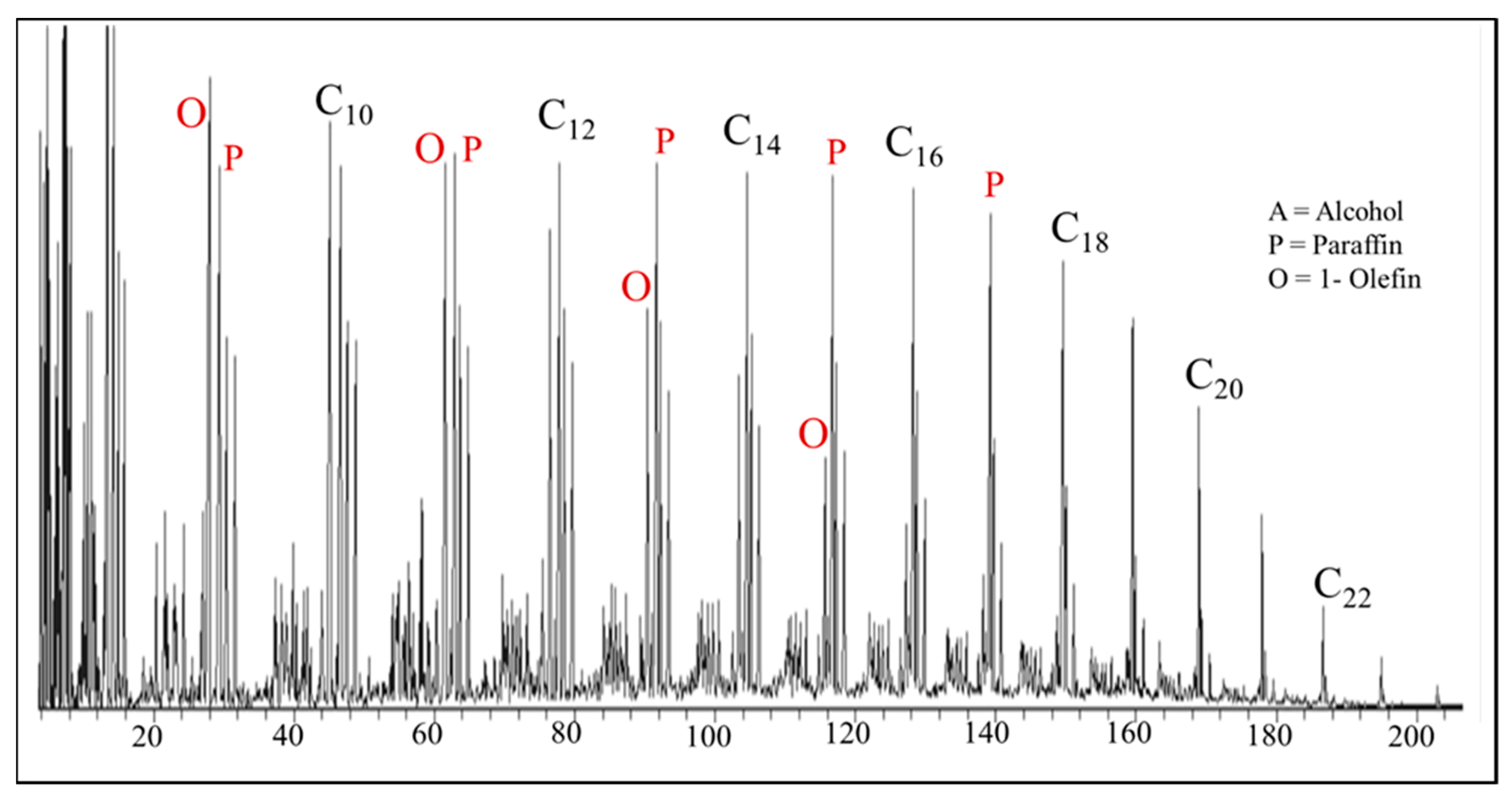
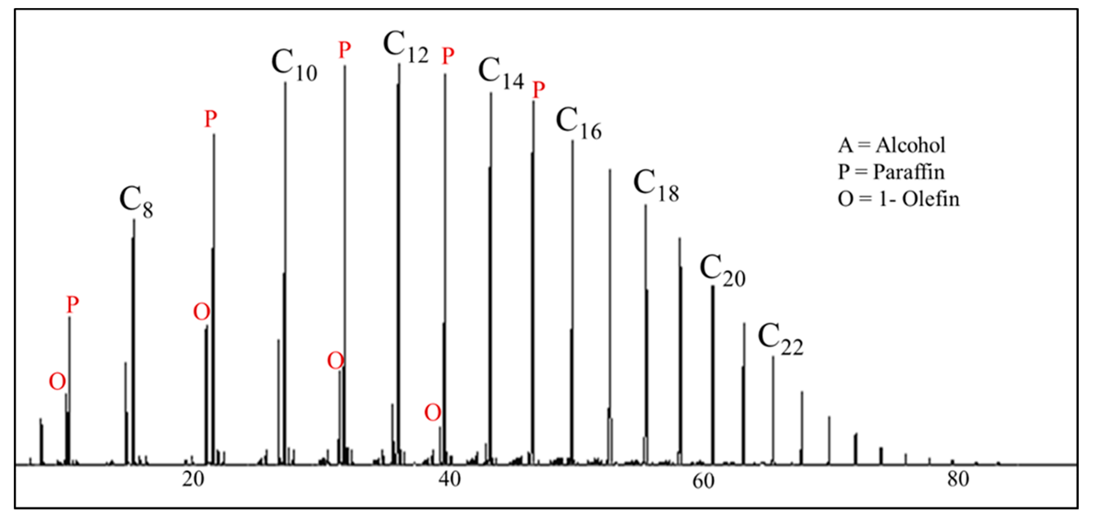
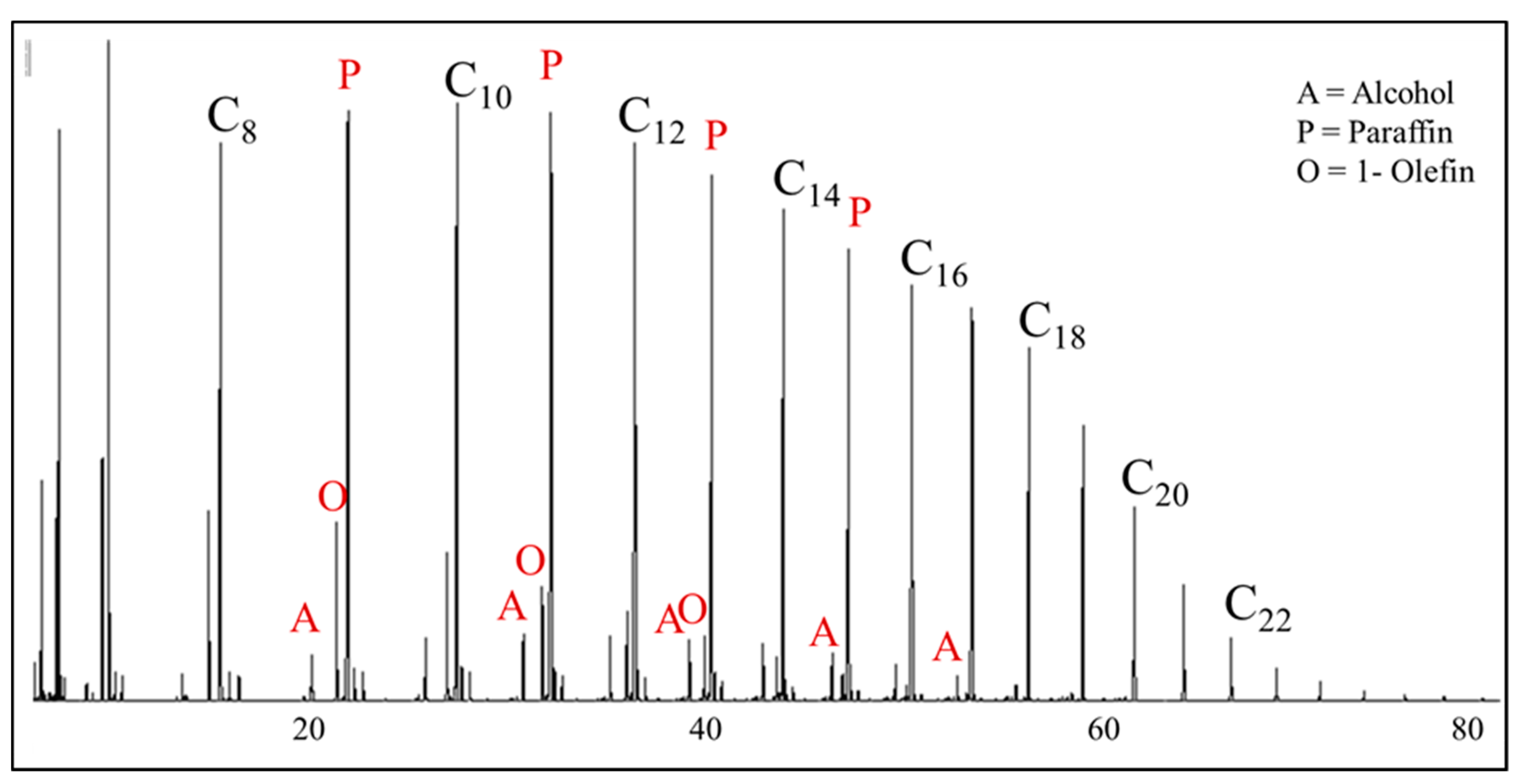
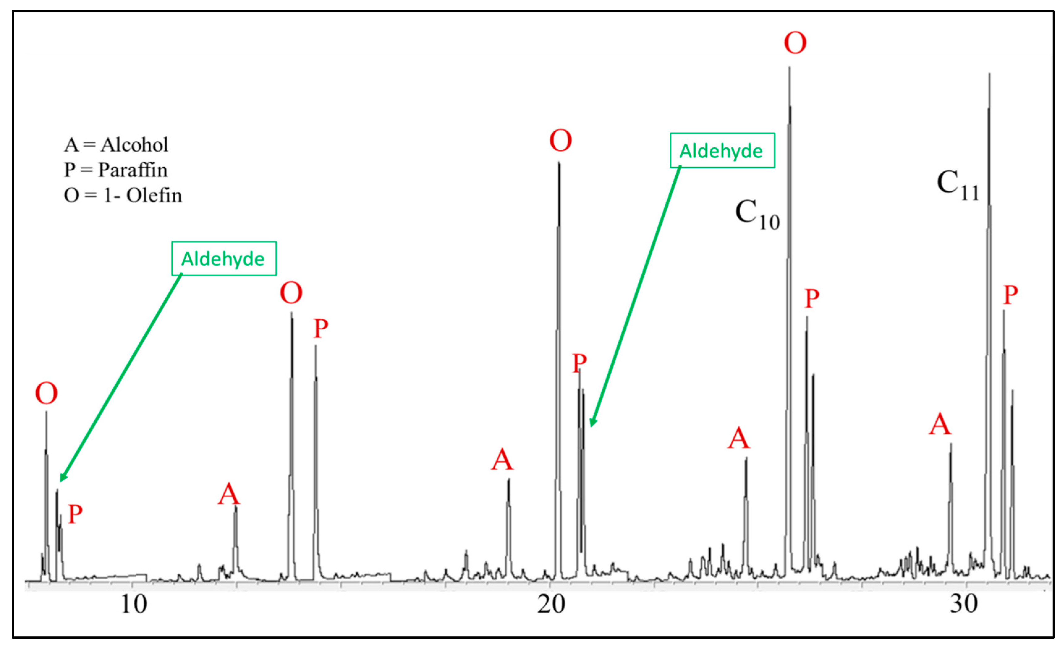
The four primary classifications of FTS hydrocarbon products are: 1-olefins, paraffins, trans-2-olefins, and cis-2-olefins. To give an idea of the vast array of products, Figure 8 displays chromatograms of merely the oil phase (excluding gas, aqueous, and wax phases) for the distribution of products for iron (A) cobalt (B), and ruthenium (C) catalysts. General examples of a flame ionization detector (FID) scan (Figure 8) displays weight fractions of each major component, which can significantly vary, depending on the active metal. The effect of chain length on selectivity depends on the process conditions (e.g., temperature, pressure, H2/CO ratio) and the type of reactor (e.g., slurry or fixed-bed). Chain length affects the olefin/paraffin (O/P) ratio [74,75,76,77,78,79,80,81] through differences in re-adsorption that, in turn, affect secondary reactions, such as hydrogenation, isomerization, and the re-initiation of chain growth [76,80,81]. Hydrocarbon chain length also influences the olefin/paraffin ratio by the disproportional accumulation of heavier products due to the decreasing vapor pressure with increasing chain length, particularly in slurry-based FTS systems [77,82]. As residence time increases, re-adsorption increases in a proportional manner; thus, an inverse relationship arises where, the longer the hydrocarbon chain, the lower the O/P ratio (as n increases, O/P decreases). Figure 8 visually describes this attribute (in this case using an iron catalyst), where the olefinic component more rapidly decreases with the carbon number in the FID chromatograph.
An advantage of the FID, specifically described later, is the ability to relatively assess peaks across chromatograms for different catalysts by weight %. This cannot be used to compare the total products produced, but the percentage of a specific product to the total. Here, this comparison works to quickly evaluate if a catalyst produces higher amounts of 1-olefin per carbon number. When calculating the actual mole of carbon %, the numbers agree with this relative amount per product, allowing the FID chromatogram to provide a quick “fingerprint” of product selectivity per catalyst.
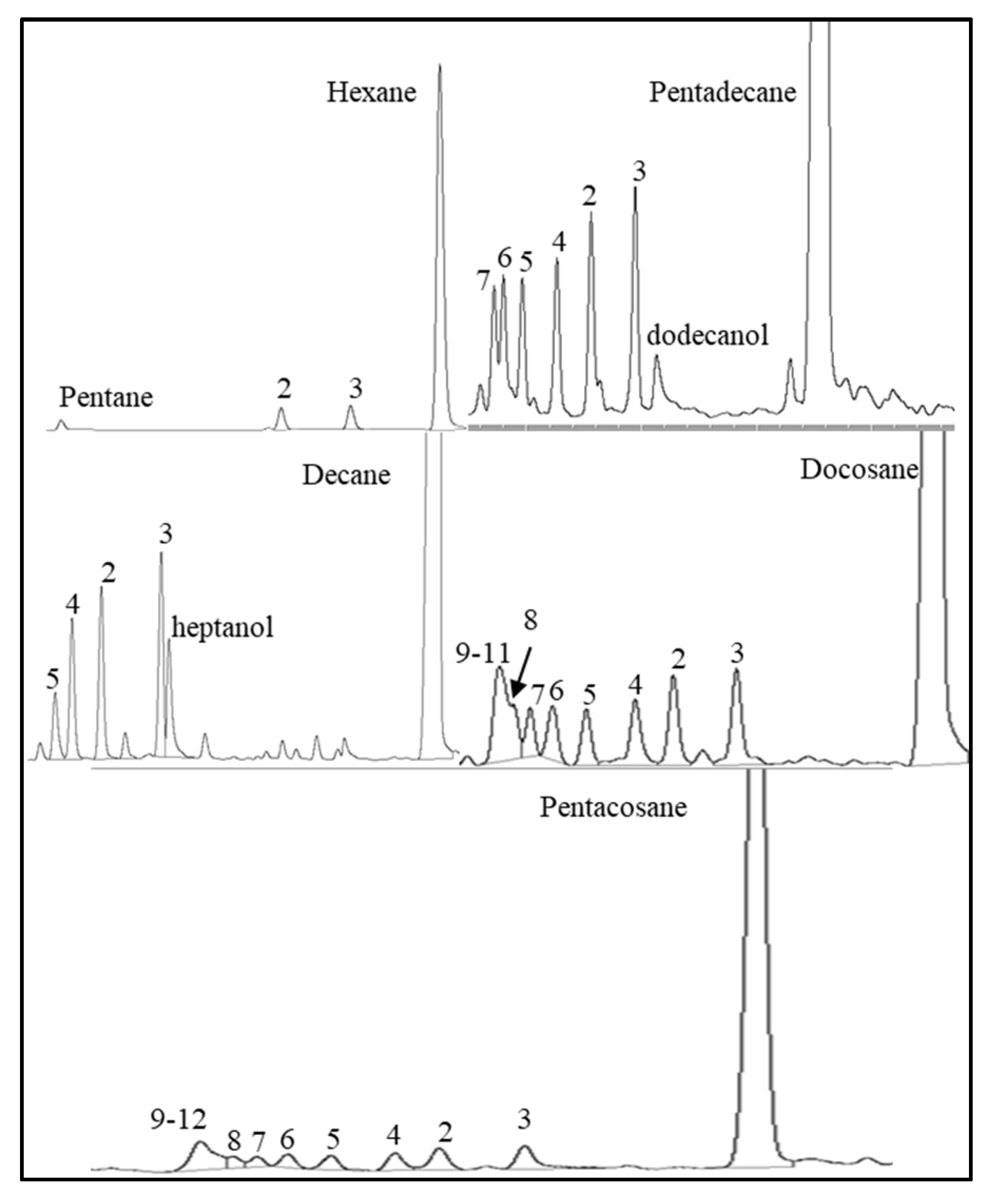
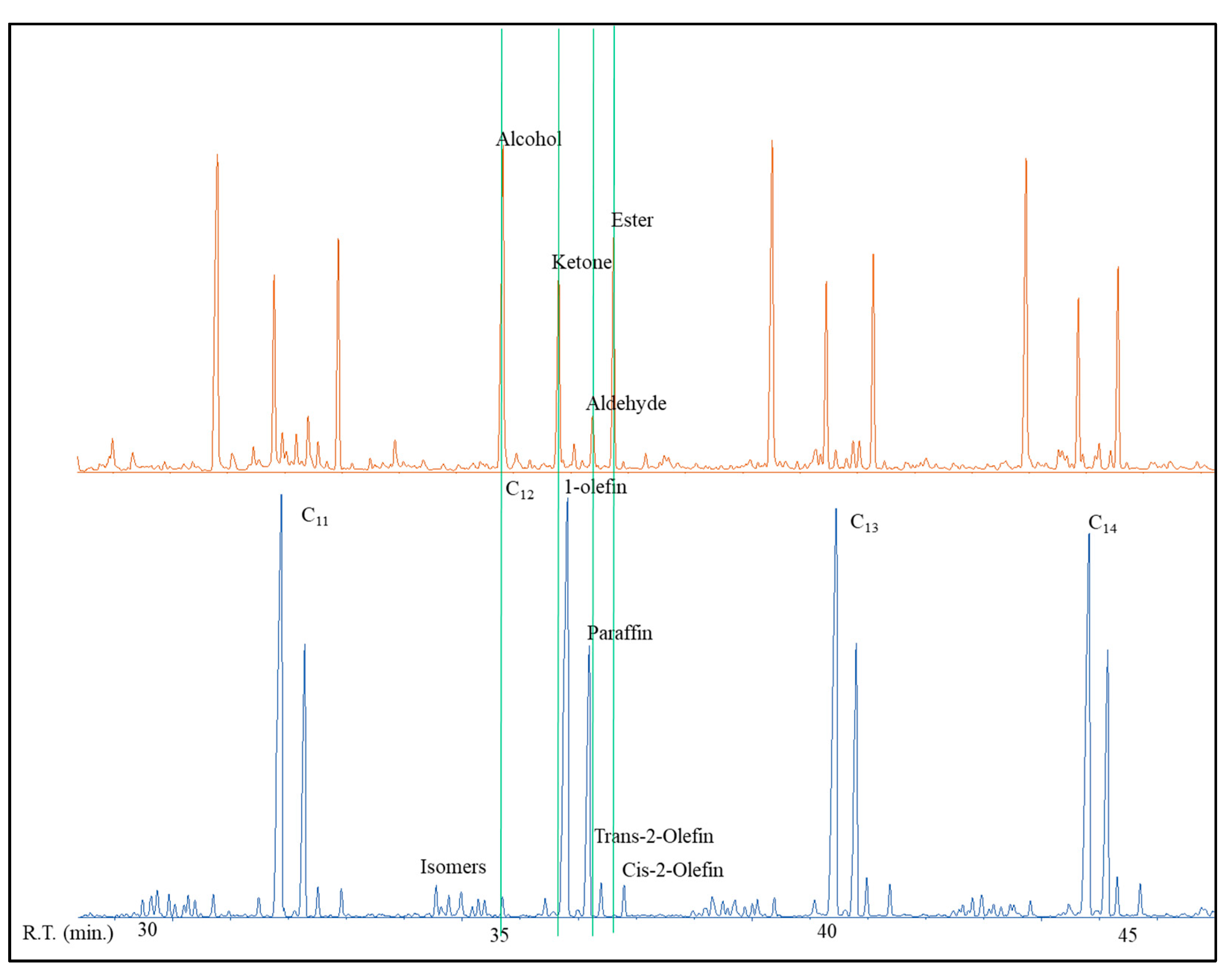
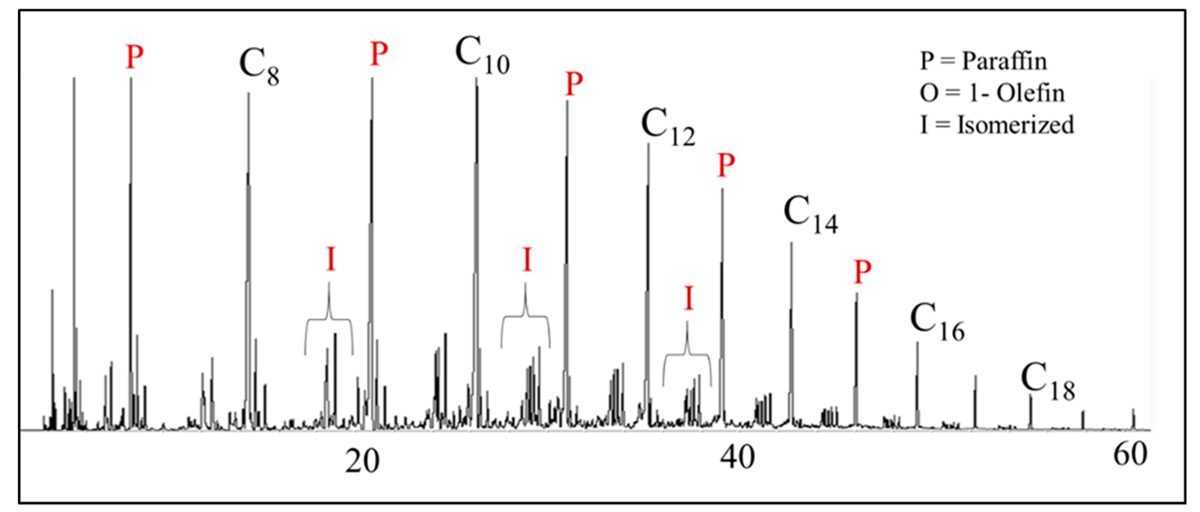
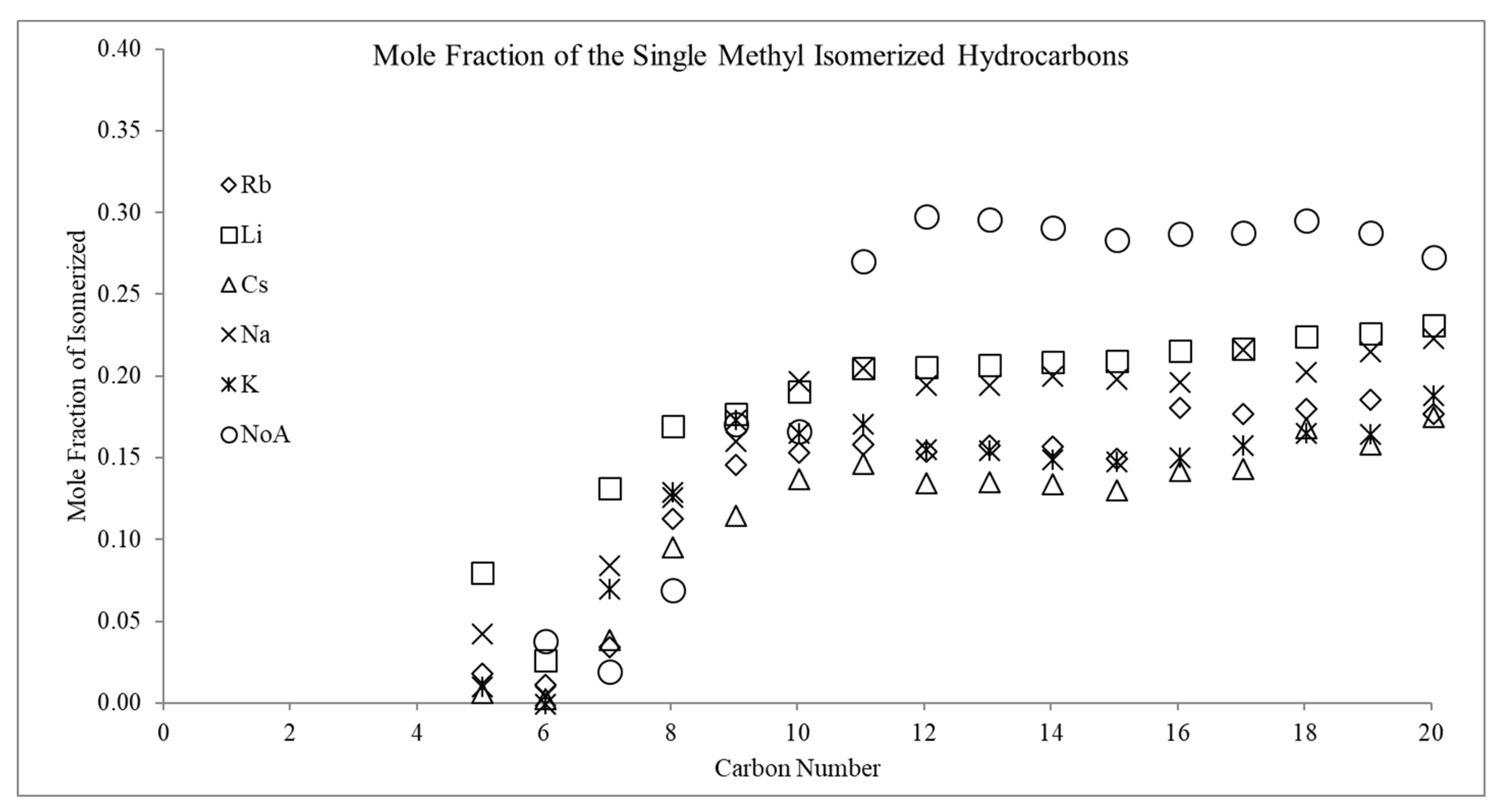
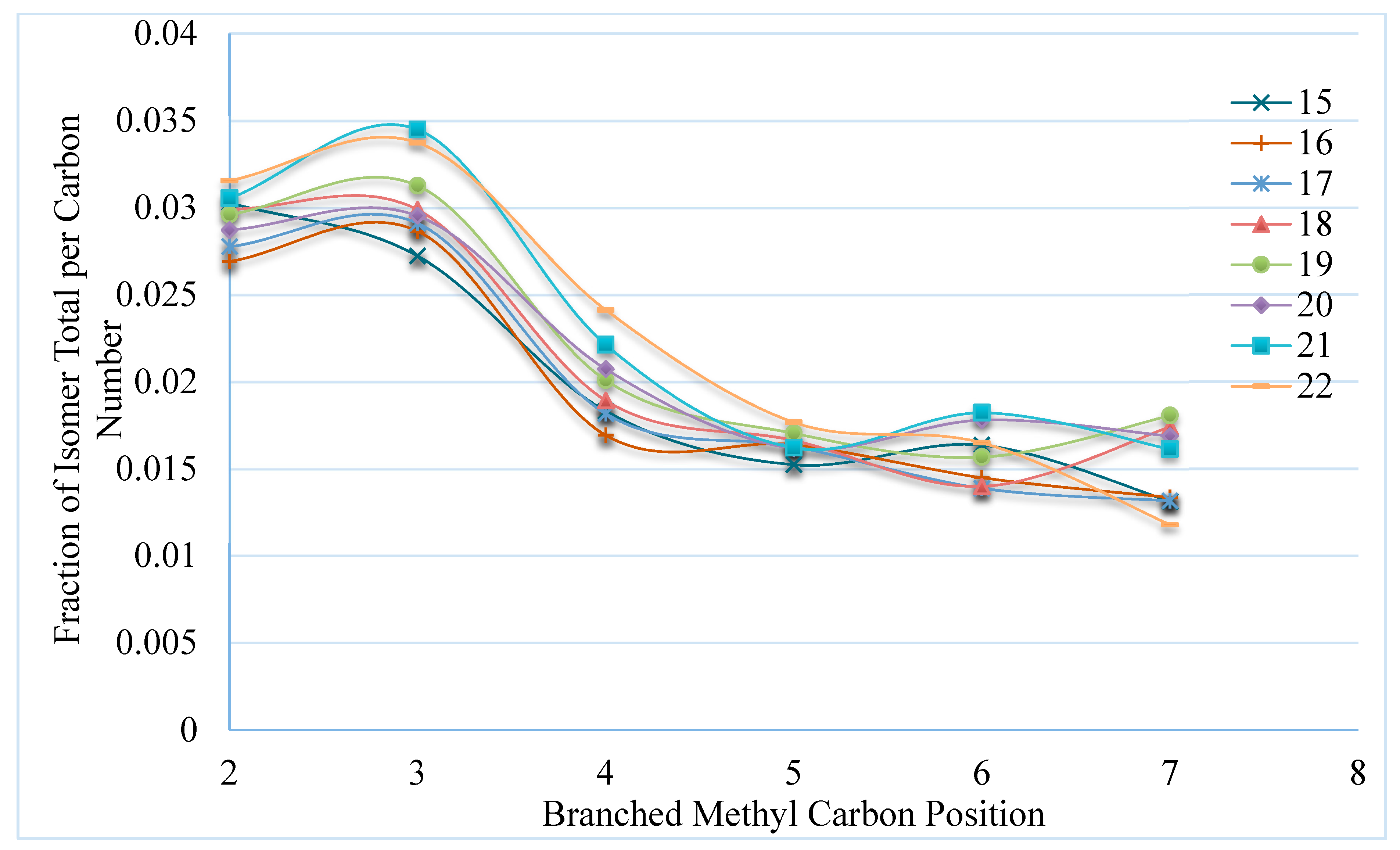
The isomerized materials, although minor, can be observed from the gas range up to the longer chains in the oil fraction. Most of the branching that occurs in FTS is single methyl branched material, as shown in Figure 9 and Figure 10. The diversity of these materials depend on the specific carbon number and, as the carbon number increases, the more diverse the methyl-branched paraffin become.
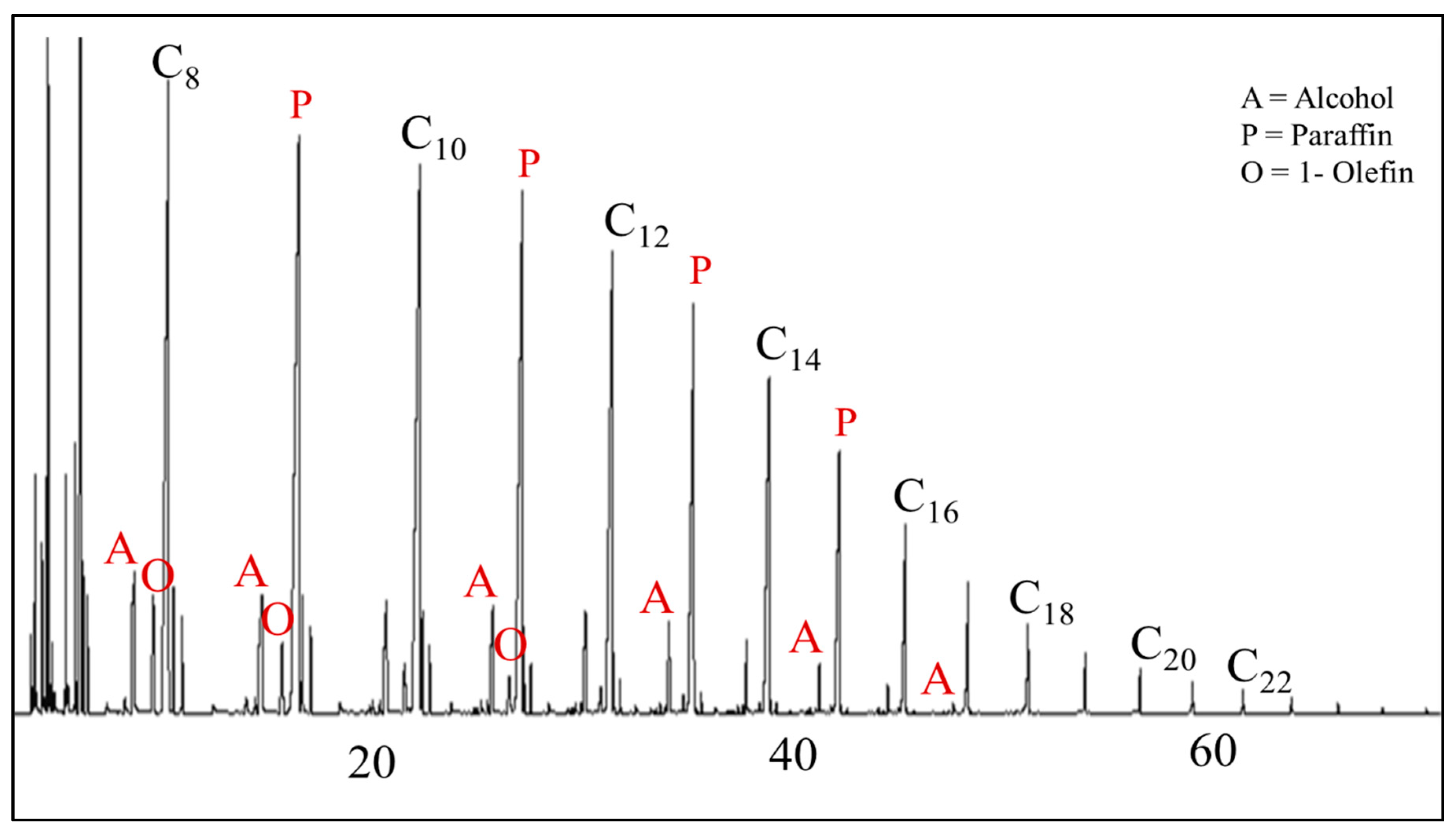
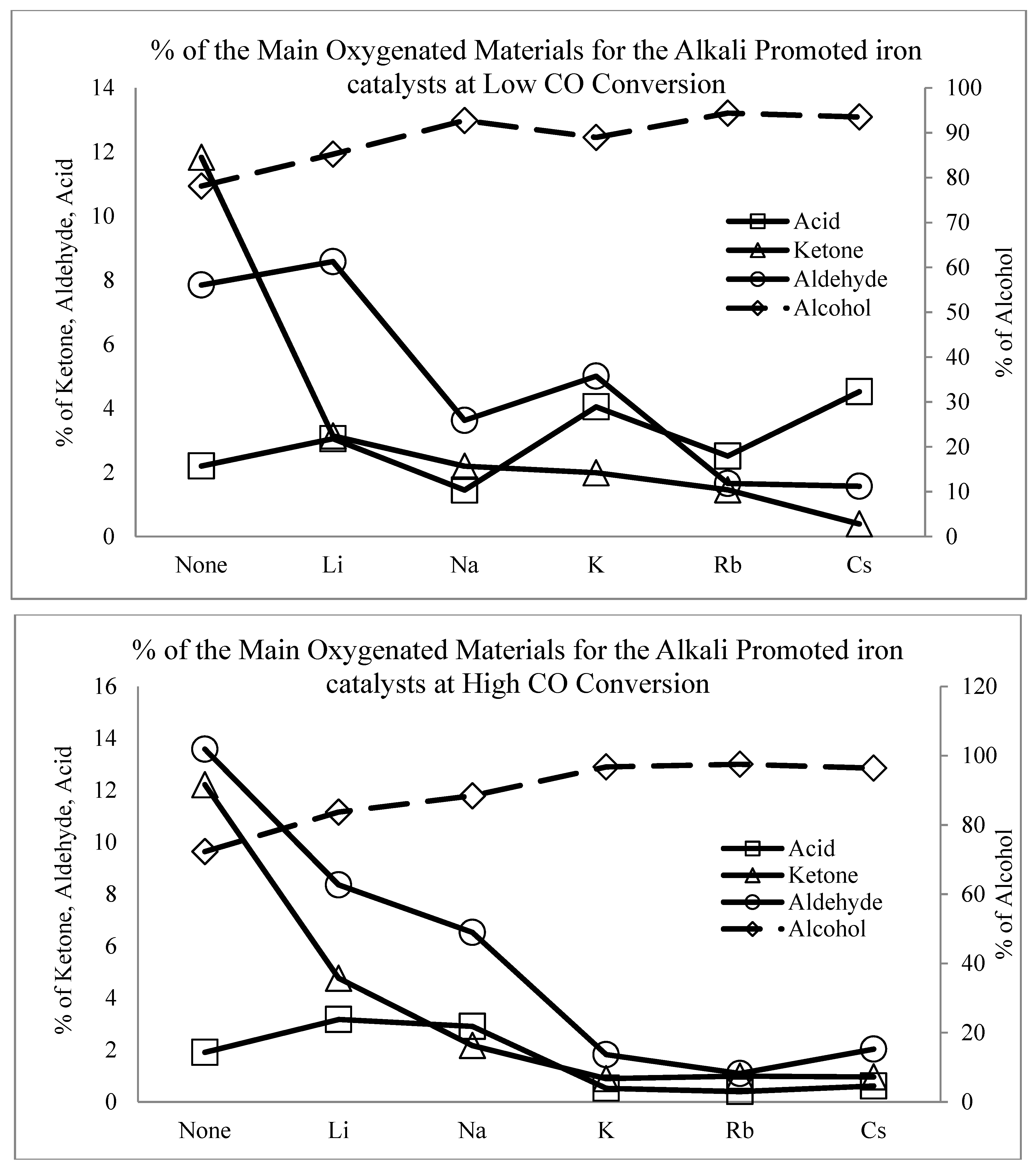
A minor fraction of the distribution, which consists of oxygenated products (Figure 11 and Figure 12), is also important. For example, oxygenates can be used to investigate the mechanism of FTS [46,47,82] or serve as alternative chemicals. FTS catalysts have been altered in a specific manner with the intent of increasing the selectivity to oxygenates with the aim of producing alternative chemicals (e.g., chemical feedstocks) [40,41,42,83,84]. Two variables that affect product distribution [44] and that were controlled by changing catalyst formulation, include metal (e.g., alkali) promoters for iron, and support type (as well as the interfacial contact between support and metal) for supported cobalt and ruthenium catalysts.
The aim of this manuscript is to shed light on how product selectivity varies with FTS catalyst type for low-temperature FTS and, in turn, gain greater insight into the FTS mechanism.

2. Experimental

2.1. Catalyst Synthesis

2.1.1. Iron Catalysts

Fe–alkali/SiO2 catalyst preparation: The preparation of a precipitated iron-silica catalyst with an atomic ratio 100Fe/4.6Si has been described elsewhere [85]. The alkali (Li, Na, K, Rb, and Cs) was then added by incipient wetness impregnation (IWI) with aqueous alkali carbonate to obtain an alkali/iron atomic ratio of 1.44/100 and copper, a known promoter, was not added in order to avoid complicating the analysis [85].
K/silica/Cu and K series iron catalysts: The preparation of the precipitated iron catalyst series was performed by dissolving iron (III) nitrate nonahydrate in deionized water, followed by the addition of tetraethylorthosilicate (TEOS) to achieve the desired Fe:Si ratio. This mixture was vigorously agitated until the TEOS had hydrolyzed. To make the final Fe:Si base, the slurry was then added to a continuously stirred tank reactor (CSTR), which served as a precipitation vessel, followed by a stream of ammonium hydroxide (14.8 M) that was added to maintain a pH of 9.0. Next, the iron base catalyst was vacuum filtered and then washed twice with deionized water. The final filter cake was dried for 24 h in an oven at 110 °C with flowing air. Lastly, the Fe:Si catalyst base powder was then impregnated by incipient wetness with specific amounts of aqueous potassium nitrate and copper nitrate solutions in order to produce the desired atomic compositions (0.5K:100Fe; 1K:100Fe, 1.25K:5.1Si:100Fe, 1.25K:2Cu:5.1Si:100Fe, 1.25K:5Cu:5.1Si:100Fe, 2K:100Fe, 5K:100Fe, 5K:5.1Si:100Fe). Finally, the Fe:Si:K:Cu catalysts were dried at 110 °C overnight, followed by impregnation, drying, and calcination in a muffle furnace at 350 °C for 4 h.
Fe-Cu/MnO2 catalyst preparation: Manganese sulfate solution (1.7 M) was slowly added to the 0.4 M potassium permanganate solution, and after deposition, nitric acid (0.6 M) was added to this solution. This precipitate was aged for 10 h at room temperature, after which it was washed with deionized water and then dried at 120 °C for 15 h. Finally, the MnO2 support was obtained after calcination at 200 °C for 4 h. The MnO2 supported Fe-Cu catalysts were prepared by the IWI method using an aqueous solution of iron and copper nitrates. The iron loading of the catalyst was 20% and the Fe/Cu molar ratio was 100:15. After impregnation, the catalysts were dried at 120 °C for 15 h and then finally calcined in air at 350 °C for 4 h.

2.1.2. Cobalt Catalysts

Co/Silica—The 12.4 wt % Co/SiO2 catalyst was prepared by the incipient wetness impregnation of a SiO2 support (Davisil 634, pore volume of 0.75 cm3/g, and surface area of 480 m2/g) with a cobalt nitrate solution. Two impregnation steps were used to load the cobalt precursor. Between each step, the catalyst was dried under vacuum in a rotary evaporator at 80–100 °C. After the second impregnation/drying step, the catalyst was calcined in flowing air at 350 °C for 4 h.
Co/Alumina—Condea Vista Catalox high purity γ-alumina (150 m2/g) was used as a support. Cobalt nitrate (Sigma Aldrich, St. Louis, MO, USA) served as the precursor to load 25% by weight cobalt onto the Al2O3 support. In this method, which follows a Sasol patent [86], the ratio of the volume of solution used to the weight of alumina was 1:1, such that approximately 2.5 times the pore volume of solution was used to prepare the loading solution. Two impregnation steps were used to load 12.5% of Co by weight for each step. Between each step, the catalyst was dried under vacuum in a rotary evaporator at 80 °C and the temperature was slowly increased to 100 °C. After the second impregnation/drying step, the catalyst was calcined at 350 °C for 4 h.
Co/Titania—Preparation of this catalyst is detailed in reference [87].
Co/Ceria—Preparation, and properties of these catalysts can be found in references [40,41,42].
Co/Carbon Spheres—Preparation and properties of these catalysts and reaction tests can be found in reference [59].
Unpromoted Co—A bulk cobalt catalyst was prepared while using cobalt nitrate solution as a cobalt precursor. In this method, a 1:1 stoichiometric amount of ammonium carbonate (aqueous solution) to cobalt, was added to an aqueous solution of Co(NO3)2*6H2O (Aldrich, 98%), in order to precipitate out Co as CoCO3. The precipitate was filtered, and the resulting solids were washed with copious amounts of deionized water. The catalyst was then dried overnight at 120 °C and then calcined at 500 °C in air for 5 h.

2.1.3. Ruthenium Catalysts

Three ruthenium catalysts were prepared by IWI using an aqueous solution of ruthenium nitrosyl nitrate (Alfa Aesar, Haverhill, MA, USA). The samples were dried overnight at 120 °C and then calcined under air flow at 350 °C for 4 h. The catalysts included a 1.2 wt % Ru/TiO2 catalyst with Degussa P-25 TiO2 (72% anatase, surface area 45 m2/g, calcined at 400 °C for 6 h), and a 3.0 wt. % Ru/SiO2 catalyst that was prepared using PQ silica CS-2133 (surface area 352 m2/g, which was calcined at 350 °C for 6 h) as the support. 1.0 wt% Ru/Al2O3 catalyst was prepared using Sasol-Catalox alumina (high purity γ-alumina, surface area 140 m2/g, which was calcined at 350 °C for 6 h) as the support.
Ru/NaY—Specifics on the preparation of the NaY ruthenium catalyst are described in reference [87].

2.2. Catalyst Testing

All of the catalytic FTS reaction tests were performed in a 1-L CSTR; the mixing rate was 750 revolutions per minute (RPM) and the reaction temperature was monitored with an internal thermocouple. Each CSTR had three Brooks mass flow controllers, which were specifically calibrated and capable of delivering a continuous, very controlled flow of gas. The pressure was monitored with three gauges—pre-reactor, internal to the reactor, and post reactor—to ensure no plugging issues throughout the entire system. The effluent of the reactor was directed to two 500 mL pressure vessels, which served as traps, and they were set at 100 °C and 0 °C, respectively; these were used as a distillation setup to separate the vapor phase FTS products, oil and water. A third vessel set at 200 °C was used to periodically collect the heavier wax products that remained inside the reactor. A stainless steel (SS) filter that was located inside the reactor prevented catalyst loss during the collection of waxes. As wax products are liquid inside the reactor, collection was accomplished by setting a pressure difference between the reactor system and the offline pressure vessel. This created an internal vacuum that provided the driving force for wax product removal.

2.2.1. Iron Catalysts

Fe–Alkali/SiO2: The catalyst (5 g) was mixed in the CSTR with 310 g of melted octacosane, which was used as the start-up solvent. The octacosane was treated to remove bromide impurity prior to mixing. The stirring speed was set at 750 rpm before the reactor was pressurized to 12.1 bar with carbon monoxide at a flow rate of 25 NL/h. The reactor temperature was then increased to 270 °C at a heating rate of 2 °C/min. The catalyst was pretreated at 270 °C for a total of 22 h. After this period, the reactor was then fed with syngas at a constant H2/CO ratio of 0.67 by introducing and increasing the H2 flow during a 2 h period. The pressure, temperature, and stirring speed were maintained at 12.1 bar, 270 °C, and 750 rpm, respectively.
Fe–Cu/MnO2: 15 g of the iron catalyst were loaded into the CSTR with Durasyn 164 “C30” oil, a poly alpha-olefin startup oil. The catalyst was pretreated online in the same manner as described above for an iron catalyst (i.e., pretreatment for 22 h at 270 °C, and then running at 12.1 bar and 270 °C).

2.2.2. Cobalt Catalysts

Co/Silica: 18.3 g of the silica supported catalyst containing 20% Co were reduced in H2 flow at 350 °C in a fixed bed reactor for 24 h. The treated catalyst was then pneumatically transferred under argon flow, without exposure to air, into the CSTR. To accomplish the transfer, the fixed-bed reactor was attached to the CSTR through a ball valve connection, the reduction vessel was then over-pressured with argon, and the catalyst powder was then forced through the ball valve. The reduction vessel was weighed before and after catalyst transfer to ensure that all of the catalyst was added to the CSTR. After transfer, the catalyst was reduced in flowing H2 at 180 °C in the CSTR for another 24 h. The initial conditions of the reactor were 20.8 bar and 210 °C. The feed gas was initially set to 90.9 slph with a composition of 66.7% H2, 33.3% CO (no inert gas was added), H2:CO ratio of 2.0, weight hourly space velocity (WHSV) of 24.8, and a gas hourly space velocity (GHSV) of 5.0 SL/h/g-cat. An amount of 300 g of the startup Polywax 3000 (polyethylene fraction with average molecular weight of 3000) was used.
Co/Alumina: Another reactor was loaded with 9.0 g of an alumina supported catalyst. The calcined catalyst (ca. 20 g) was ex-situ reduced in a fixed bed reactor with a mixture of hydrogen and helium (1:2) at a flow rate of 70 SL/h at 350 °C. The reactor temperature was increased from room temperature to 100 °C at a rate of 2 °C/min and then held at 100 °C for 1 h; then, the temperature was increased to 350 °C at a rate of 1 °C/min and kept at 350 °C for 10 h. The catalyst was transferred to a CSTR to mix with 300 g of melted Polywax-3000. The catalyst was then reduced in situ in the CSTR in a flow of 30 SL/h H2 at atmospheric pressure. The reactor temperature was increased to 220 °C at a rate of 1 °C/min and was maintained at this activation condition for 24 h. The initial conditions of the reactor were 18.9 bar and 200 °C. The feed gas was initially set to 45.0 slph with a composition of 66.7% H2: 33.3% CO (i.e., no inert gas was added), a H2:CO ratio of 2.0, WHSV of 20, and a GHSV of 5 SL/h/g-cat.
Co/Titania: The titania supported catalyst was activated and loaded in the same manner as the alumina supported catalyst—specific details are found in reference [20].
Co/Unsupported cobalt: The calcined unsupported catalyst (~14.0 g; weight was accurately known) was reduced ex-situ in a fixed bed reactor with a mixture of hydrogen and helium (1:2) at a flow rate of 70 SL/h at 350 °C for 10 h at atmospheric pressure. The catalyst was transferred under the protection of argon to a 1 L CSTR containing 300 g of melted Polywax 3000 (start-up solvent). The catalyst was then re-reduced in situ at 220 °C for 24 h in the CSTR in a flow of 30 SL/h hydrogen at atmospheric pressure. After the activation period, the reactor temperature was decreased to 170 °C and synthesis gas was introduced through a dip tube, while the reactor pressure was increased to 19.9 bar. The reactor temperature was then increased to 220 °C at a rate of 1 °C /min. The feed gas was initially set to 65 slph with a composition of 66.7% H2, 33.3% CO, a H2:CO ratio of 2.0, a WHSV of 4.8, and GHSV of 5 SL/g/h.
Co/Carbon: run specifics can be found in reference [59].
Co/Ceria: specific run parameters can be found in references [40,41,42].

2.2.3. Ruthenium Catalysts

The ruthenium catalysts were activated ex-situ in a one-inch plug flow reactor at 300 °C for 15 h under 3:1 He/H2 mixture. The catalyst was then inserted into melted wax in the hood and allowed to cool. The catalyst/wax mixture was then added to the CSTR and again exposed to a reducing environment of pure H2 for 24 h at 220°C before bringing it to the specified FTS conditions. Liquid samples were removed daily from three traps that were maintained at 200, 100, and 0 °C mounted after the CSTR. Water was separated, and the oil and wax samples were weighed separately and then combined (producing an oil phase). The FTS products were collected and then weighed and analyzed while using gas chromatography (GC).
The specifics on the run parameters of the NaY ruthenium catalyst are described elsewhere [87].

2.3. FTS Product Analysis

Instrumentation Methods

The FID instrument is used specifically for carbon based materials to quantify the products of FTS [88,89,90,91]. No specific sample preparation was necessary before the injection of the oil sample onto the GC column. One microliter of sample was injected onto an Agilent JW Scientific DB-5 GC Column (Agilent, Santa Clara, CA, USA) at 35 °C and 0.55 bar, with a 1.5 mL/min split flow. The quantification of the oil products was accomplished using a 6890 Agilent (Santa Clara, CA, USA) GC with flame ionization detector (FID). The typical range of hydrocarbons observed in this sampling ranged from C4–C35. Only very small amounts of the low end (C4–C6) and high end (C27+) products were observed).
A small aliquot of wax was taken from the sample vials and then placed into a small test tube that contained a small amount of o-xylene (Sigma Aldrich ≥ 99.0%) and warmed to around 80 °C. The samples were kept at the elevated temperature until all of the wax was dissolved. These liquids were then transferred to injection vials. The wax samples were also analyzed with a 6890 Agilent FID instrument. The column was a 30 m DB-1 (Agilent, Santa Clara, CA, USA) high temperature column); the injections occurred with a slow plunger at 50 °C and immediately increased to 390 °C and held at 390 °C for 30 min. The o-xylene was the first peak to elute and it was not included in the sample analysis. The hydrocarbon peaks that followed typically ranged from C11–C70 (i.e., only very small amounts of the low end C11 and high end C50+ were observed).
The vapor (CO, CO2, C1–C6, H2, N2) that exited the cold trap was directly sent to a Hewlett-Packard Quad Series Micro GC (also a Micro-GC 3000 from Agilent), a refinery gas analyzer (RGA). This GC has four internal modules, each with their own injection port column and TCD that were run in parallel (A = mol sieve 10 m 5A, B = plot U (PPU) 8 m, C = alumina 10 m, D = OV-1 10 m) [92,93,94,95]. Two pumps in the GC allow for the same volume of sample to be injected into the four columns (being held at a constant temperature and pressure), quickly separating specific compounds in each column. Column A, which was the mol sieve, performed the separation of H2, methane and CO and used Ar as the carrier gas. Column B, the plot U, separated the C2 products and CO2. Column C, the alumina plot, separated out C3–C5. Column D, the OV-1, separated C6–C8. Columns B-D used He as the carrier gas.
No sample preparation was necessary to inject the water samples. The water samples were injected onto the Hewlett Packard 5790 GC with a TCD and packed (1/8” × 6m Porapak) column at 2.0 bar and 100 °C, and also to an 8610C SRI GC while using the same column and method. Known standards were used for the peaks in the water phase, but the relative response factors were also used, as they provide information regarding the samples [96,97]. When any sample (e.g., water, gas, oil, or wax) needed identification, it was also run on the Agilent 5975N mass selective detector (MSD) that was directly connected to an Agilent 6890 GC. The method that was built in the GC-MSD uses the same method conditions and column as the 6890 Agilent GC-FID. In so doing, the peaks that were observed in the chromatographs could be matched between the FID and MSD, where the retention times (i.e., and patterns of specific compounds) were the same. This allows for specific product verification (by the MSD) and quantification (by FID) for as many of the FTS products as possible.

3. Results and Discussion

3.1. Product Selectivity Separation and Identification

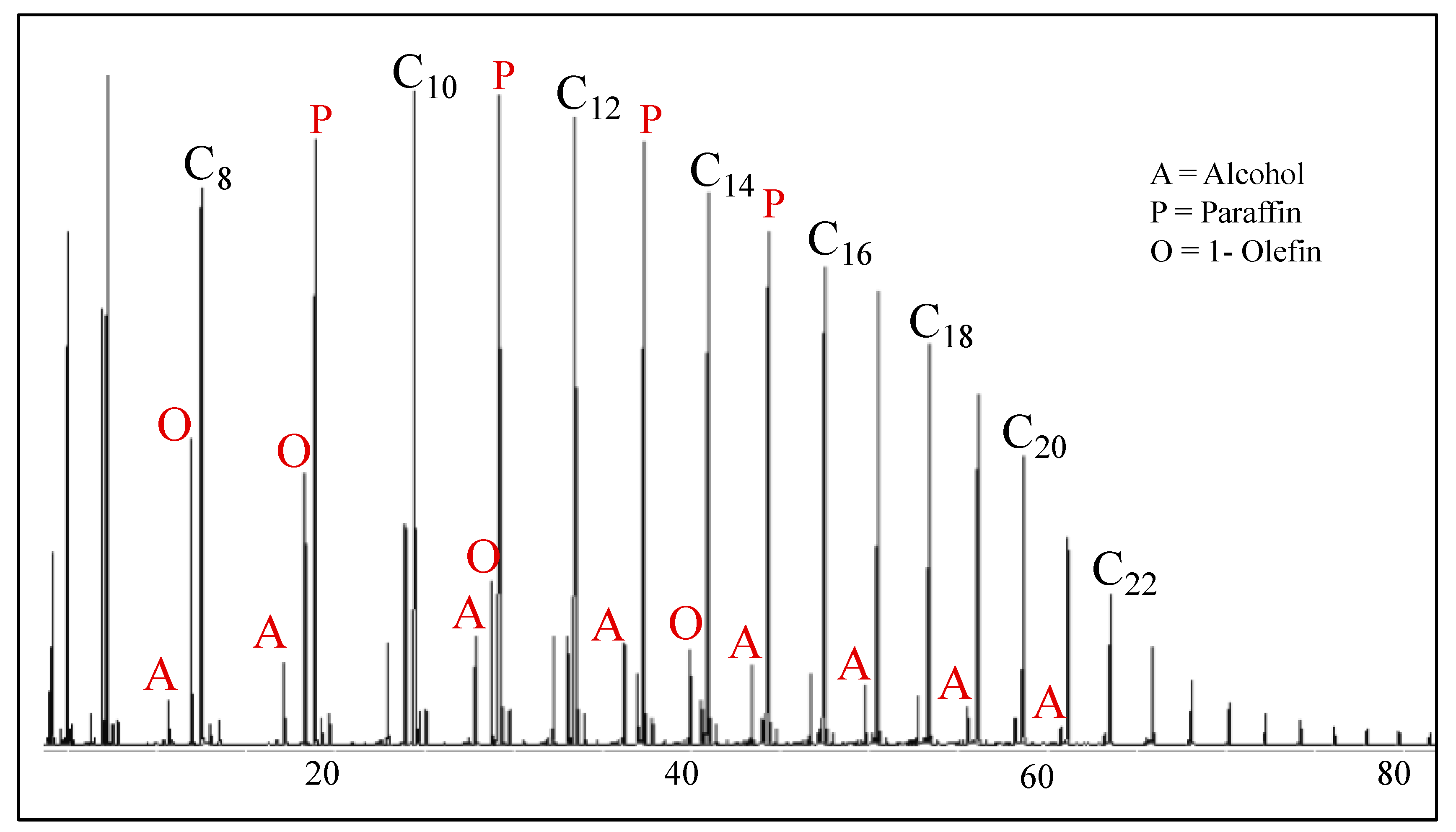
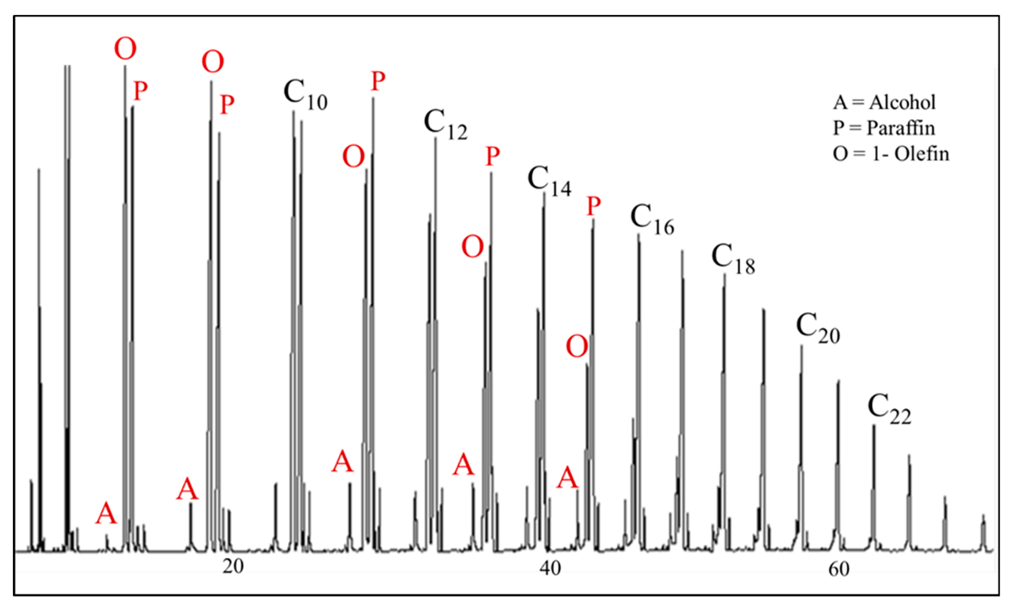
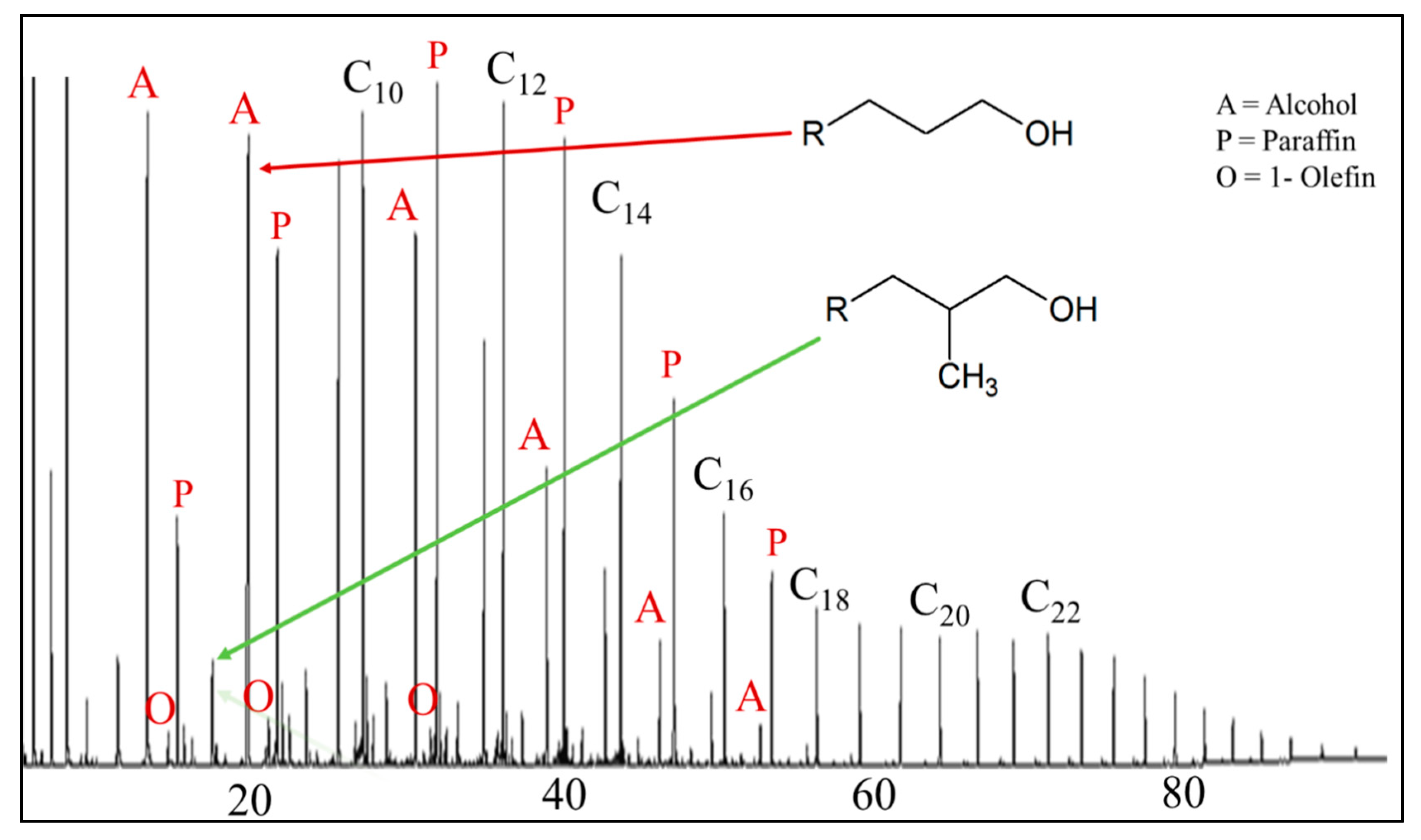
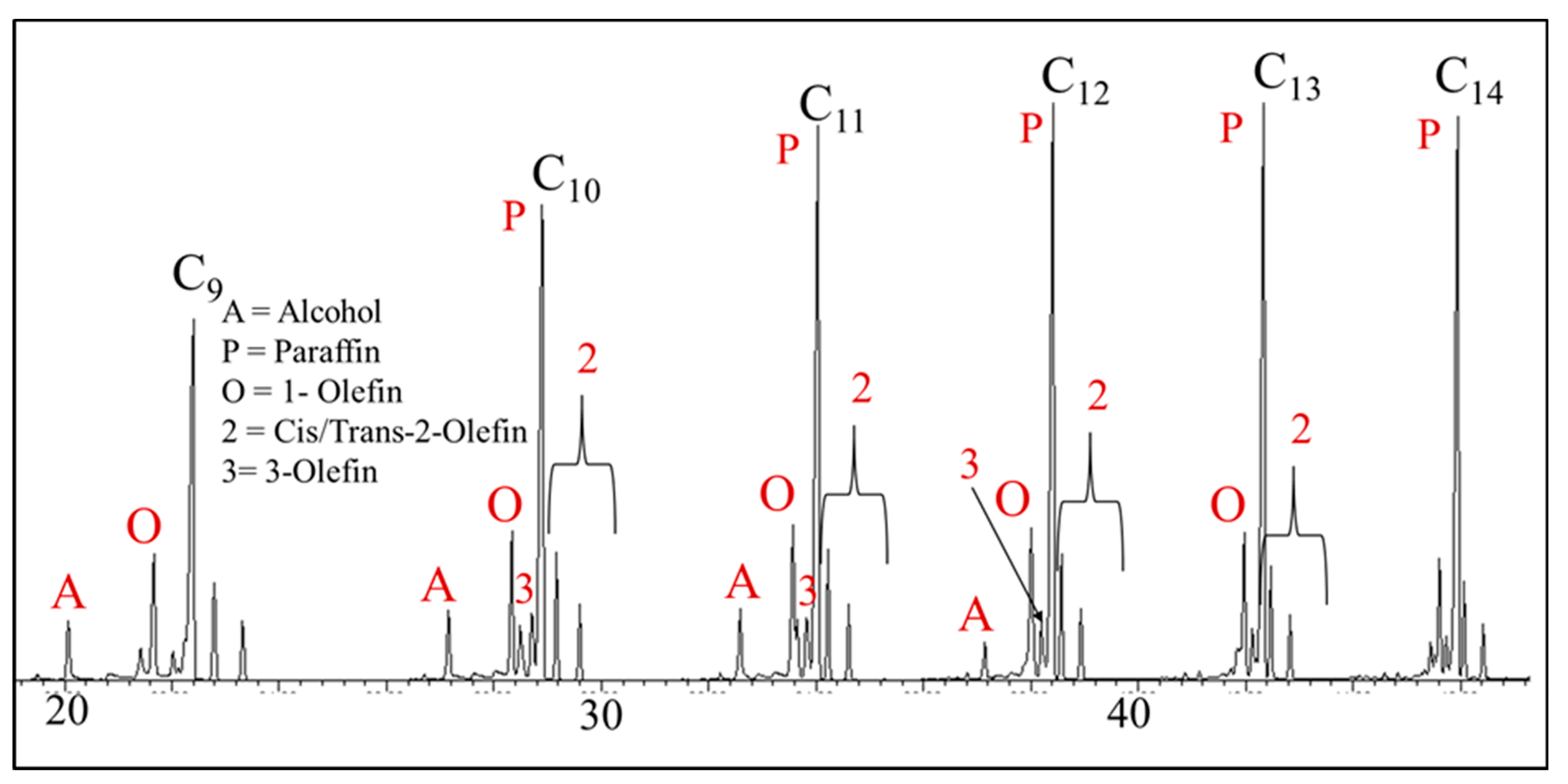
The main FTS products elute in a specific order that is based on our analytical procedure (Figure 11 and Figure 12), where the first peak is the 1-olefin, followed by the paraffin, trans-2-olefin, and lastly, the cis-2-olefin, which ranges from C2 to greater than C70. A variety of hydrocarbon products elute, in groups of the same carbon number, before the 4 major products. The majority of these are methyl branched paraffins and olefins that have the sp2 carbon greater than C2—i.e., more internally along the chain (e.g., cis-3-alkene, trans-3-alkene, cis-4-alkene, trans-4-alkene). These types of products tend to be more prevalent for iron than for ruthenium and cobalt. The products elute in the same order for each carbon number based on type (e.g., 1-olefin, paraffin, trans-2-olefin, cis-2-olefin). The carbon number distribution for the oxygenates also elute in a specific order (Figure 8, Figure 11 and Figure 12) (linear alcohol, ketone, aldehyde and ester).
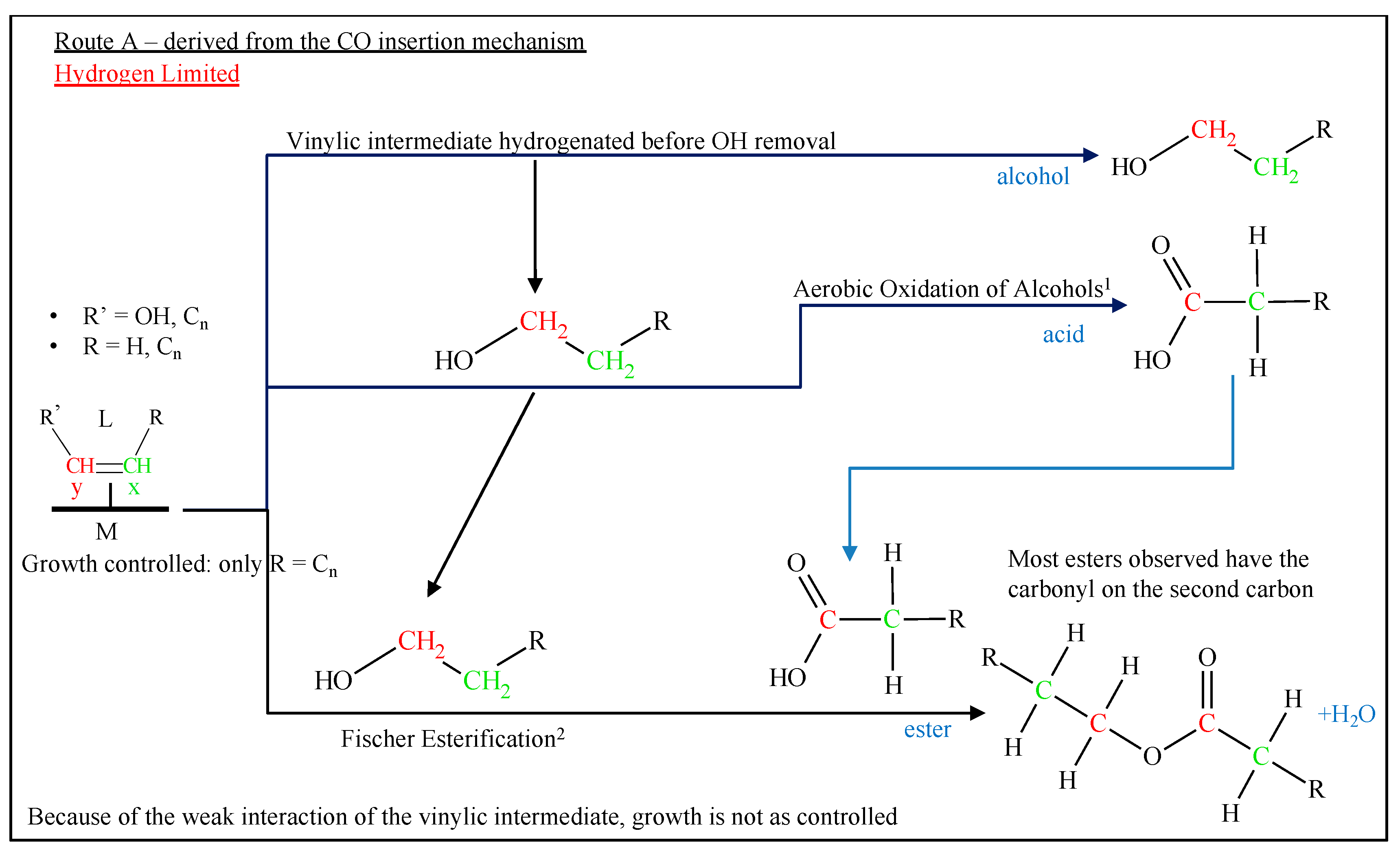
For the entire spectrum of compounds, per carbon number, the first peak in the group is usually the branched material and the last compound to elute for each carbon number group is the cis-2-olefin. The major oxygenate group for all of the catalysts (with the exception of potassium doped iron catalyst with no silica) in the oil products is the alcohol, which elutes from the column before the 1-olefin. The carbon number of the alcohol that elutes has approximately three carbons less than the hydrocarbon peak (i.e., when the C12 hydrocarbons elute, the alcohol that elutes will be nonanol). Other oxygenates, such as esters, ketones, and aldehydes, are two carbon numbers less. Acids (when observed) are typically four carbons less.
Alcohol is the only oxygenate that is present in a carbon molar percentage that is sufficient for analysis of the cobalt and ruthenium catalysts. Depending on certain parameters (such as the metal promoter and support), the alcohol peak may be small, as with the lithium doped iron catalyst (Figure 13), the unsupported cobalt catalyst (Figure 14), and the alumina supported ruthenium catalyst (Figure 15); or, a dominant peak before the 1-olefin, as with a rubidium doped iron catalyst (Figure 16), a silica supported cobalt catalyst (Figure 17), and the titania supported ruthenium catalyst (Figure 18).
A broad assortment of oxygenated compounds, such as alcohols, acids, ketones, esters, and aldehydes, were generated in the CSTR containing an iron catalyst. The range of oxygenates that was found in the aqueous phase was C5 or lower, and any longer chained oxygenated compounds were present in the oil phase. The oxygenates that were in the oil product were ordered based on retention time (RT) (Figure 8 and Figure 12):
  • The ketone regularly falls near the 1-olefin and, as the carbon number increases, the peak moves toward the 1-olefin and it eventually merges with it. The major ketone observed is where the carbonyl is on the second carbon; every ketone that was observed in the GC-MS for Figure 5 and Figure 9 has the second carbon as the carbonyl.
  • Esters, by and large, appear between the trans-2-olefins and cis-2-olefins and, with increasing carbon number, move toward the cis-2-olefin. The major ester observed is also where the carbonyl is on the second carbon; again, every observed ester in the GC-MS for Figure 5 and Figure 9 has the second carbon as the carbonyl and the oxygen between the second and third carbons.
  • The aldehyde usually elutes between the paraffin and trans-2-olefin.
  • Alcohol, which is the predominant oxygenate product in the oil phase, is the only oxygenate separated and verified for the higher carbon number fraction.
The main anomalies observed in this series are from these three catalysts:
  • The Co/ceria catalyst (Figure 19): the linear alcohol peaks are more dominant than the paraffin and there is the presence of the two methyl alcohols.
  • The unsupported K/Fe catalyst (Figure 20): the aldehyde is more dominant than the linear alcohol for some of the shorter hydrocarbons.
  • The NaY supported ruthenium catalyst (Figure 21): the peak that is assigned to 3-olefin is intense enough to be observable for several carbon numbers.

3.2. Mole Fraction

The mole fraction is calculated by means of the raw oil GC data, gas data, aqueous phase data, and the mass of the actual sample collected. The oil and water GC data provide a weight percentage, as the raw data are based on previous studies of hydrocarbon and oxygenate response factors [88,89,90,91]. The alcohol peaks in the oil phase were identified and then the hydrocarbon and alcohol peaks (including the branched hydrocarbons) were totaled based on the carbon number. From equation 3 and the weight fraction, the total moles for the oil with carbon number 1 to n could be found:
T o t a l   M o l e = i   = 1 n ( W F n ×   m o i l ) C n
where Cn is the molecular weight of the paraffin with the chain being n carbons in length and moil is the mass of the oil that is removed from the reactor.
The aqueous phase was separated from the oil phase and each peak of the GC was identified. The raw data were obtained in weight percent and then combined according to carbon number. The calculation to find total moles for the aqueous phase follows the same procedure as for the oil phase.
The gas produced from the reactor can be divided by the molar volume (22.414 L/mol), providing the moles per h of gas produced, since the gas leaving the cold trap is at standard temperature and pressure. The total moles can then be calculated from the mol/h by determining the difference in the time-on-stream (TOS) of when the sample was taken as compared to the previous sample. The samples were collected as the run time increased for each of the catalysts. Once the total moles were found for the gas data, the oil data, and the aqueous data, the total distribution for that specific sample could be calculated. Thus, the moles of carbon of each product could be related to the moles of CO consumed.

3.3. Chain Growth Probability Factor (α)

3.3.1. Iron

The Na, K, Rb, and Cs run at low conversion produced enough oxygenate peaks to be visible in the oil phase. Examples of the ASF plot for cesium promoted iron (Figure 22 and Figure 23) show the chain growth probability factor for the hydrocarbons and the oxygenated compounds. Some oxygenate peaks for specific iron runs (Li and unpromoted) could be identified by the MSD while using single ion monitoring (SIM) of specific fragments produced by the electron impact source (EIS). However, the oxygenated products were below the limits of detection (LOD) and could thus not be considered.
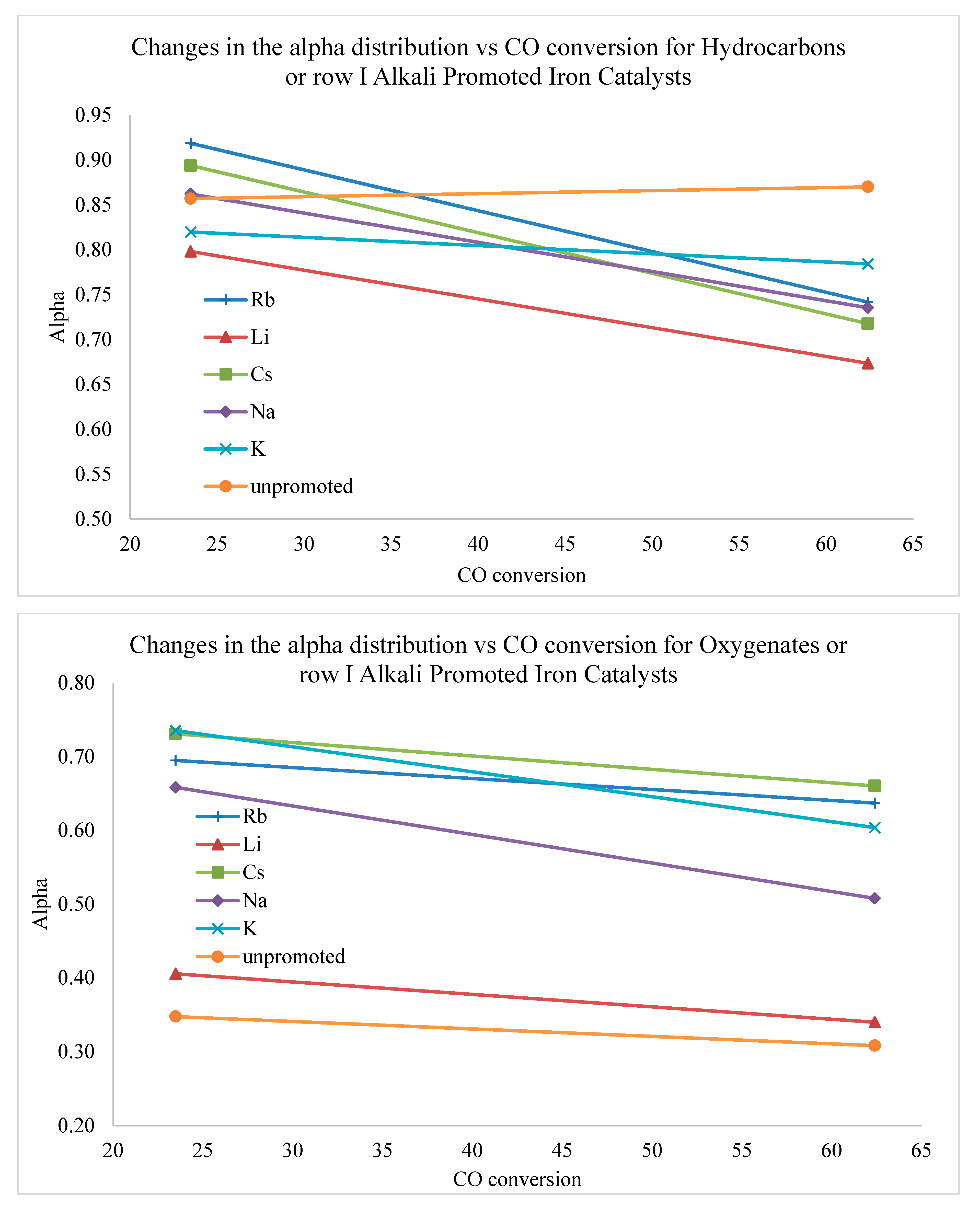
The chain growth probability factor of the hydrocarbons for alkali metal doped iron catalysts was lower (α = 0.75 ± 0.07) for the high CO conversion samples (Table 1) when compared to that of the low CO conversion samples (α = 0.86 ± 0.04). The oxygenated compounds additionally displayed a lower α value (α = 0.51 ± 0.15) for the high CO conversion samples as compared to the low CO conversion samples that have an average α of 0.56 ± 0.18. The variation between the average α plots for the oxygenates was smaller than that of the hydrocarbons for the different conversions. However, there was a larger deviation in α values for the oxygenates from the promoted catalysts when compared to that of the hydrocarbons.
α values of the oxygenates for the Na and K promoted Fe catalysts were the most affected by the change in CO conversion. The Li promoted Fe catalyst had the lowest α value, being significantly lower than that of other promoted catalysts, and it remained unchanged at different conversions. Rb and Cs promoted Fe catalysts consistently had the highest α values, which only changed slightly by changing CO conversion (i.e., average CO conversion across all the high CO conversion runs was 62.4% ± 2.56 and average CO conversion across all low CO conversion runs was 23.5% ± 4.30).

3.3.2. Cobalt

Examples of ASF plots for cobalt catalysts are displayed in Figure 24 and Figure 25. The α for the hydrocarbons that are produced from a cobalt catalyst is 0.82 ± 0.04 (Table 1). Two samples were taken as the run time increased, within each of the three runs. While there are variations in the CO conversions, they are within (±4%). When considering the conversion rates among samples, the chain growth probability factor should remain somewhat the same from sample to sample. There are differences among the α values with support type, whereby the alumina supported catalyst (Table 1) had the highest α value of 0.88, whereas the carbon supported catalyst displayed a lower α of 0.76. All of the supported catalysts had higher α values for oxygenates in comparison with that of unsupported cobalt. The effect of the support for oxygenated materials has been corroborated [98,99,100].

3.3.3. Ruthenium

Figure 26 and Figure 27 display examples of the ASF plot for titania and alumina supported ruthenium catalysts. Based on the results in Table 1, the α values for the hydrocarbons and oxygenates were slightly higher for cobalt than ruthenium (Table 1). A reason for this is that the wax based materials were not added, causing larger deviation with the ruthenium catalyst than with cobalt. The overall α plots for the ruthenium catalysts were more uniform, independent of the support. Yet, in the case of oxygenates, α is quite different, indicating that the rate of growth for oxygenated materials may depend more so on the support-metal interfacial contact area (i.e., the perimeter of metal particles in contact with the support) than that of hydrocarbon growth.

3.4. Specific Product Selectivities

3.4.1. Iron

Ngantsoue-Hoc et al. [85] discussed the ratio of ethene to ethane, where Rb, Cs, and K promoted Fe catalysts produced the highest ratio. Extending this range to C25, the trend continues to hold for the major components (1-olefin, paraffin, cis-2-olefin, and trans-2-olefin), where Rb, Cs, and K promoted Fe catalysts produced the highest selectivity of olefins (on a carbon molar percentage basis, Table 2). The undoped catalyst had the lowest selectivity to olefins, which was much lower than in the case of Li and Na promoted Fe catalysts. This pattern is consistent for both the high and low CO conversion samples, where Rb, Cs, and K promoted iron catalysts produced the highest olefin contents.
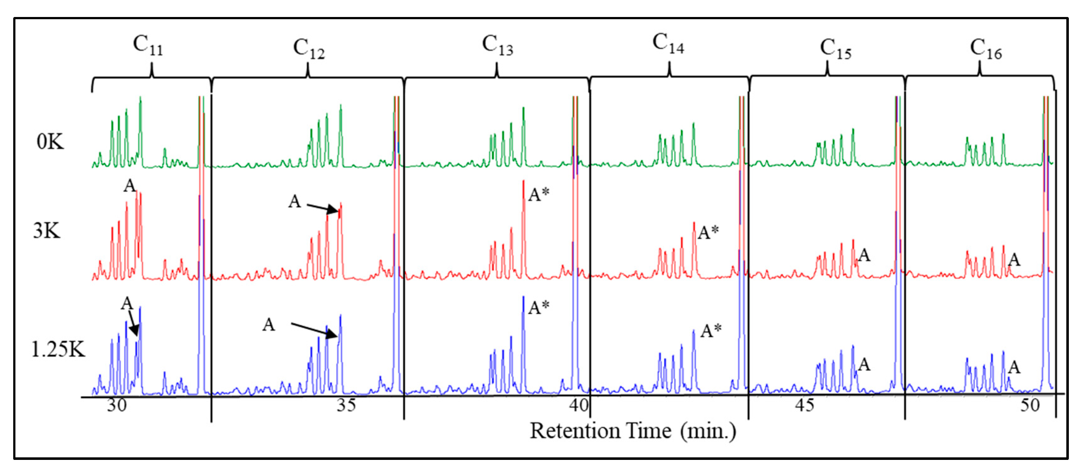
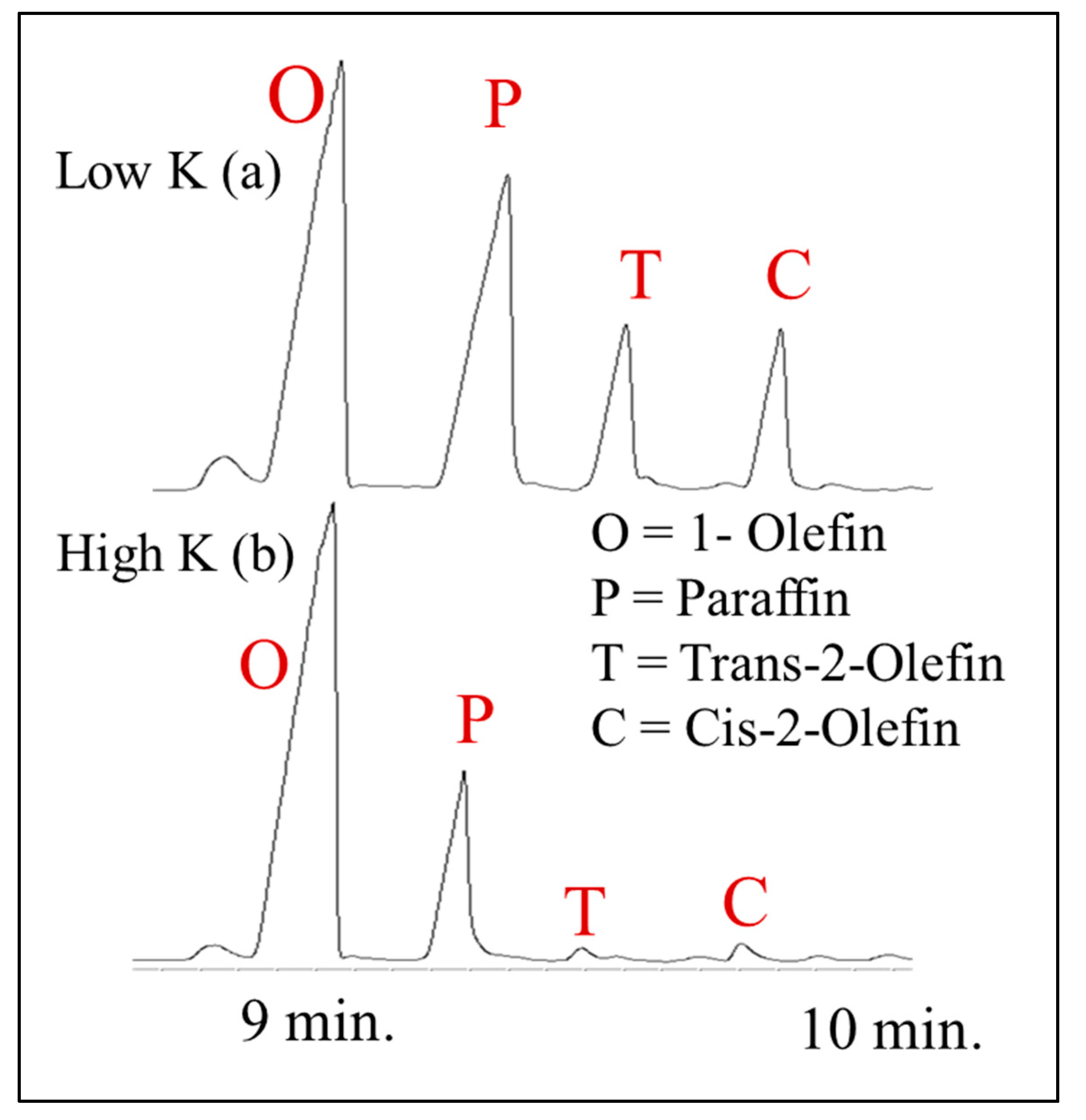
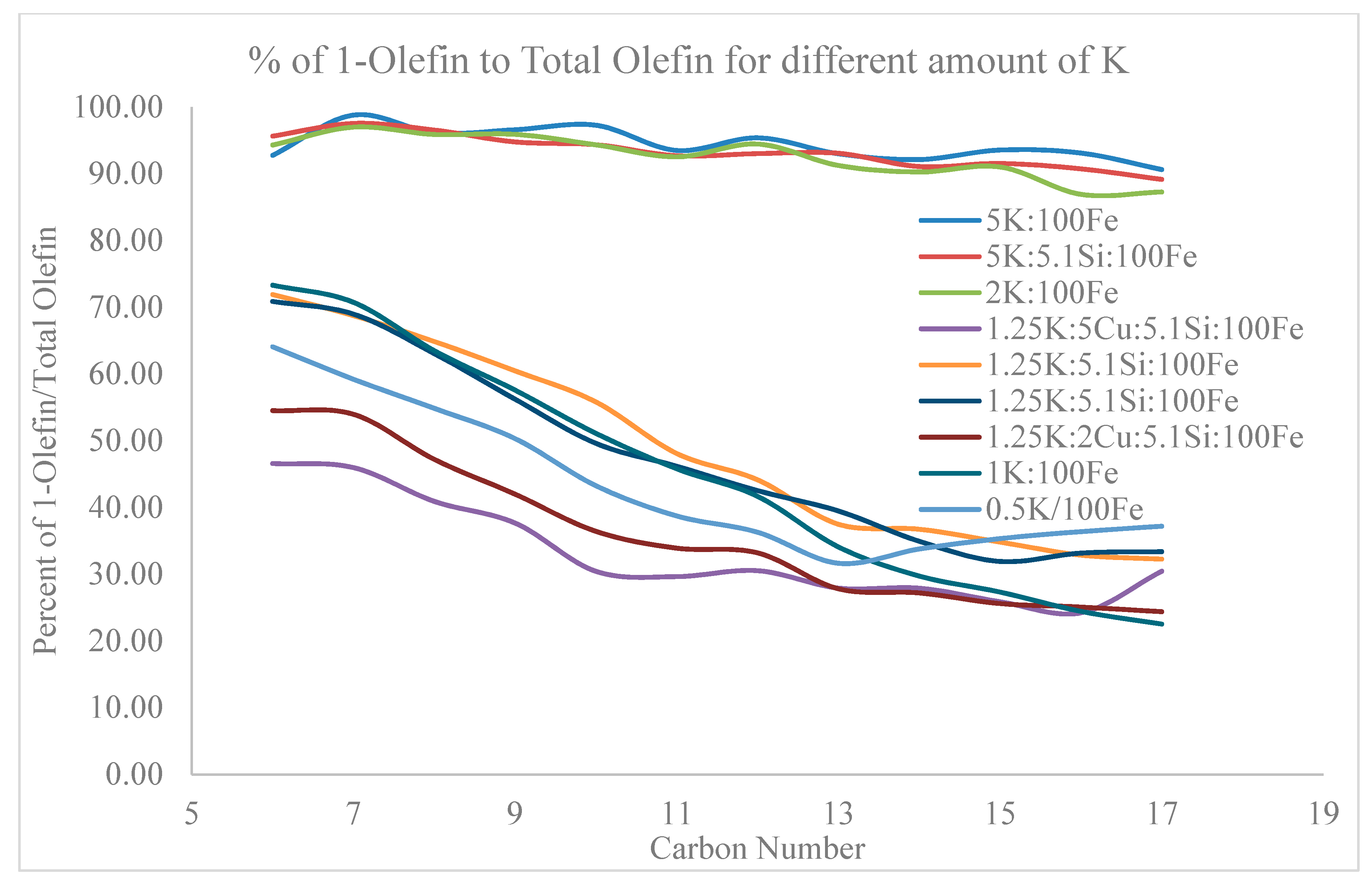
Overall, two main trends are observed in the FTS hydrocarbon products, as shown in Figure 28. The first trend “a” is observed with lithium, sodium, and low atomic ratios of K (less than 2 atomic ratio to iron) on Fe, and independent of the atomic ratios of copper and silica for the samples that were tested (Figure 29). The actual results are based on the weight fraction from the chromatography in the oil phase. Trend “a” is where the 1-olefin is lower or nearly the same as the relative paraffin material, and the trans-2-/cis-2-olefins are high, respectively. This trend holds for the lighter hydrocarbons (Figure 8: A, 13), but as the carbon length increases, the weight fraction of the paraffin increases. This could be due to secondary reactions, such as hydrogenation, reinsertion, etc. Trend “b” from Figure 28 is observed with Rb promoter, Cs promoter, high atomic ratios (larger than 2 atomic ratio of potassium to iron) of K promoter and supports like manganese. Trend “b” displays the 1-olefin as being much greater than the respective paraffin (as shown in Figure 16 and Figure 30), and the trans-2-/cis-2-olefins are low or virtually absent. Once again, this mainly holds for the shorter chained hydrocarbons, but as the chain length increases, the paraffin starts to dominate. This is a general description of the chromatographic distribution of the products, as the selectivities may change depending on the catalyst composition (e.g., the atomic ratios of K). However, there appears to be an inverse relationship in the production of the olefinic material (i.e., as the selectivity of the 1-olefin increases, it decreases for the 2-olefins). This phenomenon can also be found on the single methyl branched material. As the 1-olefinic selectivity is increased, the branching decreases. These relationships can be fully observed when comparing all of the figures side by side (i.e., Figure 8: A, 13, 16, 28–30).
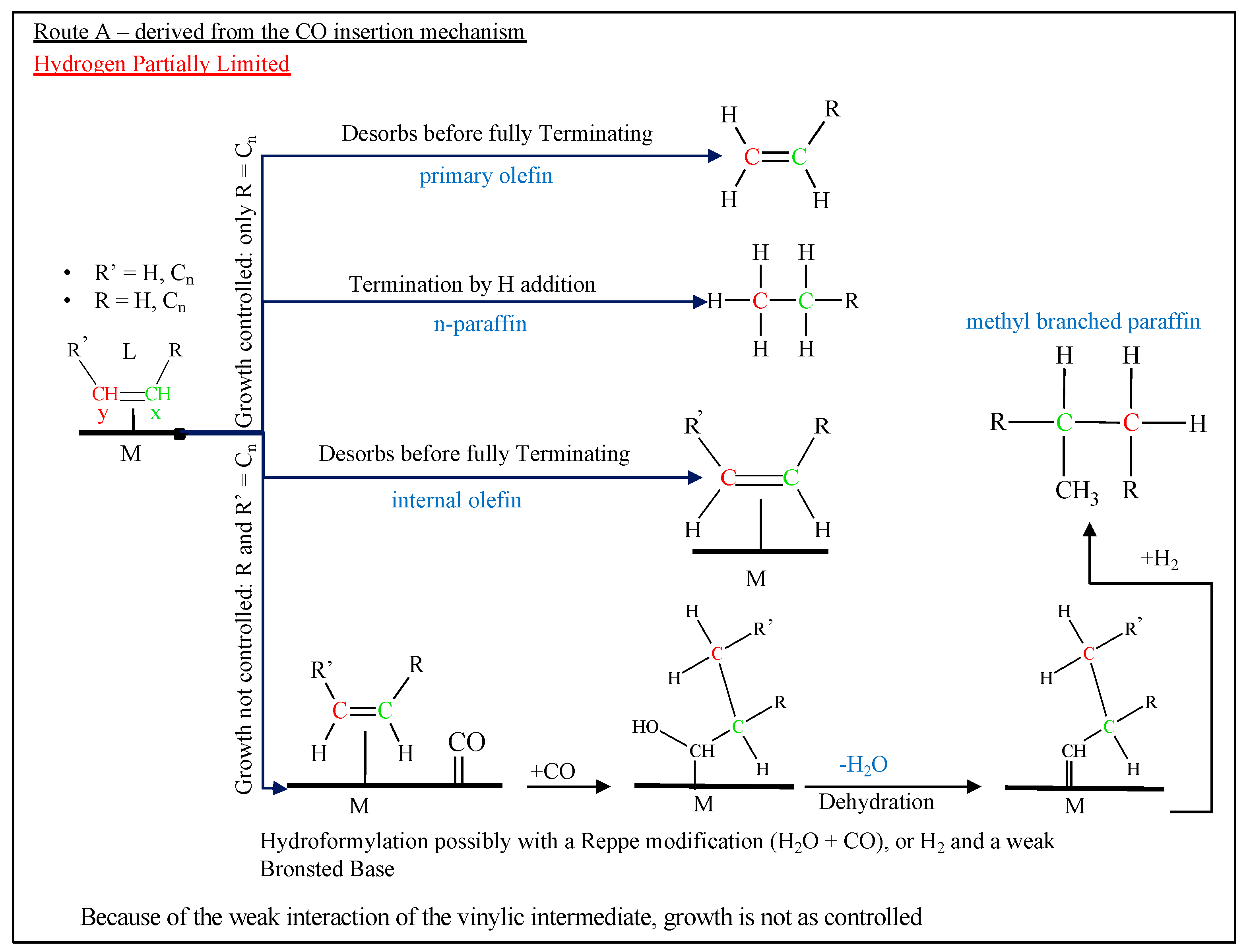
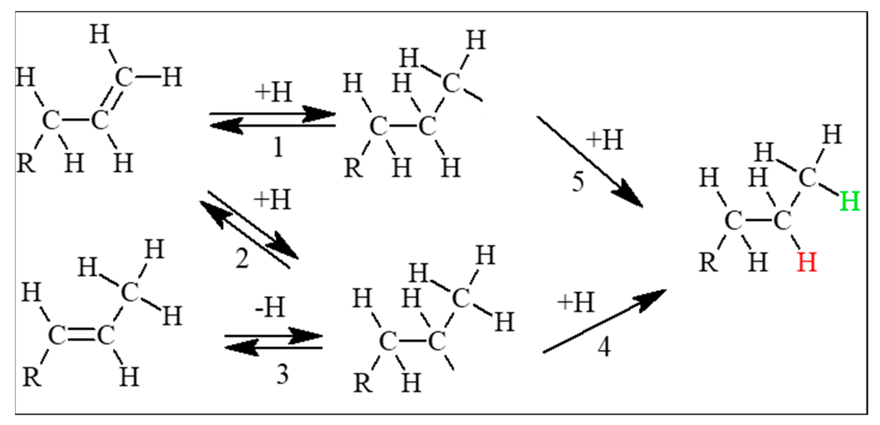
Iron, unlike cobalt (Figure 17) and ruthenium (Figure 18), also produces a higher selectivity of branched hydrocarbons (Figure 9, Figure 10, Figure 11, Figure 12, Figure 13, Figure 16 and Figure 31). The majority of branched hydrocarbons, as previously displayed in Figure 9 and Figure 10, is the single methyl branched paraffin. The single branched materials always display the 2-methyl functional group and the branched materials contain mono-methyl groups that go all the way up to the middle of the chain (i.e., decane displays 2-methyl, 3-methyl, 4-methyl, 5-methyl; dodecane displays 2-methyl, 3-methyl, 4-methyl, 5-methyl, 6-methyl). The 2-methyl and 3-methyl single branched paraffins are normally the greatest and then decrease in the FID raw data—peak area (weight %)—as the methyl is located toward the center of the chain. The methyl branched isomerized materials, however, are not as evident for a typical cobalt catalyst. This is shown in Figure 14 for a 100% cobalt FTS run. These materials are detected more when CO binding is weak, due to insufficient back bonding. Route A, binding of the vinylic intermediate is weak, as displayed in Figure 9, Figure 10, Figure 13, Figure 28, Figure 29 and Figure 31, display high amounts of the internal olefins, while the 1-olefin is lower. The selectivities of isomerized products and internal olefins both trend inversely to the 1-olefin.
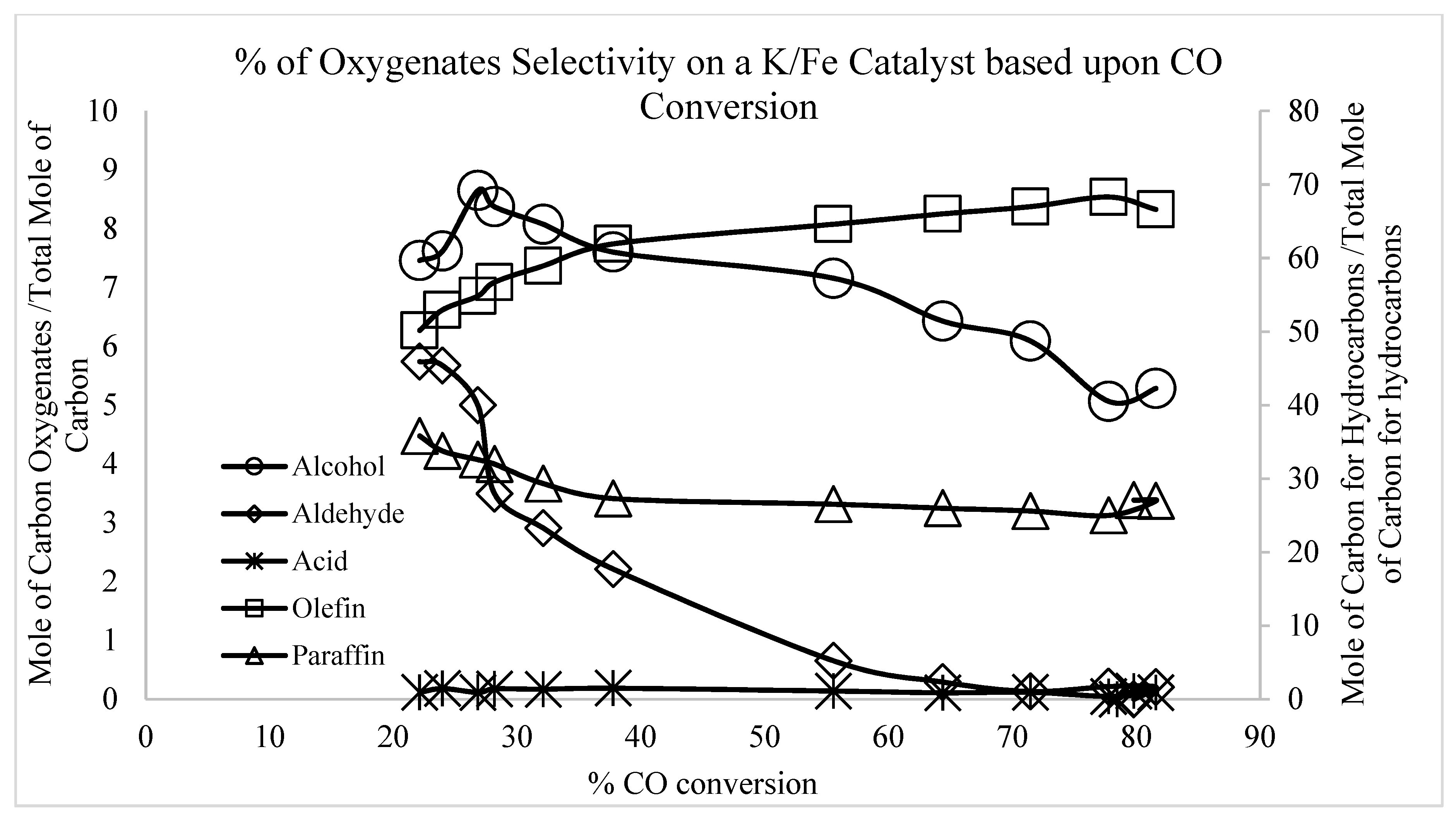
Oxygenate production increases as the paraffin content decreases, where the Rb- and Cs-doped iron catalysts had the highest carbon mole % for oxygenate content. For example, the total carbon mole % of oxygenates for Rb- or Cs-promoted Fe is more than three times that of the K-promoted iron catalyst at high CO conversion. Furthermore, unlike the K promoted Fe catalyst, the total carbon mole % of the oxygenate content does not seem to depend on CO conversion (Table 2). The low conversion sample for the potassium doped iron catalyst produced a higher selectivity of oxygenates, which was more than three times the selectivity when compared to that of the high conversion sample. The high CO conversion sample for the Li doped iron catalyst displayed the lowest selectivity of oxygenates for the Group I series (i.e., more in line with cobalt alumina), whereas the sodium doped iron catalysts produced the lowest selectivity of the oxygenates at low CO conversion. The undoped catalyst produced a much lower selectivity of oxygenates (Table 2) than the promoted iron catalysts for the Group I alkali series (unsupported iron—i.e., 100%Fe—had the lowest selectivity of oxygenates of all the catalysts that were tested, even unsupported cobalt). K- and Li-doped iron catalysts exhibited the largest differences in carbon molar percentages for oxygenate selectivity between the high and low CO conversions. Cs and Na doped Fe catalysts had a smaller difference, whereas Rb and the undoped iron catalysts exhibited virtually no change in the selectivity of oxygenates that are produced at both high and low CO conversions.
The manganese supported iron catalyst displayed the highest fraction of olefins, mostly consisting of the 1-olefin (Figure 30), of all the catalysts tested. The oxygenated products were present, but manganese mainly promoted olefin selectivity.

3.4.2. Cobalt

Unlike typical iron catalysts, conventional cobalt catalysts consistently produce a very clean chromatogram where the straight chain paraffin is predominant. The product distribution that is displayed in the oil and wax products for cobalt seems to be more dependent upon the support, and less so on promoter type (Pt, Ru, Ag) and loading; the promoter does affect the distribution, but it mainly affects methane and the other hydrocarbon selectivities [101,102]. The addition of potassium to cobalt FT catalysts resulted in a promotion of chain growth [103], but the effect reached a maximum. The paraffin still dominates for the entire range of products (Figure 14, Figure 17 and Figure 32), with only slight fluctuations in the alcohol and olefin contents. From the results of catalyst testing, in hydrocarbons that were longer than C8, the paraffin was more dominant than the olefin. In only one catalyst, cobalt promoted with ceria, was the paraffin dominated by another product—not the olefin, but rather the alcohol (Figure 19).
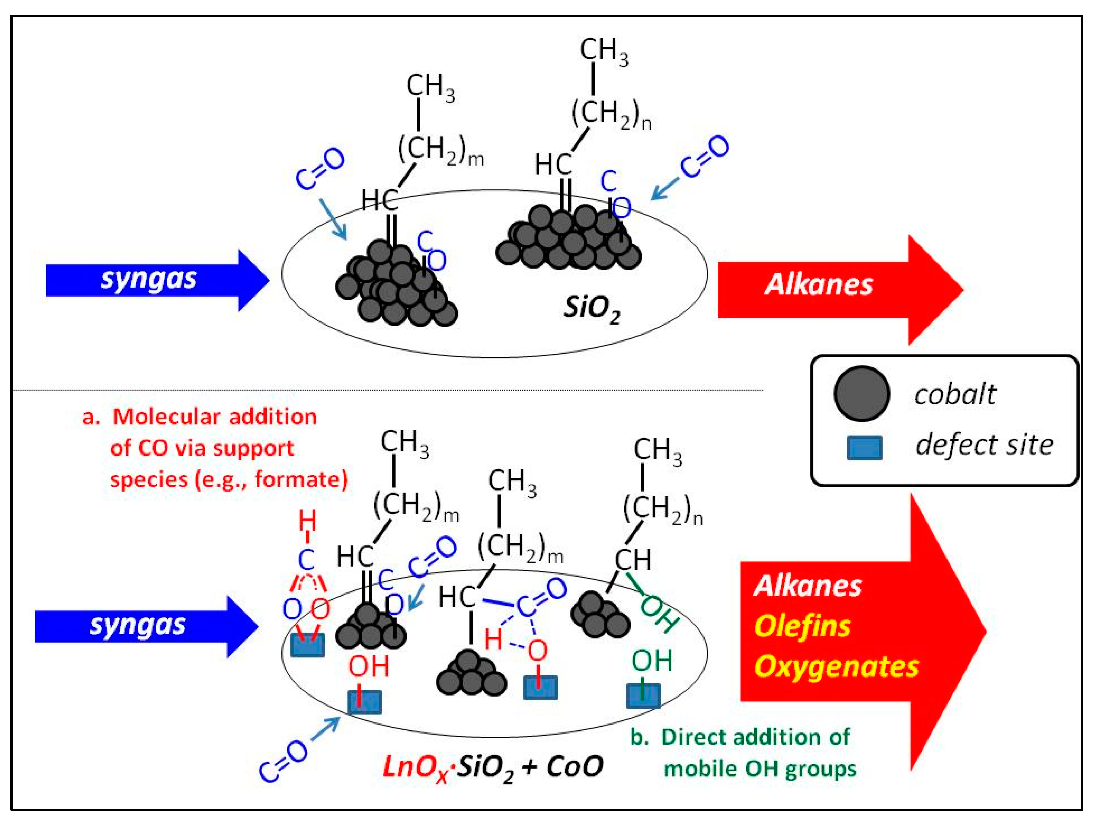
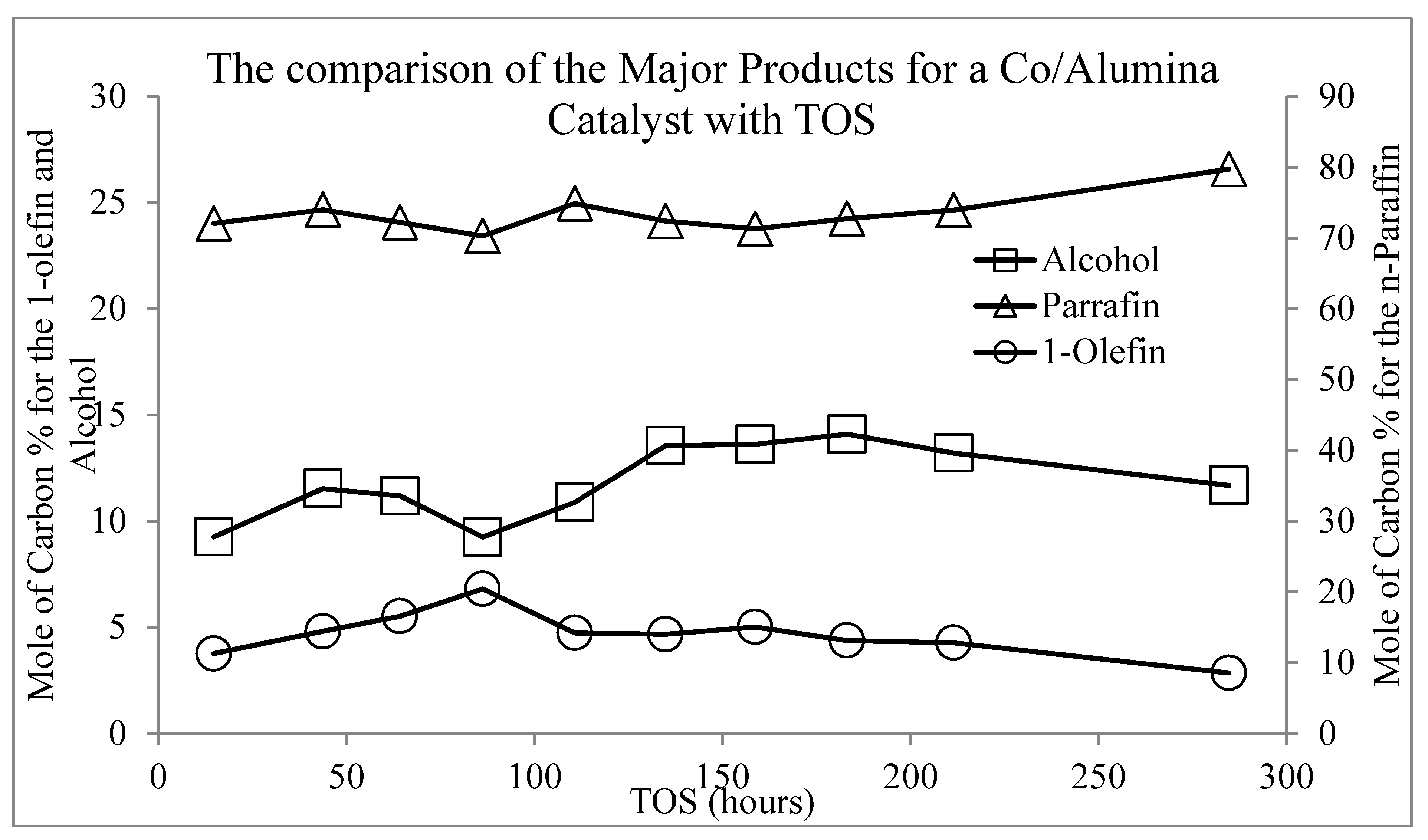
Recent work that was by the Davis group [40,41,42,104,105] focused on attempting to make cobalt catalysts behave more like iron catalysts (i.e., consisting of Fe carbides in close vicinity to defect-laden Fe oxides) by placing Co nanoclusters in close proximity to the reduced defect sites (e.g., O-vacancies and their associated Type II bridging OH groups). As depicted in Figure 33, one view is that (a) CO reacts with Type II bridging OH groups to form formate species and that these formate species can transfer molecular CO across the metal-support interface to terminate the FTS hydrocarbon chains. Or, (b) the mobile bridging OH groups may add directly. Hydrogenation of the added terminal -CO would lead to linear alcohols, while dehydration is proposed to result in linear olefins. Interestingly, as a function of time on-stream, Ce-containing Co catalysts produced significantly higher selectivities of olefins and oxygenates, with the oxygenates being almost exclusively linear alcohols. Surprisingly, as a function of time on-stream, the olefins selectivity decreased with a concomitant increase in the selectivity of linear alcohols, such that the sum of olefins + linear alcohols was virtually constant with time on-stream, suggesting that the two products were derived from the same adsorbed species. In examining Table 2 and summing up the total of olefins + linear alcohols, it is clear that ceria and titania supported cobalt catalysts exhibited the highest selectivity to these products (55.4% and 49.7%, respectively), lending support to the proposed mechanistic viewpoint that defects in the oxide promote total olefin + linear alcohol selectivity. On the other hand, unsupported Co and Co that was supported on relatively inert supports (Al2O3, carbon, and SiO2) exhibited significantly lower selectivities to olefins + linear alcohols (15.6%, 18.0%, and 24.6%, respectively), as shown in Figure 33.

3.4.3. Ruthenium

Ruthenium catalysts more closely trended to the cobalt catalysts, where the bulk of the product observed was straight chained paraffins. Compared to cobalt catalysts, ruthenium catalysts produce a higher selectivity of olefins, which depend on the support. Furthermore, ruthenium on NaY produced sufficient 3-olefin to be observable over several hydrocarbon lengths (Figure 21). The titania supported ruthenium catalysts displayed a higher selectivity of olefins, which exceeded that of paraffins up to the diesel range. However, unlike iron, the four major products (by selectivity in molar carbon %: paraffin, 1-olefin, cis, and trans 2-olefin) were clearly observed, being similar to cobalt. Furthermore, as with cobalt, little to no methyl branched material was observed in the chromatograph, and no oxygenates were detected other than linear alcohols.
The selectivity of oxygenates for all of the ruthenium catalysts (Table 2) was slightly higher (1.3% higher for alumina, 0.8% for silica, and 0.5% for titania, respectively) than for the cobalt catalysts (alumina, titania, and unsupported). However, none of the ruthenium catalysts displayed oxygenate selectivity that was as high as the low CO conversion K-promoted Fe catalyst, the Rb-promoted Fe catalyst, the Cs-promoted Fe catalyst, the Co/carbon catalyst, and the 0.5%Pt/Co/ceria catalyst. However, the distribution was much like that produced by a typical cobalt catalyst, where the only oxygenates found were linear terminal alcohols.

3.5. A Mechanistic Description

3.5.1. The Electronic Nature of the Active Metal

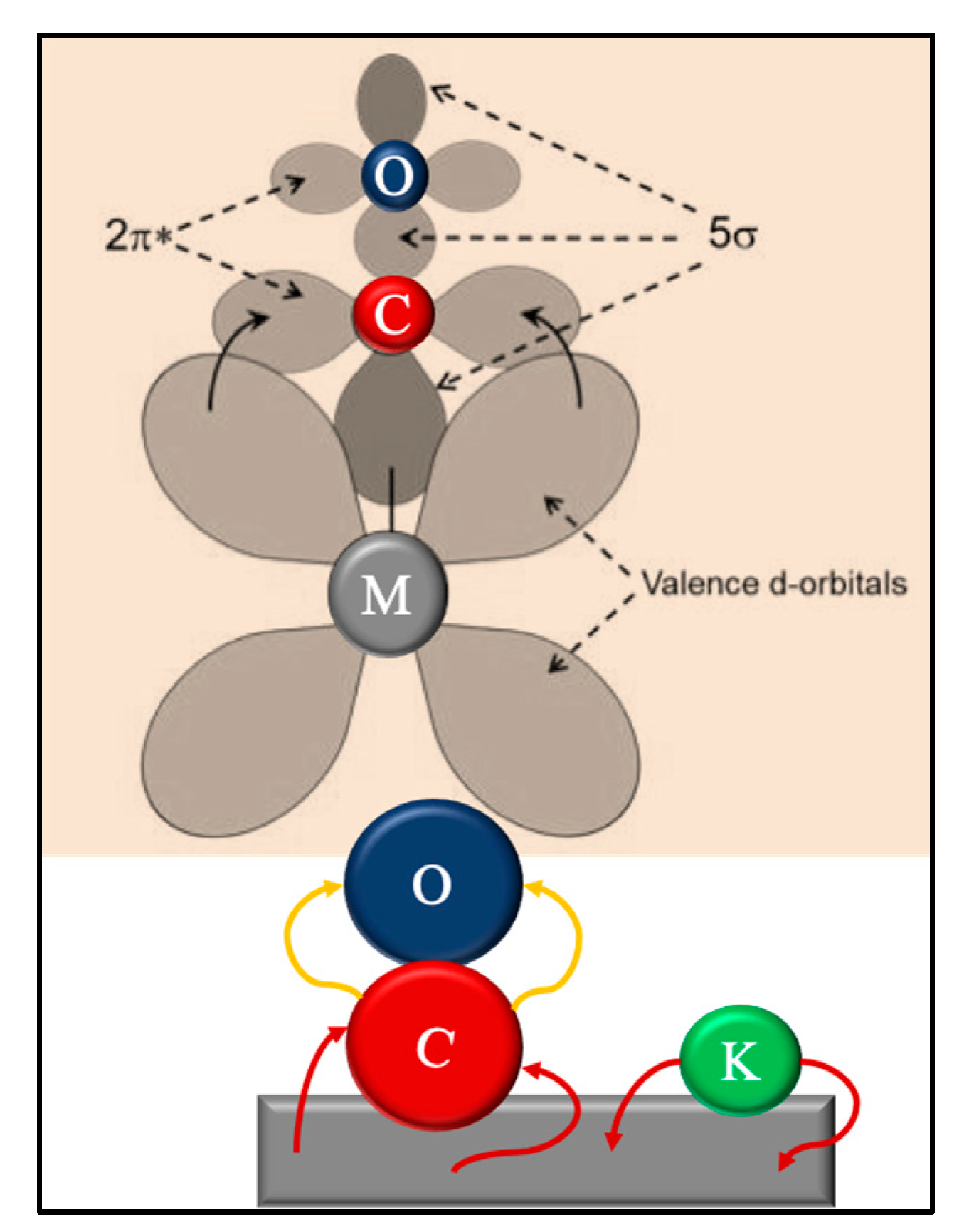
The underlying concept behind the proposed mechanistic routes—to be discussed—is driven by the localized electronic environment of the active FTS metal (at low temperature), which determines the degree of back-donation of electron density. The nature of CO, a π-acceptor ligand, has the capability to interact with a metal in three ways, depending on its environment, through: (1) a weak back donation -M-C≡O; (2) a semi-strong back donation -M=C=O; and/or, (3) a strong back-donation -M≡C-O [106]. The richer the electron density of the active metal, the more back donation to the 2π* anti-bonding orbitals of CO (Figure 34) [106,107,108]. This localized electronic structure of the metal can be changed by the addition of a promoter (e.g., with iron catalyst, alkali is used). These additions to the active metal could potentially be a way of “tuning” the FTS catalyst for CO adsorption (with the potential to affect H2 as well); too poor and CO adsorption is weak, causing issues with CO hydrogenation; too rich and CO adsorption is too strong where carbonaceous deposits begin to form. Typically, because of orbital overlap, even though metals, like copper, have more electron density to provide, the large d-orbitals from the metal do not pair well with the smaller carbon-carbon π orbitals and greatly limit this capability [109]. As a trend, the transition metals toward the left would yield better back bonding; yet, the rate at which oxidation occurs for those on the left apparently diminishes the capability for FTS [110]. Discussions here will only revolve around the differences among the active FTS catalysts. Further discussions of iron will be in the active carbide form, not the metallic form.
Once the CO is adsorbed, vinylic species are described to form and serve as the active intermediates, where the FTS chains grow to eventually terminate. Many works from the literature suggest that the rate determining step involves hydrogen [45,49,100,110,111,112,113], but not the dissociation of H2 [114,115,116,117,118]. As a result, the stabilization of chain growth intermediates may rely more on the tuning of the catalysts, specifically for the reactivity of CO. However, this does not discount observations regarding the competitive dissociation of H2 in Ni and Co catalysts, where heavier oils and waxes that were produced from FTS interfere with hydrogen dissociation [119,120].
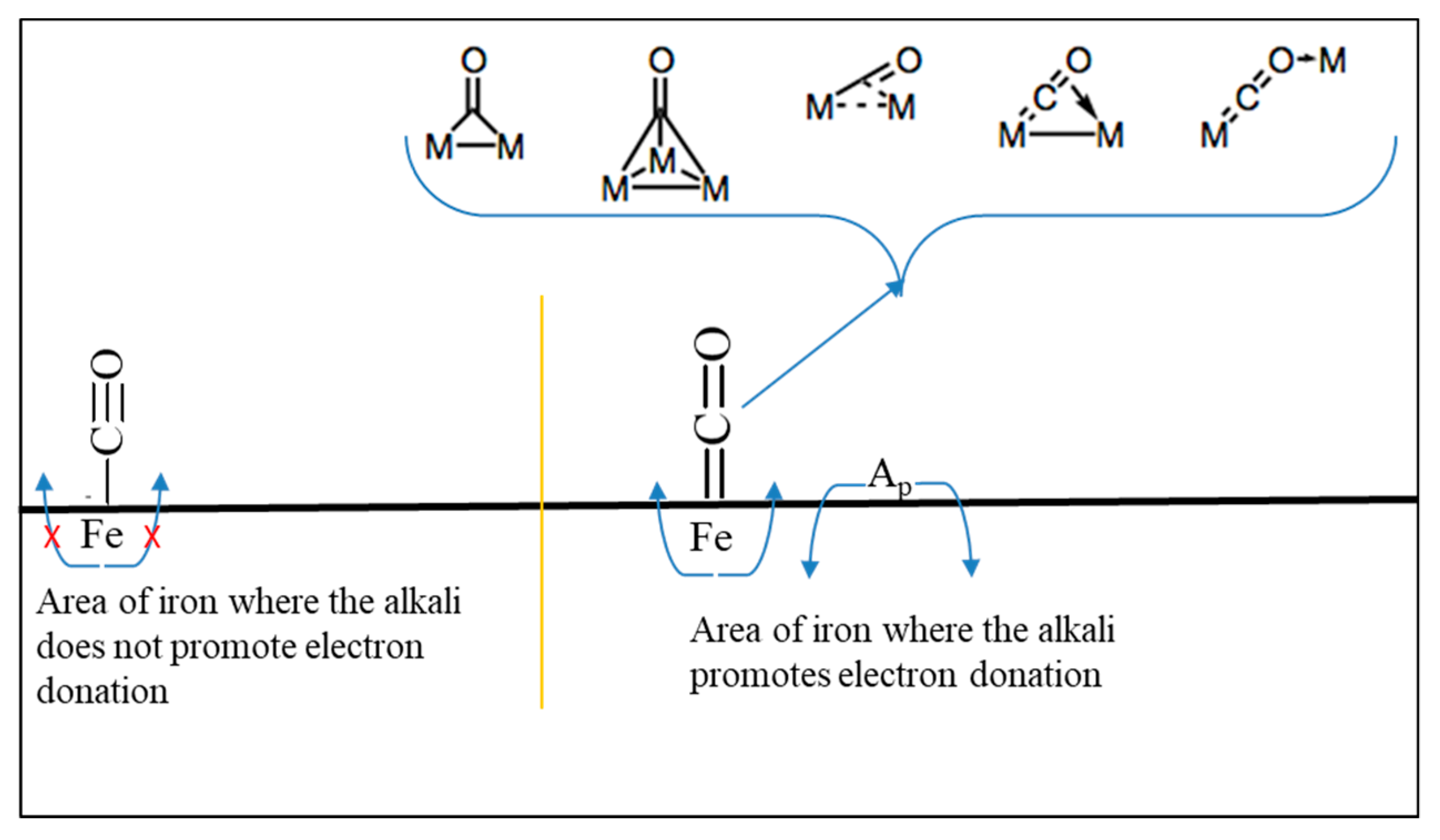
Since both the vinylic intermediate and CO exhibit π bonding, they will both be susceptible to electronic back-donation from the catalyst surface. Thus, if the CO adsorbs weakly, then the vinylic intermediates will not be stabilized, making their formation difficult, such that most of the carbon will form methane. The vinylic intermediates that do form will weakly adsorb, and the growth will not be as structured. This mechanism is proposed to be favored on iron carbide (Figure 31). If CO dissociates readily and H2 is not significantly suppressed, again methane selectivity is observed to be high. Because CO readily dissociates, the formation of vinylic intermediates will be difficult, as the ones that do form could easily dissociate back to a single carbon atom. The active catalyst will have high surface coverage, which leads to coking, which is proposed to be the case with nickel catalyst. However, if CO adsorbs and remains stable enough (e.g., to form enol species or other relevant species), the vinylic intermediate that subsequently forms (e.g., from the condensation of two enol species) will also be stabilized, allowing for controlled chain growth. This is proposed for Ru and Co catalysts (14, 15, 17, 18, 21, 33), where the main products (i.e., linear paraffins and linear 1-olefins) take up the bulk of the distribution, with few minor products being observed. Lastly, if CO dissociates readily, as observed with K promoted catalysts, and further observed with catalysts that are promoted by the heavier alkali metals (e.g., Rb, Cs), the main fraction of the products consists of linear paraffins and 1-olefins. However, mono-methyl branched paraffins and olefins, whose distributions appear to follow a specific trend (to be discussed), are contained in the remaining products. Since H2 is limited, the vinylic intermediates will desorb without hydrogenating, resulting in alkenes and oxygenates (acids, aldehydes, esters, and alcohols), which limits paraffin production (Figure 11, Figure 12 and Figure 20). Cobalt catalysts that were modified by supporting the cobalt nanoparticles on defect-laden carriers were, as discussed previously, shown to produce linear olefins and linear alcohols; however, only iron FTS catalysts were found to produce a variety of oxygenated materials.
Deviations in the product selectivity are the highest for iron (i.e., iron selectivity appears to be more tunable) and much more so than for Co, Ru, and Ni. These deviations are apparent even in the physical attributes of the products (e.g., color, as shown in Figure 2). The deviation suggests diversity in the active phase (e.g., brought on by addition of K) [121]. A reason why different carbides are more active toward FTS (without K) could be due to the ability of iron to donate its electron density to CO. This could be a reason certain phases, such as cementite, are not as active as others, such as Hägg. However, there are several factors (e.g., morphology) that come into play [121].
The important intermediate considered in mechanistic schemes presented is adsorbed 2-carbon ethylene species, which was previously proposed in early work [122]. However, unlike previous work, chain growth likely does not proceed via ethylene, but rather by single carbon atoms. Evidence has shown that an ethylene like intermediate acts as a chain initiator, not as a chain propagator [122]. Furthermore, propylene was found to exhibit hydrogenation ability, but not a significant capability to initiate chain growth [122]. Because of the similarity in π bonding that the proposed vinylic intermediate and CO exhibit, when CO does not bind well to the catalyst surface, neither should the vinylic intermediate. As the binding of the vinylic intermediate is weak, the chain growth would not be as ordered (i.e., directional, forming linear chains); thus, methane and methyl-branched materials would be expected to form in higher selectivity. If CO dissociates too easily, then the adsorbed vinylic intermediate would follow suit, and thus methane would be expected to be a major product. If CO binds well, but H2 is not as accessible, then the vinylic intermediate should be stabilized, but the termination by hydrogenation to paraffin would be limited, leading to higher selectivities of olefins and oxygenates. The fact that olefins have been found to reincorporate into growing chains on cobalt and ruthenium lends some support to the proposed vinylic intermediate [121].
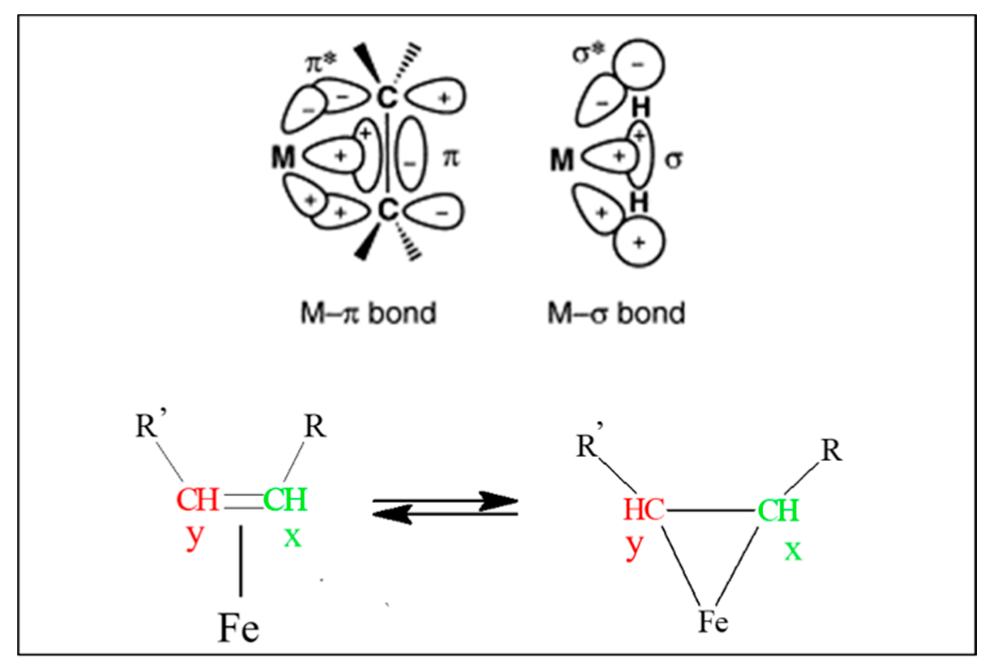
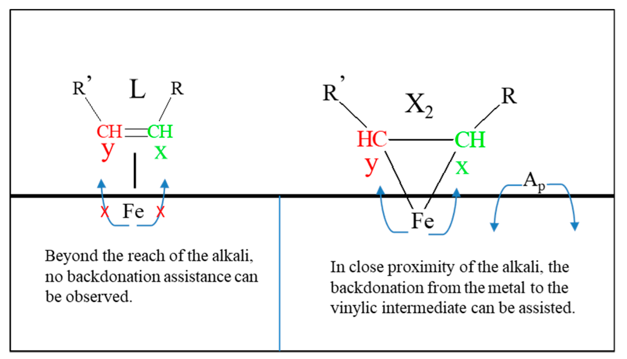
The reason for the sp2 carbon-carbon interaction is that olefins are π-acceptor ligands; their π orbitals interact with the d-orbitals of the metals, as shown in Figure 34. These alkene interactions are taken from the Dewar-Chatt-Duncanson model [123], which describes how alkene ligands interact with metals, and how these interactions between ligand and metal are dependent on the electronic density of the metal. The vinylic intermediate, as a π-acceptor, is affected in a similar manner to that of the adsorbed CO: as electronic donation from the metal increases, the carbons take on more sp3 character, as shown in the pseudocyclopropane (defined as X2) structure on the right. Here, the carbon atoms are more nucleophilic in nature, possessing greater electron density. As these carbons take on more of the X2 configuration through increased back donation from the metal, growth (either by the addition of CO or CH2) occurs solely at the Cx position. In contrast, with weak back donation from the metal, the alkene may interact in such a way that the carbons exhibit more sp2 character, as shown by the simplified linear molecule on the left in Figure 35 and Figure 36 (denoted as L), where the carbon atoms are more electrophilic in nature. This weak interaction would lead to less controlled growth (i.e., by addition of CO or CH2) at either C position, resulting in internal olefins, branched paraffins, aldehydes, ketones, and acids.

3.5.2. A General Mechanistic Explanation

There is a large body of work available, including CO and H2 adsorption studies [23,124,125,126,127,128,129,130,131,132,133] and isotopic kinetic modeling [20,22,24,46,47,52,53,98,110,111,112,113,114,115,116,117,118,119,120,122,132,133] investigations of FTS, which provide some insights into the mechanism. Furthermore, tremendous amounts of time and effort have been expended in investigating iron catalysts and the effect of promoters (i.e., mainly potassium) for iron FTS catalysts [134]. This review focuses on the product distribution of different types of FTS catalysts in an attempt to shed light on some aspects of the FTS mechanism and the fundamental differences in the nature of catalytic surfaces that affect the product distribution. Given the large volume of FTS literature, it is interesting that the question of how CO interacts with FTS surfaces is still under debate; this is not surprising, when considering the complexity and diversity of iron carbide surfaces that can be formed (Figure 37).
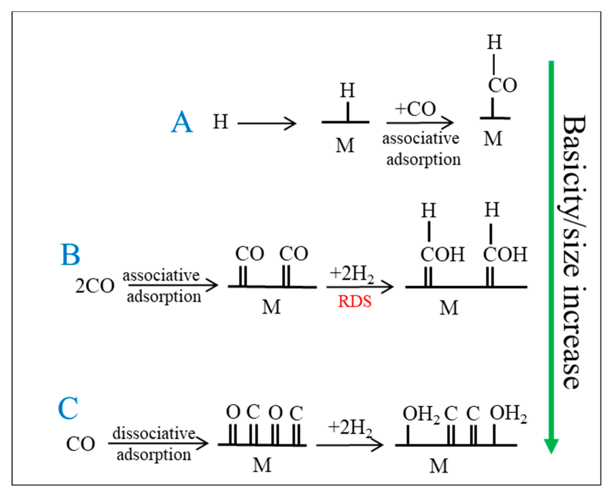
Figure 38 depicts the first few steps of the various proposed mechanisms of CO adsorption and emphasizes the back-donation of electron density from d-orbitals of FTS metals, regardless of orientation or crystal structure. Variations in back-donation are observed in IR spectroscopy in the vibrational modes and frequencies of adsorbed CO, such that the following configurations are observed: Route A: M-C≡O; Route B: M=C=O; and, Route C: M≡C-O [135]. The growing chain has two carbons that are attached to the metal (until the chain is terminated), Cx and Cy, which have sp2/sp3 like character where the chain growth on Cx is preferred, as displayed in Figure 35 and Figure 36, especially so in the case of the X2 configuration. Each of the three routes is shown in Figure 38:
Route A: Based on CO insertion, and perhaps only occurring with the iron carbide catalyst, this mechanism may proceed when H2 can readily adsorb onto the surface and dissociate, but when CO adsorbs molecularly, because scission of the CO bond without H*, is not kinetically favored [136]. The alkene takes on an L configuration, where chain growth at both Cx, and Cy is possible, as shown in Figure 35, Figure 36 and Figure 39. In that case, termination may produce internal olefins, branched paraffins (Figure 31), etc. This is not the primary pathway for any of the active metals used in FTS, such as cobalt or ruthenium; rather, it is only proposed to operate on the surface of unpromoted iron carbide (Figure 39, Figure 40, Figure 41 and Figure 42).
Route B: CO scission is not as difficult as in Route A, but CO still adsorbs in an associative manner, followed by being dissociated with the aid of H* on the active metal surface. An example of a possible mechanism stemming from this is the enol mechanism. The X2 configuration of the vinylic intermediate is dominant, providing well-ordered growth, decreasing the overall product diversity (Figure 43). This route is expected for cobalt and ruthenium catalysts.
Route C: Back donation from the metal is very strong and CO dissociates (Figure 44). Neither the L or X conformation of the vinylic intermediate exists as back donation is too strong, precluding its formation. This route is primarily expected for nickel catalysts.
This is a conceptual view, and complications arise given the heterogeneity of the active metal catalyst, and the proximity of the additives (promoters, active supports) to the active metal. This is all in the understanding that deviations in the expected product distribution may occur through reactor hold up, as previous research describes, such that secondary reactions may occur due to the re-adsorption of olefins, such as: reinsertion, hydrogenation, and isomerization [45,137,138,139,140,141,142,143,144,145,146,147,148,149].
While the product distribution for primary versus secondary products is still under debate [20,22,24,46,47,52,53,98,110,111,112,113,114,115,116,117,118,119,120,122,132,133], the findings from analytical work to date on various catalysts suggest the following points:
  • n-paraffins, 1-olefins, and linear alcohols are primary products. These products are observed through route B
  • n-paraffins, 1-olefins and linear alcohols come from the same active X2-configuration, as depicted in Figure 35 and Figure 36. Furthermore, 1-olefins and 2-olefins are, for the most part, not produced from each other (i.e., 2-olefins are not derived from 1-olefins and vice versa). Deviations are also possible with longer chained material through secondary reactions, especially under conditions where there is considerable reactor holdup. When X2 is the dominant configuration, all other products, including branched paraffins, 2-olefins, etc., likely come from secondary reactions.
In active iron carbide FTS catalysts, the back-donation of electron density directly influences the bonding configuration of the vinylic intermediate. Without the addition of alkali promoter, poor back-donation results, Route A is dominant, and CO dissociation is kinetically unfavorable at these conditions, as displayed in Figure 30 where the major products are light n-paraffins, methane, and isomerized hydrocarbons. Once a promoter is added, there is a localized effect on the metal (Figure 37), and both Routes B and C will occur, depending on the promoter’s capability to affect the electronic structure of iron carbide. The proximity of the promoter to the metal is likely a key factor in determining the extent to which each route occurs. However, given the capability of CO to bond in several different configurations, (e.g., linear, bent, and several distinct types of bridge bonded configurations), its bonding is much more complicated than that of the vinylic intermediate (Figure 36). As the promoter size/basicity or atomic ratio is increased, its capability to influence the metal is increased.
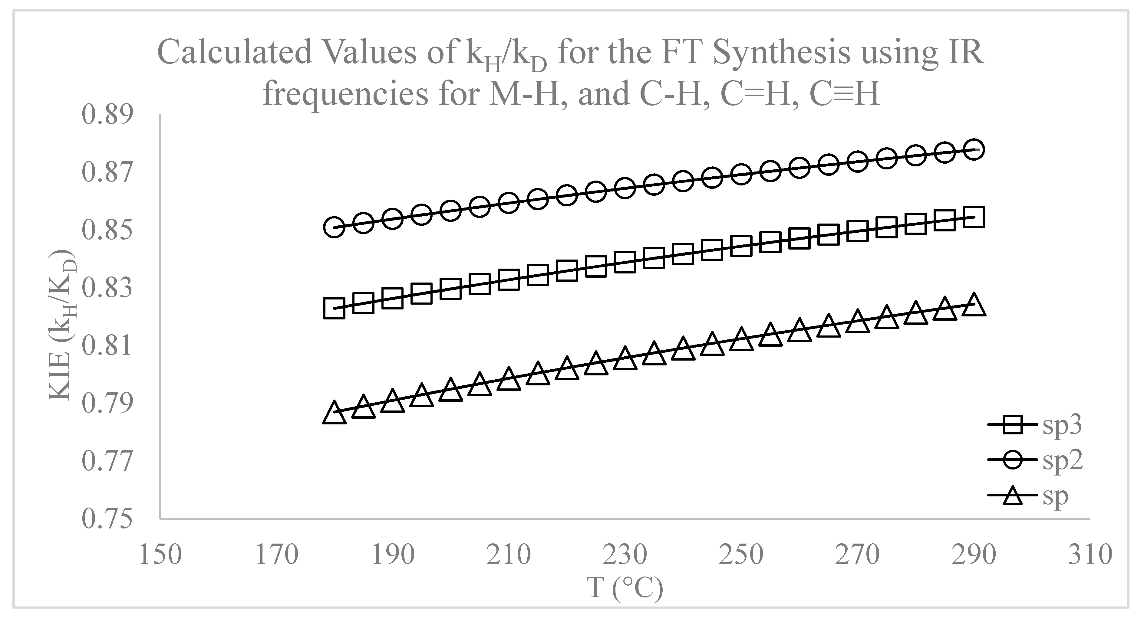
Simply put, there needs to be a balance on the active surface of the CO, H, and chain growth intermediates. This balance is maintained by how the active metal reacts with CO through its back donation of electron density. Evidence of this balance could be further strengthened by kinetic isotope effect (KIE) investigations for FTS, where a feed having an equimolar mixture of H2/D2 resulted in the H/D ratio for conversion being typically less than 1 (and closer to 0.85—i.e., deuterium converted to a greater extent than hydrogen [20,22,24,46,47,52,53,98,110,111,112,113,114,115,116,117,118,119,120,122,132,133,150]). If the rate determining step is through termination by the addition of H, where the H adsorbed on the metal is taken up by carbon (as theoretically predicted in Figure 45), then the expected value of the KIE should be less than unity. To bolster this viewpoint, the calculations were completed by Shafer et al. [118] using the average infrared (IR) stretching frequencies of the M-H (in the range of 1700–2250 cm−1) and C-H/C=H/C≡H. More isotopic work needs to be completed to better understand the KIE for FTS [20,22,24,46,47,52,53,98,110,111,112,113,114,115,116,117,118,119,120,122,132,133].
This concept, as simple as it is, could also explain why, in an FTS environment, the cobalt and ruthenium product distributions are so different from that of iron carbide.

4. Product Distribution

4.1. Iron Catalysts

4.1.1. Hydrocarbons

The most telling feature in the addition of a base (i.e., an alkali like potassium) is the correlation between the increase in the 1-olefin selectivity and the decrease in methane selectivity, as shown in Table 2. 1-olefin selectivity tended to increase with increasing promoter basicity/size with iron catalysts. However, the internal 2-olefins show independence from the influence of the promoter (Table 2). The 2-olefins, being independent from the promoter, provide a good indication of the localized effects of the alkali on the iron, as shown in Figure 37. That is, some iron carbide surface has good contact with the alkali, such that vinylic intermediates exhibit the X2 configuration (major products are linear alcohols, 1-olefins, and n-paraffins) and some patches on the surface lack promoter, resulting in vinylic intermediates that have more L character (major products are n-paraffins, monomethyl-paraffins).
Thermodynamic modeling of the catalyst independent of the FTS product distribution suggests that olefins and paraffins are the primary products [54,137,138,139,151]. Moreover, the influence of the promoter on the WGS rate, although it seems to increase with the alkali series, must also be considered, as it affects the partial pressures of H2, CO, H2O, and CO2 in the reactor and could alter their surface coverages [152,153,154,155,156]. Pendyala et al. demonstrated the importance of the alkali on the carburization rate [157]; they found that adding water resulted in a positive effect in CO conversion at 270 °C. This showed that even under more oxidizing conditions, adding water did not oxidize the catalyst, because the carburization rate was sufficiently high. Yet, at 230 °C, which slowed the carburization rate of the catalyst, the addition of water oxidized the iron carbides, and FTS activity was lost. Recent TPR-EXAFS/XANES investigations by Ribeiro et al. [35] and Li et al. [158] indicate that the addition of alkali promotes the carburization rate of iron catalysts.
The findings are in line with the idea that adding potassium increases the back-donation of electron density for better adsorption and dissociation of CO; moreover, improving the back donation of electron density to the adsorbed vinylic intermediate results in more control, narrowing the product distribution by lessening the ability for internal olefins and branched hydrocarbons to form. Figure 39 describes chain growth via this proposed Cx = Cy vinylic species. There has been good evidence that supports vinylic intermediates as chain propagators [118,159,160], which may also explain the capability of olefins to readsorb and potentially reincorporate into the growing chain.
In the current context, the authors are not considering secondary reactions, but rather the effect that the addition of promoter has on changing the electronic density of the active metal. This, in turn, may alter the prevailing pathway for the formation of primary products (Figure 38, Figure 39, Figure 40, Figure 41, Figure 42, Figure 43 and Figure 44). This idea could indicate two different routes for the production of alkenes (Figure 38, Figure 39 and Figure 42), or possibly two different active sites that solely depend on the electronic structure of the iron. Shi et al. noted an independence of the formation of the 2-alkenes from the 1-alkenes when carrying out H/D exchange [161,162]. This is an indication that the formation of internal alkenes (i.e., again, excluding secondary reactions) is likely on a different pathway than the one that produces 1-alkenes. Shultz proposed, as shown in Figure 46, how secondary olefins may be formed on a separate pathway from that of the primary olefin. The same independence is observed in Table 2 and Table 3 for the Group I alkali promoter series—the 1-olefins increase with the series, whereas no real trend is observed for the internal olefins. Instead of conceptualizing the differences in 1-olefin and internal olefin selectivities regarding different pathways per se, we emphasize that the differences stem from differences in energetics due to the location on the catalyst where the chain initiates. If, as displayed in Figure 37, the localized basicity that is due to the alkali is higher, then the 1-olefin selectivity would tend to increase. Moreover, if the basicity is higher in highly localized positions on the catalyst surface, then the internal olefin selectivity would be less sensitive to the alkali, as there would be significant surface available that is not in sufficient proximity to the alkali (i.e., where the internal olefin would form). This could explain the inverse relationship between the 1-olefin and internal olefins that has been observed from multiple runs across various the iron catalysts considered (Figure 28 and Figure 29).
Results herein (Figure 9, Figure 10, Figure 11, Figure 31, Figure 47 and Figure 48, Table 4 and Table 5) suggest that the predominant mechanism for branching depends on where on the surface of the catalyst the chain initiates. Several catalyst tests in a CSTR have probed the products formed from a variety of FTS catalyst series with iron (i.e., varying potassium atomic ratio, using different alkali metals, using an unpromoted catalyst, etc.) as summarized in Figure 8A, Figure 9, Figure 10, Figure 11, Figure 12 and Figure 13, Figure 16, Figure 20 and Figure 28, Figure 29, Figure 30 and Figure 31, as well as Table 2, Table 3 and Table 4). In each case, the selectivities of 2 and 3-methyl branched alkanes were the highest, followed by a decrease in the selectivity as the methyl was positioned closer to the central carbon (i.e., 4 methyl > 5 methyl > 6 methyl etc.). There is a pattern that was observed in the isomerized products, independent of potassium (Figure 10 and Figure 48), suggesting that these are the products of the FTS process and not secondary reactions. These patterns are obtained from the different methyl branched products that were observed for each carbon number, not by plotting the selectivity of isomerized products having a specific methyl position across a series of products [163].

4.1.2. Oxygenates

Iron (i.e., iron carbide, with or without alkali promoter) seems to be the only active FTS catalyst that produces oxygenates in addition to linear alcohols in noteworthy amounts. Acids, ketones, esters (only in trace molar carbon % in the oil phase), and aldehydes were all detected in the oil and aqueous phases of the products that are produced by iron catalysts (Figure 20 and Figure 30).
The largest change for the oxygenate distribution in the iron catalyst series is the difference between the unpromoted and promoted catalysts (Figure 49 and Figure 50). There is a clear deviation that is brought on just by alkali addition, where there is a notable drop in the percentage of the aldehyde and ketone with respect to the total oxygenates. Interestingly, the drop in percentage by these two functional groups is offset by a percentage increase in the alcohols with respect to the total oxygenates. The acid functional group slightly increased in percentage with respect to the total oxygenates, by the addition of the smaller alkali metals (Li, Na). However, as basicity/size of the promoter increases, the acid, like the ketone and aldehyde, decreases with respect to the total oxygenates. Essentially, the ketone and aldehyde could be viewed as materials that only desorb as partially dissociated CO, because of an inability for CO to fully dissociate. This depends on the ability of H2 to reach the growing chain, where termination proceeds through CO insertion.
K not only can promote oxygenated materials, like the alcohol, but if enough is present, then aldehydes can also be produced (Figure 20). This difference can be observed when comparing the K promoted iron catalyst (Figure 20) with unpromoted iron (Figure 31). Thus, multiple routes are occurring as K donates electron density to promote CO dissociation, limiting hydrogen. If enough potassium is added, then hydrogen is so limited that the probability for termination by CO increases, resulting in the formation of these aldehydes. Regardless, provided that identical conditions exist for the Group I series, as Figure 48 and Table 2 show, there appears to be a direct relationship between the promoter series and the % of oxygenates observed. The correlation can only be attributed to the promoted iron series catalysts, as shown in Figure 28.

4.1.3. ASF Factors

Typically, both the hydrocarbon and oxygenate values (Figure 51) trended inversely (although less so for K promoted and unpromoted iron catalysts) with CO conversion. Residence time influences the secondary reactions, which is more significant for promoted catalysts. The K and Na doped Fe catalysts, as displayed in Table 2 and Table 3, exhibited the greatest changes in oxygenate selectivity by changing the CO conversion. The Rb and Cs promoted Fe catalysts produced the largest carbon mole % and highest α values for oxygenated material. Unlike the use of K promoter (Figure 50, Table 2), where the selectivity of oxygenates is dependent upon CO conversion, the selectivity of oxygenates in Rb and Cs promoted Fe catalysts is independent of the CO conversion (Figure 49).

4.1.4. Manganese Supported Iron Catalysts

The work here agrees with the literature, where supports, such as manganese (Figure 30) for iron, promote higher fractions of the 1-olefin, suppressing the 2-olefins [164,165,166]. However, the promotion of the 1-olefin is much more significant with the Fe/Mn catalyst that is shown in Table 2. Additionally, though not shown, the FeMn series of catalysts run under the same conditions as the alkali promoted iron series, displayed similar rates of WGS activity as the potassium promoted iron catalyst.

4.2. Cobalt and Ruthenium

Cobalt and ruthenium are very similar in their product selectivities (Figure 52). Unlike the iron series, the hydrocarbon product distribution of cobalt and ruthenium is much more specific to the n-paraffin and 1-olefin. Platinum is typically used with cobalt primarily to facilitate the reduction of cobalt. However, with the addition of reduction promoters, such as platinum, methane production is slightly increased [151,167,168]. This is to be expected, because platinum in a reduced state is a d10 metal, like nickel, and it would exhibit similar electron back-donation capability; thus, CO that was adsorbed on platinum would exhibit similar structure, as observed on nickel, M≡C--O. The addition of the alkali on cobalt, as observed with iron, increases the adsorption of CO, again most likely due to the increased ability for the d-orbitals of cobalt to interact with the carbon-carbon π orbitals [169].
The first observation is the low selectivity of alcohols between the supported and unsupported cobalt catalysts. The low selectivity does not necessarily mean that the supports are directly involved in the synthesis of oxygenates, but that they influence their production. Ceria, like manganese and titania, is a partially reducible oxide, and unlike the silica and alumina, it has the potential for hydrogen spillover [170,171]. However, the spillover of hydrogen upon supports for cobalt, such as ceria, may create oxygen vacancy sites (or associated bridging OH groups) (Figure 53) through the removal of an oxygen atom in the support (or conversion of O to -OH groups), which changes the ceria from 4+ to 3+ (the underlined ceria atoms). This, in turn, has the potential to affect the product distribution in the FT process.
Gnanamani et al. [40] conducted a H2/D2 switching study to examine the isotope effect on oxygenated products that are produced from a Co/Ce catalyst. Results (Table 6) from the switch showed an overall decrease in the oxygenated materials; however, the oxygenated products returned to their original composition upon switching back to hydrogen. These results suggest that the metal-support interface plays a significant role in the formation of oxygenated materials. In this case, CO could react at defect-associated bridging OH groups on ceria to form formate, which acts as a molecularly adsorbed CO species that is transferred across the interface to terminate chains; or, termination may proceed by the direct addition of mobile OH groups from ceria. In order to produce oxygenates, one view is that termination proceeds by the addition of molecularly adsorbed CO [171]. In either case, ceria could influence the termination pathway across the metal-support interface, with the growing chain being on metallic cobalt. Masuku et al. [172] completed similar H2/D2 switching experiments with an alumina supported cobalt catalyst to show no specific deviation in the products (Table 6).
Though the product distribution is similar, cobalt that is supported on carbon (Figure 32) could react differently from metal oxide supported cobalt catalysts [38]. Carbon has surface oxygenate functional groups and it is not necessarily inert. This gives rise to the potential for these supports to interfere in the chain growth process via functionalized groups, and further work is needed to shed light on this aspect [59].

5. Conclusions

The intention of this paper is to provide a brief overview of the product distribution across several FTS catalysts. Specific product selectivities (fingerprint) in the oil phase are highly informative, such that, by solely observing the oil phase, catalyst properties can largely be uncovered. The fingerprint of iron (iron carbide) is more diverse than cobalt and ruthenium and the surface of iron carbide catalyst has been much more tunable. To maximize the efficiency of an FTS catalyst, a sustained balance between CO, H2, and chain growth intermediates must be maintained. If electron back-donation from the catalyst surface to the vinylic intermediate and CO is too weak, then the L configuration is dominant forming isomerized, non-alcohol oxygenates and high methane. If too strong, the vinylic intermediate (as does CO) dissociates too rapidly, such that methane production is high, and carbon deposits on the surface leading to coking. Both unbalanced routes occur at the cost of the overall process. As the fingerprint reveals clues to the catalyst, this work could serve as a starting point for future experiments that are aimed at tuning FTS catalysts.

Author Contributions

Analytical workup and manuscript primary writer, W.D.S.; Catalyst preparation, M.K.G., J.Y., C.M.M.; characterization, G.J., U.G., Manuscript writing and primary editor—G.J.; Reactor testing, M.K.G., J.Y., C.M.M.; project manager; B.H.D.

Funding

This research received no external funding.

Acknowledgments

Shafer would like thank Asbury University, and Chelsea Parsons for assisting in the editing. Masuku would like to acknowledge partial financial support from the National Research Foundation of South Africa (Grant Number: 113652). Jacobs would like to acknowledge UTSA, the State of Texas, and the STARs program for financial support. The opinions, findings, and conclusions or recommendations expressed in this publication are those of the authors. The funding bodies accept no liability in this regard. Gnanamani would like to thank CAER at the University of Kentucky, and the Commonwealth of Kentucky.

Conflicts of Interest

The authors have no conflict of interest.

Glossary

ASFAnderson-Schulz-Flory Plot
CSTRContinuously Stirred Tank Reactor
EIElectron Impact
FIDFlame Ionization Detector
FTSFischer–Tropsch Synthesis
GCGas Chromatograph
GHSVGas Hourly Space Velocity
HCHigh CO Conversion
H2/CO-Hydrogen to Carbon Monoxide Ratio
IWIIncipient Wetness Impregnation
LCLow CO Conversion
LODLimit of Detection
MSDMass Selective Detector
O/PTotal Olefin to Paraffin Ratio
RTRetention Time
SIMSingle Ion Monitoring
TCDThermal-conductivity Detector
WFWeight Fraction
WHSVWeight Hourly Space Velocity
VLEVapor Liquid Equilibrium

References

  1. Wilhelm, D.J.; Simbeck, D.R.; Karp, A.D.; Dickenson, R.L. Syngas production for gas-to-liquids applications: Technologies, issues and outlook. Fuel Process. Technol. 2001, 71, 139–148. [Google Scholar] [CrossRef]
  2. Wood, D.A.; Nwaoha, C.; Towler, B.F. Gas-to-liquids (GTL): A review of an industry offering several routes for monetizing natural gas. J. Nat. Gas Sci. Eng. 2012, 9, 196–208. [Google Scholar] [CrossRef]
  3. Jessop, P.G.; Subramaniam, B. Gas-Expanded Liquids. Chem. Rev. 2007, 107, 2666–2694. [Google Scholar] [CrossRef]
  4. Davis, B.H. Clean fuels from coal: The path to 1972. Prepr. Symp. Am. Chem. Soc. Div. Fuel Chem. 2003, 48, 141–143. [Google Scholar]
  5. Zhang, Y.; Davis, B.H. Indirect coal liquefaction—Where do we stand? Prepr. Am. Chem. Soc. Div. Pet. Chem. 1999, 44, 20–24. [Google Scholar]
  6. Whitehurst, D.D.; Mitchell, T.O.; Farcasiu, M. Coal Liquefaction: The Chemistry and Technology of Thermal Processes; Academic Press, Inc.: New York, NY, USA, 1980; 390p. [Google Scholar]
  7. Liu, Z.; Shi, S.; Li, Y. Coal liquefaction technologies—Development in China and challenges in chemical reaction engineering. Chem. Eng. Sci. 2010, 65, 12–17. [Google Scholar] [CrossRef]
  8. Horne, P.A.; Williams, P.T. Influence of temperature on the products from the flash pyrolysis of biomass. Fuel 1996, 75, 1051–1059. [Google Scholar] [CrossRef]
  9. Swanson, R.M.; Platonc, A.; Satrio, J.A.; Brown, R.C. Techno-economic analysis of biomass-to-liquids production based on gasification. Fuel 2010, 89, S11–S19. [Google Scholar] [CrossRef] [Green Version]
  10. Medrano, J.A.; Oliva, M.; Ruiz, J.; García, L.; Arauzo, J. Hydrogen from aqueous fraction of biomass pyrolysis liquids by catalytic steam reforming in fluidized bed. Energy 2011, 36, 2215–2224. [Google Scholar] [CrossRef]
  11. Higman, C.; van der Burgt, M. Gasification; Gulf Professional Publishing: Houston, TX, USA, 2008; pp. 1–456. [Google Scholar]
  12. Nikrityuk, P.A.; Meye, B. Gasification Processes: Modeling and Simulation; Wiley-VCH: New York, NY, USA, 2014; pp. 1–360. [Google Scholar]
  13. Jacobs, G.; Crawford, A.C.; Davis, B.H. Water-gas shift: Steady state isotope switching study of the water-gas shift reaction over Pt/ceria using in-situ DRIFTS. Catal. Lett. 2005, 100, 147–152. [Google Scholar] [CrossRef]
  14. Jacobs, G.; Crawford, A.; Williams, L.; Patterson, P.M.; Davis, B.H. Low temperature water-gas-shift: Comparison of thoria and ceria catalysts. Appl. Catal. A Gen. 2004, 267, 27–33. [Google Scholar] [CrossRef]
  15. Martinelli, M.; Jacobs, G.; Graham, U.M.; Shafer, W.D.; Cronauer, D.C.; Kropf, J.A.; Marshall, C.L.; Khalid, S.; Visconti, C.G.; Lietti, L.; et al. Water-gas-shift: Characterization and testing of nanoscale YSZ supported Pt catalysts. Appl. Catal. A Gen. 2015, 497, 184–197. [Google Scholar] [CrossRef]
  16. Fu, Q. Howard Saltsburg, Maria Flytzani-Stephanopoulos, Active Nonmetallic Au and Pt Species on Ceria-Based Water-Gas Shift Catalysts. Science 2003, 301, 935–938. [Google Scholar] [CrossRef] [PubMed]
  17. Scherzer, J.; Gruia, A.J. Hydrocracking Science and Technology; Marcell Dekker Inc.: New York, NY, USA, 1996. [Google Scholar]
  18. Fischer, F.; Tropsch, H. Synthesis of Petroleum at Atmospheric Pressure from Gasification Products of Coal. Brennstoff-Chemie 1926, 7, 97–104. [Google Scholar]
  19. Fischer, F.; Tropsch, H. Development of the Benzene Synthesis from Carbon Monoxide and Hydrogen at Atmospheric Pressure. Brennstoff-Chemie 1930, 11, 489–500. [Google Scholar]
  20. Yang, J.; Shafer, W.D.; Pendyala, V.R.R.; Jacobs, G.; Chen, D.; Holmen, A.; Davis, B.H. Fisher-Tropsch Synthesis: Using Deuterium as a Tool to Investigate Primary Product Distribution. Catal. Lett. 2014, 144, 524–530. [Google Scholar] [CrossRef]
  21. Shi, B.; Davis, B.H. Fischer–Tropsch synthesis: Accounting for chain-length related phenomena. Appl. Catal. A 2004, 277, 61–69. [Google Scholar] [CrossRef]
  22. Davis, B.H. Fischer–Tropsch synthesis: Current mechanism and futuristic needs. Fuel Proc. Technol. 2001, 71, 157–166. [Google Scholar] [CrossRef]
  23. Tuxen, A.; Carenco, S.; Chintapalli, M.; Chuang, C.; Escudero, C.; Pach, E.; Jiang, P.; Borondics, F.; Beberwyck, B.; Alivisatos, A.P.; et al. Size-Dependent Dissociation of Carbon Monoxide on Cobalt Nanoparticles. J. Am. Chem. Soc. 2013, 135, 2273–2278. [Google Scholar] [CrossRef]
  24. Qi, Y.; Yang, J.; Chen, D.; Holmen, A. Recent Progresses in Understanding of Co-Based Fischer–Tropsch Catalysis by Means of Transient Kinetic Studies and Theoretical Analysis. Catal. Lett. 2015, 145, 145–161. [Google Scholar] [CrossRef]
  25. Jacobs, G.; Davis, B.H. Applications of isotopic tracers in Fischer–Tropsch synthesis. Catal. Sci. Technol. 2014, 4, 3927–3944. [Google Scholar] [CrossRef]
  26. Shi, B.; Jacobs, G.; Sparks, D.E.; Davis, B.H. Fischer-Tropsch Synthesis: 14C Labeled 1-alkene conversion using supercritical conditions with Co/Al2O3. Fuel 2005, 84, 1093–1098. [Google Scholar] [CrossRef]
  27. Dry, M.E. The Fischer–Tropsch process: 1950–2000. Catal. Today 2002, 71, 227–241. [Google Scholar] [CrossRef]
  28. Enger, B.C.; Holmen, A. Nickel and Fischer-Tropsch Synthesis. Catal. Rev. 2012, 54, 437–488. [Google Scholar] [CrossRef]
  29. Milburn, D.R.; Chary, V.R.K.; Davis, B.H. Promoted iron Fischer-Tropsch catalysts: Characterization by nitrogen sorption. Appl. Catal. A Gen. 1996, 144, 121–132. [Google Scholar] [CrossRef]
  30. Luo, M.; Hamdeh, H.; Davis, B.H. Potassium promoted iron Fischer-Tropsch Synthesis catalyst activation study with Mossbauer spectroscopy. Prepr. Am. Chem. Soc. Div. Pet. Chem. 2007, 52, 73–76. [Google Scholar]
  31. Pendyala, V.R.R.; Jacobs, G.; Gnanamani, M.K.; Hu, Y.; MacLennan, A.; Davis, B.H. Selectivity control of Cu promoted iron-based Fischer-Tropsch catalyst by tuning the oxidation state of Cu to mimic K. Appl. Catal. A Gen. 2015, 495, 45–53. [Google Scholar] [CrossRef]
  32. Rachid, O.; Singleton, A.H.; Goodwin, J.G., Jr. Comparison of patented Co F–T catalysts using fixed-bed and slurry bubble column reactors. Appl. Catal. A Gen. 1999, 186, 129–144. [Google Scholar]
  33. Girardona, J.-S.; Gribovala, A.Co.; Gengembre, L.; Chernavskii, P.A.; Khodakov, A.Y. Optimization of the pretreatment procedure in the design of cobalt silica supported Fischer–Tropsch catalysts. Catal. Today 2005, 106, 161–165. [Google Scholar] [CrossRef]
  34. Jacobs, G.; Das, T.K.; Zhang, Y.; Li, J.; Racoillet, G.; Davis, B.H. Fischer–Tropsch synthesis: Support, loading, and promoter effects on the reducibility of cobalt catalysts. Appl. Catal. A Gen. 2002, 233, 263–281. [Google Scholar] [CrossRef]
  35. Ribeiro, M.C.; Jacobs, G.; Davis, B.H.; Cronauer, D.C.; Kropf, A.J.; Marshall, C.L. Fischer–Tropsch Synthesis: An In-Situ TPR-EXAFS/XANES Investigation of the Influence of Group I Alkali Promoters on the Local Atomic and Electronic Structure of Carburized Iron/Silica Catalysts. J. Phys. Chem. C 2010, 114, 7895–7903. [Google Scholar] [CrossRef]
  36. Jacobs, G.; Ji, Y.; Davis, B.H.; Cronauer, D.; Kropf, A.J.; Marshall, C.L. Fischer–Tropsch synthesis: Temperature programmed EXAFS/XANES investigation of the influence of support type, cobalt loading, and noble metal promoter addition to the reduction behavior of cobalt oxide particles. Appl. Catal. A 2007, 333, 177–191. [Google Scholar] [CrossRef]
  37. Wang, W.J.; Chen, Y.W. Influence of metal loading on the reducibility and hydrogenation activity of cobalt/alumina catalysts. Appl. Catal. 1991, 77, 223–233. [Google Scholar] [CrossRef]
  38. Luo, M.; Shafer, W.D.; Davis, B.H. Fischer–Tropsch Synthesis: Branched Paraffin Distribution for Potassium Promoted Iron Catalysts. Catal. Lett. 2014, 144, 1031–1041. [Google Scholar] [CrossRef]
  39. Davis, B.H. Technology Development for Iron and Cobalt Fischer–Tropsch Catalysts; Quarterly Report #1, Contract #DE-FC26-98FT40308; Department of Energy (DOE): Commonwealth of Kentucky, USA, 2002. [Google Scholar]
  40. Gnanamani, M.K.; Jacobs, G.; Graham, U.M.; Ribeiro, M.C.; Noronha, F.B.; Shafer, W.D.; Davis, B.H. Influence of carbide formation on oxygenates selectivity during Fischer-Tropsch synthesis over Ce-containing Co catalysts. Catal. Today 2016, 261, 40–47. [Google Scholar] [CrossRef]
  41. Ribeiro, M.C.; Gnanamani, M.K.; Rabelo-Neto, R.C.; Azevedo, I.R.; Pendyala, V.R.R.; Jacobs, G.; Davis, B.H.; Noronha, F.B. Fischer-Tropsch Synthesis: Studies on the effect of support reducibility on the selectivity to n-alcohols in Co/CeO2.MOy (M = Si, Mn, Cr) catalysts. Top. Catal. 2014, 57, 550–560. [Google Scholar] [CrossRef]
  42. Gnanamani, M.K.; Jacobs, G.; Shafer, W.D.; Ribeiro, M.C.; Pendyala, V.R.R.; Ma, W.; Davis, B.H. Fischer-Tropsch synthesis: Deuterium isotopic study for the formation of oxygenates over CeO2-supported Pt-Co catalysts. Catal. Commun. 2012, 25, 12–17. [Google Scholar] [CrossRef]
  43. Gaube, J.; Klein, H.F. Studies on the reaction mechanism of the Fischer–Tropsch synthesis on iron and cobalt. J. Mol. Catal. A 2008, 283, 60–68. [Google Scholar] [CrossRef]
  44. Van Santen, R.A.; Markvoort, A.J.; Ghouri, M.M.; Hilbers, P.A.J.; Hensen, E.J.M. Monomer Formation Model versus Chain Growth Model of the Fischer–Tropsch Reaction. J. Phys. Chem. C 2013, 117, 4488–4504. [Google Scholar] [CrossRef]
  45. Ojeda, M.; Li, A.; Nabar, R.; Nilekar, A.U.; Mavrikakis, M.; Iglesia, E. Kinetically Relevant Steps and H2/D2 Isotope Effects in Fischer−Tropsch Synthesis on Fe and Co Catalysts. J. Phys. Chem. C 2010, 114, 19761–19770. [Google Scholar] [CrossRef]
  46. Kummer, J.T.; Podgurski, H.H.; Spencer, W.B.; Emmett, P.H. Mechanism studies of the Fischer-Tropsch synthesis. The addition of radioactive alcohol. J. Am. Chem. Soc. 1951, 73, 564–569. [Google Scholar] [CrossRef]
  47. Kummer, J.T.; Dewitt, W.; Emmett, P.H. Some Mechanism Studies on the Fischer-Tropsch Synthesis Using C14. J. Am. Chem. Soc. 1948, 70, 3632–3643. [Google Scholar] [CrossRef]
  48. Storch, H.H.; Golumbic, N.; Anderson, R.B. The Fischer–Tropsch and Related Syntheses; Wiley: New York, NY, USA, 1951. [Google Scholar]
  49. Pichler, H.; Schulz, H. Neuere Erkenntnisse auf dem Gebiet der Synthese von Kohlenwasserstoffen aus CO und H2. Chem. Ing. Tech. 1970, 42, 1162–1174. [Google Scholar] [CrossRef]
  50. Luo, M.; Bao, S.; Keogh, R.A.; Sarkar, A.; Jacobs, G.; Davis, B.H. Fischer-Tropsch Synthesis: A Comparison of Iron and Cobalt Catalysts. In Proceedings of the AIChE 2006 National Meeting, SanFrancisco, CA, USA, 12–17 November 2006. [Google Scholar]
  51. Schulz, H. Principles of Olefin Selectivity in Fischer-Tropsch Synthesis on Iron and Cobalt Catalysts. In Fischer-Tropsch Synthesis, Catalysts, and Catalysis: Advances and Applications; Davis, B.H., Occelli, M.L., Eds.; CRC Press, Taylor & Francis Group: Boca Raton, FL, USA, 2015. [Google Scholar]
  52. Jennifer, N. Deuterium Enrichment and the Kinetic Isotope Effect during Ruthenium Catalyzed Fischer-Tropsch Synthesis. Online Theses and Dissertations, Eastern Kentucky University, Lexington, Kentucky, 2015; p. 408. [Google Scholar]
  53. Chakrabarti, D.; Gnanamani, M.K.; Shafer, W.D.; Ribeiro, M.C.; Sparks, D.E.; Prasad, V.; de Klerk, A.; Davis, B.H. Fischer–Tropsch Mechanism: 13C18O Tracer Studies on a Ceria–Silica Supported Cobalt Catalyst and a Doubly Promoted Iron Catalyst. Ind. Eng. Chem. Res. 2015, 54, 6438–6453. [Google Scholar] [CrossRef]
  54. Schulz, H. Principles of Fischer–Tropsch synthesis—Constraints on essential reactions ruling FT-selectivity. Catal. Today 2013, 214, 140–151. [Google Scholar] [CrossRef]
  55. Anderson, R.B.; Friedel, R.A.; Storch, H.H. Fischer-Tropsch Reaction Mechanism Involving Stepwise Growth of Carbon Chain. J. Chem. Phys. 1951, 19, 313. [Google Scholar] [CrossRef]
  56. Schulz, G.V. Über die Beziehung zwischen Reaktionsgeschwindigkeit und Zusammensetzung des Reaktionsproduktes bei Makropolymerisationsvorgängen. Z. Phys. Chem. 1935, 30, 379–398. [Google Scholar] [CrossRef]
  57. Flory, P.J. Molecular Size Distribution in Linear Condensation Polymers. J. Am. Chem. Soc. 1936, 58, 1877–1885. [Google Scholar] [CrossRef]
  58. Schliebs, B.; Gaube, J. The Influence of the Promoter K2CO3 in Iron Catalysts on the Carbon Number Distribution of Fischer-Tropsch Products. Ber. Der Bunsenges. Für Phys. Chem. 1985, 89, 68–73. [Google Scholar] [CrossRef]
  59. Graham, U.M.; Jacobs, G.; Gnanamani, M.K.; Lipka, S.M.; Shafer, W.D.; Swartz, C.R.; Jermwongratanachai, T.; Chen, R.; Rogers, F.; Davis, B.H. Fischer Tropsch synthesis: High oxygenate-selectivity of cobalt catalysts supported on hydrothermal carbons. ACS Catal. 2014, 4, 1662–1672. [Google Scholar] [CrossRef]
  60. Dictor, R.A.; Bell, A.T. Fischer-Tropsch synthesis over reduced and unreduced iron oxide catalysts. J. Catal. 1986, 97, 121–136. [Google Scholar] [CrossRef]
  61. Patzlaff, J.; Liu, Y.; Graffmann, C.; Gaube, J. Studies on product distributions of iron and cobalt catalyzed Fischer–Tropsch synthesis. Appl. Catal. A 1999, 186, 109. [Google Scholar] [CrossRef]
  62. Madon, R.J.; Taylor, W.F. Fischer-Tropsch synthesis on a precipitated iron catalyst. J. Catal. 1981, 69, 32–43. [Google Scholar] [CrossRef]
  63. Dictor, R.A.; Bell, A.T. Effects of potassium promotion on the activity and selectivity of iron Fischer-Tropsch catalysts. Ind. Eng. Chem. Proc. Des. Dev. 1983, 22, 97–103. [Google Scholar]
  64. Satterfield, C.N.; Huff, G.A.; Longwell, J.P. Product distribution from iron catalysts in Fischer-Tropsch slurry reactors. Ind. Eng. Chem. Process. Des. Dev. 1982, 21, 465–470. [Google Scholar] [CrossRef]
  65. Henrici-Olive, G.; Olive, S. The Fischer-Tropsch Synthesis: Molecular Weight Distribution of Primary Products and Reaction Mechanism. Angew. Chem. Int. Ed. Eng. 1976, 15, 136–141. [Google Scholar] [CrossRef]
  66. Huff, G.A., Jr.; Satterfield, C.N. Evidence for two chain growth probabilities on iron catalysts in the Fischer-Tropsch synthesis. J. Catal. 1984, 85, 370–379. [Google Scholar] [CrossRef]
  67. Donnelly, T.J.; Yates, I.C.; Satterfield, C.N. Analysis and prediction of product distributions of the Fischer-Tropsch synthesis. Energy Fuels 1988, 2, 734–739. [Google Scholar] [CrossRef]
  68. Herzog, K.; Gaube, J. Kinetic studies for elucidation of the promoter effect of alkali in Fischer-Tropsch iron catalysts. J. Catal. 1989, 115, 337–346. [Google Scholar] [CrossRef]
  69. Kuipers, E.W.; Vinkenburg, I.H.; Oosterbeek, H. Chain Length Dependence of α-Olefin Readsorption in Fischer-Tropsch Synthesis. J. Catal. 1995, 152, 137–146. [Google Scholar] [CrossRef]
  70. Bukur, B.D.; Mukesh, D.; Patel, S.A. Promoter effects on precipitated iron catalysts for Fischer-Tropsch synthesis. Ind. Eng. Chem. Res. 1990, 29, 194–204. [Google Scholar] [CrossRef]
  71. Masuku, C.M.; Hildebrandt, D.; Glasser, D. The role of vapour–liquid equilibrium in Fischer–Tropsch product distribution. Chem. Eng. Sci. 2011, 66, 6254–6263. [Google Scholar] [CrossRef]
  72. Satterfield, C.N.; Huff, G.A., Jr. Carbon number distribution of Fischer-Tropsch products formed on an iron catalyst in a slurry reactor. J. Catal. 1982, 73, 187–197. [Google Scholar] [CrossRef]
  73. Von Elbe, G. Internal Equilibria and Partial Vapor Pressures of Mixtures of Primary Normal Alcohols with Normal Paraffin Hydrocarbons. J. Chem. Phys. 1934, 2, 73–81. [Google Scholar] [CrossRef]
  74. Iglesia, E.; Reyes, S.C.; Madon, R.J. Transport-Enhanced a-Olefin Readsorption Pathways in Ru-Catalyzed Hydrocarbon Synthesis. J. Catal. 1991, 129, 238–256. [Google Scholar] [CrossRef]
  75. Davis, B.H. Fischer-Tropsch synthesis: relationship between iron catalyst composition and process variables. Catalysis Today 2003, 84, 83–98. [Google Scholar] [CrossRef]
  76. Zhang, C.H.; Yang, Y.; Teng, B.T.; Li, T.Z.; Zheng, H.Y.; Xiang, H.W.; Li, Y.W. Study of an iron-manganese Fischer–Tropsch synthesis catalyst promoted with copper. J. Catal. 2006, 237, 405–415. [Google Scholar] [CrossRef]
  77. Shi, B.; Davis, B.H. Fischer-Tropsch synthesis: The paraffin to olefin ratio as a function of carbon number. Catal. Today 2005, 106, 129–131. [Google Scholar] [CrossRef]
  78. Shi, B.; Wu, L.; Liao, Y.; Jin, C.; Montavon, A. Explanations of the formation of branched hydrocarbons during Fischer-Tropsch synthesis by alkylidene mechanism. Top. Catal. 2014, 57, 451–459. [Google Scholar] [CrossRef]
  79. Shi, B.; Davis, B.H. Fischer-Tropsch Synthesis: Evidence for Chain Initiation by Ethene and Ethanol for an Iron Catalyst. Top. Catal. 2003, 26, 157–161. [Google Scholar] [CrossRef]
  80. Gnanamani, M.K.; Keogh, R.A.; Shafer, W.D.; Shi, B.; Davis, B.H. Fischer–Tropsch synthesis: Deuterium labeled ethanol tracer studies on iron catalysts. Appl. Catal. A 2010, 385, 46–51. [Google Scholar] [CrossRef]
  81. Gnanamani, M.K.; Keogh, R.A.; Shafer, W.D.; Davis, B.H. Deutero-1-pentene tracer studies for iron and cobalt Fischer–Tropsch synthesis. Appl. Catal. A Gen. 2011, 393, 130–137. [Google Scholar] [CrossRef]
  82. Masuku, C.M.; Hildebrandt, D.; Glasser, D.; Davis, B.H. Steady-State Attainment Period for Fischer–Tropsch Products. Top. Catal. 2014, 57, 582–587. [Google Scholar] [CrossRef]
  83. Ao, M.; Pham, G.H.; Sunarso, J.; Tade, M.O.; Liu, S. Active Centers of Catalysts for Higher Alcohol Synthesis from Syngas: A Review. ACS Catal. 2018, 8, 7025–7050. [Google Scholar] [CrossRef]
  84. Wang, Y.; Davis, B.H. Fischer–Tropsch synthesis. Conversion of alcohols over iron oxide and iron carbide catalysts. Appl. Catal. A Gen. 1999, 180, 277–285. [Google Scholar] [CrossRef]
  85. Ngantsoue-Hoc, W.; Zhang, Y.; O’Brien, R.J.; Lou, M.; Davis, B.H. Fischer–Tropsch synthesis: Activity and selectivity for Group I alkali promoted iron-based catalysts. Appl. Catal. A Gen. 2002, 236, 77. [Google Scholar] [CrossRef]
  86. Espinoza, R.L.; Visagie, J.L.; van Berge, P.J.; Bolder, F.H. Catalysts. U.S. Patent 5,733,839, 31 March 1998. [Google Scholar]
  87. Yang, J.; Shafer, W.D.; Pendyala, V.R.R.; Jacobs, G.; Ma, W.; Chen, D.; Holmen, A.; Davis, B.H. Fischer-Tropsch synthesis: Deuterium kinetic isotopic effect for a 2.5%Ru/NaY catalysts. Top. Catal. 2014, 57, 508–517. [Google Scholar] [CrossRef]
  88. Deitz, W.A. Response Factors for Gas Chromatographic Analysis. J. Chromatogr. Sci. 1967, 5, 68–71. [Google Scholar] [CrossRef]
  89. Leveque, R.E. Determination of C3-C8 hydrocarbons in naphthas and reformates utilizing capillary column gas chromatography. Anal. Chem. 1967, 39, 1811–1818. [Google Scholar] [CrossRef]
  90. Ackman, R.G. The Flame lonization Detector: Further Comments on Molecular Breakdown and Fundamental Group Responses. J. Gas Chromatogr. 1968, 6, 497–5001. [Google Scholar] [CrossRef]
  91. Ackman, R.G. Fundamental Groups in the Response of Flame Ionization Detectors to Oxygenated Aliphatic Hydrocarbons. J. Gas Chromatogr. 1964, 2, 173. [Google Scholar] [CrossRef]
  92. Pendyala, V.R.R.; Jacobs, G.; Graham, U.M.; Shafer, W.D.; Martinelli, M.; Kong, L.; Davis, B.H. Fischer–Tropsch synthesis: Influence of acid treatment and preparation method on carbon nanotube supported ruthenium catalysts. Ind. Eng. Chem. Res. 2017, 56, 6408–6418. [Google Scholar] [CrossRef]
  93. Holm, T. Aspects of the mechanism of the flame ionization detector. J. Chromatogr. A 1999, 842, 221–227. [Google Scholar] [CrossRef]
  94. Down, R.D.; Lehr, J.H. (Eds.) Environmental Instrumentation and Analysis Handbook; John Wiley & Sons: Hoboken, NJ, USA, 2005. [Google Scholar]
  95. Noltingk, B.E. Measurement of Temperature and Chemical Composition: Jones’ Instrument Technology, 4th ed.; Butterworth-Heinemann: Oxford, UK, 2013; p. 192. [Google Scholar]
  96. Barry, E.F.; Rosie, D.M. Response prediction of the thermal conductivity detector with light carrier gases. J. Chromatogr. A 1971, 59, 269–279. [Google Scholar] [CrossRef]
  97. Heftmann, E. Chromatography: A Laboratory Handbook of Chromatographic and Electrophoretic Methods, 3rd edition. J. Chromatogr. Sci. 1978, 16, 15A. [Google Scholar]
  98. Pendyala, V.R.R.; Chakrabarti, D.; de Klerk, A.; Keogh, R.A.; Sparks, D.E.; Davis, B.H. 14C-Labeled Alcohol Tracer Study: Comparison of Reactivity of Alcohols over Cobalt and Ruthenium Fischer–Tropsch Catalysts. Top. Catal. 2015, 58, 343–349. [Google Scholar]
  99. Masuku, C.M.; Hildebrandt, D.; Glasser, D. Olefin pseudo-equilibrium in the Fischer–Tropsch reaction. Chem. Eng. J. 2012, 181, 667–676. [Google Scholar] [CrossRef]
  100. Kellner, C.S.; Bell, A.T. Evidence for H2/D2 Isotope Effects on Fischer-Tropsch Synthesis over Supported Ruthenium Catalysts. J. Catal. 1981, 67, 175–185. [Google Scholar] [CrossRef]
  101. Jacobs, G.; Ribeiro, M.C.; Ma, W.; Ji, Y.; Khalid, S.; Sumodjo, P.T.A.; Davis, B.H. Group 11 (Cu, Ag, Au) promotion of 15%Co/Al2O3 Fischer-Tropsch synthesis catalysts. Appl. Catal. A Gen. 2009, 361, 137–151. [Google Scholar] [CrossRef]
  102. Ma, W.; Jacobs, G.; Keogh, R.A.; Bukur, D.B.; Davis, B.H. Fischer-Tropsch synthesis: Effect of Pd, Pt, Re, and Ru noble metal promoters on the activity and selectivity of a 25%Co/Al2O3 catalyst. Appl. Catal. A Gen. 2012, 437–438, 1–9. [Google Scholar] [CrossRef]
  103. Eliseev, O.L.; Tsapkina, M.V.; Dement’eva, O.S. Promotion of cobalt catalysts for the Fischer-Tropsch synthesis with alkali metals. Kinet. Catal. 2013, 54, 207–212. [Google Scholar] [CrossRef]
  104. Gnanamani, M.K.; Ribeiro, M.C.; Ma, W.; Shafer, W.D.; Jacobs, G.; Graham, U.M.; Davis, B.H. Fischer-Tropsch synthesis: Metal-support interfacial contact governs oxygenates selectivity over CeO2 supported Pt-Co catalysts. Appl. Catal. A Gen. 2011, 393, 17–23. [Google Scholar] [CrossRef]
  105. Ribeiro, M.C.; Gnanamani, M.K.; Garcia, R.; Jacobs, G.; Rabelo-Neto, R.C.; Noronha, F.B.; Gomes, I.G.; Davis, B.H. Tailoring the product selectivity of Co/SiO2 Fischer-Tropsch synthesis catalysts by lanthanide doping. Catal. Today 2018. [Google Scholar] [CrossRef]
  106. Blyholder, G.; Allen, M.C. Infrared spectra and molecular orbital model for carbon monoxide adsorbed on metals. J. Am. Chem. Soc. 1969, 91, 3158–3162. [Google Scholar] [CrossRef]
  107. Blyholder, G. Molecular Orbital View of Chemisorbed Carbon Monoxide. J. Phys. Chem. 1964, 68, 2772–2777. [Google Scholar] [CrossRef]
  108. Belosludov, R.V.; Sakahara, S.; Yajima, K.; Takami, S.; Kubo, M.; Miyamoto, A. Combinatorial computational chemistry approach as a promising method for design of Fischer–Tropsch catalysts based on Fe and Co. Appl. Surf. Sci. 2002, 189, 245–252. [Google Scholar] [CrossRef]
  109. Hocking, R.K.; Hambley, T.W. Database Analysis of Transition Metal Carbonyl Bond Lengths: Insight into the Periodicity of ð Back-Bonding, ó Donation, and the Factors Affecting the Electronic Structure of the TM-CtO Moiety. Organometallics 2007, 26, 2815–2823. [Google Scholar] [CrossRef]
  110. Betta, R.A.D.; Shelef, M. Heterogeneous Methanation: Absence of H2-D2, Kinetic Isotope Effect on Ni, Ru, and Pt. J. Catal. 1977, 49, 383–385. [Google Scholar] [CrossRef]
  111. Shelef, M.; Betta, R.A.D. Reply to comments on heterogeneous methanation: Absence of H2/D2 kinetic isotope effect on Ni, Ru, and Pt. J. Catal. 1979, 60, 169–170. [Google Scholar] [CrossRef]
  112. Van Nisselrooij, P.F.M.T.; Luttikholt, J.A.M.; van Meerten, R.Z.C.; de Croon, M.H.J.M.; Coenen, J.W.E. Hydrogen/deuterium kinetic isotope effect in the methanation of carbon monoxide on a nickel-silica catalyst. Appl. Catal. 1983, 6, 271–281. [Google Scholar] [CrossRef]
  113. McKee, E.W. Interaction of hydrogen and carbon monoxide on platinum group metals. J. Catal. 1967, 8, 240–249. [Google Scholar] [CrossRef]
  114. Shafer, W.D.; Jacobs, G.; Davis, B.H. Fischer–Tropsch Synthesis: Investigation of the Partitioning of Dissociated H2 and D2 on Activated Cobalt Catalyst. ACS Catal. 2012, 2, 1452–1456. [Google Scholar] [CrossRef]
  115. Shafer, W.D.; Jacobs, G.; Selegue, J.P.; Davis, B.H. An Investigation of the Partitioning of Dissociated H2 and D2 on Activated Nickel Catalysts. Catal. Lett. 2013, 143, 1368–1373. [Google Scholar] [CrossRef]
  116. Shafer, W.D.; Pendyala, V.R.R.; Gnanamani, M.K.; Jacobs, G.; Selegue, J.P.; Hopps, S.D.; Thomas, G.A.; Davis, B.H. Isotopic Apportioning of Hydrogen/Deuterium on the Surface of an Activated Iron Carbide Catalyst. Catal. Lett. 2015, 145, 1683–1690. [Google Scholar] [CrossRef]
  117. Shafer, W.D.; Pendyala, V.R.R.; Jacobs, G.; Selegue, J.; Davis, B.H. Fischer-Tropsch Synthesis, Catalysts, and Catalysis: Advances and Applications; Davis, B.H., Occelli, M.L., Eds.; CRC Press, Taylor & Francis Group: Boca Raton, FL, USA, 2015. [Google Scholar]
  118. Shafer, W.D. Investigation into the Competitive Partitioning Of Dissociated H2 and D2 on Activated Fischer-Tropsch Catalysts. Ph.D. Theses, University of Kentucky, Lexington, Kentucky, 2015. [Google Scholar]
  119. Pendyala, V.R.R.; Shafer, W.D.; Jacobs, G.; Davis, B.H. Fischer-Tropsch synthesis: Effect of solvent on the H2-D2 isotopic exchange rate over an activated cobalt catalyst. Can. J. Chem. Eng. 2015, 94, 678–684. [Google Scholar] [CrossRef]
  120. Pendyala, V.V.R.R.; Shafer, W.D.; Jacobs, G.; Davis, B.H. Fischer-Tropsch synthesis: Effect of solvent on the H2-D2 isotopic exchange rate over an activated nickel catalyst. Catal. Today 2016, 270, 2–8. [Google Scholar] [CrossRef]
  121. Gnanamani, M.K.; Hamdeh, H.H.; Jacobs, G.; Shafer, W.D.; Sparks, D.E.; Davis, B.H. Fischer-Tropsch Synthesis: Activity and Selectivity of χ-Fe5C2 and θ-Fe3C Carbides. In Fischer-Tropsch Synthesis, Catalysts, and Catalysis: Advances and Applications; Davis, B.H., Occelli, M.L., Eds.; CRC Press, Taylor & Francis Group: Boca Raton, FL, USA, 2015. [Google Scholar]
  122. Raye, A.; Davis, B.H. Fischer-Tropsch Synthesis. Mechanism Studies Using Isotopes. Catalysis 1996, 12, 52–131. [Google Scholar]
  123. Salvi, N.; Belpassi, L.; Tarantelli, F. On the Dewar–Chatt–Duncanson Model for Catalytic Gold(I) Complexes. Chem. A Eur. J. 2010, 16, 7231–7240. [Google Scholar] [CrossRef]
  124. Weststrate, C.J.; van Helden, P.; van de Loosdrecht, J.; Niemantsverdriet, J.W. Elementary steps in Fischer-Tropsch synthesis: CO bond scission, CO oxidation and surface carbiding on Co(0001). Surf. Sci. 2016, 648, 60–66. [Google Scholar] [CrossRef]
  125. Yang, J.; Frøseth, V.; Chen, D.; Holmen, A. Particle size effect for cobalt Fischer–Tropsch catalysts based on in situ CO chemisorption. Surf. Sci. 2016, 648, 67–73. [Google Scholar] [CrossRef]
  126. Ozbek, M.O.; Niemantsverdriet, J.H. Niemantsverdriet Elementary reactions of CO and H2 on C-terminated χ-Fe5C2(0 0 1) surfaces. J. Catal. 2014, 317, 158–166. [Google Scholar] [CrossRef]
  127. Nabaho, D.; Niemantsverdriet, J.H.; Claeys, M.; van Steen, E. Hydrogen spillover in the Fischer–Tropsch synthesis: An analysis of platinum as a promoter for cobalt–alumina catalysts. Catal. Today 2016, 261, 17–27. [Google Scholar] [CrossRef]
  128. Bartholomew, C.H. Hydrogen adsorption on supported cobalt, iron, and nickel. Catal. Lett. 1990, 7, 27–51. [Google Scholar] [CrossRef]
  129. Borg, Ø.; Frøseth, V.; Stors˦ter, S.; Rytter, E.; Holmen, A. Fischer-Tropsch synthesis recent studies on the relation between the properties of supported cobalt catalysts and the activity and selectivity. Surf. Sci. Catal. 2007, 167, 117. [Google Scholar]
  130. Zhang, R.; Hao, X.; Yong, Y.; Li, Y. Investigation of acetylene addition to Fischer–Tropsch Synthesis. Catal. Commun. 2011, 12, 1146–1148. [Google Scholar] [CrossRef]
  131. Krishnamoorthy, S.; Li, A.; Iglesia, E. Pathways for CO2 Formation and Conversion during Fischer–Tropsch Synthesis on Iron-Based Catalysts. Catal. Lett. 2002, 80, 77–86. [Google Scholar] [CrossRef]
  132. Shi, B.; Davis, B.H. 13C-tracer study of the Fischer–Tropsch synthesis: Another interpretation. Catal. Today 2000, 58, 255–261. [Google Scholar] [CrossRef]
  133. Mann, B.E.; Turner, M.L.; Quyoum, R.; Marsih, N.; Maitlis, P.M. Demonstration by 13C NMR Spectroscopy of Regiospecific Carbon−Carbon Coupling during Fischer−Tropsch Probe Reactions. J. Am. Chem. Soc. 1999, 121, 6497–6498. [Google Scholar] [CrossRef]
  134. Davis, B.H. Fischer–Tropsch Synthesis: Reaction mechanisms for iron catalysts. Catal. Today 2009, 141, 25–33. [Google Scholar] [CrossRef]
  135. Bistoni, G.; Rampino, S.; Scafuri, N.; Ciancaleoni, G.; Zuccaccia, D.; Belpassi, L.; Tarantelli, F. How π back-donation quantitatively controls the CO stretching response in classical and non-classical metal carbonyl complexes. Chem. Sci. 2016, 7, 1174–1184. [Google Scholar] [CrossRef]
  136. Ojeda, M.; Nabar, R.; Nilekar, A.U.; Ishikawa, A.; Mavrikakis, M.; Iglesia, E. CO activation pathways and the mechanism of Fischer–Tropsch synthesis. J. Catal. 2010, 272, 287–297. [Google Scholar] [CrossRef]
  137. Schulz, H. Short history and present trends of Fischer–Tropsch synthesis. Appl Catal A Gen. 1999, 186, 3–12. [Google Scholar] [CrossRef]
  138. Kuipers, E.W.; Scheper, C.; Wilson, J.H.; Vinkenburg, I.H.; Oosterbeek, H. Non-ASF product distributions due to secondary reactions during Fischer–Tropsch synthesis. J. Catal. 1996, 158, 288–300. [Google Scholar] [CrossRef]
  139. Van der Laan, G.P.; Beenackers, A.A.C.M. Kinetics and Selectivity of the Fischer–Tropsch Synthesis: A Literature Review. Catal. Rev. 1999, 41, 255–318. [Google Scholar] [CrossRef]
  140. Madon, R.J.; Reyes, S.C.; Iglesia, E. Primary and secondary reaction pathways in ruthenium-catalyzed hydrocarbon synthesis. J. Phys. Chem. 1991, 95, 7795–7804. [Google Scholar] [CrossRef]
  141. Ji, Y.-Y.; Xiang, H.-W.; Yang, J.-L.; Xu, Y.-Y.; Li, Y.-W.; Zhong, B. Effect of reaction conditions on the product distribution during Fischer–Tropsch synthesis over an industrial Fe-Mn catalyst. Appl. Catal. A 2001, 214, 77–86. [Google Scholar] [CrossRef]
  142. Iglesia, E.; Soled, S.L.; Fiato, R.A. Fischer-Tropsch synthesis on cobalt and ruthenium. Metal dispersion and support effects on reaction rate and selectivity. J. Catal. 1992, 137, 212–224. [Google Scholar] [CrossRef]
  143. Novak, S.; Madon, R.J.; Suhl, H. Secondary effects in the Fischer-Tropsch synthesis. J. Catal. 1982, 77, 141–151. [Google Scholar] [CrossRef]
  144. Schulz, H.; Claeys, M. Reactions of α-olefins of different chain length added during Fischer–Tropsch synthesis on a cobalt catalyst in a slurry reactor. Appl. Catal. A 1999, 186, 71–90. [Google Scholar] [CrossRef]
  145. Kapteijn, F.; de Deugd, R.M.; Moulijn, J.A. Fischer–Tropsch synthesis using monolithic catalysts. Catal. Today 2005, 105, 350–356. [Google Scholar] [CrossRef]
  146. Soled, S.; Iglesia, E.; Fiato, R.A. Activity and selectivity control in iron catalyzed Fischer-Tropsch synthesis. Catal. Lett. 1990, 7, 271–280. [Google Scholar] [CrossRef]
  147. Bukur, D.B.; Nowicki, L.; Manne, R.K.; Lang, X.S. Activation Studies with a Precipitated Iron Catalyst for Fischer-Tropsch Synthesis: II. Reaction Studies. J. Catal. 1995, 155, 366–375. [Google Scholar] [CrossRef]
  148. Donnelly, T.J.; Satterfield, C.N. Product distributions of the Fischer-Tropsch synthesis on precipitated iron catalysts. Appl. Catal. 1989, 52, 93–114. [Google Scholar] [CrossRef]
  149. Tau, L.M.; Dabbagh, H.A.; Davis, B.H. Fischer-Tropsch synthesis: carbon-14 tracer study of alkene incorporation. Energy Fuels 1990, 4, 94–99. [Google Scholar] [CrossRef]
  150. Ma, W.; Shafer, W.D.; Martinelli, M.; Sparks, D.E.; Davis, B.H. Fischer-Tropsch synthesis: Using deuterium tracer coupled with kinetic approach to study the kinetic isotopic effects of iron, cobalt and ruthenium catalysts. Catal. Today 2019, in press. [Google Scholar] [CrossRef]
  151. Schulz, H. Comparing Fischer-Tropsch Synthesis on Iron- and Cobalt Catalysts: The dynamics of structure and function. Stud. Surf. Sci. Catal. 2007, 163, 177–199. [Google Scholar]
  152. Jacobs, G.; Ricote, S.; Patterson, P.M.; Graham, U.M.; Dozier, A.; Khalid, S.; Rhodus, E.; Davis, B.H.; Brookhaven National Laboratory. Low temperature water-gas shift: Examining the efficiency of Au as a promoter for ceria-based catalysts prepared by CVD of an Au precursor. Appl. Catal. A Gen. 2005, 292, 229–243. [Google Scholar] [CrossRef]
  153. Ricote, S.; Jacobs, G.; Milling, M.; Ji, Y.; Patterson, P.M.; Davis, B.H. Low temperature water-gas shift: Characterization and testing of binary mixed oxides of ceria and zirconia promoted with Pt. Appl. Catal. A Gen. 2006, 303, 35–47. [Google Scholar] [CrossRef]
  154. Jacobs, G.; Ricote, S.; Davis, B.H. Low temperature water-gas shift: Type and loading of metal impacts decomposition and hydrogen exchange rates of pseudo-stabilized formate over metal/ceria catalysts. Appl. Catal. A Gen. 2006, 302, 14–21. [Google Scholar] [CrossRef]
  155. Jacobs, G.; Graham, U.M.; Chenu, E.; Patterson, P.M.; Dozier, A.; Davis, B.H. Low temperature water-gas shift: Impact of Pt promoter loading on the partial reduction of ceria, and consequences for catalyst design. J. Catal. 2005, 229, 499–512. [Google Scholar] [CrossRef]
  156. Pendyala, V.R.R.; Jacobs, G.; Mohandas, J.C.; Luo, M.; Ma, W.; Gnanamani, M.K.; Davis, B.H. Fischer–Tropsch synthesis: Attempt to tune FTS and WGS by alkali promoting of iron catalysts. Appl. Catal. A Gen. 2010, 389, 131–139. [Google Scholar] [CrossRef]
  157. Pendyala, V.R.R.; Jacobs, G.; Mohandas, J.C.; Luo, M.; Hamdeh, H.H.; Ji, Y.; Ribeiro, M.C.; Davis, B.H. Fischer–Tropsch Synthesis: Effect of Water Over Iron-Based Catalysts. Catal. Lett. 2010, 140, 98–105. [Google Scholar] [CrossRef]
  158. Lia, J.; Cheng, X.; Zhang, C.; Chang, Q.; Wang, J.; Wang, X.; Lv, Z.; Dong, W.; Yang, Y.; Lia, Y. State Effect of alkalis on iron-based Fischer-Tropsch synthesis catalysts: Alkali-FeOx interaction, reduction, and catalytic performance. Appl. Catal. A Gen. 2016, 528, 131–141. [Google Scholar] [CrossRef]
  159. Lee, S.W.; Coulombe, S.; Glavincevski, B. Investigation of methods for determining aromatics in middle-distillate fuels. Energy Fuels 1990, 4, 20–33. [Google Scholar] [CrossRef]
  160. Tau, L.; Dabbagh, H.A.; Chawla, B.; Davis, B.H. Fischer-Tropsch synthesis with an iron catalyst: Incorporation of ethene into higher carbon number alkanes. Catal. Lett. 1990, 7, 141–150. [Google Scholar] [CrossRef]
  161. O’Brien, B.S.R.; Davis, S.B.B.H. Mechanism of the Isomerization of 1-Alkene during Iron-Catalyzed Fischer–Tropsch Synthesis. J. Catal. 2001, 199, 202–208. [Google Scholar]
  162. Shi, B.; Liao, Y.; Naumovitz, J.L. Formation of 2-alkenes as secondary products during Fischer–Tropsch synthesis. Appl. Catal. A Gen 2015, 490, 201–206. [Google Scholar] [CrossRef]
  163. Shi, B.; Chunfen, J. Inverse kinetic isotope effects and deuterium enrichment as a function of carbon number during formation of C–C bonds in cobalt catalyzed Fischer–Tropsch synthesis. J. Appl. Catal A Gen. 2011, 393, 178–183. [Google Scholar] [CrossRef]
  164. Van Dijk, W.L.; Niemantsverdriet, J.W.; Kraan, A.M.v.; van der Baan, H.S. Effects of Manganese Oxide and Sulphate on the Olefin Selectivity of Iron Catalysts in the Fischer Tropsch Reaction. Appl. Catal. 1982, 2, 273–288. [Google Scholar] [CrossRef]
  165. Kreitman, K.M.; Baerns, M.; Butt, J.B. Manganese-oxide-supported iron Fischer-Tropsch synthesis catalysts: Physical and catalytic characterization. J. Catal. 1987, 105, 319–334. [Google Scholar] [CrossRef]
  166. Ribeiro, M.C.; Jacobs, G.; Pendyala, R.; Davis, B.H.; Cronauer, D.C.; Kropf, A.J.; Marshall, C.L. Fischer-Tropsch Synthesis: Influence of Mn on the Carburization Rates and Activities of Fe-Based Catalysts by TPR-EXAFS/XANES and Catalyst Testing. J. Phys. Chem. C 2011, 115, 4783–4792. [Google Scholar] [CrossRef]
  167. Diehl, F.; Khodakov, A.Y. Promotion of Cobalt Fischer-Tropsch Catalysts with Noble Metals: A Review. Oil Gas Sci. Technol. 2009, 64, 11–24. [Google Scholar] [CrossRef]
  168. Hilmen, A.M.; Schanke, D.; Holmen, A. TPR study of the mechanism of rhenium promotion of alumina-supported cobalt Fischer-Tropsch catalysts. Catal. Lett. 1996, 38, 143–147. [Google Scholar] [CrossRef]
  169. Vada, S.; Hoff, A.; Ådnanes, E.; Schanke, D.; Holmen, A. Fischer-Tropsch synthesis on supported cobalt catalysts promoted by platinum and rhenium. Top. Catal. 1995, 2, 155–162. [Google Scholar] [CrossRef]
  170. Prins, R. Hydrogen Spillover. Facts and Fiction. Chem. Rev. 2012, 112, 2714–2738. [Google Scholar] [CrossRef]
  171. Karim, W.; Spreafico, C.; Kleibert, A.; Gobrecht, J.; VandeVondele, J.; Ekinci, Y.; van Bokhoven, J.A. Catalyst support effects on hydrogen spillover. Nature 2017, 541, 68–71. [Google Scholar] [CrossRef]
  172. Masuku, C.M.; Shafer, W.D.; Ma, W.; Gnanamani, M.K.; Jacobs, G.; Hildebrandt, D.; Glasser, D.; Davis, B.H. Variation of residence time with chain length for products in a slurry-phase Fischer–Tropsch reactor. J. Catal. 2012, 287, 93–101. [Google Scholar] [CrossRef]
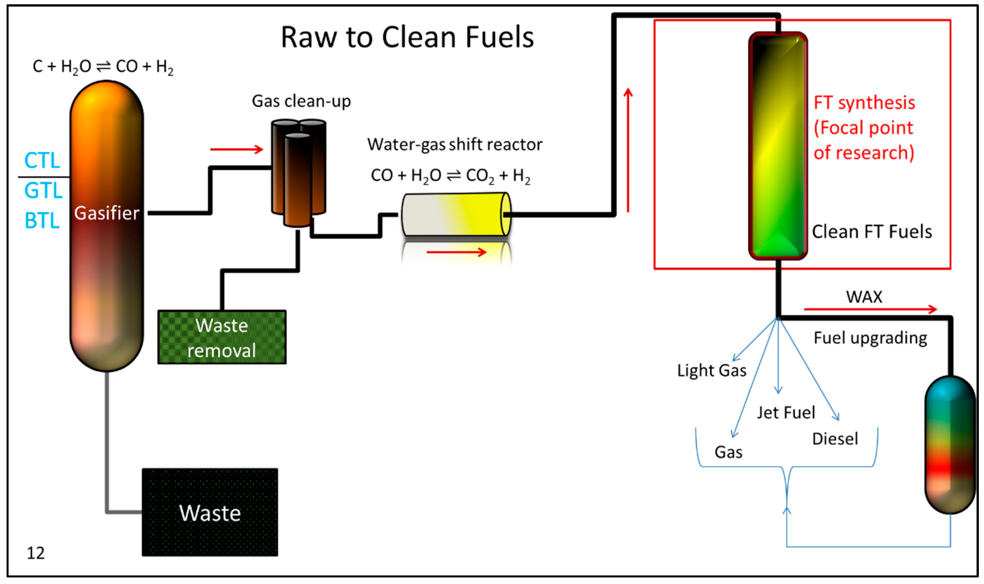
Figure 1. A simplified diagram of the Coal-to-Liquids (CTL), Gas-to-Liquids (GTL), and Biomass-to-Liquids (BTL) processes.
Catalysts 09 00259 g001
Figure 2. Deviations in the color of oils produced by Fischer–Tropsch synthesis (FTS).
Catalysts 09 00259 g002
Figure 3. A proposed FTS route based on the carbide mechanism.
Catalysts 09 00259 g003
Figure 4. A proposed FTS route based on the enol mechanism.
Catalysts 09 00259 g004
Figure 5. A proposed FTS route based on the CO insertion mechanism.
Catalysts 09 00259 g005
Figure 6. A general Anderson-Schulz-Flory (ASF) plot of the natural logarithm of the mole fraction for a cobalt, ruthenium, and iron FT product distribution. Fe-Cu/SiO2, 270 °C, 12.1 bar, weight hourly space velocity (WHSV) = 2, H2/CO = 0.7, 0.5%Pt/25%Co/Al2O3, Temperature 225 °C, Pressure = 27.6 bar, WHSV = 8, H2/CO = 2; and 1%Ru/Al2O3, Temperature 241 °C, Pressure = 29.9 bar, WHSV = 1.5, H2/CO = 2.
Catalysts 09 00259 g006
Figure 7. A distribution of products based upon α.
Catalysts 09 00259 g007
Figure 8. Typical flame ionization detector (FID) chromatographs for the products of the oil phase for Fe-Cu/SiO2, 270 °C, 12.1 bar, WHSV = 2, H2/CO = 0.7 (A), 0.5%Pt/25%Co/Al2O3, Temperature 225 °C, Pressure = 27.6 bar, WHSV = 8, H2/CO = 2 (B); and, 1%Ru/Al2O3, Temperature 241 °C, Pressure = 19.2 bar, WHSV = 1.5, H2/CO = 2 (C) FTS catalysts.
Catalysts 09 00259 g008
Figure 9. A chromatographic picture comparing different branching materials of specific carbon materials for a 0 K (i.e., no potassium promoter) active iron catalyst. This represents mixed oils from several iron runs where the oils were exposed to H2 at 0.68 bar for 5 min using Pt/C catalyst converting all olefinic materials to alkanes. All runs at 230 °C, 12.1 bar, 0.7 H2/CO with a WHSV = 2.
Catalysts 09 00259 g009
Figure 10. A chromatographic picture comparing different branched materials ranging from C11–C16. This is mixed oils from several iron runs where the oils were exposed to H2 at 0.68 bar for 5 min. using Pt/C catalyst converting all olefinic materials to alkanes. A is the linear alcohol, A* is where the alcohol is buried behind the 3-methyl branched paraffin. Otherwise, the order of methyl paraffins—starting from the n-paraffin going right to left; 3-methyl, 2-methyl, 4-methyl, 5-methyl, etc. All runs at 230 oC, 12.1 bar, 0.7 H2/CO, with a WHSV of 2.
Catalysts 09 00259 g010
Figure 11. Two separate fractions of oil from a mixture of a multitude of iron FTS runs, separated by silica gel with N2, and independently injected upon the MSD. The x-axis is retention time in minutes. The oxygenated chromatogram is only enlarged to display for identification purposes. These were not added to the overall analysis as the mole of carbon % were to small and difficult to quantify.
Catalysts 09 00259 g011
Figure 12. Two separate fractions of an iron FT oil separated by silica gel with N2 and independently injected upon the Agilent MSD. The x-axis is retention time in minutes. The oxygenated chromatogram is only enlarged for the purpose of identification. The green lines display where the oxygenated material peaks would elute in relationship to the main hydrocarbon peaks—if these materials were not first separated.
Catalysts 09 00259 g012
Figure 13. A chromatograph of the products produced with a lithium doped iron catalyst. The x-axis is retention time in minutes. Reaction Conditions: 270 °C, 12.1 bar, WHSV = 2, and H2/CO = 0.7.
Catalysts 09 00259 g013
Figure 14. A chromatographic picture of an oil product from the unsupported cobalt catalyst. The x-axis is retention time in minutes. Reaction Conditions: 220 °C, 27.3 bar, WHSV = 3, and H2/CO = 2.
Catalysts 09 00259 g014
Figure 15. A chromatographic picture of the oil for the alumina supported ruthenium catalyst. The x-axis is retention time in minutes. Reaction Conditions: 241 °C, 19.2 bar, WHSV = 1.5, and H2/CO = 2.
Catalysts 09 00259 g015
Figure 16. A chromatograph of the product produced with a rubidium doped iron catalyst. The x-axis is retention time in minutes. Reaction Conditions: 270 °C, 12.1 bar, WHSV = 2, and H2/CO = 0.7.
Catalysts 09 00259 g016
Figure 17. A chromatographic picture of a silica supported cobalt catalyst. The x-axis is retention time in minutes. Reaction Conditions: 220 °C, 27.6 bar, WHSV = 3, and H2/CO = 2.
Catalysts 09 00259 g017
Figure 18. A chromatographic picture of a titania supported ruthenium catalyst. The x-axis is retention time in minutes. Reaction Conditions: 220 °C, 19.3 bar, WHSV = 3, and H2/CO = 2.
Catalysts 09 00259 g018
Figure 19. A chromatographic picture of a ceria support cobalt catalyst. The x-axis is retention time in minutes. Reaction Conditions: 230 °C, 27.6 bar, WHSV = 0.5, and H2/CO = 2.
Catalysts 09 00259 g019
Figure 20. A chromatographic picture of potassium promoted iron catalyst. The x-axis is retention time in minutes. Reaction Conditions: 270 °C, 12.1 bar, WHSV = 2, and H2/CO = 0.7.
Catalysts 09 00259 g020
Figure 21. A chromatographic picture of a NaY supported ruthenium catalyst. The x-axis is retention time in minutes. Reaction Conditions: 220 °C, 19.2 bar, WHSV = 1.5, and H2/CO = 0.7.
Catalysts 09 00259 g021
Figure 22. An ASF plot of hydrocarbons and the relative oxygenates using a cesium doped iron catalyst, ranging C1 to C13 (oil, water, and wax combined) for a low CO conversion sample. Reaction Conditions: 270 °C, 12.1 bar, WHSV = 2, and H2/CO = 0.7.
Catalysts 09 00259 g022
Figure 23. An ASF plot of hydrocarbons and the relative oxygenates using a cesium doped iron catalyst, ranging C1 to C14 (oil, water, and wax combined) for a high CO conversion sample. Reaction Conditions: 270 °C, 12.1 bar, WHSV = 2, and H2/CO = 0.7.
Catalysts 09 00259 g023
Figure 24. A carbon distribution of the cobalt silica supported catalyst. Reaction Conditions: 220 °C, 27.6 bar, WHSV = 3, and H2/CO = 2.
Catalysts 09 00259 g024
Figure 25. A carbon distribution of the cobalt alumina supported catalyst. Reaction Conditions: 220 °C, 27.6 bar, WHSV = 5, and H2/CO = 2.
Catalysts 09 00259 g025
Figure 26. A carbon distribution of the titania supported ruthenium catalyst. Reaction Conditions: 220 °C, 19.2 bar, WHSV = 1.5, and H2/CO = 2.
Catalysts 09 00259 g026
Figure 27. A carbon distribution of the alumina supported ruthenium catalyst. Reaction Conditions: 220 °C, 19.2 bar, WHSV = 3, and H2/CO = 2.
Catalysts 09 00259 g027
Figure 28. A zoomed in chromatographic picture to display the difference in the main products fraction by the addition of different atomic ratios of K. “Low” is less than 2, (i.e., 2K100Fe), whereas “High” is greater than 2. This figure was built from 9 iron runs (with combinations of Cu, Si and K) catalyst runs that deviated one component while leaving the other two constant (e.g. K was varied while Si and Cu remained constant). The O/P ratio and the 1-olefin/2-olefin ratios only changed by varying K in the recipe. Furthermore, only when K ≥ 2, (2 and 5 atomic ratios) and K < 2 (0.5, 1, and 1, 25 atomic ratios) did these ratios change. Reaction Conditions were 270 °C, 12.1 bar, WHSV = 2, and H2/CO = 0.7.
Catalysts 09 00259 g028
Figure 29. The observed deviations in the 1-olefin/total olefin ratio, by altering the iron catalyst recipe, are most likely due only to the different amounts of potassium. Copper and silica do not affect the olefin ratio observed in the product selectivity. Reaction Conditions: 270 °C, 12.1 bar, WHSV = 2, and H2/CO = 0.7.
Catalysts 09 00259 g029
Figure 30. A chromatograph of the product produced with a manganese supported iron catalyst. The x-axis is retention time in minutes. Reaction Conditions: 270 °C, 12.1 bar, WHSV = 2, and H2/CO = 0.7.
Catalysts 09 00259 g030
Figure 31. A chromatographic picture of the oil for an 100% iron catalyst. The x-axis is retention time in minutes. Reaction Conditions: 270 °C, 12.1 bar, WHSV = 2, and H2/CO = 0.7.
Catalysts 09 00259 g031
Figure 32. A chromatographic picture of a carbon supported cobalt catalyst. The x-axis is retention time in minutes. Reaction conditions: 230 °C, 27.6 bar, WHSV = 0.5, and H2/CO = 2.
Catalysts 09 00259 g032
Figure 33. A mechanistic display of CO molecular addition through defect sites.
Catalysts 09 00259 g033
Figure 34. An atomic view of how the alkali could be affecting CO bonding.
Catalysts 09 00259 g034
Figure 35. Alkenes are known as π donors. Above represents the Dewar-Chatt-Duncanson model for the orbital orientation between the π orbitals of the alkene and the d orbitals from the metal. The electronic density of the metal will determine the hybridization of the carbon, where the planar olefin adduct (left structure) displays more sp2 hybridization for the carbon, and the metallocyclopropane exhibits more sp3 character.
Catalysts 09 00259 g035
Figure 36. This figure describes types of possible bonding for alkenes in the electronic effects brought on by the addition of a promoter (Ap), such as the Group I alkali series. As the size of the promoter increases, so does the iron surface area that it affects; as the alkali basicity increases, so does its ability to assist in back donation of electron density.
Catalysts 09 00259 g036
Figure 37. This figure describes types of possible bonding for CO depending on electronic effects that are caused by the addition of a promoter (Ap), such as the Group I alkali series. As observed with the vinylic intermediate, as the size of the promoter increases, so does the iron surface area that it affects. As the alkali basicity increases, so does its ability to assist in back donation of electron density.
Catalysts 09 00259 g037
Figure 38. A mechanistic starting point used to describe the effects induced by changes in size and basicity of the alkali promoter on the iron catalyst.
Catalysts 09 00259 g038
Figure 39. Proposed route A for the formation of several products observed in FTS, based on the CO insertion mechanism. Mechanistic routes for methane will be preferred when the back-donation of electron density from the metal is poor. This weak back donation does not easily allow for the vinylic intermediate to be formed or stabilized to the extent that is needed for chain growth. Furthermore, if the back-donation of electron density from the metal is too great (as with an activated nickel catalyst), then CO will dissociatively adsorb, and the vinylic intermediate, if formed, will be easily dissociated back to C1, to again prefer methane formation. Thus, the careful tuning of electron back donation from the metal must be maintained to achieve desired chain growth.
Catalysts 09 00259 g039
Figure 40. Taken from the previous route, where the vinylic intermediate takes on the L configuration, several products can be made because there is less controlled chain growth.
Catalysts 09 00259 g040
Figure 41. Proposed route A for the formation of several products observed in FTS, based on the CO insertion mechanism (Figure 38). This is the case where growth is somewhat controlled, but hydrogen is limited. However, given that growth occurs through CO insertion—alternative oxygenated materials could be made.
Catalysts 09 00259 g041
Figure 42. Proposed route A for the formation of several products observed in FTS, based on the CO insertion mechanism (Figure 38).
Catalysts 09 00259 g042
Figure 43. Proposed route B for the formation of several products observed in FTS, based on the enol mechanism.
Catalysts 09 00259 g043
Figure 44. Proposed route C for the formation of several products that are observed in FTS, based on the carbide mechanism. Here, methane and coke are formed, where the back-donation of electron density is too strong; thus, the strong back-donation of electron density precludes the formation of the vinylic chain growth intermediate. With metals like nickel, where hydrogen is not as suppressed, methane would be the main product. However, as hydrogen becomes suppressed due to the high dissociation rate of CO (because of the increased interaction), the surface becomes covered with carbonaceous deposits.
Catalysts 09 00259 g044
Figure 45. The calculated KIE value for FTS where H addition is the rate determining step, provided that the KIE for FTS was not significantly affected by hydrogen coverage. These calculations follow the ones that were performed by Shafer et al. [114,115,116,117,118]. Ratios are derived from the activation energy using IR stretching frequencies as the energy differences. The kH/kD values are taken from the average cm−1 for the M-H range (1700–2250 cm−1). The standard deviations are ±0.06.
Catalysts 09 00259 g045
Figure 46. A redrawn mechanism taken from Shultz et al. [51] describing a possible route for the formation of the 2-olefins from the 1-olefin though reversible hydrogen addition.
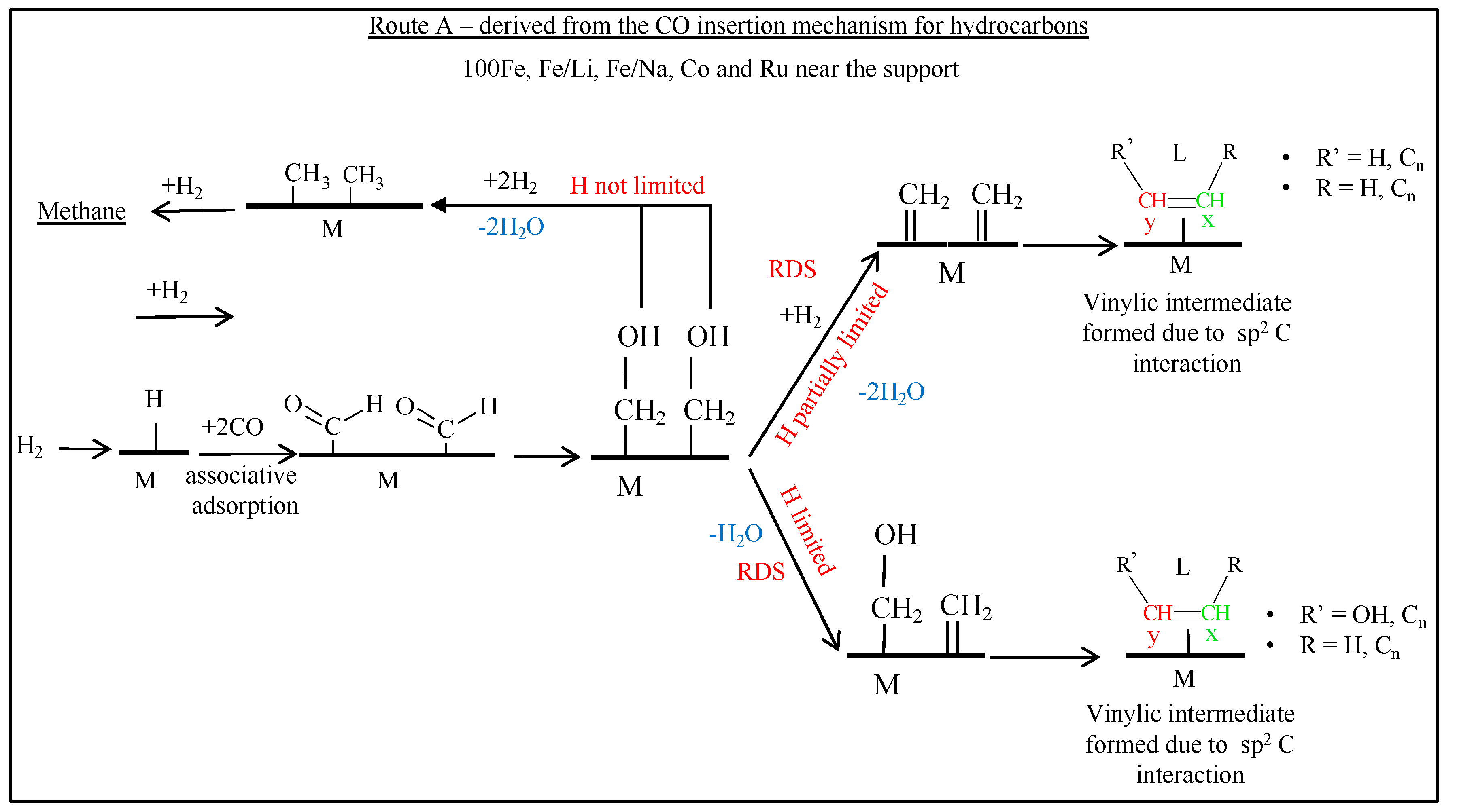
Catalysts 09 00259 g046
Figure 47. The molar carbon fraction of the total isomerized hydrocarbons per carbon number for the Group I series iron catalysts. As the basicity of the metal increases, allowing for more back donation, the overall branched material decreases. Reactor Conditions: 230 °C, 12.1 bar, WHSV = 2, and H2/CO = 0.7.
Catalysts 09 00259 g047
Figure 48. A graph of the single methyl branched products, arranged by carbon number, and not by the methyl group. This is a representation using a 2 K iron catalyst, where the oil was exposed to H2 at 0.68 bar for 5 min. All of the runs at 230 °C, 12.1 bar, 0.7 H2/CO with a WHSV of 2.
Catalysts 09 00259 g048
Figure 49. The % distribution of different oxygenated materials for each of the iron catalysts at low and high CO conversion. The percentage basis is taken as a % mole of carbon per functional group/%mole of C total oxygenates. Esters were observed, but they accounted for much less than one percent, with respect to the total oxygenates, and thus not added to this figure. Reactor conditions: 270 °C, 12.1 bar, WHSV = 2, and H2/CO = 0.7.
Catalysts 09 00259 g049
Figure 50. A product distribution of a K/Fe catalyst that shows the dependence of specific oxygenates with respect to the total oxygenates, on CO conversion. Reactor Conditions: 270 °C, 12.1 bar, WHSV = 2, H2/CO = 0.7.
Catalysts 09 00259 g050
Figure 51. Changes in the alpha vs. CO conversion for Group I promoted iron catalysts. Reactor Conditions: 270 °C, 12.1 bar, WHSV = 2, and H2/CO = 0.7.
Catalysts 09 00259 g051
Figure 52. This figure tracks the changes of the major products with time on stream. Reactor conditions: 220 °C, 19.3 bar, WHSV = 5, H2/CO = 2.
Catalysts 09 00259 g052
Figure 53. Bridging OH groups created in Ce due to addition of H2 during the reduction process; ceria is a well-known partially reducible oxide.
Catalysts 09 00259 g053
Table 1. Alpha (α) as compared across several FT synthesis catalysts.
Support/PromoterHydrocarbonsOxygenates
Cobalt
220 °C, 27.6 bar,
WHSV = 2–5
H2/CO = 2
Unsupported0.820.68
Alumina0.880.75
Silica0.860.79
Titania0.790.79
Carbon0.760.60
Ceria0.800.64
Ruthenium
220 °C, 19.2 bar,
WHSV = 1.5,
H2/CO = 2
Alumina0.780.63
Titania0.790.52
Silica0.800.70
NaY0.750.70
Iron at High CO conversion supported with 5.1 silica.
Reaction Conditions 270 °C,
12.1 bar,
WHSV = 2,
H2/CO = 0.7
Unsupported0.870.31
LiHC0.670.34
NaHC0.740.51
KHC0.780.60
RbHC0.740.64
CsHC0.720.66
Iron at Low CO conversion supported with 5.1 silica
270 °C, 12.1 bar,
WHSV = 2,
H2/CO = 0.7
Unsupported0.860.35
LiLC0.800.41
NaLC0.860.66
KLC0.820.74
RbLC0.920.69
CsLC0.890.73
Iron
270 °C, 12.1 bar, WHSV = 2,
H2/CO = 0.7
Manganese0.780.56
Hydrocarbons AlphaAverageStandard DeviationCoefficient of Variance
Cobalt0.820.045.49
Ruthenium0.780.023.02
Iron High CO0.750.078.93
Iron Low CO0.860.045.22
Oxygenates AlphaAverageStandard DeviationCoefficient of Variance
Cobalt0.710.0811.34
Ruthenium0.640.0913.42
Iron High CO0.510.1530.05
Iron Low CO0.600.1729.02
The alphas here do not include the heavy wax materials. Thus, to make an accurate comparison, the hydrocarbons were compared across the range C8–C15. The oxygenates varied based on the mole of carbon % observed and are primarily in the range of ~C4–C10. A few catalysts displayed product selectivities where the oxygenated materials may have been less than the limits of detection. Low CO conversion for the iron is ~25% and high conversion is 60%.
Table 2. Product Distribution in moles of C%.
Support/PromoterMethaneOxygenate Paraffin1-OlefinTrans-2-OlefinCis-2-OlefinO/PA/P
Cobalt
220 °C, 27.6 bar, WHSV = 2–5, H2/CO = 2
Unsupported42.201.4442.7910.562.330.680.160.02
Alumina14.982.5166.1013.121.002.300.200.03
Silica19.306.2753.3118.291.361.480.290.09
Titania19.402.9341.0330.263.572.810.610.05
Carbon18.0010.0758.387.893.262.400.180.13
Ceria28.8046.5911.928.812.041.840.311.14
Ruthenium
220 °C, 19.2 bar, WHSV = 1.5, H2/CO = 2
Alumina7.993.8559.9626.321.170.720.420.06
Titania8.363.4054.9024.644.903.800.530.05
Silica6.767.0551.5623.716.854.080.590.12
NaY7.532.2453.7025.137.114.300.600.04
Iron at High CO conversion supported with 5.1 silica.
Reaction Conditions 270 °C, 12.1 bar,
WHSV = 2, H2/CO = 0.7
unsupported46.260.2537.2212.902.331.040.190.00
LiHC12.462.5033.7140.196.924.221.110.05
NaHC12.873.8134.6944.272.511.831.020.08
KHC11.012.8430.3848.364.492.911.350.07
RbHC12.087.5229.0343.903.633.841.250.18
CsHC11.198.2325.4547.864.213.061.500.22
Iron at Low CO conversion supported with 5.1 silica
270 °C, 12.1 bar, WHSV = 2, H2/CO = 0.7
Unsupported17.660.5754.6618.814.523.780.370.01
LiLC13.415.0129.9945.113.732.751.190.12
NaLC10.433.1631.2445.195.514.481.320.08
KLC7.017.3927.1149.065.913.521.710.22
RbLC9.337.5328.6148.992.792.761.440.20
CsLC9.547.2625.3853.022.302.501.660.21
Iron
270 °C, 12.1 bar, WHSV = 2, H2/CO = 0.7
Manganese4.534.6919.9065.821.633.432.900.19
The data in Table 2 is normalized to compare only the oxygenates and four major peaks for FTS. CO2 and the isomerized/unknown products are not included in this selectivity. Furthermore, only active iron catalysts display CO2 above 1–2%, and isomerized products more than 5–10%. Lastly, the paraffin column does not include methane.
Table 3. Standard Deviations of the Products Based Upon the Change in CO Conversion.
AlphaProduct Distribution
CatalystHydrocarbonsOxygenatesOxygenate Paraffin1-OlefinTrans-2-OlefinCis-2-OlefinO/PA/PMethane
No Alkali0.010.030.237.904.181.541.940.130.0020.22
Li0.090.051.781.963.472.261.040.050.040.67
Na0.090.110.464.170.652.121.870.210.001.73
K0.030.093.225.140.491.000.430.260.102.83
Rb0.130.040.012.253.600.590.760.130.011.95
Cs0.120.050.691.223.651.340.390.110.011.17
The mole of carbon % of change in the product totals, and ASF plot alpha values by changing CO conversion; all numbers are displayed as standard deviations for values (provided in Table 1 and Table 2) at high CO conversions (~63%) and low CO conversion (~23%). CO conversion values are displayed in Figure 32. The orange colored numbers denote a loss in value by the decrease in conversion (i.e., the alpha value for the hydrocarbons for the lithium promoted iron catalysts displays an orange 0.9 standard deviation; the value for the alpha at low conversion was lower than the alpha value at high CO conversion). Reactor Conditions: 270 °C, 12.1 bar, WHSV = 2, and H2/CO = 0.7.
Table 4. The Percentage Difference in Methyl-branched to N-paraffins for a Range of K Promoted Iron Catalysts. Reactor Conditions: 230 °C, 12.1 bar, WHSV = 2, and H2/CO = 0.7.
% Total Mole of Carbon
Totals0%K2%K4%K6%K10%K
Ph79.8076.8678.1376.6062.79
2Me3.273.383.183.914.26
3Me3.533.283.033.994.37
4Me2.052.141.922.302.89
5Me1.341.201.721.482.10
6Me0.770.691.040.781.02
7Me0.340.300.540.32
Unseparated1.051.061.691.231.98
Total12.3510.9813.1214.0116.61
Table 5. A Comparison of the Isomerized to Normal Mole Fraction over a Series of Alkali Promoted Iron catalysts at low CO conversions (15–20%). Reactor Conditions: 270 °C, 12.1 bar, WHSV = 2, and H2/CO = 0.7.
Iso/Normal Mole Fraction
No Alkali0.21
Li0.17
Na0.16
Rb0.16
K0.16
Cs0.13
Table 6. The difference in product distribution on a Cobalt/Alumina catalyst when H2/CO is switched to D2/CO. Reactor Conditions: 220 °C, 19.3 bar, WHSV = 2, and H2/CO = 2.
Oil and WaxDH
Alcohol3.963.25
1-Olefin11.3010.21
Paraffin82.3484.40
Cis-Olefin0.930.95
Trans-Olefin1.461.19
Total Olefin13.6912.35