Article

Metal-Carbon-CNF Composites Obtained by Catalytic Pyrolysis of Urban Plastic Residues as Electro-Catalysts for the Reduction of CO2

Carbon Materials Research Group, Department of Inorganic Chemistry, Faculty of Sciences, University of Granada, Avenida de Fuentenueva, s/n, Granada ES18071, Spain
*
Author to whom correspondence should be addressed.
Catalysts 2018, 8(5), 198; https://doi.org/10.3390/catal8050198
Submission received: 26 March 2018 / Revised: 26 April 2018 / Accepted: 7 May 2018 / Published: 9 May 2018

Abstract

:
Metal–carbon–carbon nanofibers composites obtained by catalytic pyrolysis of urban plastic residues have been prepared using Fe, Co or Ni as pyrolitic catalysts. The composite materials have been fully characterized from a textural and chemical point of view. The proportion of carbon nanofibers and the final content of carbon phases depend on the used pyrolitic metal with Ni being the most active pyrolitic catalysts. The composites show the electro-catalyst activity in the CO2 reduction to hydrocarbons, favoring all the formation of C1 to C4 hydrocarbons. The tendency of this activity is in accordance with the apparent faradaic efficiencies and the linear sweep voltammetries. The cobalt-based composite shows high selectivity to C3 hydrocarbons within this group of compounds.

Graphical Abstract

1. Introduction

The increase of CO2 concentration in the atmosphere is thought to be one of the main causes of global climate change [1]. In particular, the CO2 emission from the use of fossil fuels contributes to the increasing concentration because it establishes a continuous net increase in the natural cycle of the tropospheric carbon.
There are different strategies proposed to control this issue [2] being the most extended the CO2 storage, and the CO2 transformation to other valuable products, together with the implementation of renewable energies.
On the other hand, renewable energy sources are supposed to be a replacement, but nowadays they are not producing the constant currents that fossil fuels provide. For this reason, the storage of surplus electrical energy produced during the peak production periods, and its release during peak demand periods, should be crucial. In this manner, extensive research effort has focused on battery storage [3]. However, battery manufacturing requires a lot of resources, reducing their contribution to controlling CO2 emission, and its life is relatively limited. Furthermore, recycling of their components is also a challenge.
One possible option to address the problem of temporary storing and local surplus of renewable energy is the electro-catalytic reduction of CO2 to hydrocarbons in water [4]. In this process, the water is split to provide the required hydrogen atoms, which react with CO2 to form hydrocarbons that can be used directly in the existing infrastructure of fuel transportation as well as in storing the renewable energy.
The direct electrochemical reduction of CO2 in aqueous solution has been typically studied with metal electrodes like Cu, Au, or Sn during the past few decades [5,6,7,8,9,10]. Copper electrodes have been found to be quite good in the reduction of CO2 to hydrocarbons, although the Faradaic efficiency was still low as a result of the dissociation of H2O to H2 [9]. More recently, metallic electrodes derived from corresponding metal oxides, like SnOx, seemed to show promising results in certain catalytic performance for CO2 reduction [11,12,13], and only a few transition-metal oxides such as TiO2, FeOx and Cu2O have been reported as potential electro-catalysts for this application [14].
Alternatively, the application of carbon materials in electro-catalytic CO2 reduction process is a plausible option, which has been tested with platinum catalysts supported on carbon nanotubes, carbon cloth or carbon black [15,16], and even metal-free carbons [17]. Centi et al. [15] showed for the first time the possibility of electro-catalytically converting CO2 to hydrocarbons with carbon chains >C5, and with product distributions which do not follow the Anderson–Schulz–Flory distribution model typical for Fischer-Tropsch synthesis. Li et al. [17] addressed nanoporous S-doped and S,N-codoped carbons as catalysts for electrochemical reduction CO2 to CO and CH4, where the negative charge on the pyridinic nitrogen groups promotes electron–proton transfer to CO2 leading to COOH* intermediates, which are further reduced to CO.
Carbon gels doped with transition metals have also shown activity in this reaction [18,19]. Although this CO2 reduction mechanism is still being studied [20], the products obtained in the direct electrochemical reduction of CO2 to hydrocarbons can achieve several carbon atoms [21]. Regarding the hydrocarbon selectivity, recently [22,23], a high selectivity to C3-hydrocarbons among the detected products has been reported using Co- and Fe-carbon electrodes. Moreover, Fe-carbon electrodes have shown a well-fitted linear correlation between the average crystal sizes of iron and the faradaic efficiencies: the smaller the crystal size, the higher the faradaic efficiency [23].
On the other hand, the large amounts of plastic residue is also a very important environmental problem, and the out-of-control combustion method should not be an option, because it would increase the CO2 atmospheric and cause other environmental pollution problems [24]. Within these materials, polyethylene (HDPE or LDPE) based plastic bags represent a significant proportion. There are several propositions for the recycling of plastic waste, as their transformation in fuels [25], the recovering of valuable components [26] of their transformation in carbon-based materials or composites [27]. However, the direct application of carbon-metal composites, obtained from real world plastic waste as CO2 electro-catalysts have not been reported yet. One important advantage of these composite materials as electro-catalysts compared to other proposed carbon based electro-catalysts is the low cost of the raw material since they can be obtained directly from the plastic waste. Therefore, with this proposal, we are focusing our actions on the CO2 problem twice, (i) researching in its electro-catalytic transformation to hydrocarbons; and (ii) proposing a way for the transformation of LDPE based residues in valuable products.
In the present work, we demonstrate the application of metal-carbon-carbon nanofibers composites obtained from real world plastic waste as promising electrodes in the electro-catalytic reduction of CO2 to hydrocarbons.

2. Results and Discussion

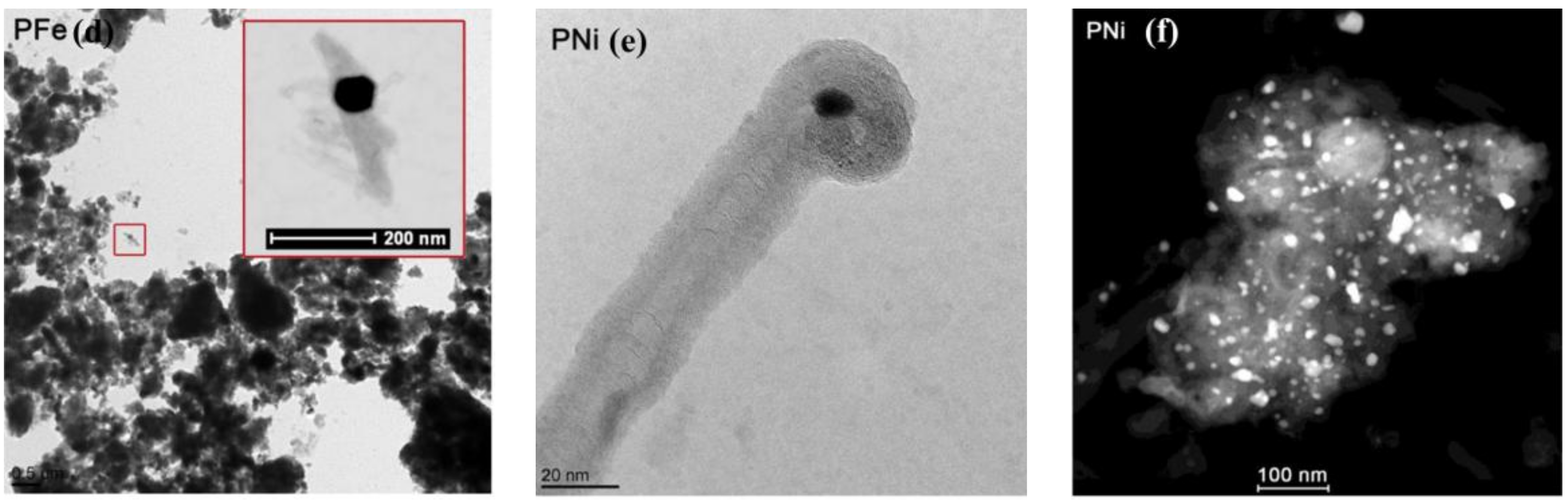
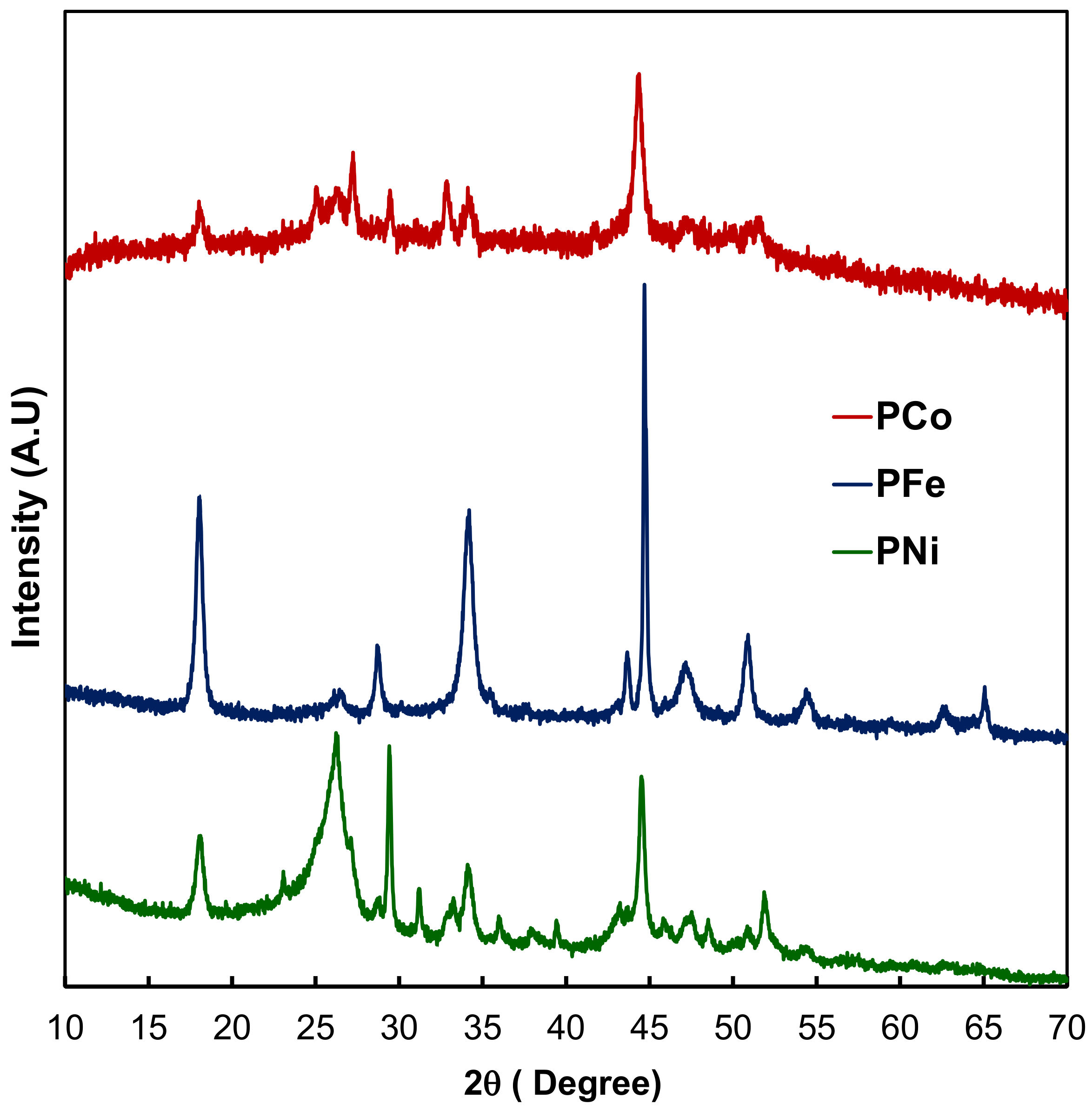
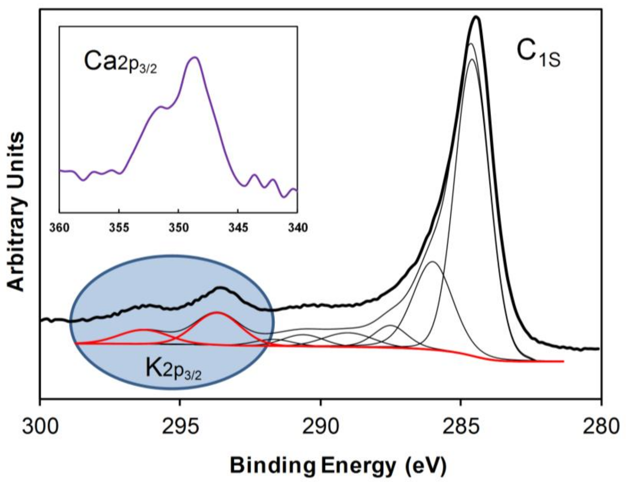
2.1. Textural and Chemical Characterization of the Composites

Table 1 summarizes the surface areas and pore volumes of the composites. These materials show apparent surface areas between 44 and 80 m2 g−1, and an extremely low microporosity, in fact, their N2 adsorption isotherms show typical type IV shapes.
SEM images of the composites are collected in Figure 1. The morphology consists in a mixture of carbon particles pseudo-flats, overlapped among them from where carbon-nanofibers (CNF) emerge. These CNF are clearly visible in sample PNi, where they are longer than in the other composites, although by HRTEM (Figure 2) the presence of CNF has been detected in all the samples being these CNF clearly hollow and maintaining the metal particle inside of them in most cases. Moreover, the main metal particles Fe, Co or Ni are very well dispersed throughout the carbon matrix (Figure 2), showing a wide range of sizes but all within the nanometric scale.
Regarding the metal chemical composition of the composites, Table 2 collects the ICP analysis of the samples. Firstly, it is observed that the content of the pyrolitic catalyst is not the same among the composites which denote a different catalytic behavior and, therefore, indicates different yield in carbon phases. In this line, composite PFe shows the highest metal loading, followed by PCo and lastly by PNi. Thus, small amounts of Fe, Co or Ni are present in all the samples which are in agreement with other studies where the metal content of commercial plastic bags have been analyzed [28]. Much more significant are the relatively high contents of Ca and K; these metals are typical additives of the commercial plastic bags to enhance stiffness and mechanical properties [29].
On the other site, Fe, Co, and Ni nanoparticles are mainly reduced in zero oxidation state (Figure 3) and situated in both of the carbon phases. This conclusion results from the corresponding XRD peaks that are clearly visible at 44.7°, 44.4° and 44.5° for Fe, Co, and Ni, respectively, while practically negligible amounts of these metals were detected by XPS (Table 3). Moreover, the aforementioned Fe, Co or Ni nanoparticles situated in the amorphous carbon phase are covered by graphitic clusters as it has been observed by HRTEM (Figure 2c), which is due to the fact that these metals are also the catalytic metals of graphitization [30,31].
Nevertheless, the case of Ca and K are very different, also between them: Ca particles are clearly Ca(II) forming part of Ca(OH)2; XRD peaks at 18 and 34° seem to confirm it (Figure 3) and the Ca2p3/2 XPS peak at 348.4 eV as well (Figure 4). However, K particles have not been detected by XRD, which means that its sizes should be lower than 4 nm approx., however, K(0) peaks have been clearly detected by XPS at 293.7 eV (Figure 4; only XPS spectra of PNi has been included in this Figure being the corresponding PCo and PFe XPS spectra very similar to this one). A plausible explanation would be that K(0) nanoclusters or atoms could be mainly inserted between the graphenic layers, as it is only in this situation that they could they keep the zero oxidation state after the final washing treatment of the samples. Finally, it should be noted that both data of chemical analysis, ICP and XPS are in good agreement: PNi is the composite with the lowest transition metal content obtained by ICP analysis and with the highest carbon content determined by XPS, while in the case of PFe, opposites occur. On the other hand, both K and Ca are homogeneously distributed throughout the composite since similar contents are obtained from both techniques.

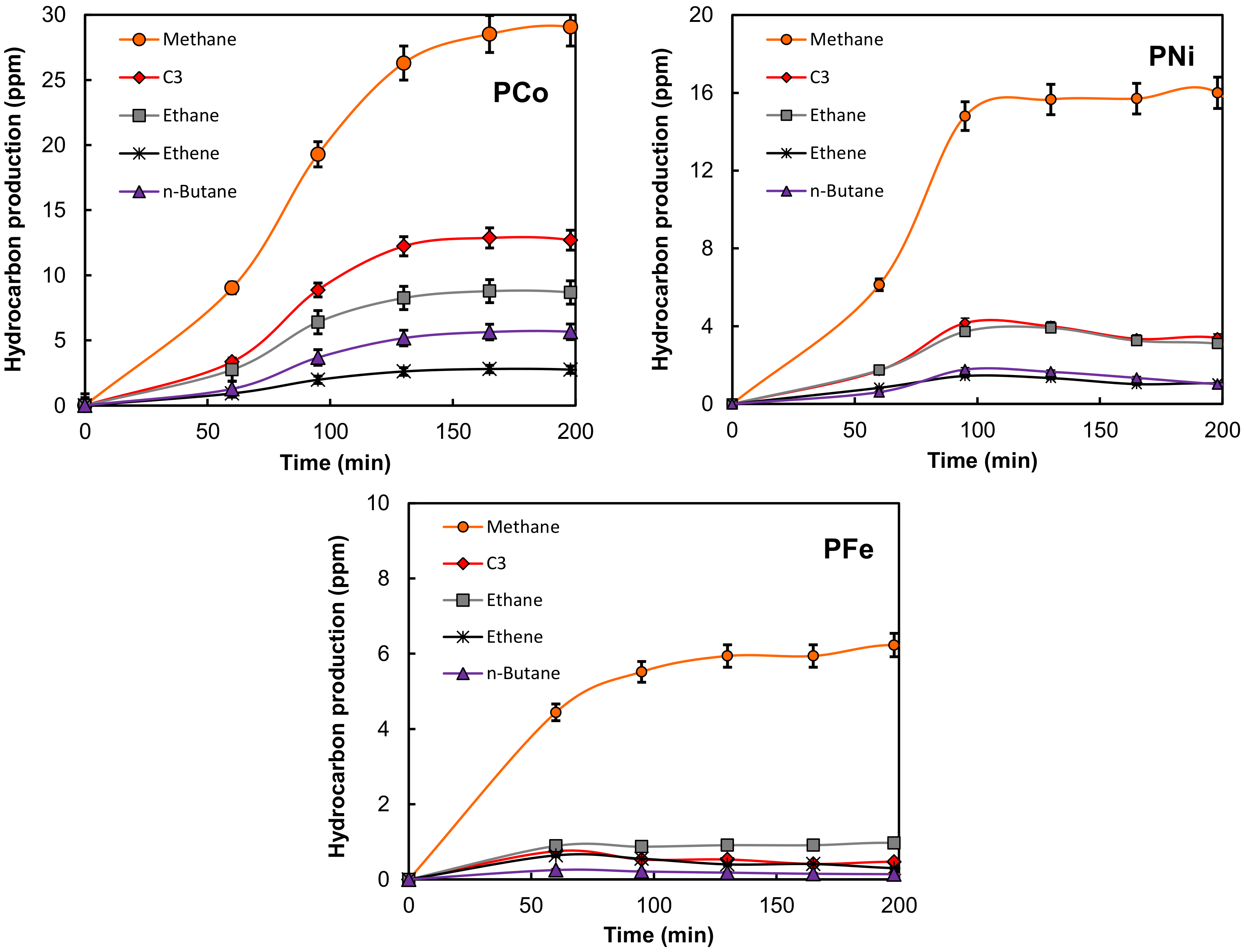
2.2. Electro-Reduction of CO2

The three composites were used as a cathode in the electro-catalytic reduction of CO2. A graphite sheet with dimensions of 50 mm × 8 mm was also tested as a blank cathode in the electro-catalytic reduction of CO2. The products analyzed in the gas phase of the reactor were the following: methane (CH4), ethane (C2H6), ethene (C2H4), propane (C3H8), propene (C3H6), propyne (C3H4) and n-butane (C4H10); Figure 5 shows the evolution of these compounds vs. the reaction time.
The molar production has also been described regarding C1, C2, C3 and C4 hydrocarbons, 1 to 4 being the number of carbon atoms in the molecules to simplify the discussion about the reaction selectivity. Nevertheless, methane was the major product in all of the cases, and minor amounts of other detected products (probably C4 isomers, or C5, hydrocarbons) have not been quantified. Thus, it is necessary to clarify that when an electrolyte free from dissolved CO2 was used (that is, carrying out the reaction under Ar-saturated solution), hydrocarbons, CO or CO2 were not detected in any cases. Similarly, in the presence of CO2 (normal experimental reaction conditions) and using only the pure graphite cathode, no hydrocarbons were detected. Regarding the molar production, although the surface area and pore volume of the composites were relatively low, the adsorption of a part of the product in the porous structure of the carbon phases could never be ruled out.
Data of the total molar productions of hydrocarbons in the reactor are collected in Figure 6; from this Figure, an adequate comparison of the electro-catalytic behavior of these composites is not straightforward because they do not present similar textural characteristics or metal contents. On the other side, we can see that the rate of hydrocarbon formation tends to decrease after ~100 min of reaction for PNi and PFe, and somewhat later for PCo. This type of catalytic behavior has been previously observed [22] and explained by a high formation of H2 and O2, which can provoke a dilution effect of the hydrocarbon formation in the gas phase of the reactor [32]. In any case, the following catalytic tendency can clearly be observed: PCo > PNi > PFe, which is in accordance with the apparent faradaic efficiencies calculated at 95 min of reaction time (Table 4). It is important to clarify that that only the detected hydrocarbons (nor H2 neither O2 formation) have been included in the faradaic efficiencies calculations. Faradaic efficiencies of this order have been previously obtained with Fe and Co doped carbon gels [22,23].
Therefore, the current findings demonstrate that all composites work as electro-catalysts in this reaction and that they are able to produce the CO2 transformation to at least C4 hydrocarbons. Moreover, the composite PCo exhibits high selectivity to C3 products (Figure 7) within this group of detected products, which is in accordance with a recent finding with another type of Co doped carbon materials [22]. On the other hand, although PNi is mainly selective to CH4, the amount of C3 produced was also higher than C2. Finally, composite PFe was the least active catalyst, and it was also least selective to long chain hydrocarbons, despite it having the highest metal loading (Table 2). As previously reported, this behavior is most likely due to its large mean crystal size of Fe (Table 4) [23]. In this line, it should be noted that this composite has a mean metal particle size much larger than the other samples. Figure 8 compares the LSV curves of CO2 reduction obtained with all the electro-catalysts. The strong increase of the current values at −1.65 V of the composite PFe denotes a low electro-catalytic capacity of this cathode in comparison with the other two samples.
Finally, all these cathodes were used in a second run of reaction, renovating the electrolyte and saturating with CO2; all of them again showed similar profiles from those collected in Figure 6. After drying, no significant weight differences were detected between the cathodes after the first and the second runs. Transition metal leaching in the liquid solutions was studied in all cases by ICP-OES; the detected metal concentrations in the liquids always being lower than 100 ppb.
This work shows that the preparation of CO2 electro-catalyst from real world plastic waste is achievable and although both the preparation method and the electro-chemical application still needs improvement and/or optimization for a real application, the obtained results are very promising. To our knowledge, the direct application of metal-carbon-CNF composites obtained from the real world plastic waste as CO2 electro-catalysts has not been reported yet.

3. Materials and Methods

Three different composites of metal-carbon-carbon nanofibers (-CNF) were prepared by a catalyzed pyrolysis of urban plastic residues which were thermally pre-treated in a closed reactor. These residues were plastic bags that were used in several well-known supermarkets in Spain, in which the polymer composition mainly consisted of low-density polyethylene (LDPE). Firstly, 10 g of the above-mentioned plastic bags were dissolved in 100 mL of o-xylene at 80 °C, and then 2 g of the catalysts precursor was added. The catalyst precursors were the corresponding hydroxides of Fe, Co and Ni, and the resulting mixture was stirred for 4 h. After that, the o-xylene was evaporated, and the solid was heat treated at 350 °C in a closed reactor (Parr Instrument, Moline, IL, USA) (reactor ref. A1828HC2) for four hours. Finally, the so pre-treated solid was pyrolised under N2 flow (300 mL min−1) at 900 °C. Before the characterization, the composites were washed with cool water several times. The obtained composites were named as PFe, PCo and PNi, being Fe, Co and Ni the pyrolitic catalyst, respectively.
The metal contents of the composites were determined by inductively coupled plasma optical emission spectrometry (ICP-OES) using an ICP-OES PerkinElmer OPTIMA 8300 spectrometer (PerkinElmer, Madrid, Spain).
The samples were texturally characterized by physical adsorption of nitrogen, scanning electron microscopy (SEM), high resolution transmission electron microscopy (HRTEM), and chemically characterized by X-ray diffraction (XRD) and X-ray photoelectron spectroscopy (XPS) Linear sweep voltammetries (LSV) were also carried out.
N2 adsorption was carried out at −196 °C. Prior to this measuring process, the samples were outgassed overnight at 110 °C under high vacuum (10−6 mbar). The BET equation was applied to the N2 adsorption data obtaining the apparent surface area, SBET. The Dubinin-Radushkevich (DR) equation was applied to the N2 adsorption data to obtain the corresponding micropore volume (W0) and micropore mean width (L0). Total pore volumes (V0.95) were calculated from N2 adsorption isotherms at −196 °C and at 0.95 relative pressure.
SEM was carried out using a Zeiss SUPRA40VP scanning electron microscope (Carl Zeiss AG, Oberkochen, Germany), equipped with a secondary electron detector, back-scatter electron detector and by using an X-Max 50 mm energy dispersive X-ray microanalysis system. All the samples were crushed before performing this analysis.
HRTEM was performed using a FEI Titan G2 60–300 microscope (FEI, Eindhoven, The Netherlands) with a high brightness electron gun (X-FEG) operated at 300 kV and equipped with a Cs image corrector (CEOS), and for analytical electron microscopy (AEM) a SUPER-X silicon-drift window-less EDX detector.
XRD analysis was carried out BRUKER D8 ADVANCE diffractometer (BRUKER, Rivas-Vaciamadrid, Spain) using CuKα radiation. JCPDS files were searched to assign the different diffraction lines observed. Diffraction patterns were recorded between 10° and 70° (2θ) with a step of 0.02° and a time per step of 96 s. The average crystal size was determined using the Scherrer equation.
XPS measurements of the metal-carbon-CNF composites were performed using a Physical Electronics ESCA 5701 (PHI, Chanhassen, MN, USA) equipped with a MgKα X-ray source (hυ = 1253.6 eV) operating at 12 kV and 10 mA and a hemispherical electron analyzer. The obtained binding energy (BE) values were referred to the C1s peak at 284.7 eV. A base pressure of 10−9 mbar was maintained during data acquisition. The survey and multi-region spectra were recorded at C1s, O1s, Fe2p, Co2p, Ni2p, K2p and Ca2p photoelectron peaks. Each spectral region was scanned enough times to obtain adequate signal-to-noise ratios. The spectra obtained after the background signal correction were fitted to Lorentzian and Gaussian curves to obtain the number of components, the position of each peak, and the peak areas.
Electro-catalytic reduction of CO2 to hydrocarbons was carried out in a three-electrode cell, working in batch mode at ambient temperature and pressure. The cell has 300 cm3 of total capacity. A Biologic VMP multichannel potentiostat (Bio-Logic Spain, Barcelona, Spain) was used to induce and control the electro-catalytic reaction by applying the selected potential differences over the electrodes. A platinum electrode was used as a counter electrode and Ag/AgCl as a reference electrode. The used electrolyte was 150 cm3 of CO2-saturated 0.1 M potassium bicarbonate aqueous solution. The setup was used in potentiostatic mode at −1.65 V, reproducing the voltage conditions of previous works [19]. Prior to the electro-catalytic CO2 reduction, the liquid phase was saturated through bubbling with CO2 for 3 h. After saturation, the pH of the solution was 6.7. The CO2 feed and exit lines were closed off and the reactor was operated in the batch mode. The amount of composite used in the cathode as electro-catalyst (working electrode) was 80 mg which was homogeneously pasted on both faces of a graphite sheet with dimensions of 50 mm × 8 mm. In the preparation of the cathode, the metal-carbon-CNF composite was mixed with the corresponding amount of polytetrafluoroethylene (PTFE) in a weight ratio of (80:7) using a PTFE (60%) water solution. All working electrodes were kept in 0.1 M potassium bicarbonate aqueous solution overnight before being used in the electro-reactor. The samples were also tested as electro-catalysts carrying out the reaction under Ar-saturated solution and, therefore, using electrolytes free of CO2.
The samples were also characterized by LSV (Bio-Logic Spain, Barcelona, Spain). The cathodic sweep analysis was conducted from the equilibrium electrode potential to negative electric potential of −2.0 V vs. Ag/AgCl, with a scan rate of 5 mV s−1, using the same experimental conditions and reactor set-up for the electro-catalytic reduction of CO2.
The hydrocarbons produced by the electro-chemical reduction of CO2 were analyzed from the gas phase using a gas chromatograph (GC) (Bruker Española, Rivas-Vaciamadrid, Spain), where the gases were directly injected into the GC column using a gas recirculating pump for low flows. The GC (carrier gas: He, column: Chrompack Poraplot Q, 50 m × 0.53 mm) was equipped with a FID and TCD detectors. The distribution of gaseous products can be expressed in terms of the carbon selectivity as the amount of carbon atoms (from CO2) in a specific product relative to the total amount of carbon atoms in the detected hydrocarbons.
S C i ( % ) = i n C i i i n C i × 100 %
Here nCi represents the mol of product Ci, and i the number of carbon atoms in that product.
The liquid phase was also analyzed by Headspace Gas Chromatography-Mass Spectrometry using another GC equipped with a HP-INNOWax 30 m × 0.25 mm × 0.25 µm column, which was coupled to a MS-Triple quadrupole. The presence of carboxylic acids or alcohols of one to four carbon atoms were not detected.

4. Conclusions

Metal-carbon-CNF composites have been obtained from the urban plastic waste. The amount and type of carbon nanofibers and final carbon contents depend on the pyrolitic used metal: Fe, Co or Ni. Ni catalysts yield the major amount of CNF and carbon phases in the composites. On the other hand, significant contents of Ca and K are also present in the composites, however, while Ca is forming part of Ca(OH)2, K atoms could be embedded inside the carbon phases as K metallic. The composites have been tested as electro-catalyst in the CO2 reduction to hydrocarbons, and all of them promoted the formation of C1 to C4 hydrocarbons with different activity: PCo > PNi > PFe, which is in accordance with the apparent faradaic efficiencies. It should be highlighted that PCo shows high selectivity to C3 products within this group of compounds.

Author Contributions

A.F.P.-C. and F.C.-M. conceived and designed the experiments; J.C.-Q. and A.E. performed the experiments; A.F.P.-C., F.C.-M. and F.J.M.-H. analyzed the data; A.F.P.-C. and F.C.-M. wrote the paper.

Acknowledgments

This research is supported by the FEDER and Spanish projects CTQ2013-44789-R (MINECO) and P12-RNM-2892 (Junta de Andalucía). J.C.-Q. is grateful to the Junta de Andalucía for her research contract (P12-RNM-2892). A.E. acknowledges a predoctoral fellowship from Erasmus Mundus, Al-Idrissi, programme.

Conflicts of Interest

The authors declare no conflict of interest.

References

  1. World Meteorological Organization. Available online: http://www.wmo.int/ (accessed on 1 May 2018).
  2. Centi, G.; Perathoner, S. Opportunities and prospects in the chemical recycling of carbon dioxide to fuels. Catal. Today 2009, 148, 191–205. [Google Scholar] [CrossRef]
  3. Stevenson, K. The origin, development, and future of the lithium-ion battery. J. Solid State Electrochem. 2012, 16, 2017–2018. [Google Scholar] [CrossRef]
  4. Bevilacqua, M.; Filippi, J.; Miller, H.A.; Vizza, F. Recent technological progress in CO2 electroreduction to fuels and energy carriers in aqueous environments. Energy Technol. 2015, 3, 197–210. [Google Scholar] [CrossRef]
  5. Hori, Y.; Murata, A. Electrochemical evidence of intermediate formation of adsorbed CO in cathodic reduction of CO2 at a nickel electrode. Electrochim. Acta 1990, 35, 1777–1780. [Google Scholar] [CrossRef]
  6. Hori, Y.; Murata, A.; Takahashi, R. Formation of hydrocarbons in the electrochemical reduction of carbon dioxide at a copper electrode in aqueous solution. J. Chem. Soc. Faraday Trans. 1989, 85, 2309–2326. [Google Scholar] [CrossRef]
  7. Hori, Y.; Wakebe, H.; Tsukamoto, T.; Koga, O. Electrocatalytic process of CO selectivity in electrochemical reduction of CO2 at metal electrodes in aqueous media. Electrochim. Acta 1994, 39, 1833–1839. [Google Scholar] [CrossRef]
  8. Jitaru, M.; Lowy, D.A.; Toma, M.; Toma, B.C.; Oniciu, L. Electrochemical reduction of carbon dioxide on flat metallic cathodes. J. Appl. Electrochem. 1997, 27, 875–889. [Google Scholar] [CrossRef]
  9. Gattrell, M.; Gupta, N.; Co, A. A review of the aqueous electrochemical reduction of CO2 to hydrocarbons at copper. J. Electroanal. Chem. 2006, 594, 1–19. [Google Scholar] [CrossRef]
  10. Chaplin, R.P.S.; Wragg, A.A. Effects of process conditions and electrode material on reaction pathways for carbon dioxide electroreduction with particular reference to formate formation. J. Appl. Electrochem. 2003, 33, 1107–1123. [Google Scholar] [CrossRef]
  11. Zhang, R.; Lv, W.; Li, G.; Lei, L. Electrochemical reduction of CO2 on SnO2/nitrogen-doped multiwalled carbon nanotubes composites in KHCO3 aqueous solution. Mater. Lett. 2015, 141, 63–66. [Google Scholar] [CrossRef]
  12. Li, F.; Chen, L.; Knowles, G.P.; MacFarlane, D.R.; Zhang, J. Hierarchical Mesoporous SnO2 Nanosheets on Carbon Cloth: A Robust and Flexible Electrocatalyst for CO2 Reduction with High Efficiency and Selectivity. Angew. Chem. Int. Ed. 2017, 56, 505–509. [Google Scholar] [CrossRef] [PubMed]
  13. Bashir, S.; Hossain, S.; Rahman, S.u.; Ahmed, S.; Amir, A.; Hossain, M.M. Electrocatalytic reduction of carbon dioxide on SnO2/MWCNT in aqueous electrolyte solution. J. CO2 Util. 2016, 16, 346–353. [Google Scholar] [CrossRef]
  14. Zhu, D.D.; Liu, J.L.; Qiao, S.Z. Recent Advances in Inorganic Heterogeneous Electrocatalysts for Reduction of Carbon Dioxide. Adv. Mater. 2016, 28, 3423–3452. [Google Scholar] [CrossRef] [PubMed]
  15. Centi, G.; Perathoner, S.; Wine, G.; Gangeri, M. Electrocatalytic conversion of CO2 to long carbon-chain hydrocarbons. Green Chem. 2007, 9, 671–678. [Google Scholar] [CrossRef]
  16. Centi, G.; Perathoner, S. Problems and perspectives in nanostructured carbon-based electrodes for clean and sustainable energy. Catal. Today 2010, 150, 151–162. [Google Scholar] [CrossRef]
  17. Li, W.; Seredych, M.; Rodriguez-Castellon, E.; Bandosz, T.J. Metal-free nanoporous carbon as a catalyst for electrochemical reduction of CO2 to CO and CH4. ChemSusChem 2016, 9, 606–616. [Google Scholar] [CrossRef] [PubMed]
  18. Perez-Cadenas, A.F. Doped Carbon Material for the Electrocatalytic Conversion of CO2 into Hydrocarbons, Uses of the Material and Conversion Method Using Said Material. Patent WO/2013/004882, 1 October 2013. [Google Scholar]
  19. Perez-Cadenas, A.F.; Ros, C.H.; Morales-Torres, S.; Perez-Cadenas, M.; Kooyman, P.J.; Moreno-Castilla, C.; Kapteijn, F. Metal-doped carbon xerogels for the electro-catalytic conversion of CO2 to hydrocarbons. Carbon 2013, 56, 324–331. [Google Scholar] [CrossRef]
  20. Schouten, K.J.P.; Kwon, Y.; van der Ham, C.J.M.; Qin, Z.; Koper, M.T.M. A new mechanism for the selectivity to C1 and C2 species in the electrochemical reduction of carbon dioxide on copper electrodes. Chem. Sci. 2011, 2, 1902–1909. [Google Scholar] [CrossRef]
  21. Qiao, J.; Liu, Y.; Hong, F.; Zhang, J. A review of catalysts for the electroreduction of carbon dioxide to produce low-carbon fuels. Chem. Soc. Rev. 2014, 43, 631–675. [Google Scholar] [CrossRef] [PubMed]
  22. Abdelwahab, A.; Castelo-Quibén, J.; Pérez-Cadenas, M.; Elmouwahidi, A.; Maldonado-Hódar, F.J.; Carrasco-Marín, F.; Pérez-Cadenas, A.F. Cobalt-doped carbon gels as electro-catalysts for the reduction of CO2 to hydrocarbons. Catalysts 2017, 7, 25. [Google Scholar] [CrossRef]
  23. Castelo-Quiben, J.; Abdelwahab, A.; Perez-Cadenas, M.; Morales-Torres, S.; Maldonado-Hodar, F.J.; Carrasco-Marin, F.; Perez-Cadenas, A.F. Carbon-iron electro-catalysts for CO2 reduction. The role of the iron particle size. J. CO2 Util. 2018, 24, 240–249. [Google Scholar] [CrossRef]
  24. Keane, M.A. Catalytic Transformation of Waste Polymers to Fuel Oil. ChemSusChem 2009, 2, 207–214. [Google Scholar] [CrossRef] [PubMed]
  25. Aguado, J.; Serrano, D.P.; San Miguel, G.; Castro, M.C.; Madrid, S. Feedstock recycling of polyethylene in a two-step thermo-catalytic reaction system. J. Anal. Appl. Pyrol. 2007, 79, 415–423. [Google Scholar] [CrossRef]
  26. Quicker, P. Thermal Treatment as a Chance for Material Recovery. In Source Separation and Recycling: Implementation and Benefits for a Circular Economy; Maletz, R., Dornack, C., Ziyang, L., Eds.; Springer International Publishing: Cham, Switzerland, 2018; pp. 119–149. [Google Scholar]
  27. Bazargan, A.; McKay, G. A review—Synthesis of carbon nanotubes from plastic wastes. Chem. Eng. J. 2012, 195, 377–391. [Google Scholar] [CrossRef]
  28. Huerta-Pujol, O.; Soliva, M.; Giró, F.; López, M. Heavy metal content in rubbish bags used for separate collection of biowaste. Waste Manag. 2010, 30, 1450–1456. [Google Scholar] [CrossRef] [PubMed]
  29. Yang, K.; Yang, Q.; Li, G.; Sun, Y.; Feng, D. Morphology and mechanical properties of polypropylene/calcium carbonate nanocomposites. Mater. Lett. 2006, 60, 805–809. [Google Scholar] [CrossRef]
  30. Maldonado-Hodar, F.J.; Moreno-Castilla, C.; Rivera-Utrilla, J.; Hanzawa, Y.; Yamada, Y. Catalytic graphitization of carbon aerogels by transition metals. Langmuir 2000, 16, 4367–4373. [Google Scholar] [CrossRef]
  31. Maldonado-Hodar, F.J.; Moreno-Castilla, C.; Perez-Cadenas, A.F. Surface morphology, metal dispersion, and pore texture of transition metal-doped monolithic carbon aerogels and steam-activated derivatives. Microporous Mesoporous Mater. 2004, 69, 119–125. [Google Scholar] [CrossRef]
  32. Goncalves, M.R.; Gomes, A.; Condeco, J.; Fernandes, R.; Pardal, T.; Sequeira, C.A.C.; Branco, J.B. Selective electrochemical conversion of CO2 to C2 hydrocarbons. Energy Convers. Manag. 2010, 51, 30–32. [Google Scholar] [CrossRef]
Figure 1. SEM microphotographs showing the morphology of the different composites. Red circles indicate CNF in sample PCo.
Catalysts 08 00198 g001
Figure 2. (ae) High-resolution transmission electron microscopy (HRTEM) images of the composites; (f) scanning transmission electron microscopy (STEM) image, using a high angle annular dark field (HAADF) detector of the PNi sample.
Catalysts 08 00198 g002aCatalysts 08 00198 g002b
Figure 3. XRD patterns of the composites.
Catalysts 08 00198 g003
Figure 4. XPS spectra of composite PNi.
Catalysts 08 00198 g004
Figure 5. Product distribution (ppm) vs. reaction time.
Catalysts 08 00198 g005
Figure 6. Molar production vs. time obtained with the electro-catalysts.
Catalysts 08 00198 g006
Figure 7. Product distribution (%) in terms of carbon selectivity in gas phase products after 200 min of reaction time.
Catalysts 08 00198 g007
Figure 8. Linear sweep voltammetries obtained from the equilibrium electrode potential to a negative electric potential of −2.00 V vs. Ag/AgCl. Scan rate: 5 mV/s. Fresh electrodes in CO2 saturated 0.1 M KHCO3.
Catalysts 08 00198 g008
Table 1. Name, surface area and pore volumes of the composites.
SampleSBET (m2 g−1)W0 (cm3 g−1)L0 (nm)V0.95 (cm3 g−1)
PFe440.012.080.100
PCo800.022.160.189
PNi440.012.180.149
Table 2. Metal content of the composites determined by inductively coupled plasma optical emission spectrometry (ICP-OES).
SampleCaICP (wt. %)CoICP (wt. %)FeICP (wt. %)KICP(wt. %)NiICP(wt. %)
PCo2.319.930.362.560.12
PFe3.750.0715.924.680.43
PNi1.560.020.292.026.52
Table 3. Superficial chemical content of the composites determined by XPS.
SampleC (wt. %)O (wt. %)K (wt. %)Ca (wt. %)Co (wt. %)Fe (wt. %)Ni (wt. %)
PCo87.716.932.052.970.340.000.00
PFe82.218.535.353.810.000.100.00
PNi89.844.123.911.980.000.000.15
Table 4. Mean crystal particle size (dXRD), and apparent faradaic efficiencies (F.E.) for the electro-catalytic CO2 reduction determined at 95 min of reaction time at −1.65 V vs. Ag/AgCl.
CompositedXRD * (nm)F.E. (%)
PCo13.60.46
PNi20.70.40
PFe39.40.06
(*) Co, Ni or Fe, respectively.

