Article

Highly Efficient Oxygen Evolution on the Tubular Array of the Mesoporous NiMoO4@NiFeS Heterostructure


Key Laboratory of Functional Inorganic Material Chemistry (Ministry of Education of China), School of Chemistry and Materials Science, Heilongjiang University, Harbin 150080, China
*
Authors to whom correspondence should be addressed.
Catalysts 2026, 16(7), 621; https://doi.org/10.3390/catal16070621
Submission received: 6 June 2026 / Revised: 30 June 2026 / Accepted: 6 July 2026 / Published: 8 July 2026

Abstract

Developing efficient and stable oxygen evolution reaction (OER) electrocatalysts is crucial to the practical application of water electrolysis for hydrogen production. Herein, a tubular array of a mesoporous NiMoO4@NiFeS heterostructure was anchored on nickel foam through successive hydrothermal processing, liquid etching and direct sulfur vulcanization. The efficient charge transfer, phase transition and full exposure of active sites at the heterostructure’s interfaces, as well as its superhydrophilic surface, endow NiMoO4@NiFeS with exceptional OER activity. A series of electrochemical experiments indicate that in 1.0 mol·L−1 KOH, NiMoO4@NiFeS delivers overpotentials as low as 180 and 223 mV at current densities of 10 and 100 mA cm−2, respectively, and that a Tafel slope of merely 25.9 mV dec−1 is achieved on NiMoO4@NiFeS, evidencing that the tubular array of the mesoporous NiMoO4@NiFeS heterostructure significantly facilitates the interfacial transfer of charge/mass and the decrease in the energy barrier of the rate-determining step. This work provides valuable insights for the construction of an efficient and low-cost electrocatalyst with hierarchical mesoporous core–shell structures.

1. Introduction

Hydrogen energy represents a major clean energy carrier. Its large-scale production relies largely on the exploitation of efficacious and low-cost water electrolysis [1]. The oxygen evolution reaction (OER), the anode half-reaction for water electrolysis, comes to a four-electron transfer process. Because of its sluggish kinetics and as it requires a high overpotential to be maintained, OER constitutes a key bottleneck limiting the whole energy efficiency [2]. Currently, IrO2 and RuO2 are the benchmarked OER catalysts. However, their scarcity and high cost prevent them from large-scale utilization in industrial water electrolysis. Thus, the development of high-efficiency non-precious metal-based electrocatalysts for OER is of great significance [3,4].
In recent ten years, significant attention has been devoted to exploring efficient transition metal-based catalysts, particularly those involving 3d transition metals such as nickel molybdate (NiMoO4) [5]. The unique d-orbital electron configuration and the presence of high-valence Mo in NiMoO4 can promote electron migration and create active sites, thereby enhancing its electrochemical OER performance [6,7]. However, the practical application of NiMoO4 still faces several bottlenecks, including an insufficient current density, short cycle life, and low utilization of active sites [8]. Constructing heterostructures may represent an effective strategy to overcome these limitations. Integrating NiMoO4 with NiFe-based compounds, such as NiFe phosphides (NiFeP), has led to remarkable progress [9]. NiFeP undergoes rapid and complete surface reconstruction under OER conditions, in situ transforming into highly active NiFeOOH species and thereby delivering excellent initial activity. Nevertheless, the complete leaching of P atoms often results in catalyst framework collapse and severe agglomeration of active species, posing substantial stability challenges during prolonged operation [10].
Substituting NiFeP with nickel–iron sulfides (NiFeS) to construct a heterojunction of NiMoO4 and NiFeS is an interesting strategy to reach a balance of activity and stability. Unlike NiFeP, NiFeS undergoes a partial and controlled surface reconstruction during OER, in which S anions are not entirely leached but are partially retained in the lattice as sulfate/sulfite species [11,12]. These residual sulfur species stabilize the reconstructed NiFeOOH layer, preventing excessive crystallization and uncontrolled agglomeration, thus forming a unique sulfur-stabilized active phase [13]. This regulated reconstruction mechanism not only endows the catalyst with high intrinsic activity comparable to that of NiFeP but also dramatically enhances its long-term operational stability [13]. Fan et al. [14] prepared a NiMoO4/NiFeS heterostructure enriched in crystalline–amorphous interfaces via hydrothermal processing and electrochemical deposition. The synergistic interaction between the NiMoO4/NiFeS core and surface-reconstructed NiFeOOH shell profoundly enhanced the OER catalytic activity. Moreover, it is also evidenced that in the NiMoO4/NiFeS heterostructure, the true active sites are ascribed to the lattice oxygen centers other than the metal centers upon the formation of a reconstructed NiFeOOH layer, thereby switching the OER mechanism from the adsorbate evolution mechanism (AEM) to the lattice oxygen oxidation mechanism (LOM) and largely improving the OER kinetics [12]. Nonetheless, the as-prepared NiMoO4/NiFeS still exhibited sluggish reaction kinetics and inferior long-term stability and durability.
The microstructural engineering of the heterojunction of NiMoO4 and NiFeS is equally decisive for its practical catalytic performance [14]. Specifically, constructing self-supported electrodes by growing hierarchical porous nanoarrays (e.g., nanorods or nanosheets) in situ on a conductive skeleton serves a dual purpose [15,16]. First, the high-surface-area porous structure not only maximizes the exposure of active sites but also facilitates rapid mass transport and efficient bubble detachment, which are critical for maintaining high performance [9]. Second, a superhydrophilic surface is imperative to ensure complete electrolyte permeation and sufficient OH adsorption at the electrode/electrolyte interface, thereby fully exploiting the active sites. All these features collectively make self-supported, micro-arrayed NiMoO4 and NiFeS heterostructures with superhydrophilic surfaces highly promising candidates for efficient OER electrocatalysts, unlocking new possibilities for sustainable water splitting [17].
Herein, a tubular array of a mesoporous NiMoO4@NiS2/FeS2 heterostructure (denoted as NiMoO4@NiFeS) was designed and grown in situ on conductive nickel foam (NF) by successive hydrothermal processing, liquid deposition/etching and direct sulfur vulcanization [14]. The hierarchical heterostructure, with its mesoporous tubular array architecture, not only facilitates active site exposure and charge/mass transfer but also provides a superhydrophilic surface that ensures efficient utilization of the active sites [17]. As a result, the well-designed NiMoO4@NiFeS electrode exhibits excellent OER activity and stability. Similar to other reported high-performance NiFe-based electrodes, it holds promise for practical application in alkaline water electrolysis systems [12]. Furthermore, the surface reconstruction of NiMoO4@NiFeS during OER was investigated, and density functional theory (DFT) calculations were performed to analyze the effects of the heterojunction on the electronic structure, catalytic center, and OER reaction pathway [7].

2. Results

2.1. Electrode Characterization

2.1.1. Morphological Observation

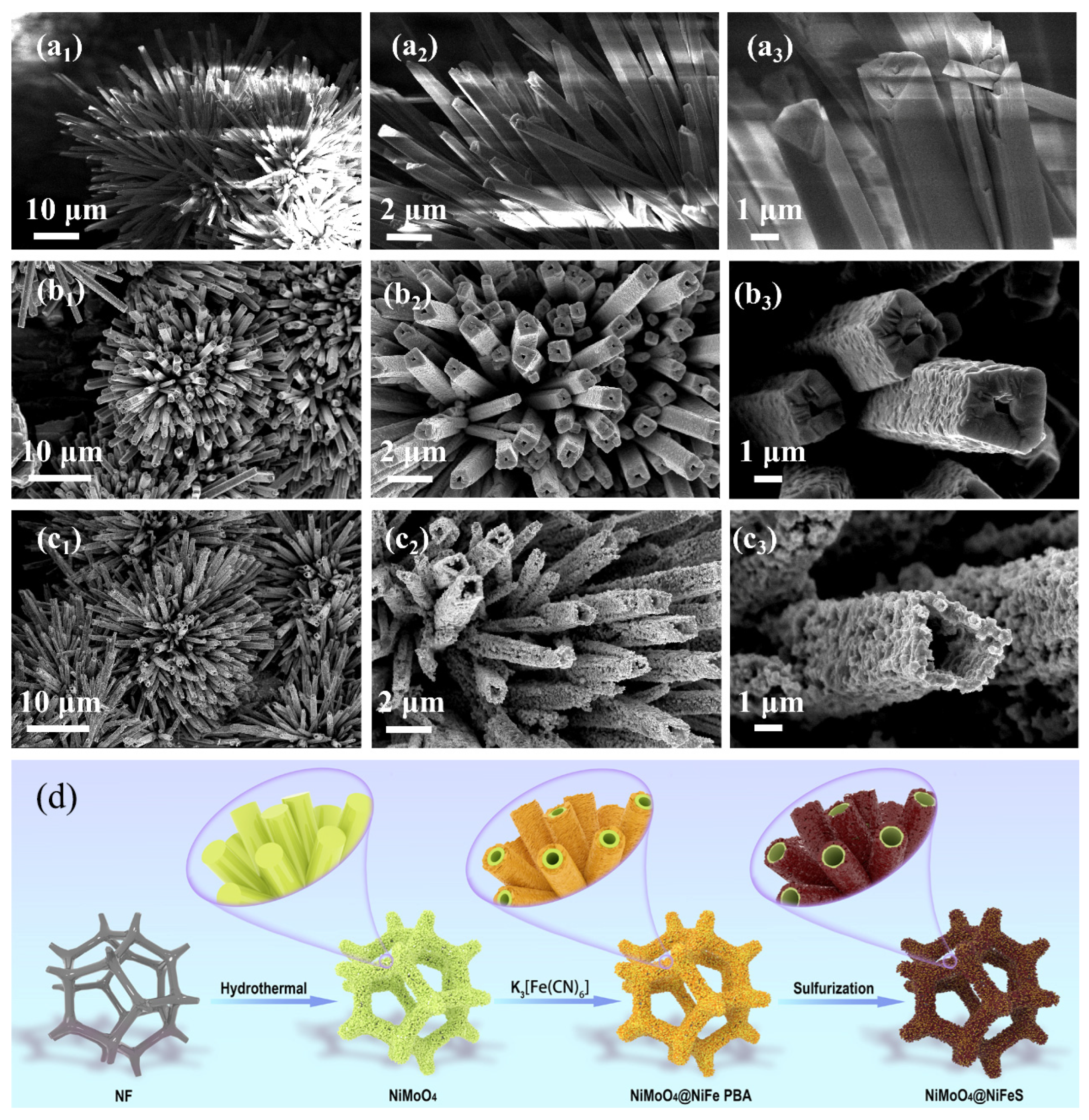
The scanning electron microscopy (SEM) image (Figure 1(a1)) shows that the NiMoO4 electrode exhibits an ordered flower-like array composed of irregular square-shaped microrods. High-resolution SEM images (Figure 1(a2,a3)) reveal that these microrods are solid with smooth and clean surfaces. This ordered flower-like array morphology is preserved in the NiMoO4@NiFe-PBA (Figure 1(b1)) and NiMoO4@NiFeS (Figure 1(c1)) electrodes. However, notable morphological evolution is observed from higher-resolution SEM images. In the NiMoO4@NiFe-PBA electrode, the microrods transform into partially hollow, irregular square-shaped structures featuring radial open pores and rough surfaces (Figure 1(b2,b3)). More strikingly, in the NiMoO4@NiFeS electrode, the microrods develop a markedly hollow and porous architecture with abundant interfaces, a significantly expanded central cavity, and considerably roughened surfaces containing enlarged penetrating pores (Figure 1(c2,c3)). This hierarchical porous structure is distinctly different from previously reported NiMoO4-based core–shell morphologies (microrods, nanorods, or nanoneedles) [9,14,18] and provides a robust physical framework that facilitates electrolyte penetration, active site exposure, charge/mass transfer, bubble release, and favorable surface wettability.
To clarify the cavity evolution during sulfurization, time-dependent SEM characterization was conducted on the samples achieved by sulfurization of NiMoO4@NiFe PBA precursor for 0, 5, 15, 30 and 60 min, respectively. As shown in Figure S1, the tubular size grows larger and larger and the surface becomes rougher and rougher with the extension of sulfurization time, confirming the gradual expansion of the tubular size owing to a Kirkendall-type diffusion process and the transformation from NiFe-PBA to NiFeS. Based on the SEM observations, a possible morphological evolution of the synthesized electrodes is proposed in Figure 1d. Under hydrothermal conditions, typical irregular solid quadrangular prism-shaped NiMoO4 microrods grow in situ and form an ordered flower-like array on a piece of NF. Subsequently, during the etching process in K3[Fe(CN)6] solution, the difference in diffusion rates between K+ and Ni2+ leads to faster dissolution of the inner NiMoO4 and slower deposition of the outer NiFe-PBA nanoflakes. This kinetic mismatch is responsible for the formation of hollow, porous NiMoO4@NiFe-PBA core–shell structures with rough surfaces. The shell thickness can be tuned by adjusting the precursor dosage, water bath temperature and reaction time. Finally, a uniform NiFe PBA shell with a thickness of approximately 75 nm was grown on the surface of NiMoO4 microrods (Figure S3). Upon sulfidation under a nitrogen atmosphere, the reaction between sulfur (S) and NiMoO4@NiFe-PBA generates irregular square NiMoO4@NiFeS microtubes with multilevel structures. As presented in Figure S4, the apparent color evolution of the materials (from yellow to dark orange and then to deep black) further confirms the successful construction of NiMoO4@NiFeS.
For comparison, NiMoO4 was directly sulfidized to obtain S-NiMoO4. It can be seen from Figure S5a that S-NiMoO4 completely maintains the morphology of NiMoO4 without hollow cavities or rough surfaces. S atoms could not penetrate the interior of solid NiMoO4 microrods without the assistance of the diffusion channels created by K3[Fe(CN)6] etching, and the formed compact layers of metal sulfides on the surfaces of NiMoO4 block the inward diffusion of S and the outward migration of metal ions, restricting the reactions of S and metal atoms to an extremely shallow surface depth. On the other hand, NiMoO4@NiFeO was fabricated by direct calcination of NiMoO4@NiFe-PBA without the addition of S powder. As shown in Figure S5b, the ordered flower-like arrays assembled by NiMoO4 microrods collapse in NiMoO4@NiFeO, and the hollow porous irregular square-shaped NiMoO4@NiFe-PBA microrods convert to tabular solid ones, which are constructed by the close stacking of flake-like metal oxides.

2.1.2. Crystalline Structure Characterization

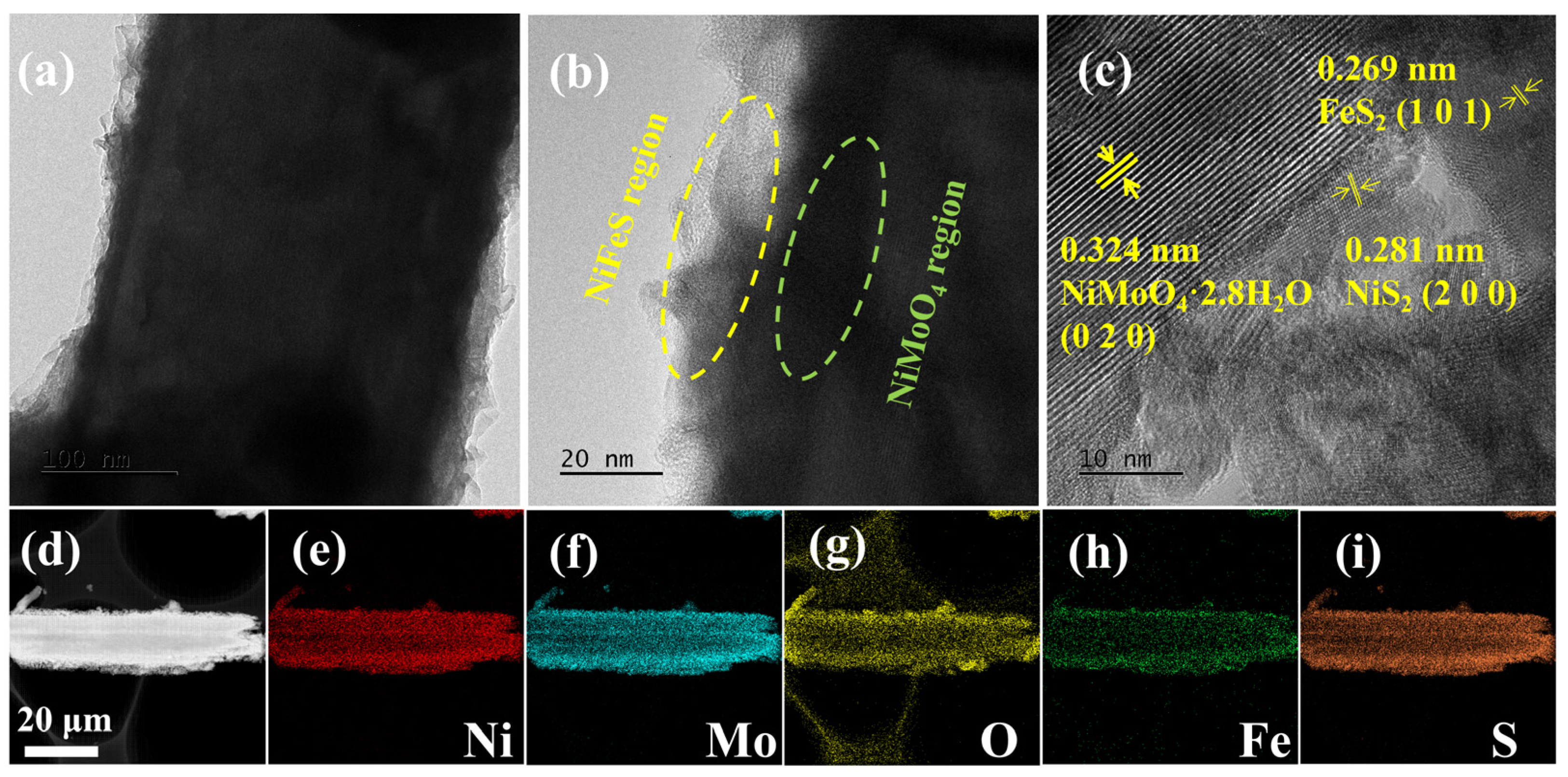
The crystalline structure of the synthesized NiMoO4@NiFeS was initially probed via transmission electron microscopy (TEM) observation. The low-resolution TEM images (Figure 2a,b) evidence the successful fabrication of the integrated NiMoO4@NiFeS irregular square microtubes. The light exterior corresponds to the partially crystalline metal sulfides (MS2, M = Ni or Fe), and the dark edges and uneven interior correspond to the highly crystalline NiMoO4 and the tubular cavity, respectively, confirming the presence of multiple interfaces within the NiMoO4@NiFeS microtubes [19]. In addition, the uneven stacking of the partially crystalline MS2 on the outside surfaces of the highly crystalline NiMoO4 accounts for the significantly rough surface and the extremely strong hydrophilicity of the NiMoO4@NiFeS microtubes. Moreover, in line with the high-resolution TEM (HRTEM) image shown in Figure 2c, the observed lattice fringe with a spacing of 0.324 nm is in good agreement with the d-spacing corresponding to the strongest diffraction peak of NiMoO4·2.8H2O (JCPDS No. 04-017-0338) identified in the following XRD pattern, and the lattice spacings measuring 0.281 and 0.269 nm correspond to the (200) lattice plane of NiS2 (JCPDS No. 11-0099) and the (101) lattice planes of FeS2 (JCPDS No. 74-1051), respectively. The EDX elemental mapping profiles of NiMoO4@NiFeS (Figure 2d–i) confirm the coexistence of Ni, Mo, Fe, O and S elements and the tubular structure of the NiMoO4@NiFeS composite. It should be noted that Ni, Fe and S are uniformly co-distributed in the outside layers, and Ni, Mo and O in the inner layers of the microtube, confirming the formation of an external NiFeS shell and an internal NiMoO4 core. Thus, the flower-like NiMoO4@NiFeS multilevel heterostructure was successfully prepared by the simultaneous self-sacrifice of well-aligned NiMoO4 microrods and phase transformation from PBA to MS2, which facilitates electron transfer across the interfaces of NiMoO4 and sulfides.
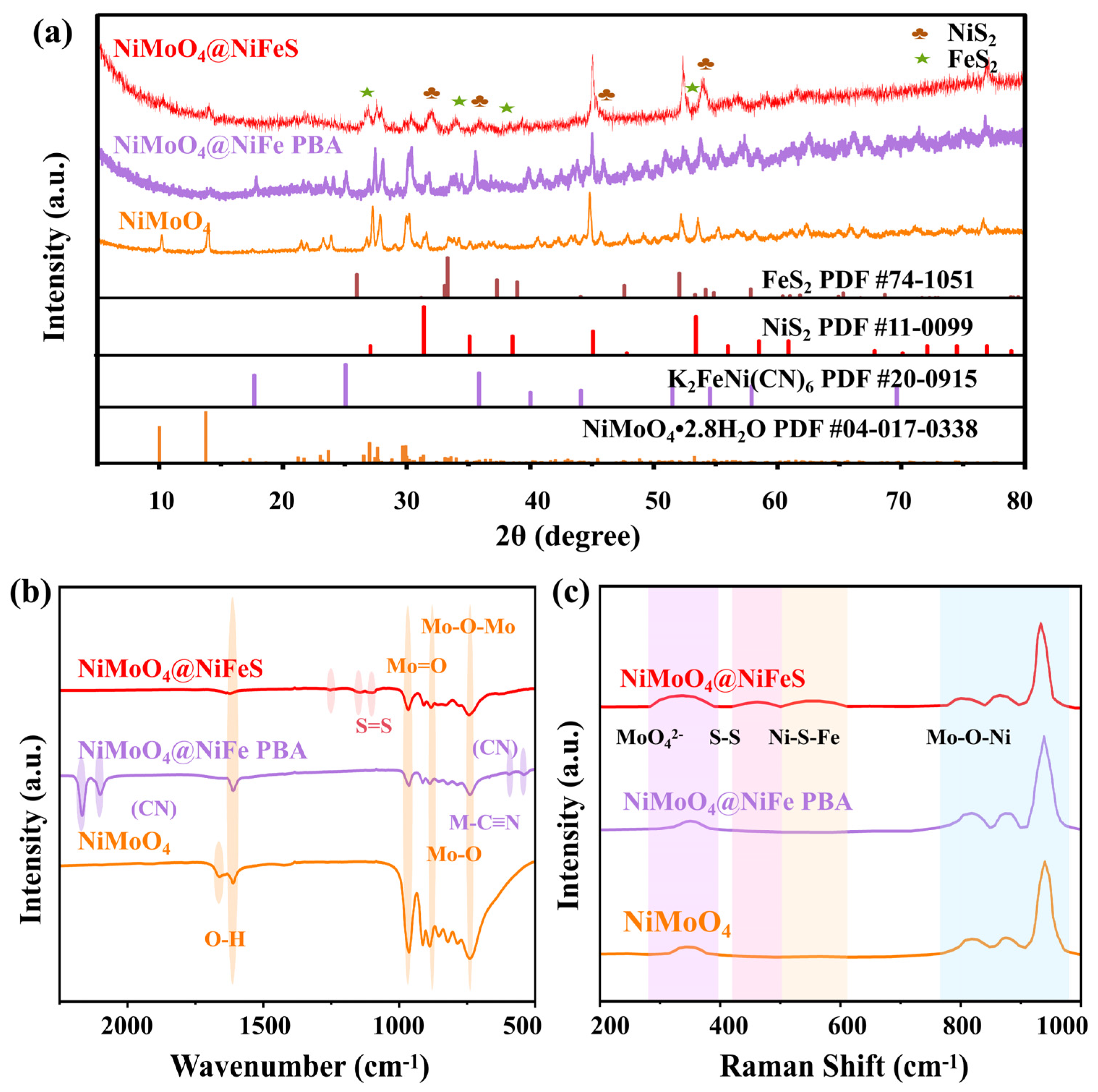
Figure 3a shows the powder X-ray diffraction (XRD) patterns of NiMoO4, NiMoO4@NiFe-PBA and NiMoO4@NiFeS, respectively. The three strong peaks that appeared at 2θ = 44.5°, 51.8° and 76.4° are indexed to the (111), (200) and (220) crystal facets of the metallic NF substrate (JCPDS No. 04-0850), respectively. The XRD pattern of NiMoO4 is in good agreement with previously reported data [20,21,22]. The peaks at 13.5°, 21.1°, 22.8°, 23.0°, 23.5°, 27.2° and 27.5° correspond to the (100), (−1–11), (−111), (112), (102), (210) and (020) crystal planes of NiMoO4·2.8H2O (JCPDS No. 04-017-0338) [23], respectively. In the XRD pattern of NiMoO4@NiFe-PBA, the diffraction peaks observed near 17.6°, 25.0°, 35.8° and 51.4° correspond to the (200), (220), (400) and (440) crystal planes of K2FeNi(CN)6 (JCPDS No. 20-0915), evidencing the partial conversion of NiMoO4 to NiFe-PBA. In the XRD pattern of NiMoO4@NiFeS, the detectable diffraction peaks except those of Ni and NiMoO4 correspond well to the crystal planes of FeS2 and NiS2. The diffraction peaks detected at 25.9°, 33.3°, 37.3°and 52.1° correspond to the (110), (101), (111) and (211) crystal planes of FeS2 (JCPDS No. 74-1051), and those detected at 31.6°, 35.3°, 38.8°, 45.3° and 53.6° correspond to the (200), (210), (211), (220) and (311) crystal planes of NiS2 (JCPDS No. 11-0099) [20], confirming the formation of FeS2 and NiS2 via sulfidation of NiMoO4@NiFe-PBA. The phase composition obtained from Rietveld refinement of the XRD pattern of NiMoO4@NiFeS indicates that the crystallite sizes of NiMoO4, FeS2, and NiS2 are estimated to be approximately 12.8 nm, 21.0 nm, and 14.0 nm, with corresponding phase contents of 38.8%, 4.2%, and 29.7%, respectively (Figure S6). It is noted that the XRD pattern of NiMoO4@NiFeS shows broader and weaker diffraction peaks as well as more unstable baselines with respect to that of NiMoO4, indicating the reduced crystallite size and increased structural disorder of NiMoO4@NiFeS, which aligns with the aforementioned SEM and TEM analytical outcomes. Undoubtedly, the poor crystallization of NiMoO4@NiFeS can lead to more active site exposure and more pathways for electron and ion transport, thereby contributing significantly to the improvement in its OER performance.
Regarding vibrational properties, both Fourier transform infrared (FTIR) and Raman spectroscopy were performed for NiMoO4, NiMoO4@NiFe-PBA and NiMoO4@NiFeS, which were removed from NF by extensive ultrasonication in alcohol and analyzed after drying. In the FTIR spectra shown in Figure 3b, the absorption peaks observed at 742, 887 and 965 cm−1 are attributed to the Mo-O-Mo bending, Mo-O stretching, and Mo=O stretching vibrations of molybdates [24,25,26], respectively. For NiMoO4, the bands detected at 1609 and 1665 cm−1 are assigned to the δ(OH) bending vibrations of surface-adsorbed water and lattice water coordinated with Ni2+/MoO42− [27], respectively. In sharp contrast, the former completely disappears for NiMoO4@NiFe-PBA and NiMoO4@NiFeS, indicative of the transformation of NiMoO4·2.8H2O to NiMoO4. Moreover, those characteristic peaks of MoO42− detected within the 700–1000 cm−1 wavenumber range are significantly weakened for NiMoO4@NiFeS, which may partly stem from the loss of coordinated water molecules. In the FTIR spectrum of NiMoO4@NiFe-PBA, the characteristic peaks at 587, 2095 and 2164 cm−1 correspond to the cyanide (C≡N) moieties derived from K2FeNi(CN)6, and the signal at 537 cm−1 is linked to the M–C≡N (M = Fe or Ni) stretching mode [9]. Significantly, the specific peaks detected at 1098, 1145 and 1253 cm−1 for NiMoO4@NiFeS correspond to the asymmetric/symmetric stretching modes of S atoms [28], verifying the generation of MS2.
To further verify the generation of NiMoO4, NiMoO4@NiFe-PBA and NiMoO4@NiFeS, Raman spectroscopy was employed to analyze their scattering features. As illustrated in Figure 3c, each specimen displays a broad peak near 346 cm−1, linked to the symmetrical stretching mode of MoO42− units in NiMoO4, whereas the Raman signals within 800–1000 cm−1 correspond to Mo-O-Ni linkages [29], verifying the presence of NiMoO4 in these samples. For NiMoO4@NiFeS, the special Raman bands appeared at ca. 460 and 553 cm−1, aligning with the stretching pertaining to S-S linkage within NiS2 [30] and the vibration of the Ni-S-Fe linkage band [31], respectively, offering further support for the formation of FeS2 and NiS2 on the surface of a self-sacrificial template (NiMoO4).

2.1.3. Chemical States and Surface Composition

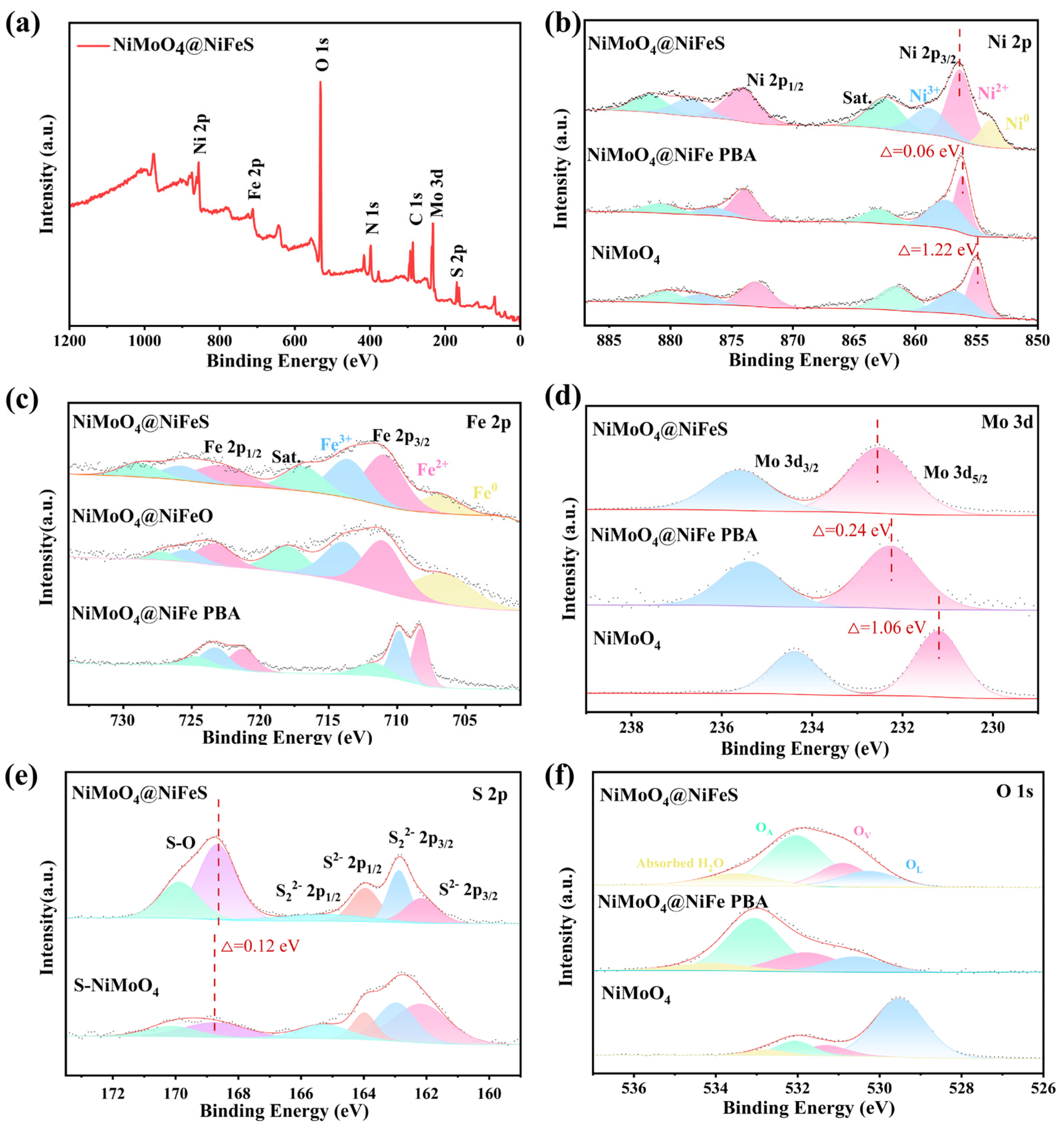
X-ray photoelectron spectroscopy (XPS) was employed to characterize the chemical states and surface composition of NiMoO4@NiFeS. Consistent with the results from above EDX analyses, the survey XPS spectrum reveals the presence of Mo, Ni, Fe, O, C, N and S within NiMoO4@NiFeS (Figure 4a). As indicated in Figure 4b, the deconvoluted Ni 2p profile for NiMoO4@NiFeS reveals the characteristic features of Ni0, Ni2+, Ni3+ and a shakeup satellite [32], respectively. Similar features are also observed for the high-resolution Fe 2p profiles derived from NiMoO4@NiFeO as well as NiMoO4@NiFeS (Figure 4c), from which the typical peaks assignable to Fe0, Fe2+, Fe3+ and a shakeup satellite are deconvoluted, respectively. The appearance of Ni3+ and Fe3+ was clearly ascribed to surface oxidation, whereas the presence of Ni0 and Fe0 could be ascribed to the reduction of Ni2+ and Fe2+ by CN at an elevated temperature, respectively [33]. In contrast, no Ni0 and Fe0 species are detected for NiMoO4 and NiMoO4@NiFe-PBA. Herein, sharp and discrete “two-part” peaks are observed in the XPS spectrum of PBA, correlating strongly with its high crystallinity coupled with a uniform coordination environment [34].
From the core-level Mo 3d (Figure 4d) profile for NiMoO4@NiFeS, the Mo 3d5/2 and Mo 3d3/2 signals appear at 232.5 and 235.6 eV, respectively, alongside a peak separation of 3.1 eV. The same peak separation is also observed for NiMoO4 and NiMoO4@NiFe-PBA, indicating the formation of Mo6+ species. From the high-resolution S 2p scan of NiMoO4@NiFeS (Figure 4e), the S 2p1/2 and S 2p3/2 features emerge at 164.0 and 162.9 eV, assignable to the configurations of apical S2- and bridging S22−, respectively [35]. Additionally, the peaks at 168.7 and 169.9 eV arise from the formation of S-O bonds [36,37,38], also originating from surface oxidation. Within the core-level O 1s profile for NiMoO4@NiFeS (Figure 4f), signals appearing at 530.3, 530.8, 531.7 and 533.4 eV match the binding energies of crystal lattice oxygen (OL), coordination-unsaturated oxygen (OV), surface adsorbed hydroxide oxygen (OA), and physical adsorbed water, respectively. In comparison with NiMoO4 and NiMoO4@NiFe-PBA, NiMoO4@NiFeS displays significantly enhanced OV and OA species and a dramatically reduced OL one, suggesting that OL is effectively activated to OV and OA at the interfaces of NiMoO4 and NiFeS and that the abundant vacancies in NiMoO4/NiFeS are capable of absorbing more OH ions to accelerate the lattice oxygen oxidation–reduction reaction.
On the other hand, it is of interest to note that the Ni 2p, Fe 2p and Mo 3d peaks of NiMoO4@NiFeS are systematically shifted toward higher binding energy relative to those of NiMoO4@NiFe-PBA [9], whereas its S 2p and O 2p peaks are negatively shifted relative to the S 2p of S-NiMoO4 and O 2p of NiMoO4@NiFe-PBA, respectively. These results suggest strong electronic interactions and efficient charge redistribution at the interfaces of NiMoO4 and NiFeS. In addition, the Mo 3d peaks shift systematically to the higher energy end in the sequence of NiMoO4, NiMoO4@NiFe-PBA and NiMoO4@NiFeS, even though Mo remains in a constant valence state. Such a rigid shift in binding energy for a redox-inert element is attributed to the modulation of the Fermi level position in oxides resulting from oxygen vacancy formation [35]. It is expected that both the activation of OL and the charge redistribution at the hetero-structured NiMoO4@NiFeS interfaces can modulate the catalyst’s adsorption energy towards reaction intermediates and redox processes of metal ions, thereby enhancing interfacial transfer of charge/mass and lowering the kinetic barrier of the potential-limiting step.

2.1.4. BET Analysis and Surface Wettability Property

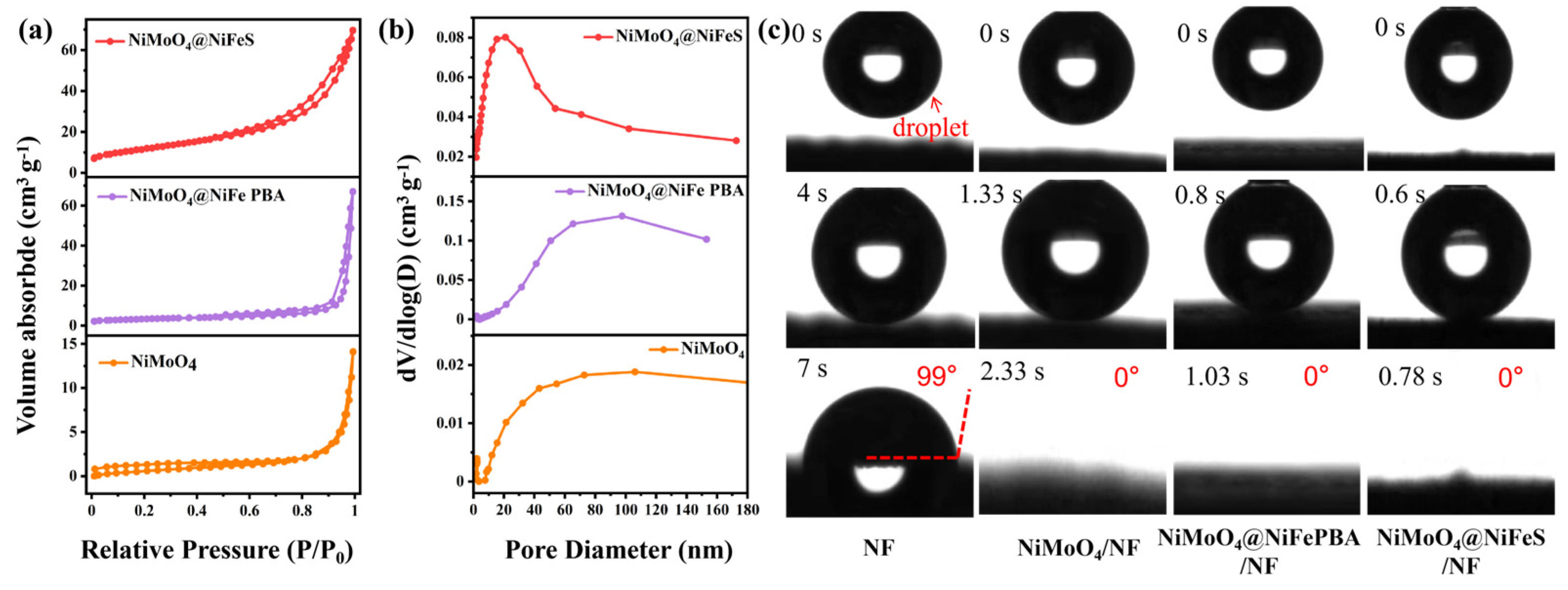
BET analysis provided further evidence of surface area enhancement. In line with the nitrogen adsorption–desorption isotherms shown in Figure 5a, NiMoO4, NiMoO4@NiFe-PBA and NiMoO4@NiFeS demonstrate the characteristic type-IV nitrogen sorption profiles featuring H3-type hysteresis within the P/P0 interval spanning 0.5 to 1.0, suggesting that the stacking of individual particles generates abundant irregular and open mesopores. The BET specific surface areas yielded values of 4.7645, 11.7876 and 43.3591 m2·g−1 for NiMoO4, NiMoO4@NiFe-PBA and NiMoO4@NiFeS, respectively. It should be pointed out here that the BET specific surface area of NiMoO4@NiFeS is twice as much as that of the previously reported NiMoO4/NiFeS [14]. Displayed in Figure 5b are the BJH pore size distribution profiles originating from the adsorption branch of isotherms. Clearly, NiMoO4@NiFeS exhibits the largest cumulative pore volume (0.1078 cm3·g−1 versus 0.0218 and 0.1038 cm3·g−1 for NiMoO4 and NiMoO4@NiFe-PBA, respectively) and the smallest average diameter (9.9436 nm versus 18.3233 and 35.2085 nm for NiMoO4 and NiMoO4@NiFe-PBA, respectively) (Table S1). Moreover, the dominant pores of NiMoO4@NiFeS are distributed in the range of mesopores, and those of NiMoO4 and NiMoO4@NiFe-PBA in the range of macropores. The dominant mesopore, large BET surface area and high porosity of NiMoO4@NiFeS promote the accessibility of electrochemical catalytic centers, charge migration, electrolyte penetration and evolved gas release during the electrocatalysis process, which are expected to benefit the OER activity of NiMoO4@NiFeS.
To estimate the surface wettability property of NiMoO4@NiFeS, contact-angle measurements were performed. As demonstrated in Figure 5c, aqueous droplets disperse instantaneously upon contact with the NiMoO4@NiFeS substrate, and the wetting angle was determined to be 0°. Conversely, the contact angle of NF measured 99°. The contact angle of NiMoO4@NiFeS is markedly lower than that of pristine NF, suggesting that water molecules can more readily wet the surface of this electrode, thereby demonstrating better wettability. The in situ growth of NiMoO4@NiFeS effectively modified the surface properties of NF and created abundant highly active sites. The superhydrophilic surface of NiMoO4@NiFeS plays a significant role for the electrocatalytic reactions that take place at the interfaces of the solid electrode, liquid electrolyte and generated gas bubbles. The wetting time on the surface of NiMoO4@NiFeS (0.78 s) is significantly faster than that of NiMoO4@NiFe-PBA (1.03 s) and NiMoO4 (2.33 s). When the electrode surface is hydrophilic, a uniform and stable water film forms on the surface, and gas bubbles tend to detach preferentially, facilitating rapid wetting and permeation of the electrolyte throughout the electrode matrix via mesoscopic and microscopic pores. This efficiently promotes the transport of electrolyte ions to active sites, ultimately improving the overall electrochemical performance.

2.2. OER Performance in Alkaline Media

2.2.1. LSV Curve Analysis

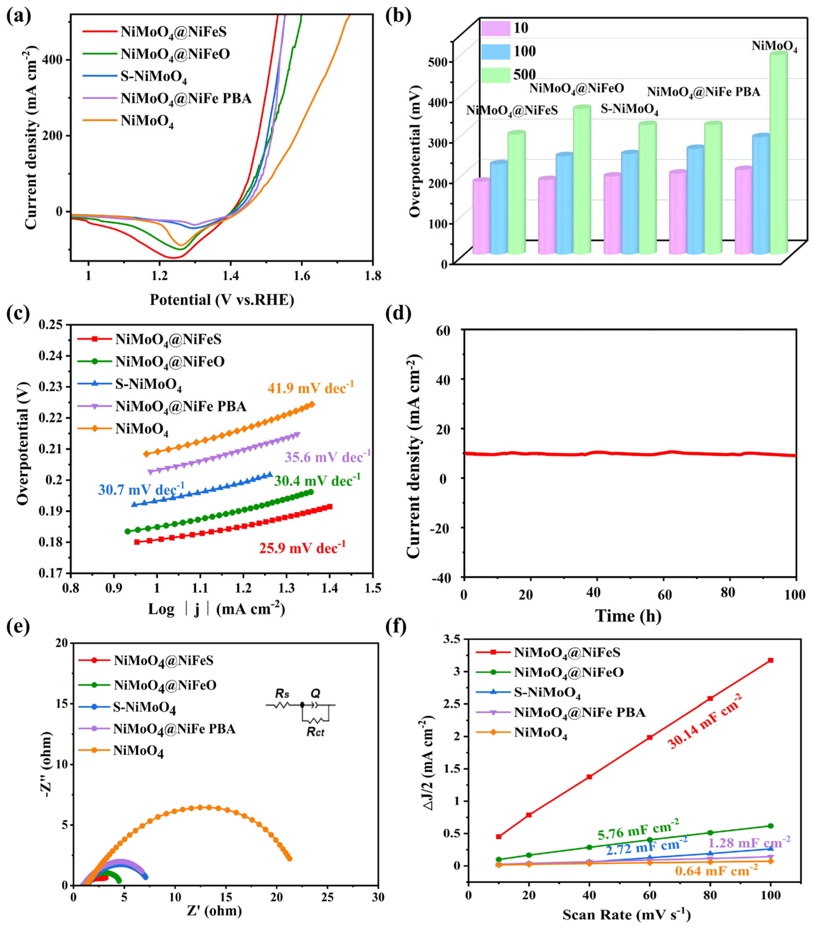
The oxygen evolution reaction (OER) behavior of NiMoO4@NiFeS was systematically evaluated in a conventional three-electrode setup in 1 M KOH solution. Consistent with the LSV profiles displayed in Figure 6a, NiMoO4@NiFeS exhibits superior OER activity featuring minimal overpotentials of 180, 223 and 297 mV at current densities of 10, 100 and 500 mA cm−2, respectively. These values are significantly lower than those of NiMoO4@NiFeO (184, 243 and 360 mV), S-NiMoO4 (193, 248 and 320 mV), NiMoO4@ NiFe-PBA (203, 260 and 320 mV), and NiMoO4 (209, 290 and 493 mV) (Figure 6b). The redox peaks around the overpotential of 0.2 V are assigned to the Ni (II)/Ni (III) redox process, whose integrated areas reflect the total charge transferred from Ni2+ to Ni3+ species. It is noted that the ratio of oxidized Ni decreases dramatically in the order of NiMoO4@NiFeS, NiMoO4@NiFeO, S-NiMoO4, NiMoO4@NiFe-PBA and NiMoO4, which is inversely correlated with their overpotential needed to reach a current density of 10 mA cm−2, indicating that the resultant Ni (III) phase play a role of the catalytic center of these electrocatalysts.

2.2.2. Tafel Curve Analysis

The OER reaction kinetics of the synthesized electrodes were assessed by Tafel slope analyses. As evidenced by Figure 6c, the Tafel slope of NiMoO4@NiFeS is as low as 25.9 mV dec−1, markedly smaller than that of NiMoO4@NiFeO (30.4 mV dec−1), S-NiMoO4 (30.7 mV dec−1), NiMoO4@NiFe-PBA (35.6 mV dec−1), NiMoO4 (41.9 mV dec−1) and the previously reported NiMoO4/NiFeS (36.5 mV dec−1), confirming that the construction of the NiMoO4@NiFeS heterostructure significantly facilitates the OER reaction process. In particular, the superhydrophilic nature of the electrode ensures an intimate, molecular-level interaction with the electrolyte, greatly diminishing the resistance for ion transport and thereby accelerating the reaction kinetics at the solid/liquid interface. As shown in Table 1, the NiMoO4@NiFeS electrode exhibits exceptional OER activity in alkaline media, surpassing many state-of-the-art NiFe-based OER catalysts. Moreover, the activity of NiMoO4@NiFeS at industrial operating temperatures (e.g., 60 or 80 °C) is significantly superior to that at room temperature, indicating its potential for application in actual alkaline water electrolysis processes (Figure S7).

2.2.3. Stability Analysis

Furthermore, both the chronoamperometry (CA) and CV cycling were conducted to assess the durability of NiMoO4@NiFeS within alkaline electrolytes. As shown in Figure 6d, the catalyst can operate stably for over 100 h at a current density of 10 mA·cm−2 without clear current decay. It operates stably at a current density of 500 mA cm−2 for 50 h with only 2% decay (Figure S8). Moreover, the OER LSV curves of NiMoO4@NiFeS demonstrated negligible degradation after continuous 1000 CV cycles (Figure S9). Thus, NiMoO4@NiFeS exhibits admirable long-term stability and durability in alkaline solutions. The ratio of Ni to Fe in NiMoO4@NiFeS, which can be adjusted by the added amount of K3[Fe(CN)6] during the preparation process, also influences the OER stability. As shown in Figure S6, the optimized dosage of 0.012 M adopted in this work achieves a well-balanced structure and stability.

2.2.4. EIS and ECSA Analyses

Initially, the electron-transfer properties of the synthesized materials were probed via electrochemical impedance spectroscopy (EIS). As shown in Figure 6e and Table S2, NiMoO4@NiFeS exhibits the lowest interfacial resistance (Rct) (2.45 Ω), indicating its excellent electrical conductivity and interfacial electron transfer kinetics, which may be attributed to its abundant heterointerfaces and mesoporous architecture serving as pathways for efficient charge transfer. Subsequently, a series of cyclic voltammograms (CVs) were acquired within a non-Faradaic potential window (Figure S10), and then the electrochemical active surface areas (ECSAs) of the obtained electrodes were quantified based on their double-layer capacitance (Cdl) values to probe the density of accessible catalytic sites [53,54]. As depicted in Figure 6f, the recorded Cdl magnitude for NiMoO4@NiFeS is as high as 30.14 mF cm−2, which is 5.2, 11.1, 23.5, and 47.1 times that of NiMoO4@NiFeO (5.76 mF cm−2), S-NiMoO4 (2.72 mF cm−2), NiMoO4@NiFe-PBA (1.28 mF cm−2), and NiMoO4 (0.64 mF cm−2), respectively, suggesting that it has a greater abundance of active sites and superior electrolyte accessibility. Apart from its abundant heterointerfaces and mesoporous architecture, the electrode’s superhydrophilic property also contributes largely to the ECSA by turning its total surface area into accessible three-phase reaction interfaces, thereby greatly increasing the number of accessible active sites. All in all, the expedited charge migration and enlarged electroactive surface area of the NiMoO4@NiFeS heterostructure are collectively accountable for its exceptional OER behavior, rendering NiMoO4@NiFeS a highly promising catalyst for OER.

2.3. Surface Phase Reconstruction/Transition of NiMoO4@FeNiS

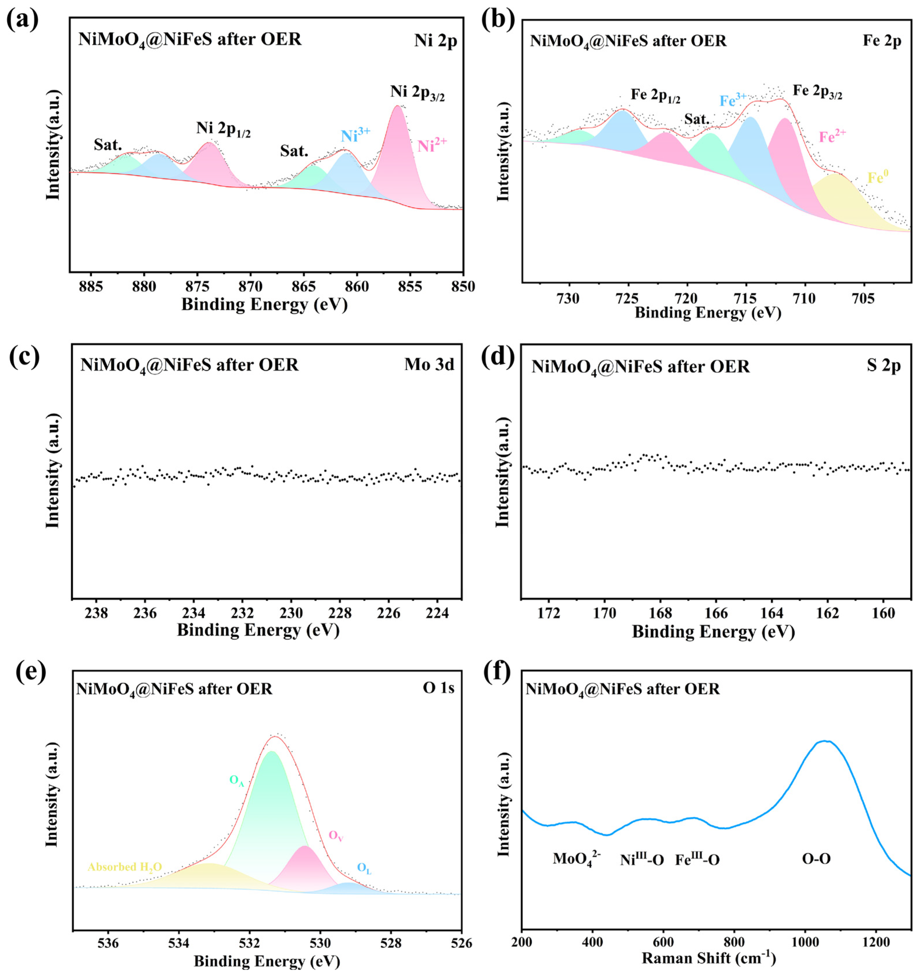
To investigate the evolution of surface chemical states of the catalyst during the electrocatalytic process, XPS characterizations were performed on the NiMoO4@NiFeS electrode after stability testing. It can be seen from the survey XPS spectrum (Figure S11) that the N, Mo and S peaks are no longer detectable, owing to their leaching from the surface of catalyst after the OER test. Within the core-level Ni 2p profile of NiMoO4@NiFeS (Figure 7a), the three deconvoluted spin-orbit split components correspond to the Ni 2p3/2 and Ni 2p1/2 orbitals associated with Ni2+, Ni3+ and corresponding shake-up satellites, respectively. It is noted that the deconvoluted Ni 2p peaks are systematically shifted toward higher binding energy relative to those before stability testing (Figure 4b), and that the peak corresponding to Ni0 disappears, indicating the presence of Ni in a high oxidation state. The enhanced intensity of the Ni3+ peak (Table S3) suggests the formation of NiOOH, whose higher valence state is known to provide favorable adsorption configurations and energetics for OER [55,56]. Similarly, the three deconvoluted spin-orbit doublet peaks observed in Figure 7b represent the Fe 2p3/2 and Fe 2p1/2 states of Fe2+, Fe3+ and corresponding shake-up satellites, respectively, and the marked increase in the Fe3+ signal (Table S3) also indicates the formation of FeOOH during the electrochemical process. Nonetheless, the deconvoluted Fe 2p peaks are systematically shifted toward a lower binding energy relative to those before stability testing (Figure 4c), and the peak corresponding to Fe0 still exists, which could be ascribed to an intermetallic charge transfer effect [57]. With strong electron depletion around Ni sites due to electrons transferring to adjacent oxygen intermediates, the Fe center maintains a relatively reduced state acting as an electron sink. Thus, the Fe center is conductive to maintaining the higher valence state of the Ni one. Within the core-level Mo 3d profile (Figure 7c), the near-surfaced Mo signal disappears, implying their leaching into the electrolyte as soluble MoO42− ions. Similarly, the near-surfaced S signal is not detected within the high-resolution S 2p scan (Figure 7d) either, indicating that the sulfur species on the outermost layer undergo complete oxidative dissolution under OER operation and then leach into the electrolyte as soluble SO42− ions [58]. There is no doubt that the leaching of Mo and S out from NiMoO4@NiFeS not only provides an exceptionally porous architecture with an amplified surface area but also enlarges the number of active sites via exposure of more nickel sites and the generation of surface γ-NiOOH species. Remarkably, the O 1s core-level profile (Figure 7e) reveals a continued elevation in the OA intensity along with a great decrease in that of OL relative to those before OER (Figure 4d), suggesting the occupancy of oxygen vacancies by OH ions from the electrolyte and the formation of more hydroxyl-rich (oxy)hydroxide species associated with active NiFeOOH intermediates [14]. This finding is in good agreement with the increased proportion of high-valence metal species observed in the Ni 2p and Fe 2p spectra, as well as the disappearance of the Mo 3d and S 2p signals, supporting that the OER process occurs following the LOM mechanism. Electron paramagnetic resonance (EPR) measurements (Figure S12) were further performed on NiMoO4@NiFeS before and after OER catalysis. The characteristic paramagnetic signal at g = 2.003 originating from oxygen vacancies is remarkably elevated after OER, demonstrating massive lattice oxygen loss during the phase transformation of sulfides into (oxy)hydroxides and the consequent formation of abundant oxygen vacancies, which is consistent with the XPS analysis.
Aiming at elucidating the structural evolution of NiMoO4@NiFeS during the OER process, Raman scattering characterization was also performed on the NiMoO4@NiFeS electrode after stability testing. From the Raman spectrum shown in Figure 7f, it can be observed that the original sulfide characteristic peaks (S-S, Ni-S-Fe) (Figure 3c) have disappeared, confirming the leaching or oxidative restructuring of sulfur species. Instead, a new set of broad peaks emerges, which offers compelling spectroscopic evidence for the formation of γ-Fe/NiOOH species. Among them, the broad peak near 553 cm−1 might originate from the NiIII-O stretching vibration of γ-NiOOH, and the one at 690 cm−1 from the FeIII-O stretching vibration of γ-FeOOH [43,59]. Moreover, a broad and strong “active oxygen” O-O stretching mode appears dominantly around 1079 cm−1. In contrast, neither FeIII-O stretching vibration nor an “active oxygen” O-O stretching mode was detected for the in situ Raman spectra of the previously reported NiMoO4/NiFeS [14]. Therefore, Raman analysis confirms the presence of α-NiMoO4, γ-NiOOH and γ-FeOOH in NiMoO4@NiFeS after stability testing. For the LOM pathway, the formed O-O bonds are responsible for the generation of oxygen vacancies, indirectly reflecting that lattice oxygen is involved in the OER process [60,61]. It should be pointed out that the NiIII-O, FeIII-O and O-O moieties detected herein are neither protonated nor bonded to a neighboring OH group, indicating that the immediate participation of lattice oxygen leads to a reduced energy barrier for activating the (oxy)hydroxide surface. Furthermore, the significant broadening of these peaks indicates that the newly generated active phase possesses lower crystallinity or amorphous structure, which is a typical feature of highly efficient electrocatalysts.
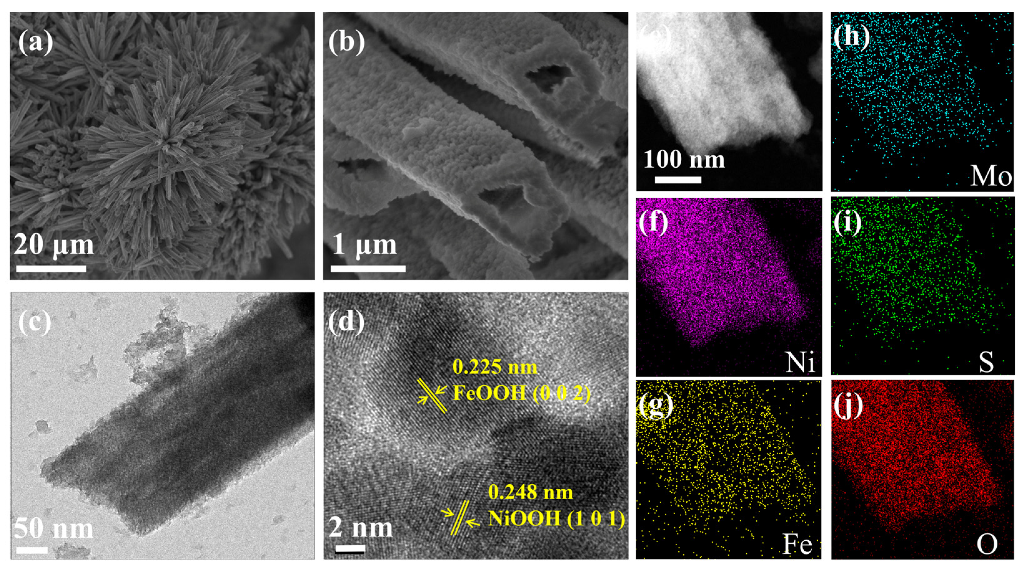
In order to deeply investigate the structural stability and active phase evolution, the NiMoO4@NiFeS electrode after stability testing was investigated by SEM and TEM observation. Moreover, the SEM images shown thereafter (Figure 8a,b) reveal that the NiMoO4@NiFeS electrode after stability testing perfectly maintains the same multileveled flower-like morphology assembled by microtubes as before stability testing (Figure 1(c1–c3)), and no clear aggregation or structural collapse is observed even after undergoing severe anodic oxidation and gas bubble evolution, indicating that the as-prepared self-supported electrode also possesses outstanding mechanical structural stability and excellent corrosion resistance. The low-resolution TEM image (Figure 8c) reveals an uneven and amorphous coating layer on the solid body, evidencing the multiple interfaces between the poorly crystalline MOOH (M = Ni or Fe) and the highly crystalline NiMoO4. Moreover, from the HRTEM image (Figure 8d), two distinct lattice fringes are clearly distinguished, to elucidate the microstructure of the coating layer. The one with 0.248 nm spacing corresponds to the (101) crystalline plane of NiOOH [62], and that with 0.225 nm spacing to the (002) crystalline plane of FeOOH [63], confirming the in situ formation of FeOOH and NiOOH active species during the OER process. Meanwhile, the EDS mapping revealed the uniform dispersion of Mo, Ni, Fe, S and O elements (Figure 8e–j). In comparison with those before stability testing (Figure 2d–i), the signal intensities of Mo and S reduce to some extent, confirming their leaching as soluble species under an alkaline and oxidative environment. In contrast, no clear change is observed for the signal intensities of Ni, Fe and O, owing to the generation of a bimetallic Fe-Ni (oxy)hydroxide via in situ reconstruction of NiMoO4@NiFeS.

2.4. DFT Calculations

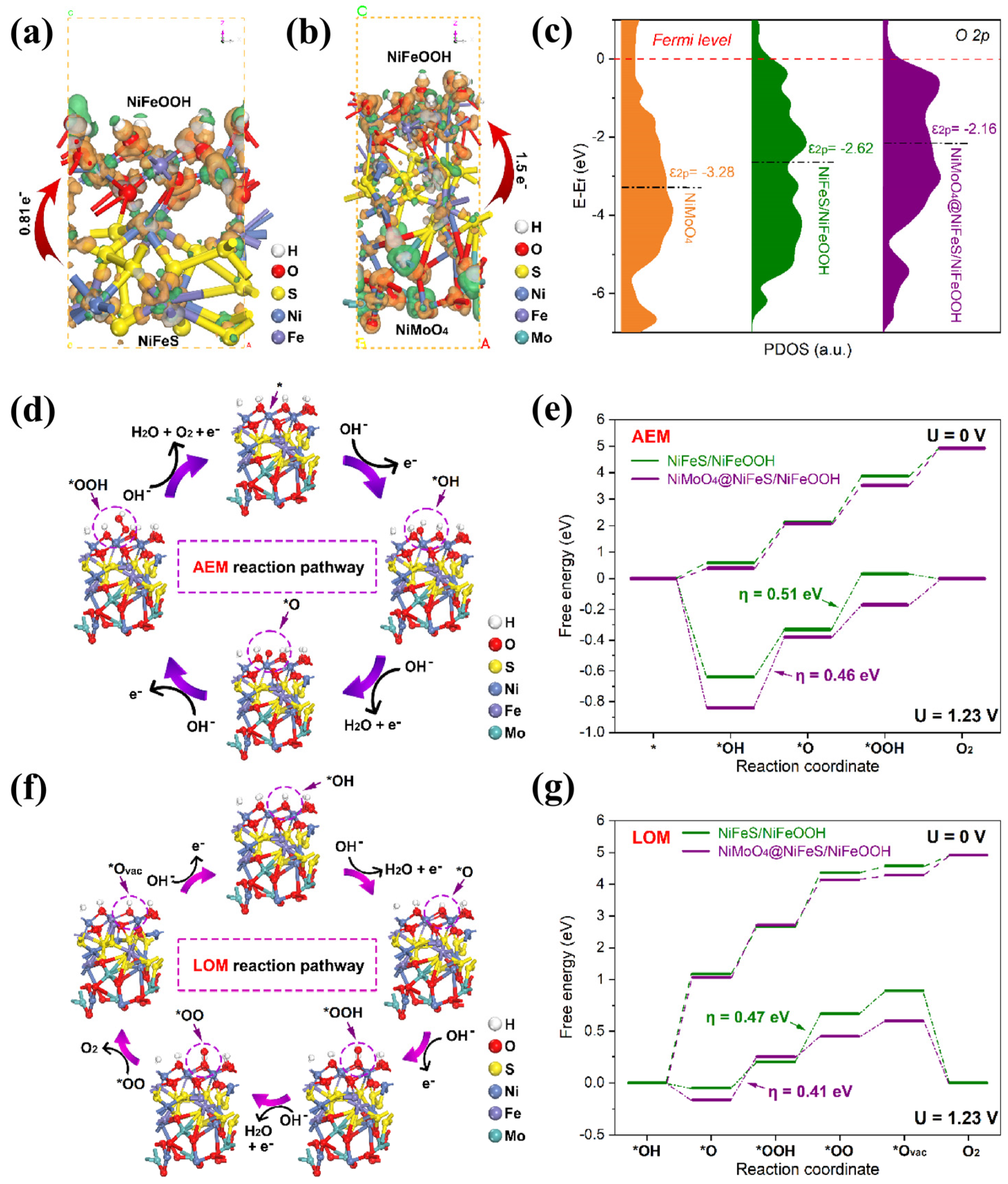
Density functional theory (DFT) calculations were performed to elucidate the origin of the intrinsic catalytic activity for the oxygen evolution reaction (OER). Both the electronic structures of the catalysts and the adsorption energetics of key intermediates were systematically investigated. As evidenced above, the core–shell–shell structured NiMoO4@NiFeS/NiFeOOH was formed via the surface phase reconstruction of NiMoO4@NiFeS during OER. Accordingly, theoretical models of NiMoO4, NiFeS, NiFeS/NiFeOOH, and NiMoO4@NiFeS/NiFeOOH were constructed for comparative analysis (Figure S13). Charge density difference analysis reveals an electron transfer of approximately 0.81 e from NiFeS to the surface-reconstructed NiFeOOH active layer in the NiFeS/NiFeOOH heterojunction (Figure 9a and Figure S14a). In contrast, the NiMoO4@NiFeS/NiFeOOH composite material exhibits a substantially enhanced electron transfer of about 1.5 e from the inner NiMoO4@NiFeS heterojunction towards the outer NiFeOOH layer (Figure 9b and Figure S14b), showing the distribution of enriched electrons and holes on NiMoO4@NiFeS/NiFeOOH. These results indicate that the formation of heterojunctions and interfacial charge rearrangement collectively facilitate charge transport and modulate the electronic structure of NiFeOOH.
The effect of electronic structure modulation on the O 2p band center (ε2p) of NiMoO4@NiFeS/NiFeOOH was analyzed by projected density of states (PDOS) (Figure 9c). Relative to pristine NiMoO4, the ε2p of NiFeS/NiFeOOH and NiMoO4@NiFeS/NiFeOOH shift upward to −2.62 eV and −2.16 eV, respectively. This upshift results in deeper penetration of the Fermi level into the O 2p band, which facilitates electrons flowing away from oxygen sites under an applied anodic potential, thereby promoting lattice oxygen release [59,64,65]. Consequently, the higher ε2p positions in NiFeS/NiFeOOH and NiMoO4@NiFeS/NiFeOOH facilitate oxygen vacancy formation more readily than in pristine NiMoO4, favoring the lattice oxygen oxidation mechanism (LOM) pathway for OER. The traditional adsorbate evolution mechanism (AEM) pathway [14,66] on Ni sites is illustrated in Figure 9d and Figure S15. Initially, OH− is adsorbed at the active site (*), generating a *OH radical and releasing one electron. This *OH intermediate subsequently undergoes proton-coupled electron transfer to form *O, accompanied by the release of a water molecule and an additional electron. Nucleophilic attack of OH on *O then yields the *OOH intermediate, along with one electron. Finally, *OOH reacts with OH to produce O2, a water molecule, an electron, and a regenerated active site. The corresponding free energy diagrams reveal that the formation of *OOH from *O is the rate-determining step (RDS) for pristine NiMoO4, NiFeS, and NiFeS/NiFeOOH, with overpotentials (ηs) of 0.62, 0.55 and 0.51 eV, respectively (Figure 9e and Figure S16).
In contrast, for the Ni sites in the reconstructed NiMoO4@NiFeS/NiFeOOH catalyst, the RDS shifts to the formation of *O from *OH, and the corresponding η decreases to 0.46 eV (Figure 9e). On the other hand, the lattice oxygen-mediated LOM pathway for NiFeS/NiFeOOH and NiMoO4@NiFeS/NiFeOOH was further analyzed (Figure 9f and Figure S17). This pathway can be divided into five steps: (i) deprotonation of the electrocatalyst to generate exposed lattice oxygen; (ii) nucleophilic attack of OH on lattice oxygen; (iii) O-O coupling; (iv) release of O2, leaving behind oxygen vacancies (*Ovac); and (v) replenishment of oxygen vacancies by OH [67,68]. As shown in Figure 9g, the energy barriers for the RDS of the LOM pathway for NiFeS/NiFeOOH and NiMoO4@NiFeS/NiFeOOH are 0.47 and 0.41 eV, respectively. These values are lower than those for the corresponding AEM pathways (0.51 eV and 0.46 eV). The lower energy barriers for the LOM pathway can be attributed to the direct O-O coupling from lattice oxygen, which avoids the formation of high-energy *OOH intermediates required in the AEM pathway. This computational finding is consistent with the experimental results (Figure S18), where the OER activity shows a strong pH dependence, further confirming that the OER preferentially proceeds via the LOM route on these catalysts. For NiFeS/NiFeOOH, the RDS of the LOM pathway is the O-O coupling step. Notably, after the introduction of NiMoO4, the substantial interfacial electron injection (1.5 e) from the inner core–shell structured NiMoO4@NiFeS to the NiFeOOH layer significantly elevates the O 2p band center (ε2p) and then promotes the formation of oxygen vacancies and the release of lattice oxygen, which effectively reduces the energy barrier of this step and shifts the RDS to the *OOH formation step, revealing a deep activation effect of NiMoO4 on the LOM pathway.

3. Materials and Methods

3.1. Materials

Nickel nitrate hexahydrate (Ni(NO3)2·6H2O, Tianjin Guangfu Technology Development Co., Ltd., Tianjin, China), ammonium molybdate tetrahydrate ((NH4)6Mo7O24·4H2O, Shanghai Macklin Biochemical Technology Co., Ltd., Shanghai, China), potassium ferricyanide (K3[Fe(CN)6], Tianjin Bodi Chemical Co., Ltd., Tianjin, China), sulfur powder (Tianjin Kemiou Chemical Reagent Co., Ltd., Tianjin, China), potassium hydroxide (KOH, Sinopharm Chemical Reagent Co., Ltd., Shanghai, China), and hydrochloric acid (HCl, ~36.0–38.0% aqueous solution, Tianjin Kemiou Chemical Reagent Co., Ltd., Tianjin, China) were of analytical grade and applied as received. Commercial nickel foam (NF, Wuzhou Sanhe New Materials Technology Co., Ltd., Wuzhou, China) and deionized water (18.2 MΩ.cm, Shanghai Hitech Instruments Co., Ltd., Shanghai, China) were utilized throughout the experiments.

3.2. Synthesis of NiMoO4@NiFeS

Preparation of NiMoO4: Typically, NiMoO4 microrod arrays were grown in situ on NF via a hydrothermal method. First, a piece of NF (2 × 2 cm) was sequentially ultrasonicated in acetone and 0.5 M HCl for 10 min each, followed by thorough rinsing with deionized water and ethanol. Subsequently, 1.16 g of Ni(NO3)2·6H2O and 0.7 g of (NH4)6Mo7O24·4H2O were ultrasonically dissolved in 50 mL of deionized water. The resulting green solution together with the cleaned NF was then transferred into a 100 mL Teflon-lined autoclave and kept at 150 °C for 6 h. After the autoclave had cooled to room temperature, the as-prepared NiMoO4/NF electrode was collected and alternately washed with ethanol and deionized water. Finally, after drying at 60 °C for 12 h, an electrode with a yellow surface (denoted as NiMoO4) was obtained.
Preparation of NiMoO4@NiFe-based Prussian blue analogues (NiMoO4@NiFe-PBA): In this step, 0.2 g of K3[Fe(CN)6] was completely dissolved in 50 mL of deionized water. Then, the as-synthesized NiMoO4 was immersed in this solution. The reaction was carried out in a water bath at 90 °C for 30 min. After that, the product was carefully collected and rinsed three times alternately with deionized water and ethanol. Finally, it was dried at 60 °C for 12 h, yielding the dark orange NiMoO4@NiFe-PBA electrode.
Preparation of NiMoO4@NiFeS: Typically, the as-prepared NiMoO4@NiFe-PBA electrode and 100 mg of sulfur powder were placed in two separate ceramic boats. These boats were then positioned in a tube furnace with a distance of 5 cm between them, where the sulfur powder was placed upstream and the NiMoO4@NiFe-PBA electrodes downstream. Subsequently, the tube furnace was heated to 350 °C at a ramp rate of 5 °C min−1 and maintained at this temperature for 1 h under a flowing N2 atmosphere (60 mL min−1). After the furnace had cooled to room temperature, the deep black NiMoO4@NiFeS electrode was obtained. For comparison, NiMoO4@NiFeO and S-NiMoO4 were also prepared following the same procedure, except that no sulfur powder was added for the former and NiMoO4 was used instead of NiMoO4@NiFe-PBA for the latter, respectively.

3.3. Characterizations

The morphology of the synthesized electrodes was observed using scanning electron microscopy (SEM, Hitachi S-4800, Hitachi, Tokyo, Japan), and their crystalline structure and lattice fringes were investigated via transmission electron microscopy (TEM, JEM-2010, JEOL, Tokyo, Japan) operating at an accelerating voltage of 200 kV. Elemental mapping was conducted on an energy-dispersive X-ray (EDX) spectrometerscope attached to the TEM. Powder X-ray diffraction (XRD, Bruker D8 Advanced diffractometer, Bruker AXS GmbH, Karlsruhe, Germany) equipped with Cu Kα radiation (λ = 1.5418 Å) was employed to analyze the crystal phases. The chemical composition and oxidation states were examined by X-ray photoelectron spectroscopy (XPS, AXIS ULTRA DLD, Kratos Analytical, Manchester, UK), and the binding energies were calibrated with reference to the C 1s peak at 284.8 eV. Fourier transform infrared (FT-IR) spectra were recorded on a PerkinElmer 100FT-IR (Waltham, MA, USA) spectrometer using KBr pellets for background correction. Raman scattering spectra were collected using a Jobin Yvon (Palaiseau, France) HR 800 micro-Raman spectrometer with 458 nm excitation. Nitrogen adsorption–desorption isotherms were measured using a volumetric adsorption analyzer (BET, Micromeritics TRISTAR II 3020, Micromeritics Instrument Corp, Norcross, GA, USA), and the specific surface area and pore size distribution were calculated. The water contact angle on the material surface was measured using a contact angle tester (Theta Flex, Biolin Scientific, Gothenburg, Sweden) to evaluate its hydrophilic/hydrophobic properties and surface wetting characteristics.

3.4. Electrochemical Measurements

Electrochemical measurements were performed on a Bio-Logic SP-300 workstation (Bio-Logic, Seyssinet-Pariset, France) using a conventional three-electrode configuration in 1 M KOH. The working electrode was the as-prepared NiMoO4@NiFeS electrode (along with the control electrode) with a geometric area of 1.0 cm2. An Hg/HgO (1 M KOH) electrode and a Pt plate (1 cm2) served as the reference and counter electrodes, respectively. All measured potentials were converted to the reversible hydrogen electrode (RHE) scale using the following equation:
ERHE = EHg/HgO + 0.098 + 0.059 × pH,
Linear sweep voltammetry (LSV) curves were recorded at a scan rate of 1 mV·s−1 with iR-correction. The Tafel slope is obtained from the Tafel equation as follows: η = b × log (j/j0), where η is the overpotential, b is the Tafel slope, j is the current density, and j0 is the exchange current density, respectively. The electrochemical double-layered capacitance (Cdl) was determined by the CV method with a N2− saturated 1.0 M KOH aqueous solution and in a non-Faradaic region at different scan rates (10, 20, 40, 60, 80 and 100 mV s−1). Electrochemical impedance spectroscopy (EIS) measurements were conducted over a frequency range from 100 kHz to 0.01 Hz with amplitude of 10 mV.

3.5. Theoretical Calculations

DFT calculations were performed by using the CASTEP code. The Perdew–Burke–Ernzerhof (PBE) exchange-correlation functional was used with the generalized gradient approximation (GGA) and a plane-wave cutoff energy of 500 eV. The ion–electron interaction was modelled by the frozen core projector augmented wave (PAW) pseudopotentials. A 3 × 4 × 2 k-point mesh was used for Brillouin zone sampling. Spin-polarized calculations were enabled, and DFT-D (TS scheme) dispersion correction was applied to account for van der Waals interactions at the heterointerface. DFT with the Hubbard-U approach (DFT+U) was employed with effective U values of 4.0, 4.3, and 4.0 eV for Ni, Fe, and Mo, respectively. The models of NiMoO4, NiFeS, NiFeS/NiFeOOH, and NiMoO4@NiFeS/NiFeOOH were constructed with optimized total thicknesses of ~4.2 Å, ~4.4 Å, ~8.1 Å, and ~12.6 Å, respectively. A vacuum layer of thickness 15 Å was employed to isolate periodic effects. All structural models were thoroughly optimized with convergence criteria of 1.0 × 10⁻⁵ eV atom−1 for total energy and 0.02 eV Å−1 for maximum force. Detailed computational parameters are provided in the Supporting Information.

4. Conclusions

In summary, a self-supporting electrode composed of the arrays of mesoporous NiMoO4@NiFeS microtubes was fabricated by gas-phase sulfidation of NiMoO4@NiFe-PBA microrods. The mesoporous structure and superhydrophilic nature of these microtube arrays contribute an enlarged electrochemical active surface area for easy electrolyte penetration and rapid bubble release. The interfacial electronic coupling between NiMoO4 and NiFeS induces in situ surface reconstruction and the generation of a bimetallic Fe-Ni (oxy)hydroxide phase (γ-Ni/FeOOH) with an increased number of oxygen vacancies and accessible nickel sites under anodic potential. Identified as virtual active species, the thermodynamically stable high-valence metal (oxy)hydroxides are responsible for the marvelous OER performance of the heterogeneous electrocatalyst. A series of electrochemical measurements evidenced that the self-supporting NiMoO4@NiFeS electrode outperformed most of the state-of-the-art non-precious metal-based OER electrocatalysts. DFT calculations further reveal the charge redistribution at the hierarchical interfaces of the core–shell–shell structured NiMoO4@NiFeS/NiFeOOH after the OER test, which leads to the O 2p band center being elevated significantly towards the Fermi level and thereby promotes the formation of oxygen vacancies and the release of lattice oxygen. Theoretical calculations also support the contribution of a self-sacrificing template (NiMoO4) to the optimization of the energy barrier of the RDS step. Therefore, both experimental and theoretic results support that the LOM pathway takes precedence over the traditional AEM one. This work presents a rational design strategy that integrates heterojunction engineering with microstructural tailoring to develop cost-effective and durable OER electrocatalysts.

Supplementary Materials

The following supporting information can be downloaded at https://www.mdpi.com/article/10.3390/catal16070621/s1, Figure S1. Scanning electron microscopy (SEM) images of the NiMoO4@NiFeS samples achieved by sulfurization of NiMoO4@NiFe PBA precursor for (a) 0, (b) 5, (c) 15, (d) 30 and (e) 60 min, respectively; Figure S2. (a–c) Low-magnification SEM images of (a) NiMoO4, (b) NiMoO4@NiFe-PBA and (c) NiMoO4@NiFeS; (d–i) TEM images of NiMoO4@NiFeS observed from one (a–c) and the other (d–f) regions; Figure S3. (a) Low-resolution and (b) high-resolution TEM images and (c–j) EDX elemental mapping images of the NiMoO4@NiFe PBA microtube; Figure S4: Optical images of the electrodes at different preparation stages: (a) NiMoO4, (b) NiMoO4@NiFe PBA, and (c) NiMoO4@NiFeS; Figure S5: SEM images of (a) S-NiMoO4 and (b) NiMoO4@NiFeO; Figure S6. Rietveld refinement profile for the powder XRD data of NiMoO4@NiFeS; Figure S7: (a) LSV polarization curves, (b) Tafel plots of NiMoO4@NiFeS measured in 1 M KOH at temperatures of 25, 60 and 80 °C, respectively; Figure S8. Chronoamperometric stability test of the NiMoO4@NiFeS/NF at a current density of 500 mA cm−2 in 1.0 M KOH; Figure S9. LSV curves of NiMoO4@NiFeS electrodes prepared with different concentrations of K3[Fe(CN)6] (0.006 M, 0.012 M, and 0.024 M) before and after 1000 cyclic voltammetry cycles; Figure S10: CV curves of (a) NiMoO4@NiFeS, (b) NiMoO4@NiFeO, (c) S-NiMoO4, (d) NiMoO4@NiFe PBA, and (e) NiMoO4 at various scan rates; Figure S11: The survey XPS spectrum of NiMoO4@NiFeS after OER test; Figure S12. EPR spectra of NiMoO4@NiFeS before and after OER performance; Figure S13: The optimized side view structural models for NiMoO4 (a), NiFeS (b), NiFeS/NiFeOOH (c) and NiMoO4@NiFeS/NiFeOOH (d). The white, red, yellow, royal blue, purple and turquoise balls represent H, O, S, Ni, Fe and Mo atoms, respectively; Figure S14: Bader charge analyses for NiFeS/NiFeOOH (a) and NiMoO4@NiFeS/NiFeOOH (b). The white, red, yellow, royal blue, purple and turquoise balls represent H, O, S, Ni, Fe and Mo atoms, respectively; Figure S15: Schematic illustration of the AEM reaction pathway on NiMoO4 (a), NiFeS (b) and NiFeS/NiFeOOH (c); Figure S16: Free-energy diagrams for the AEM reaction pathway on Ni sites of NiMoO4 (a) and NiFeS (b); Figure S17: Schematic illustration of the LOM reaction pathway on NiFeS/NiFeOOH; Figure S18: The OER current densities of NiMoO4@NiFeS at different pH values. Typically, a ρ value approaching 1 suggests a preference for LOM, indicating that NiMoO4@NiFeS predominantly follows the LOM instead of the AEM, while lattice oxygen plays a direct role in the reaction; Table S1: Surface area, pore volume, and pore size of NiMoO4, NiMoO4@NiFe PBA, and NiMoO4@NiFeS; Table S2: Parameters obtained by fitting the Nyquist plots of NiMoO4@NiFeS, NiMoO4@NiFeO, S-NiMoO4, NiMoO4@NiFe PBA and NiMoO4 using the equivalent circuit in Figure 6e. The impedance of Q is defined as ZQ = 1/[T(jω)n], where T is the CPE constant (CPE-T) with units of F⋅s(n − 1) and n is the CPE exponent (CPE-P, 0 ≤ n ≤ 1); Table S3: XPS area ratios of Ni 2p and Fe 2p for NiMoO4@NiFeS before and after OER test.

Author Contributions

X.H.: Investigation, Validation, Writing—Original Draft. H.W.: Formal Analysis, Writing—Original Draft. J.L.: Data Curation. X.J.: Visualization. Y.Z.: Data Curation. Y.L.: Conceptualization, Resources, Supervision, Writing—Review and Editing. All authors have read and agreed to the published version of the manuscript.

Funding

This work was financially supported by the National Natural Science Foundation of China (52102097).

Data Availability Statement

The data presented in this study are available on request from the corresponding author.

Acknowledgments

The authors thank all the researchers who provided assistance.

Conflicts of Interest

The authors declare no conflicts of interest.

References

  1. Chu, S.; Majumdar, A. Opportunities and Challenges for a Sustainable Energy Future. Nature 2012, 488, 294–303. [Google Scholar] [CrossRef] [PubMed]
  2. Song, J.J.; Wei, C.; Huang, Z.F.; Liu, C.T.; Zeng, L.; Wang, X.; Xu, Z.J. A Review on Fundamentals for Designing Oxygen Evolution Electrocatalysts. Chem. Soc. Rev. 2020, 49, 2196–2214. [Google Scholar] [CrossRef] [PubMed]
  3. Chen, Z.W.; Higgins, D.; Yu, A.P.; Zhang, L.; Zhang, J.J. A review on Non-precious Metal Electrocatalysts for PEM Fuel Cells. Energy Environ. Sci. 2011, 4, 3167–3192. [Google Scholar] [CrossRef]
  4. Yu, J.M.; Le, T.A.; Tran, N.Q.; Lee, H.Y. Earth-Abundant Transition-Metal-Based Bifunctional Electrocatalysts for Overall Water Splitting in Alkaline Media. Chem. Eur. J. 2020, 26, 6423–6436. [Google Scholar] [CrossRef] [PubMed]
  5. Wang, J.; Xu, F.; Jin, H.Y.; Chen, Y.Q.; Wang, Y. Non-Noble Metal-Based Carbon Composites in Hydrogen Evolution Reaction: Fundamentals to Applications. Adv. Mater. 2017, 29, 1605838. [Google Scholar] [CrossRef] [PubMed]
  6. Zhang, Q.; Zhang, W.; Zhu, J.W.; Zhou, X.Y.; Xu, G.R.; Chen, D.H.; Wu, Z.X.; Wang, L. Tuning d-p Orbital Hybridization of NiMoO4@Mo15Se19/NiSe2 Core-Shell Nanomaterials via Asymmetric Coordination Interaction Enables the Water Oxidation Process. Adv. Energy Mater. 2024, 14, 2304546. [Google Scholar] [CrossRef]
  7. Zhu, J.L.; Qian, J.M.; Peng, X.B.; Xia, B.R.; Gao, D.Q. Etching-Induced Surface Reconstruction of NiMoO4 for Oxygen Evolution Reaction. Nano-Micro Lett. 2023, 15, 30. [Google Scholar] [CrossRef] [PubMed]
  8. Zhang, Y.J.; Yao, R.; Wu, Y.; Zhao, Q.; Li, J.P.; Liu, G. In Situ Rapid and Deep Self-Reconstruction of Fe-Doped Hydrate NiMoO4 for Stable Water Oxidation at High Current Densities. Chem. Eng. J. 2023, 461, 142081. [Google Scholar] [CrossRef]
  9. Guo, D.X.; Zhao, Z.; Zong, M.Y.; Fan, C.Z.; Zheng, W.J.; Wang, D.H. Engineered Superhydrophilic/Superaerophobic Array Electrode Composed of NiMoO4@NiFeP for High-Performance Overall Water/Seawater Splitting. ACS Sustain. Chem. Eng. 2023, 11, 8362–8373. [Google Scholar] [CrossRef]
  10. Zhao, F.Z.; Mao, X.Y.; Zheng, X.; Liu, H.C.; Zhu, L.Q.; Li, W.P.; Wang, Z.; Chen, H.N. Roles of the Self-Reconstruction Layer in the Catalytic Stability of a NiFeP Catalyst during the Oxygen Evolution Reaction. J. Mater. Chem. A 2023, 11, 276–286. [Google Scholar] [CrossRef]
  11. Lei, H.; Ma, L.; Wan, Q.X.; Tan, S.Z.; Yang, B.; Wang, Z.L.; Mai, W.J.; Fan, H.J. Promoting Surface Reconstruction of NiFe Layered Double Hydroxide for Enhanced Oxygen Evolution. Adv. Energy Mater. 2022, 12, 2202522. [Google Scholar] [CrossRef]
  12. Luo, X.; Zhao, H.Y.; Tan, X.; Lin, S.; Yu, K.S.; Mu, X.Q.; Tao, Z.H.; Ji, P.X.; Mu, S.C. Fe-S Dually Modulated Adsorbate Evolution and Lattice Oxygen Compatible Mechanism for Water Oxidation. Nat. Commun. 2024, 15, 8293. [Google Scholar] [CrossRef] [PubMed]
  13. Lin, Y.; Huang, D.J.; Wen, Q.L.; Yang, R.O.; Chen, B.W.; Shen, Y.; Liu, Y.W.; Fang, J.K.; Li, H.Q.; Zhai, T.Y. Utilizing Reconstruction Achieves Ultrastable Water Electrolysis. Proc. Natl. Acad. Sci. USA 2024, 121, e2407350121. [Google Scholar] [CrossRef] [PubMed]
  14. Fan, W.K.; Liu, C.F.; Wu, J.; Zhou, H.; Jia, T.; Ling, Y.; He, P.; Zhu, Q.Z.; Fu, Z.G.; Ou, M.Z.; et al. Biomimetic Stylophora Pistillata-Like NiMoO4/NiFeS Crystalline-Amorphous Phase Boundary Activated Lattice Oxygen Mechanism for Efficient Electrochemical Water Oxidation. Chem. Eng. J. 2024, 502, 158106. [Google Scholar] [CrossRef]
  15. Xiang, Y.J.; Wang, Z.T.; Zhang, Y.; Gao, R.; Tao, Y.G.; Deng, C.S.; Deng, S.K.; Wang, J.S.; Shen, K.Y. Fine-Tuning Electronic Structure of S-NiMoO4 Coupled with NiFe-Layered Double Hydroxides for Enhanced Electrochemical Water Oxidation. J. Power Sources 2025, 640, 236699. [Google Scholar] [CrossRef]
  16. Zhang, S.Y.; Cen, M.J.; Wang, Q.Q.; Luo, X.Y.; Peng, W.C.; Li, Y.; Zhang, F.B.; Fan, X.B. Complete Reconstruction of NiMoO4/NiFe LDH for Enhanced Oxygen Evolution Reaction. Chem. Commun. 2023, 59, 3427–3430. [Google Scholar] [CrossRef] [PubMed]
  17. Fang, A.C.; Wang, J.H.; Zhou, J.; Zhao, Y.; Cao, Y.L.; Wang, Q.W.; Zhong, L.Z.; He, J.Y.; Gong, J.X.; Dai, Y.T. Interfacial Engineering of NiS/NiMoO4 Nanorod Arrays to Improve OER and HER Performance for Stable Overall Water Splitting. Electrochim. Acta 2025, 513, 145604. [Google Scholar] [CrossRef]
  18. Liu, Z.; Wang, K.; Tong, X.; Kong, F.; Cao, Y. Deep Reconstruction of Fe-NiMoO4·nH2O@NiOOH as Efficient Oxygen Evolution Electrocatalysts. Energy Fuels 2023, 37, 3023–3030. [Google Scholar] [CrossRef]
  19. Mi, H.W.; Yang, X.D.; Li, Y.L.; Zhang, P.X.; Sun, L.N. A Self-Sacrifice Template Strategy to Fabricate Yolk-Shell Structured Silicon@Void@Carbon Composites for High-Performance Lithium-Ion Batteries. Chem. Eng. J. 2018, 351, 103–109. [Google Scholar] [CrossRef]
  20. Chen, C.X.; He, S.Q.; Dastafkan, K.; Zou, Z.H.; Wang, Q.X.; Zhao, C. Sea Urchin-Like NiMoO4 Nanorod Arrays as Highly Efficient Bifunctional Catalysts for Electrocatalytic/Photovoltage-Driven Urea Electrolysis. Chin. J. Catal. 2022, 43, 1267–1276. [Google Scholar] [CrossRef]
  21. Xiao, F.; Li, L.J.; Cui, W.Z.; Zhang, Y.Q.; Zhan, C.; Xiao, W.Y. Aligned Porous Nickel Electrodes Fabricated via Ice Templating with Submicron Particles for Hydrogen Evolution in Alkaline Water Electrolysis. J. Power Sources 2023, 556, 232441. [Google Scholar] [CrossRef]
  22. Huang, W.X.; Li, J.; Xu, Y.H. Nucleation and Growth of Porous MnO2 Coatings Prepared on Nickel Foam and Evaluation of Their Electrochemical Performance. Materials 2018, 11, 716. [Google Scholar] [CrossRef] [PubMed]
  23. Müller, A.K.; Loos, S.; Bernäcker, C.I.; Naden, A.; Heubner, F.; Weißgärber, T. Nickel-Molybdenum Nanoparticles Anchored on Molybdenum Oxide as High-Performance Electrocatalyst for Hydrogen Production in Alkaline Water Electrolysis. ACS Catal. 2026, 16, 4399–4409. [Google Scholar] [CrossRef] [PubMed]
  24. Xu, S.J.; Zhou, Y.N.; Shen, G.P.; Dong, B. Ni(OH)2 Derived from NiS2 Induced by Reflux Playing Three Roles for Hydrogen/Oxygen Evolution Reaction. Chin. J. Struct. Chem. 2022, 41, 2208052–2208057. [Google Scholar] [CrossRef]
  25. Solomon, G.; Landström, A.; Mazzaro, R.; Jugovac, M.; Moras, P.; Cattaruzza, E.; Morandi, V.; Concina, I.; Vomiero, A. NiMoO4@Co3O4 Core-Shell Nanorods: In Situ Catalyst Reconstruction toward High Efficiency Oxygen Evolution Reaction. Adv. Energy Mater. 2021, 11, 2101324. [Google Scholar] [CrossRef]
  26. Oudghiri-Hassani, H.; Al Wadaani, F. Preparation, Characterization and Catalytic Activity of Nickel Molybdate (NiMoO4) Nanoparticles. Molecules 2018, 23, 273. [Google Scholar] [CrossRef] [PubMed]
  27. Ma, H.C.; Ding, Y.; Li, J.Q.; Peng, W.; Mai, L.Q. Approaching High Oxygen Evolution Reaction Performance by Synergetic Dual-Ion Leaching. Nano Res. 2024, 17, 7975–7983. [Google Scholar] [CrossRef]
  28. Tajik, S.; Dourandish, Z.; Nejad, F.G.; Afshar, A.A.; Beitollahi, H. Voltammetric Determination of Isoniazid in the Presence of Acetaminophen Utilizing MoS2-Nanosheet-Modified Screen-Printed Electrode. Micromachines 2022, 13, 369. [Google Scholar] [CrossRef] [PubMed]
  29. Popovych, O.M.; Budzulyak, I.M.; Yukhymchuk, V.O.; Budzulyak, S.I.; Popovych, D.I. Raman Spectroscopy of Nickel Molybdate and Its Modifications. Fuller. Nanotub. Carbon Nanostruct. 2021, 29, 1009–1015. [Google Scholar] [CrossRef]
  30. Liu, G.Q.; Zeng, Q.H.; Fan, Z.Y.; Tian, S.H.; Li, X.J.; Lv, X.L.; Zhang, W.J.; Tao, K.; Xie, E.Q.; Zhang, Z.X. Boosting Sulfur Catalytic Kinetics by Defect Engineering of Vanadium Disulfide for High-Performance Lithium-Sulfur Batteries. Chem. Eng. J. 2022, 448, 137683. [Google Scholar] [CrossRef]
  31. Rani, B.J.; Kanjana, P.A.; Ravi, G.; Yuvakkumar, R.; Saravanakumar, B. Superior Electrochemical Water Oxidation of Novel NiS@FeS2 Nanocomposites. Mater. Sci. Semicond. Process. 2019, 101, 174–182. [Google Scholar] [CrossRef]
  32. Li, L.C.; Xu, H.T.; Qian, G.F.; Cao, X.Y.; Li, J.W.; Xu, Y.H.; Zhang, R.Y.; Min, D.Y.; Chen, J.L.; Tsiakaras, P. MoO2-Mediated Ni-Fe Bond Contraction and Electronic Modulation in Ni3Fe Alloy for Efficient Water Electrolysis at High-Current-Densities. Adv. Mater. 2026, 38, e12658. [Google Scholar] [CrossRef] [PubMed]
  33. Wang, Y.; Zhu, Y.; Zhao, S.; She, S.; Zhang, F.; Chen, Y.; Williams, T.; Gengenbach, T.; Zu, L.; Mao, H.; et al. Anion Etching for Accessing Rapid and Deep Self-Reconstruction of Precatalysts for Water Oxidation. Matter 2020, 3, 2124–2137. [Google Scholar] [CrossRef]
  34. Jiang, M.M.; Fan, X.M.; Cao, S.; Wang, Z.H.; Yang, Z.H.; Zhang, W.X. Thermally Activated Carbon-Nitrogen Vacancies in Double-Shelled NiFe Prussian Blue Analogue Nanocages for Enhanced Electrocatalytic Oxygen Evolution. J. Mater. Chem. A 2021, 9, 12734–12745. [Google Scholar] [CrossRef]
  35. Wang, L.L.; Yan, Y.; Li, R.L.; Han, X.J.; Li, J.H.; Ran, T.; Li, J.L.; Xiong, B.C.; Song, X.R.; Yin, Z.H.; et al. Interface Engineering of 2D NiFe LDH/NiFeS Heterostructure for Highly Efficient 5-Hydroxymethylfurfural Electrooxidation. Chin. Chem. Lett. 2024, 35, 110011. [Google Scholar] [CrossRef]
  36. Liu, Q.; Jin, J.T.; Zhang, J.Y. NiCo2S4@graphene as a Bifunctional Electrocatalyst for Oxygen Reduction and Evolution Reactions. ACS Appl. Mater. Interfaces 2013, 5, 5002–5008. [Google Scholar] [CrossRef] [PubMed]
  37. Nefedov, V.I.; Yarzhemsky, V.G.; Nefedova, I.S.; Szargan, R. Determination of the Thickness of Ultrathin Gold Films from X-Ray Photoelectron Spectroscopy Data. Inorg. Mater. 2005, 41, 945–949. [Google Scholar] [CrossRef]
  38. Zheng, X.R.; Zhang, Y.Q.; Liu, H.; Fu, D.J.; Chen, J.J.; Wang, J.H.; Zhong, C.; Deng, Y.D.; Han, X.P.; Hu, W.B. In Situ Fabrication of Heterostructure on Nickel Foam with Tuned Composition for Enhancing Water-Splitting Performance. Small 2018, 14, 1803666. [Google Scholar] [CrossRef] [PubMed]
  39. Guo, D.X.; Zong, M.Y.; Zhao, Z.; Fan, C.Z.; Wang, D.H. A Dual-Strategy of Interface and Reconstruction Engineering to Boost Efficient Alkaline Water and Seawater Oxidation. ACS Sustain. Chem. Eng. 2022, 6, 5521–5530. [Google Scholar] [CrossRef]
  40. Feng, M.; Tang, Y.; Li, Z.M.; Zhang, Z.F.; Li, C.P.; Bao, R.; Yi, J.H.; Chen, J.; Wang, J.S. Differentiated Modulating the Electronic Structure of NiFe@Ni/Fe-MnOx via Phase Transformation Engineering to Synergy Promote Bifunctional Water Splitting Reactions. Small 2025, 21, 2410752. [Google Scholar] [CrossRef] [PubMed]
  41. Yan, X.D.; Tian, L.H.; Li, K.X.; Atkins, S.; Zhao, H.F.; Murowchick, J.; Liu, L.; Chen, X.B. FeNi3/NiFeOx Nanohybrids as Highly Efficient Bifunctional Electrocatalysts for Overall Water Splitting. Adv. Mater. Interfaces 2016, 3, 1600368. [Google Scholar] [CrossRef]
  42. Wang, L.H.; Zhao, Z.L. Dynamic Adsorption of Molybdate Promoted Self-Optimization and Self-Healing of NiFe/NiMo in Alkaline Water Electrolysis. Small 2026, 22, e10965. [Google Scholar] [CrossRef] [PubMed]
  43. Wu, B.X.; Xu, Z.A.; Tang, Z.Q.; Zou, X.H.; Mu, Y.B.; Yang, L.; Zhang, Q.; Yan, K.J.; Luo, J.H.; Zhang, X.; et al. Preconfiguring a High-Valent Ni State Decouples Lattice-Oxygen Activation from Dynamic Surface Reconstruction for Stable Water Oxidation at 2.0 A cm−2. Adv. Energy Mater. 2026, 16, e05253. [Google Scholar] [CrossRef]
  44. Xu, H.; Sun, X.; Ding, L.T.; Liu, J.J.; Zhang, D.; Liu, M.M.; Wang, X.; Zhang, Q.X.; Zhang, J.J. Strain Effects and Crystalline-Amorphous Interface of NiFe-LDH@S-NiFeOx/NF with Heterogeneous Structure for Enhancing Electrocatalytic Oxygen Evolution Reaction of Water Electrolysis. Small 2024, 21, 2406071. [Google Scholar] [CrossRef] [PubMed]
  45. Mukherjee, P.; Sathiyan, K.; Bar-Ziv, R.; Higashimine, K.; Taniike, T.; Borenstein, A.; Zidki, T. Layered Porous Nanocubes: Harnessing Trimetallic PBA@WS2–Phosphorus Hybrid Architecture for Efficient Oxygen Evolution. ACS Appl. Mater. Interfaces 2026, 18, 15283–15296. [Google Scholar] [CrossRef] [PubMed]
  46. Zhang, R.Q.; Qian, B.B.; Zhang, D.T.; Chen, C.N.; Luo, Y.; Xu, K.; Said, A.; Jiang, J.F.; Chen, K.F.; Komarneni, S.; et al. Mo-Doping Emergence in FeOOH/NiSx Heterostructure for Ultrastable Alkaline Overall Water Electrolysis. ACS Catal. 2026, 16, 4631–4645. [Google Scholar] [CrossRef]
  47. Liao, H.X.; Chen, K.J.; Wang, X.; Liu, F.; He, X.R.; Tong, J.X.; Tan, P.F.; Guo, X.Y.; Pan, J. Selective Sulfuration Suppressed Iron Leakage in Nickel–Iron Catalyst to Stimulate Double Lattice Oxygen for Efficient Water Oxidation. Adv. Funct. Mater. 2025, 35, 2506656. [Google Scholar] [CrossRef]
  48. Liu, W.; Zhang, R.Q.; Li, C.Y.; Liu, X.W.; Tian, S.H.; Ren, X.; Ma, D. Stabilizing High-Valence Ni/Fe through Li Vacancy Engineering in Li(1−x)NiFeO2/NiFeOOH Heterostructures for Enhanced Oxygen Evolution Reaction. ACS Catal. 2025, 15, 11886–11895. [Google Scholar] [CrossRef]
  49. Nan, J.; Ye, B.R.; He, X.; Li, C.; Zhang, W.L.; Liu, Q.; Li, L.M.; Chu, W.; Sun, X.P.; Zhang, Y.Q. Enhancing Alkaline Water Oxidation with NiFe Alloy-Encapsulated Nitrogen-Doped Vertical Graphene Array. Nano Res. 2024, 17, 4790–4796. [Google Scholar] [CrossRef]
  50. Wu, F.Y.; Tian, F.Y.; Li, M.G.; Geng, S.; Qiu, L.Y.; He, L.; Li, L.L.; Chen, Z.Y.; Yu, Y.S.; Yang, W.W.; et al. Engineering Lattice Oxygen Regeneration of NiFe Layered Double Hydroxide Enhances Oxygen Evolution Catalysis Durability. Angew. Chem. Int. Ed. 2025, 64, e202413250. [Google Scholar] [CrossRef] [PubMed]
  51. Ha, Q.N.; Yeh, C.H.; Kuo, D.H. Redox-Functional NiFeV/Ni3Fe Bilayer Electrodes to Achieve High Energy-Efficient Alkaline Water Electrolysis at 1000 mA/cm2 under Ambient Conditions. ACS Appl. Mater. Interfaces 2026, 18, 6988–7001. [Google Scholar] [CrossRef] [PubMed]
  52. Han, Y.J.; Shao, L.; Liu, Y.H.; Li, G.D.; Wang, T.Z.; Zheng, X.R.; Li, J.H.; Han, X.P.; Hu, W.B.; Deng, Y.D. Sulfate-Assisted Ni/Fe-Based Electrodes for Anion Exchange Membrane Saline Splitting. Nano Res. 2024, 17, 5985–5995. [Google Scholar] [CrossRef]
  53. León, M.I.; Castañeda, L.F.; Márquez, A.A.; Walsh, F.C.; Nava, J.L. Review—Carbon Cloth as a Versatile Electrode: Manufacture, Properties, Reaction Environment, and Applications. J. Electrochem. Soc. 2022, 169, 053503. [Google Scholar] [CrossRef]
  54. Feng, H.; Wang, L.; Zhao, L.; Tian, C.G.; Yu, P.; Fu, H.G. Constructing B and N Separately Co-Doped Carbon Nanocapsules-Wrapped Fe/Fe3C for Oxygen Reduction Reaction with High Current Density. Phys. Chem. Chem. Phys. 2016, 18, 26572–26578. [Google Scholar] [CrossRef] [PubMed]
  55. Cui, X.; Ding, Y.X.; Zhang, F.Y.; Cao, X.; Guo, Y.; Sun, L.C.; Zhang, B.B. Reserved Charges in a Long-Lived NiOOH Phase Drive Catalytic Water Oxidation. Nat. Chem. 2026, 18, 120–127. [Google Scholar] [CrossRef] [PubMed]
  56. Mohapatra, B.D.; Szczerba, M.; Czopor, J.; Piecha, D.; Pisarek, M.; Sulka, G.D. FeHf Binary Hydroxide/Oxide Nanostructures as Catalysts for Oxygen Evolution. ACS Appl. Nano Mater. 2025, 8, 8865–8875. [Google Scholar] [CrossRef] [PubMed]
  57. Qi, W.; Zeng, Y.Z.; Wang, L.Q.; Li, J.S.; Wang, Z.Q.; An, F.Y.; Li, K.; Xiao, M.L.; Liu, C.P.; Xing, W.; et al. Stabilizing Amorphous NiFe-Based Catalysts via Borate Bridging for Water Oxidation under Industrial Conditions. EES Catal. 2025, 3, 1369–1376. [Google Scholar] [CrossRef]
  58. He, W.J.; Wang, Y.S.; Zhao, Y.L.; Tang, C.; Cong, L.C.; Wang, C.L.; Lu, Y.; Liu, X.; Dong, J.C.; Cherevko, S.; et al. Heterointerface-Enabled Anti-Reverse-Current Electrodes for Alkaline Water Electrolyzers at 1000 mA cm−2. J. Am. Chem. Soc. 2026, 148, 5232–5242. [Google Scholar] [CrossRef] [PubMed]
  59. He, Z.Y.; Zhang, J.; Gong, Z.H.; Lei, H.; Zhou, D.; Zhang, N.; Mai, W.J.; Zhao, S.J.; Chen, Y. Activating Lattice Oxygen in NiFe-Based (Oxy)hydroxide for Water Electrolysis. Nat. Commun. 2022, 13, 2191. [Google Scholar] [CrossRef] [PubMed]
  60. Qian, Z.X.; Liang, G.H.; Shen, L.F.; Zhang, G.; Zheng, S.S.; Tian, J.H.; Li, J.F.; Zhang, H. Phase Engineering Facilitates O-O Coupling via Lattice Oxygen Mechanism for Enhanced Oxygen Evolution on Nickel-Iron Phosphide. J. Am. Chem. Soc. 2025, 147, 1334–1343. [Google Scholar] [CrossRef] [PubMed]
  61. Lee, S.; Chu, Y.C.; Bai, L.; Chen, H.M.; Hu, X. Operando Identification of a Side-On Nickel Superoxide Intermediate and the Mechanism of Oxygen Evolution on Nickel Oxyhydroxide. Chem Catal. 2022, 3, 100475. [Google Scholar] [CrossRef]
  62. Xie, C.; Wang, Y.Y.; Hu, K.; Tao, L.; Huang, X.B.; Huo, J.; Wang, S.Y. In Situ Confined Synthesis of Molybdenum Oxide Decorated Nickel-Iron Alloy Nanosheets from MoO42− Intercalated Layered Double Hydroxides for the Oxygen Evolution Reaction. J. Mater. Chem. A 2017, 5, 87–91. [Google Scholar] [CrossRef]
  63. Silva, A.B.; Reis, E.A.; Hu, J.J.; Albero, J.; Ribeiro, C.; Mascaro, L.H.; García, H. Improving Nitrate-to-Ammonia Conversion Efficiency on Electrodeposited Nickel Phosphide via Surface δ-FeOOH Modification. J. Mater. Chem. A 2025, 13, 4576–4586. [Google Scholar] [CrossRef]
  64. Zhang, N.; Chai, Y. Lattice Oxygen Redox Chemistry in Solid-State Electrocatalysts for Water Oxidation. Energy Environ. Sci. 2021, 14, 4647–4671. [Google Scholar] [CrossRef]
  65. Wu, T.Z.; Sun, S.N.; Song, J.J.; Xi, S.B.; Du, Y.H.; Chen, B.; Sasangka, W.A.; Liao, H.B.; Gan, C.L.; Scherer, G.G.; et al. Iron-Facilitated Dynamic Active-Site Generation on Spinel CoAl2O4 with Self-Termination of Surface Reconstruction for Water Oxidation. Nat. Catal. 2019, 2, 763–772. [Google Scholar] [CrossRef]
  66. Wang, F.Q.; Feng, L.; Zhang, M.W.; Cong, H.L. Engineering Oxygen Nonbonding States in High Entropy Hydroxides for Scalable Water Oxidation. Nat. Commun. 2025, 16, 6624. [Google Scholar] [CrossRef] [PubMed]
  67. Wu, Y.; Xiao, Y.D.; Gu, Y.P.; Yu, P.; Xia, L.; Guo, X. Tuning Cobalt Electronic States to Engineer a Strong and Oriented Built-In Electric Field in NiFeOOH Heterojunctions for Oxygen Evolution and Water Splitting. Inorg. Chem. 2026, 65, 9116–9127. [Google Scholar] [CrossRef] [PubMed]
  68. Yin, H.; Lin, Z.; Wang, L.X.; Huang, Y.; Isimjan, T.T.; Yang, X.L. Leveraging Ligand Push-Pull Effects in Ni-Based MOFs for Optimized Lattice Oxygen Activation and Superior Water Oxidation. Appl. Catal. B Environ. Energy 2025, 378, 125610. [Google Scholar] [CrossRef]
Figure 1. SEM images of (a1a3) NiMoO4, (b1b3) NiMoO4@NiFe-PBA and (c1c3) NiMoO4@NiFeS. (d) Schematic illustration of the synthesis procedure for NiMoO4@NiFeS.
Catalysts 16 00621 g001
Figure 2. (a,b) Low-resolution and (c) high-resolution TEM images and (di) EDX elemental mapping images of the NiMoO4@NiFeS microtube.
Catalysts 16 00621 g002
Figure 3. (a) XRD patterns, (b) FTIR spectra and (c) Raman spectra of NiMoO4, NiMoO4@NiFe−PBA and NiMoO4@NiFeS.
Catalysts 16 00621 g003
Figure 4. (a) Survey XPS spectrum of NiMoO4@NiFeS, (b) the deconvoluted Ni 2p XPS spectra of NiMoO4, NiMoO4@NiFe-PBA and NiMoO4@NiFeS, (c) the deconvoluted Fe 2p XPS spectra of NiMoO4@NiFe−PBA, NiMoO4@NiFeO and NiMoO4@NiFeS, (d) the deconvoluted Mo 3d XPS spectra of NiMoO4, NiMoO4@NiFe-PBA and NiMoO4@NiFeS, (e) the deconvoluted S 2p XPS spectra of S-NiMoO4 and NiMoO4@NiFeS, and (f) the deconvoluted O1s XPS spectra of NiMoO4, NiMoO4@NiFe−PBA and NiMoO4@NiFeS.
Catalysts 16 00621 g004
Figure 5. (a) N2 adsorption−desorption isotherms and (b) BJH pore size distributions of NiMoO4, NiMoO4@NiFe−PBA and NiMoO4@NiFeS. (c) Digital images of dynamic interfacial behaviors of droplets on the surfaces of NF, NiMoO4, NiMoO4@NiFePBA and NiMoO4@NiFeS.
Catalysts 16 00621 g005
Figure 6. (a) LSV polarization curves, (b) overpotentials and (c) Tafel plots of the as-prepared electrodes; (d) I−t curve of NiMoO4@NiFeS; (e) Nyquist plots and (f) calculated ECSA of the as-prepared electrodes. The inset in (e) shows the equivalent circuit model applied to fit the Nyquist plots, where Rs is the electrolyte resistance, Rct is the charge−transfer resistance and Q represents the constant phase element.
Catalysts 16 00621 g006
Figure 7. High−resolution (a) Ni 2p, (b) Fe 2p, (c) Mo 3d, (d) S 2p and (e) O 1s XPS spectra and (f) Raman spectrum of NiMoO4@NiFeS after stability testing.
Catalysts 16 00621 g007
Figure 8. (a,b) SEM, (c) TEM, (d) HRTEM and (ej) EDX elemental mapping images of NiMoO4@NiFeS after stability testing.
Catalysts 16 00621 g008
Figure 9. (a,b) Charge density difference in NiFeS/NiFeOOH (a) and NiMoO4@NiFeS/NiFeOOH (b); (c) calculated PDOS and corresponding ε2p of O 2p orbits in NiMoO4, NiFeS/NiFeOOH, and NiMoO4@NiFeS/NiFeOOH; (d,f) schematic illustration of the AEM (d) and LOM (f) reaction pathway on NiMoO4@NiFeS/NiFeOOH; (e,g) free−energy diagrams for the AEM reaction pathway on Ni sites (e) and the LOM reaction pathway on O sites (g) of NiFeS/NiFeOOH and NiMoO4@NiFeS/NiFeOOH.
Catalysts 16 00621 g009
Table 1. Comparison of OER performance between the as-prepared NiMoO4@NiFeS and other recently reported NiFe-based catalysts.
Catalystsη10 (mV)η100 (mV)Tafel SlopeReference
NiMoO4@NiFeS18022325.9This work
NiMoO4/NiFeS15523036.5[14]
NiMoO4@NiFeP19424441[9]
NiMoO4@Fe-NiOOH227-48.7[18]
R-NiFeOOH@SO4-25156[12]
NiMoO4@NiFe LDH-23832[39]
NiFe@Ni/Fe-MnOOH230-39[40]
FeNi3/NiFeOx-250246-30[41]
NiFe/NiMo-23315.4[42]
S-NiFeOOH18221920[43]
NiFe-LDH@S-NiFeOx-22054.6[44]
Co−Co@Ni−Fe PBA@WS2 −P280-70[45]
FeOOH/Mo-NiSx-23961[46]
FeOOH/Ni3S2/Ni(OH)221224833.64[47]
NiFeOOH/LNFO250-63.7[48]
NiFe@NVG245-36.2[49]
NiFe-LDH/Ni4Mo192.526442[50]
NiFeV/Ni3Fe249-48[51]
NiFeS/NIF22025428.1[52]
Disclaimer/Publisher’s Note: The statements, opinions and data contained in all publications are solely those of the individual author(s) and contributor(s) and not of MDPI and/or the editor(s). MDPI and/or the editor(s) disclaim responsibility for any injury to people or property resulting from any ideas, methods, instructions or products referred to in the content.