Article

Reverse Chemical Looping Hydrogen Production from Pine Biomass with Ca–Fe–Ni Composite Oxygen Carriers

1
Laboratory of Green & Smart Chemical Engineering in Universities of Shandong, College of Chemical Engineering, Qingdao University of Science and Technology, Qingdao 266042, China
2
College of Electromechnical Engineering, Qingdao University of Science and Technology, Qingdao 266042, China
*
Author to whom correspondence should be addressed.
Catalysts 2026, 16(5), 400; https://doi.org/10.3390/catal16050400
Submission received: 31 March 2026 / Revised: 25 April 2026 / Accepted: 27 April 2026 / Published: 30 April 2026
(This article belongs to the Section Biomass Catalysis)

Abstract

Reverse chemical looping pyrolysis (RCLPy) utilizes a reduced oxygen carrier to extract oxygen from the biomass feedstock during the pyrolysis stage and transfer it for the subsequent gasification stage. This decoupled mechanism enables efficient in situ utilization of oxygen and hydrogen inherent in the biomass to produce a hydrogen-rich syngas. In this work, Ca–Fe–Ni composite oxygen carriers for RCLPy were synthesized and their impact on the hydrogen production was investigated and optimized. The results demonstrate that the reduced Ca–Fe–Ni oxygen carrier exhibited both excellent deoxygenation and catalytic cracking capability, significantly promoting the generation of hydrogen and CO. Specifically, the reduced CaFeNi15 oxygen carrier decreases the CO2 content in the pyrolysis gas from 40.4 vol.% without an oxygen carrier to 6.89 vol.% and with a hydrogen yield of 280.2 mL·g−1 biomass and has a total hydrogen production of 318 mL·g−1 biomass during the whole pyrolysis–gasification process. These findings underscore the advantages of the RCLPy process in utilizing inherent biomass hydrogen for high-purity syngas production. Future efforts should focus on developing oxygen carriers with enhanced long-term cyclic stability.

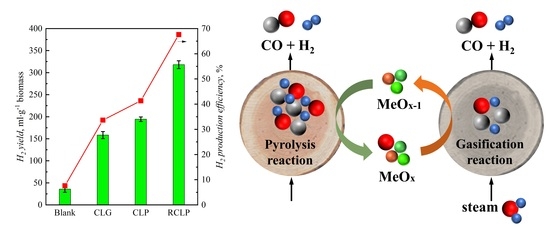
Graphical Abstract

1. Introduction

In recent years, the excessive consumption of fossil fuels has led to global energy shortages and a year-by-year increase in carbon dioxide emissions, which in turn has exacerbated climate change and associated environmental issues [1,2]. To reduce dependence on fossil fuels and address these challenges, it is imperative to develop clean and sustainable energy alternatives [3,4]. Hydrogen energy, characterized by its high energy density and zero-pollution nature, has attracted considerable attention as an excellent energy carrier. However, conventional hydrogen production methods, such as water electrolysis and coal conversion, suffer from high energy consumption and significant carbon emissions. Therefore, identifying suitable feedstocks for hydrogen production is of paramount importance. Biomass, as the only renewable organic carbon source on the earth, offers abundant resources and wide availability [5,6,7]. China, in particular, possesses substantial biomass resources, making biomass the fourth largest energy source after coal, oil, and natural gas. Among various biomass feedstocks, forest residues are especially promising, and converting them into hydrogen energy presents significant economic and environmental benefits [8,9].
Thermochemical conversion is the most commonly employed route for hydrogen production from biomass, with biomass gasification and bio-oil reforming being the primary methods. These processes utilize gasifying agents to supply oxygen and heat, thereby converting biomass into hydrogen [10,11,12,13,14]. However, the inherent properties of biomass, including high volatility, high moisture content, and high oxygen content, often lead to elevated levels of tar and carbon dioxide in the pyrolysis–gasification products, which compromise product purity and hydrogen yield. Consequently, processes such as catalytic deoxygenation and post-treatment are typically required to improve product quality and enhance hydrogen enrichment and utilization efficiency [15,16,17]. Although these approaches offer advantages such as high process maturity and stable material and process systems, they face challenges including tar formation, fluctuations in product purity, catalyst contamination, and high maintenance costs [18,19,20].
Chemical looping conversion technology has emerged as an efficient and environmentally friendly energy conversion method [21,22,23]. Its fundamental principle involves the use of oxygen carriers to perform redox cycles, avoiding direct contact between biomass and external oxygen sources. Biomass chemical looping hydrogen production includes biomass chemical looping gasification (CLG) and bio-oil reforming for hydrogen production (CLR) [24,25,26,27]. As for the CLG process, the pyrolysis, reforming, and gasification reaction are all concentrated within a single gasification reactor, making it difficult to control individual stages. As for the CLR process, the quality of bio-oil is a critical factor affecting hydrogen production. Bio-oil derived from conventional pyrolysis typically has a high oxygen content and poor quality, resulting in low hydrogen yield during reforming. Moreover, both CLG and CLR suffer from low biomass utilization efficiency.
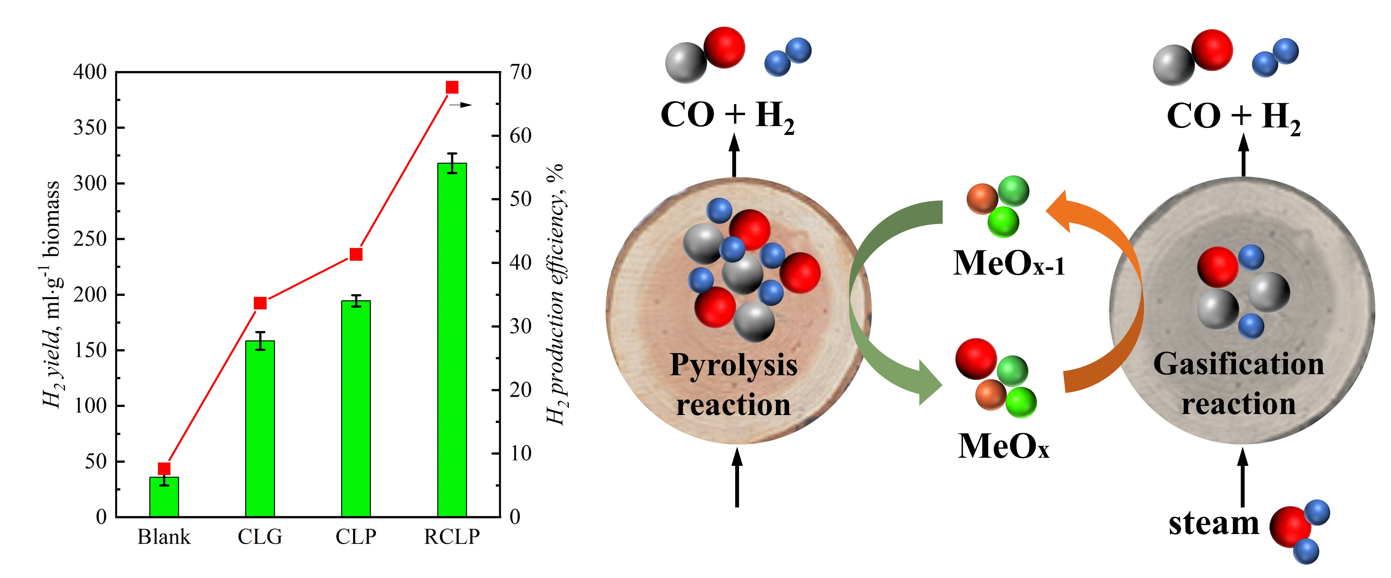
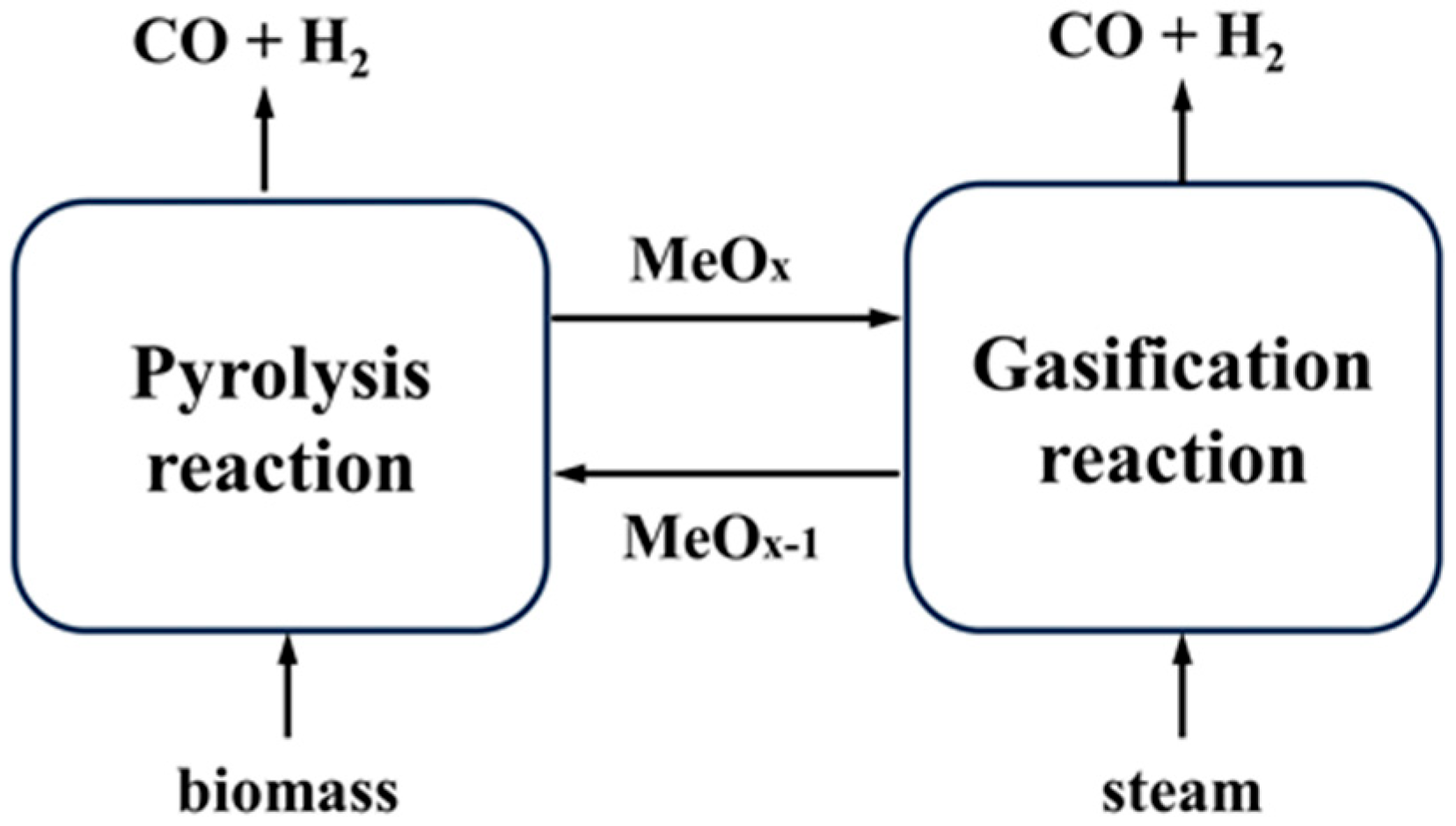
To address these limitations, our research group has introduced the concept of chemical looping staged conversion (CLSC), which decouples the gasification process into two distinct stages conducted at different temperatures, i.e., pyrolysis stage and gasification stage [28,29,30]. This decoupling enables precise control of pyrolysis conditions, optimization of product quality, and ultimately, the production of higher-quality bio-oil and syngas. By utilizing an oxidized oxygen carrier for biomass pyrolysis, namely chemical looping pyrolysis (CLPy), the pyrolysis efficiency of solid biomass is enhanced significantly. However, oxygen contained inherently in biomass and an oxygen carrier leads to excessive oxygen incorporation into the gas and liquid phases. The obtained bio-oil still requires further upgrading [31,32,33]. Furthermore, by altering the direction of the oxygen transfer, reverse chemical looping pyrolysis (RCLPy) was proposed, which utilizes a reduced oxygen carrier (Re–OC) to extract oxygen from the biomass feedstock during the pyrolysis stage and transfer it for the subsequent gasification stage [34]. Re–OC can not only decrease the oxygen content of bio-oils in situ via its oxidation reaction but also provide H2 for the in situ upgrading of bio-oils through hydrogen generation reactions between Re–OC and small-molecule oxygen-containing compounds. Furthermore, through the integration of oxygen carrying and catalytic cracking, this decoupled mechanism facilitates the efficient in situ utilization of oxygen and hydrogen inherent in the biomass for the production of a hydrogen-rich syngas. The schematic diagram of RCLPy for hydrogen production is presented in Figure 1. First, under pyrolysis conditions, biomass is directly decomposed into H2-rich syngas via the deoxygenation of the reduced oxygen carrier. Next, the oxidized oxygen carrier is reduced by the mixed char to achieve the regeneration of the reduced oxygen carrier at a higher temperature, accompanied by the production of clean syngas free of tar. This hydrogen production method still needs to be further verified.
In this study, we investigate the performance of RCLPy for hydrogen production using pine biomass as the feedstock. The deoxygenation capability, redox cycling performance, and catalytic hydrogen production activity of a Ca–Fe–Ni composite oxygen carrier are systematically evaluated through multiple pyrolysis–gasification cycles. The findings of this research are expected to open new avenues for efficient hydrogen production by enhancing the utilization of hydrogen inherently present in biomass.

2. Results and Discussion

2.1. Characterization of the Re–CaFeNix Oxygen Carrier

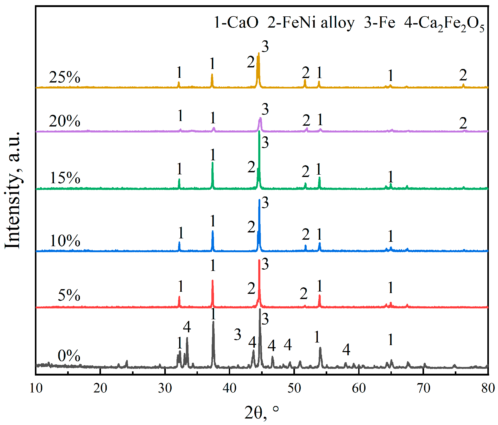
Figure 2 presents the XRD patterns of Re–CaFeNix oxygen carriers with different NiO doping amounts to explore the structural evolution induced by nickel incorporation. As a reference, the XRD pattern of the undoped reduced Ca–Fe oxygen carrier reveals three dominant crystalline phases: metallic iron (Fe, PDF# 04-003-7116), calcium oxide (CaO, PDF# 04-004-8985), and a portion of the unreduced Ca2Fe2O5 (PDF# 01-075-7773). This observation aligns well with a previous report on Ca–Fe-based oxygen carriers, primarily because of its relatively high thermodynamic stability [35]. Both CaO and Fe can remove oxygen and generate hydrogen through their oxidation reactions, returning to their oxidation state Ca2Fe2O5 [29]. Additionally, they can participate in catalytic reactions to crack the biomass and its products [36]. Upon the introduction of NiO, a new series of diffraction peaks emerges at approximately 43.7°, 51.0°, and 74.9°, which are well-matched with the characteristic reflections of the Ni–Fe alloy (PDF# 04-009-3507), confirming the successful formation of a bimetallic phase during the high-temperature reduction step. Importantly, no diffraction signals related to Ca2Fe2O5 are detectable in any of the Ni-doped oxygen carriers, indicating that NiO doping improves the reducibility of the Ca–Fe composites. Moreover, the addition of NiO leads to a reduction in the intensity of the CaO and Fe peaks. When the doping amount exceeds 15%, the intensities of both the CaO and Fe peaks decrease significantly. This is likely due to the interaction between Fe and Ni and the subsequent coverage of the CaO and Fe peaks by them.

2.2. Effect of the NiO Doping Amount on Hydrogen Production

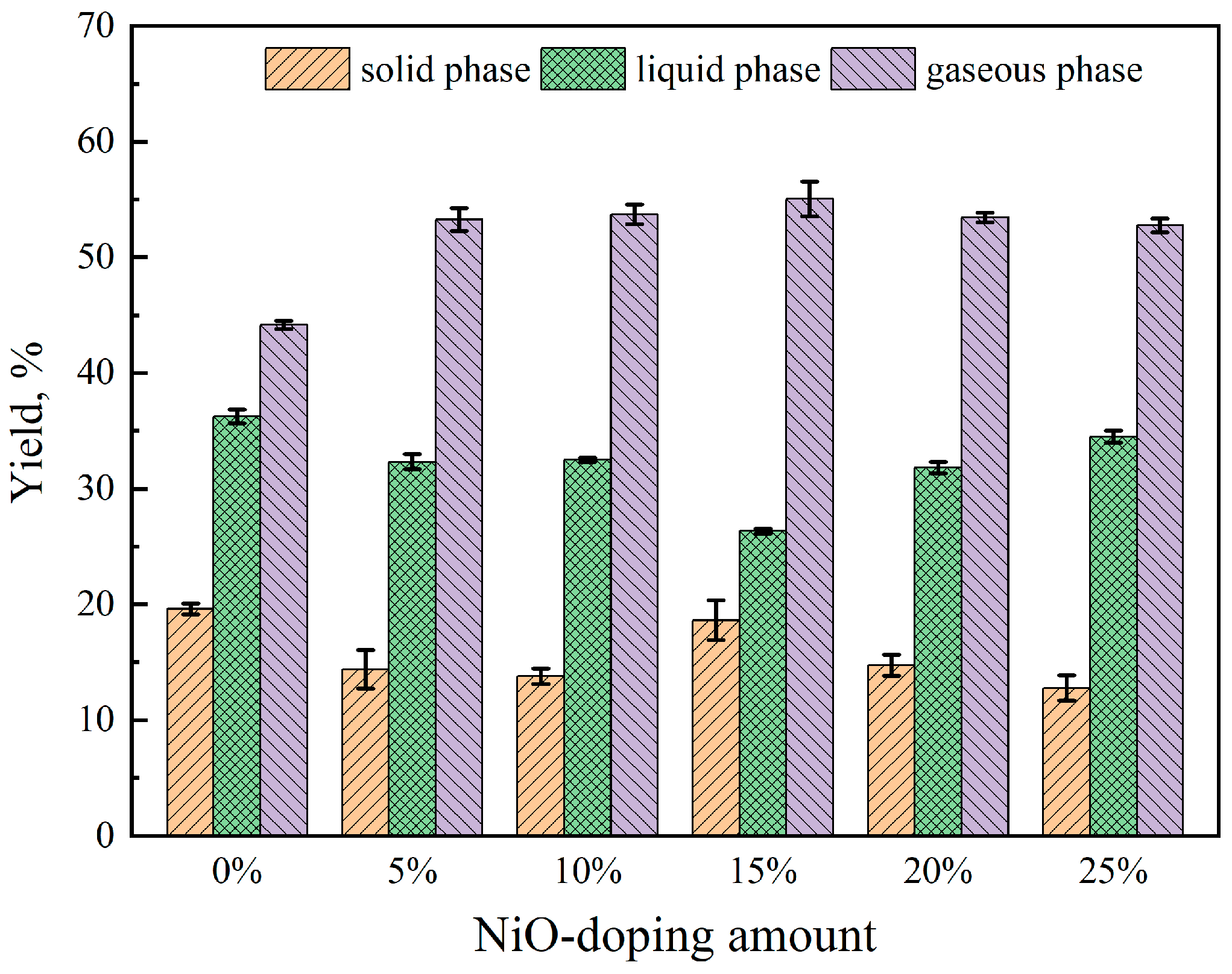
Due to the favorable catalytic activity of Ni in the cracking of biomass, as well as its excellent performance in tar reforming, Ni was selected as a dopant for the Ca2Fe2O5 oxygen carrier at five different doping levels, namely 5 wt.%, 10 wt.%, 15 wt.%, 20 wt.%, and 25 wt.% to systematically evaluate the effect of Ni content on the pyrolysis–gasification performance. The effect of NiO doping amount on the distribution of gas, liquid, and solid products is presented in Figure 3. For comparison, the reduced Ca2Fe2O5 without NiO doping exhibited high solid and liquid yields but a low gaseous yield, indicating its relatively weak cracking capability. This suggests that the unmodified Ca2Fe2O5 oxygen carrier is less effective in promoting the conversion of biomass pyrolysis intermediates into gaseous products. Upon NiO doping, a significant increase in gaseous yield was observed, while the liquid yield initially decreased and then increased with increasing NiO content. This trend indicates that an appropriate amount of NiO doping enhances the cracking of bio-oil into light gases, whereas excessive NiO may lead to adverse effects such as particle agglomeration or surface coverage. Among the five doping levels, the Re–CaFeNi15 oxygen carrier demonstrated the best performance, achieving the highest gaseous yield of 55.0 wt.% and the lowest liquid yield of 26.3 wt.%. Meanwhile, a solid yield of 18.6 wt.% was also observed, which is primarily attributed to the transfer of oxygen from the biomass to the reduced oxygen carrier via oxidation reactions. This oxygen transfer reduces the oxygen content in the pyrolyzed products, which further contributes to the generation of hydrogen.
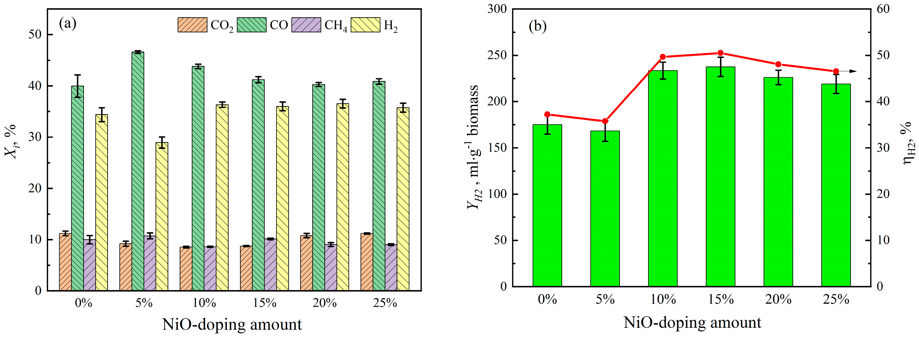
The effect of the NiO doping amount on the relative contents of gaseous products is depicted in Figure 4a. For the unmodified Ca2Fe2O5 oxygen carrier, a high content of both CO and H2 was detected, which can attributed to the outstanding selective oxidation of the reduced Ca2Fe2O5, a state mainly composed of CaO and Fe. Upon the addition of 5 wt.% NiO, the relative content of CO increased significantly because of the catalytic cracking of pyrolyzed volatiles over Ni-active sites. Conversely, the H2 content showed a relative decline. As the NiO doping amount further increased, the CO content showed a slight decreasing trend, while the H2 content remained relatively stable at approximately 36 vol.%. The hydrogen yield and hydrogen production efficiency as functions of NiO-doping amount are shown in Figure 4b. Both parameters exhibited a clear trend of first increasing and then decreasing as the NiO doping amount increased from 5 wt.% to 25 wt.%. At the optimal doping level of 15 wt.%, a hydrogen yield of 237.6 mL·g−1 biomass and a hydrogen production efficiency of 50% were achieved. This indicates that more than half of the hydrogen element inherently present in the biomass was released in the form of molecular hydrogen rather than as steam or other hydrogen-containing compounds. This phenomenon underscores a key advantage of the reverse chemical looping process over conventional thermochemical conversion methods, namely the enhanced in-situ utilization of hydrogen intrinsic to the biomass.

2.3. Effect of Re–OC/B Mass Ratio on the Hydrogen Production

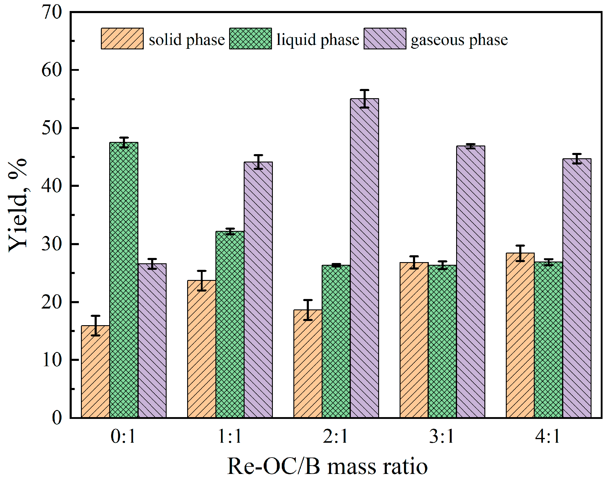
Based on the results discussed above, the reduced oxygen carrier doped with 15 wt.% NiO was selected for further investigation. The effect of the reduced oxygen carrier-to-biomass (Re–OC/B) mass ratio on the distribution of gas, liquid, and solid products is illustrated in Figure 5. As the Re–OC/B mass ratio increases, the liquid yield decreases substantially, while the solid yield exhibits a slight increasing trend. The gaseous yield initially increases and then decreases, reaching a maximum of 55.0 wt.% at an Re–OC/B mass ratio of 2:1. In the absence of an oxygen carrier, the liquid yield is as high as 47.5 wt.%, which is consistent with reported values for direct biomass pyrolysis [28]. With the introduction of the oxygen carrier, volatiles undergo an enhanced decomposition into small molecules, leading to a marked reduction in both liquid and solid yields, accompanied by a corresponding increase in gas yield. A higher Re-OC/B mass ratio provides more reduction sites and catalytic sites, thereby facilitating oxygen transfer from volatiles to the reduced oxygen carrier and promoting the cracking of intermediates into small gaseous molecules. At an Re–OC/B mass ratio of 1:1, the available catalytic site appears insufficient to crack the liquid products into gaseous components. When the Re-OC/B mass ratio exceeds 2:1, the liquid yield stabilizes, whereas the gaseous yield begins to decline, indicating sustained deoxygenation capacity. Considering both deoxygenation and catalytic performance, the optimal Re-OC/B mass ratio is determined to be 2:1.
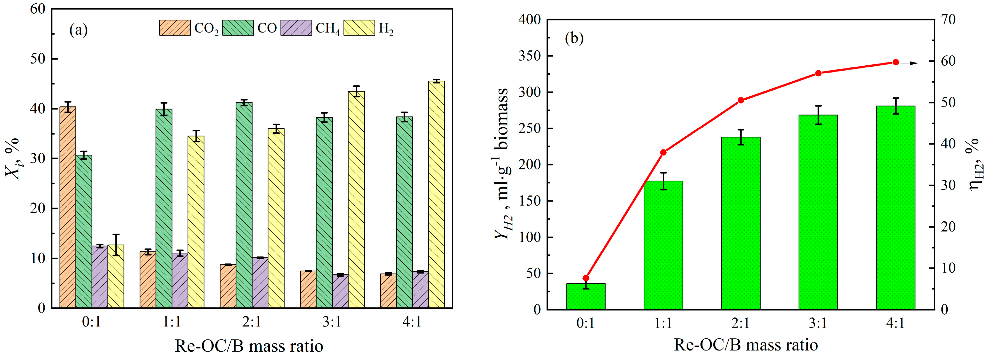
The effect of the Re-OC/B mass ratio on the relative contents of gaseous products is shown in Figure 6a. In the absence of the reduced oxygen carrier, the relative content of CO2 is as high as 40.4 vol.%, while that of H2 is as low as 12.7 vol.%. During conventional pyrolysis, most of the oxygen contained in biomass is released in the form of CO2 and H2O, which significantly limits the utilization efficiency of both the oxygen and hydrogen elements. With the introduction of the reduced oxygen carrier, the relative contents of CO2 decreased sharply to 6.89 vol.%, while that of H2 increased dramatically, reaching 45.5 vol.% at Re–OC/B mass ratio of 4:1. Under this condition, the total contents of syngas (CO + CH4 + H2) reached as high as 91.0 vol.%. Moreover, the increase in CO content was likely due to the partial deoxygenation of CO2, while the decrease in CH4 content can be attributed to its catalytic reforming over the active sites of the reduced oxygen carrier. The hydrogen yield and hydrogen production efficiency as functions of the Re–OC/B mass ratio are shown in Figure 6b. Both parameters exhibited a clear trend of first increasing and then decreasing as the Re–OC/B mass ratio increased from 0 to 4:1. The hydrogen yield and the hydrogen production efficiency increased significantly from 35.8 mL·g−1 biomass and 7.6% without an oxygen carrier to 280.2 mL·g−1 biomass and 59.7% with an Re–OC/B mass ratio of 4:1, respectively. The above results demonstrate that under optimized conditions, the majority of the hydrogen and carbon elements inherent in the biomass can be efficiently released in the form of H2 and CO, respectively, highlighting the effectiveness of the reverse chemical looping process in promoting the production of high-quality syngas.

2.4. Gasification Performance of Pyrolysis Char

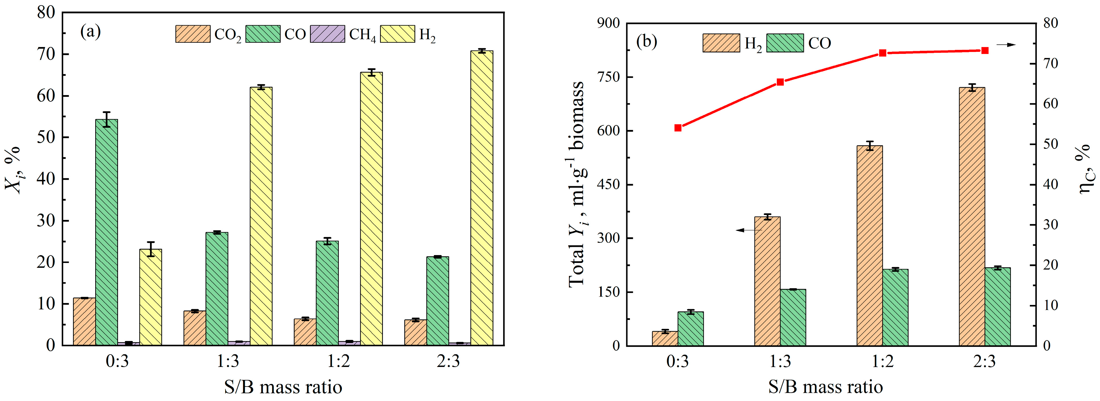
Further elevation of the reaction temperature not only promotes deep cracking of biomass but also initiates the chemical looping gasification (CLG) reaction. At a typical CLG temperature of 850 °C, the oxidized reduced oxygen carrier (Re–OC) could release oxygen via reactions with biomass. To regenerate the reduced oxygen carrier, the gasification stage was conducted between the oxygen carrier and bio-char, both with and without steam. The gaseous composition of the gasification products under different steam-to-biomass (S/B) mass ratios is presented in Figure 7a. In the absence of steam, CO accounted for 54.3 vol.% of the gasification gas, primarily originating from the further decomposition of char and the reaction between the oxygen carrier and char. Upon the introduction of steam as a gasifying agent, the relative content of H2 in the gasification gas increased substantially, rising from 62.1 vol.% at an S/B mass ratio of 1:3 to 70.8 vol.% at an S/B mass ratio of 2:3. This enhancement can be attributed to two concurrent mechanisms: the char–steam gasification reaction and the reaction between unreacted oxygen carriers and steam. Notably, steam simultaneously provides an external source of both hydrogen and oxygen, facilitating hydrogen generation and the gasification of carbon derived from char. The yields of CO and H2, along with the total carbon balance of gaseous products under different S/B mass ratios, are presented in Figure 7b. At an S/B mass ratio of 2:3, the yields of H2 and CO during the gasification stage reached 721 mL·g−1 biomass and 217 mL·g−1 biomass, respectively, which are 18 times and 2.3 times higher than those achieved without a gasifying agent. The removal of hydrogen and oxygen elements during the pyrolysis stage leaves a greater proportion of carbon available for gasification, thereby generating more syngas.
It is particularly noteworthy that, because the oxygen carrier has already fixed a substantial amount of oxygen from the biomass via deoxygenation reactions during the pyrolysis stage, the external oxygen demand in the gasification stage is significantly reduced. Consequently, only a relatively low S/B mass ratio is required to achieve complete gasification of the pyrolysis char, thereby improving the overall material and energy utilization efficiency of the entire process. Based on the carbon balance, an S/B mass ratio of 1:2 is sufficient to meet the gasification requirement. The further increase in H2 production observed at an S/B mass ratio of 2:3 is attributed to the reaction between the metal species in the oxygen carrier and steam. In the subsequent research, an S/B mass ratio of 1:3 was employed.

2.5. Comparison of Different Chemical Looping Processes

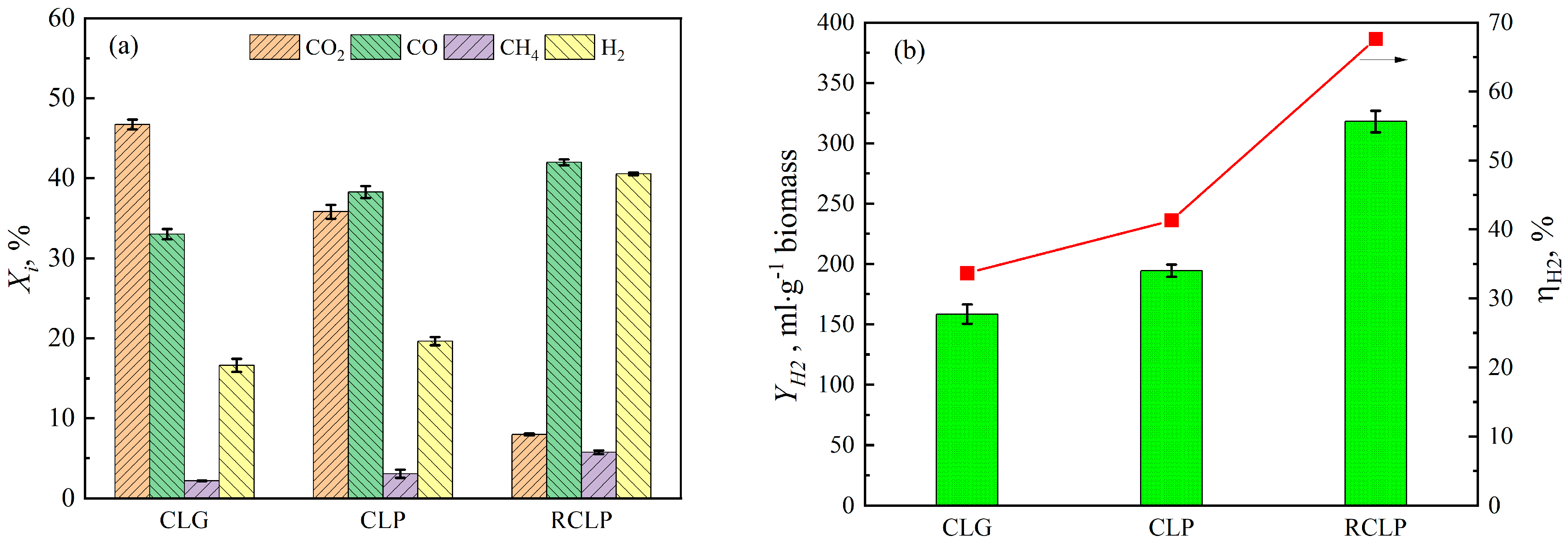
To elucidate the advantages of the RCLPy process, two typical chemical looping processes for hydrogen generation, namely CLG and CLPy, were investigated for comparison. The CLG process, employing the oxidized CaFeNi15 oxygen carrier, was carried out at a gasification temperature of 850 °C without the use of a gasifying agent. In contrast, the CLPy process utilized the Ox–CaFeNi15 oxygen carrier at the same pyrolysis temperature as that of RCLPy. The performance of these three processes was evaluated in terms of both gaseous product distribution and hydrogen production performance. As shown in Figure 8a, both CLG and CLPy, which employ an oxidized oxygen carrier for biomass gasification and pyrolysis, respectively, produced higher amounts of CO2 and lower amounts of H2 compared to RCLPy. This observation can be attributed to the combined effects of oxidation and catalytic cracking induced by the oxygen carrier. In contrast, the RCLPy process exhibited a markedly different product distribution. Specifically, the relative content of CO2 decreased sharply to 8.0 vol.% in RCLPy, down from 46.7 vol.% in CLG and 35.8 vol.% in CLPy. Meanwhile, the H2 content increased remarkably to 40.5 vol.%, compared to 16.6 vol.% for CLG and 19.6 vol.% for CLPy.
Figure 8b further highlights the superior hydrogen production performance of RCLPy. The hydrogen yield achieved by RCLPy reached 318 mL·g−1 biomass, substantially higher than the 158.4 mL·g−1 biomass obtained from CLG and the 194.4 mL·g−1 biomass from CLPy. Correspondingly, the hydrogen production efficiency of RCLPy reached 67.6%, far exceeding the efficiencies of CLG (33.7%) and CLPy (41.3%). These results clearly demonstrate that the RCLPy process significantly outperforms conventional chemical looping approaches in terms of both hydrogen yield and efficiency, owing to its unique deoxygenation mechanism that promotes the in situ utilization of hydrogen inherent in the biomass.

2.6. Pyrolysis–Gasification Cyclic Reaction Performance

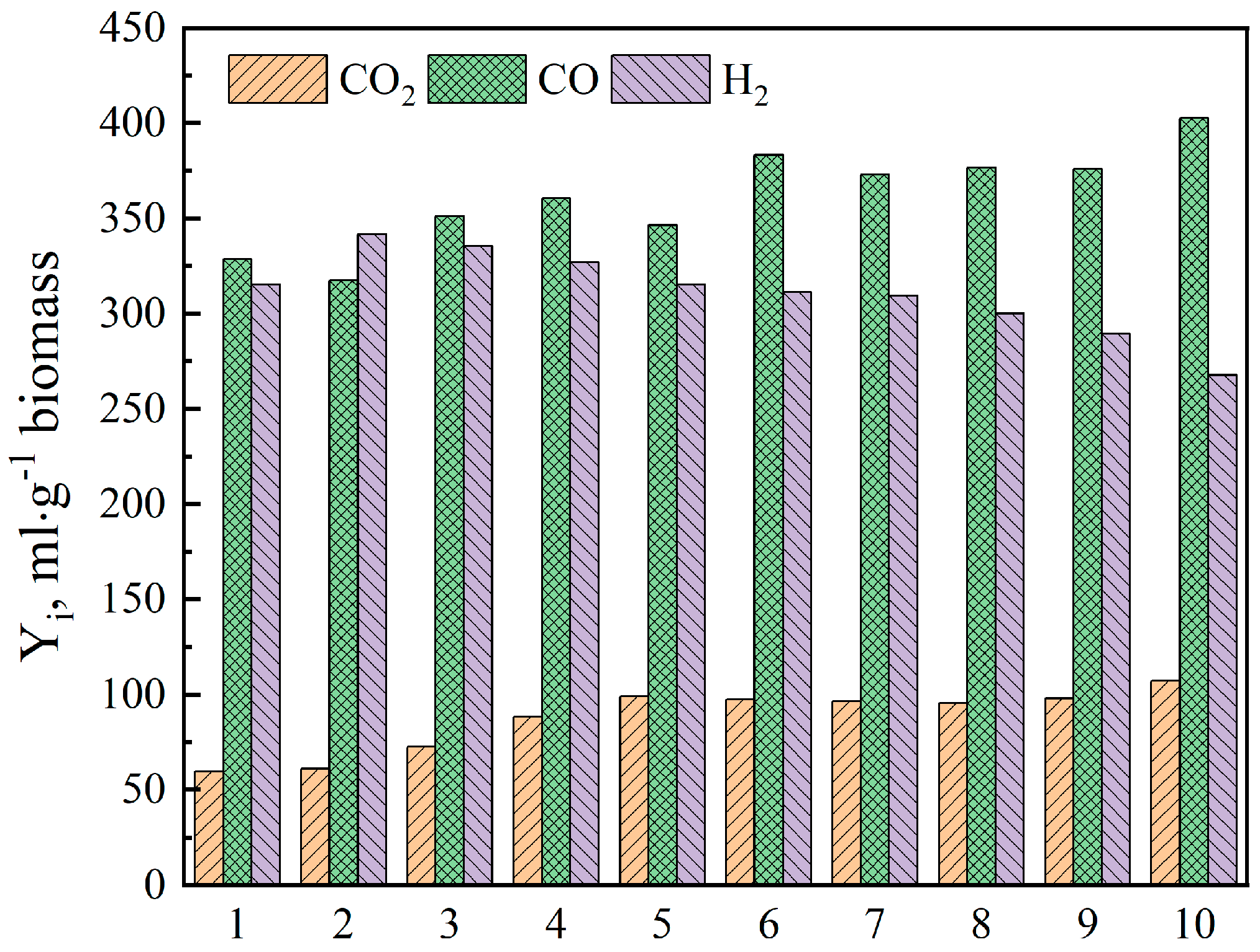
To evaluate the catalytic activity and structural stability of the reduced CaFeNi15 oxygen carrier over multiple reaction cycles, ten consecutive pyrolysis–gasification cyclic experiments were conducted. The hydrogen production performance as a function of cycle number is presented in Figure 9. As the number of cycles increased, the yields of both CO2 and CO exhibited a gradual upward trend. In contrast, the H2 yield first increased and then decreased, reaching its highest value at the second cycle. This observation suggests that the deoxygenation capability of the oxygen carrier gradually weakened with repeated cycling, as evidenced by the simultaneous decrease in H2 yield and increase in CO2 yield. Meanwhile, the progressive increase in CO yield may indicate an enhancement in the catalytic performance of the Re–CaFeNi15 oxygen carrier, potentially due to the activation of certain surface sites or structural rearrangements induced by repeated redox cycling. Overall, these results demonstrate that while the CaFeNi15 oxygen carrier maintains reasonable catalytic activity over ten cycles, its deoxygenation performance shows signs of degradation, highlighting the need for further optimization to improve long-term cyclic stability.
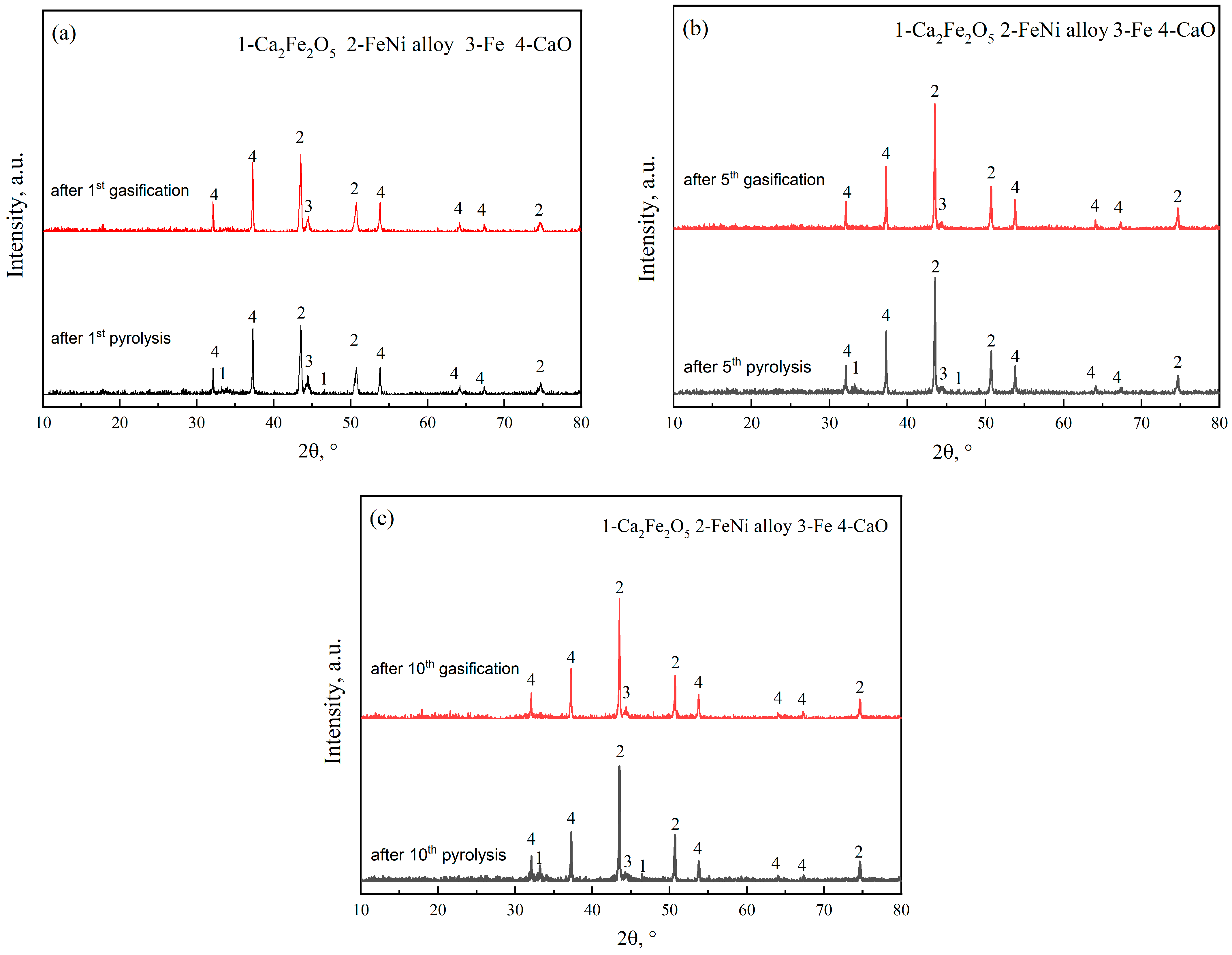
The XRD patterns of the Re–CaFeNi15 oxygen carrier after the first pyrolysis, first gasification, fifth pyrolysis, fifth gasification, tenth pyrolysis, and tenth gasification cycles are presented in Figure 10. Compared with the fresh reduced oxygen carrier, the XRD patterns reveal that the intensity of the Fe phase was significantly weakened, while that of the Fe–Ni alloy phase increased markedly. The Fe–Ni alloy is known to facilitate both the decomposition of biomass and the catalytic cracking of bio-oil into light gases, thereby contributing to enhanced gas yield and hydrogen production. After the first, fifth, and tenth pyrolysis cycles, the Ca2Fe2O5 phase was detected, and its diffraction peak intensity increased progressively with the number of cycles. The formation of the Ca2Fe2O5 phase during the pyrolysis stage indicates the transfer of oxygen from the biomass to the reduced oxygen carrier, reflecting the deoxygenation function of the oxygen carrier. In contrast, after the first, fifth, and tenth gasification cycles, the Ca2Fe2O5 phase disappeared, which can be attributed to the release of lattice oxygen for the oxidation of char during the gasification stage. The redox transformation of Ca2Fe2O5 throughout the pyrolysis and gasification stages demonstrates that the reduced oxygen carrier possesses excellent redox cycling performance. These results further confirm the feasibility of the RCLPy process for sustainable hydrogen production from biomass.
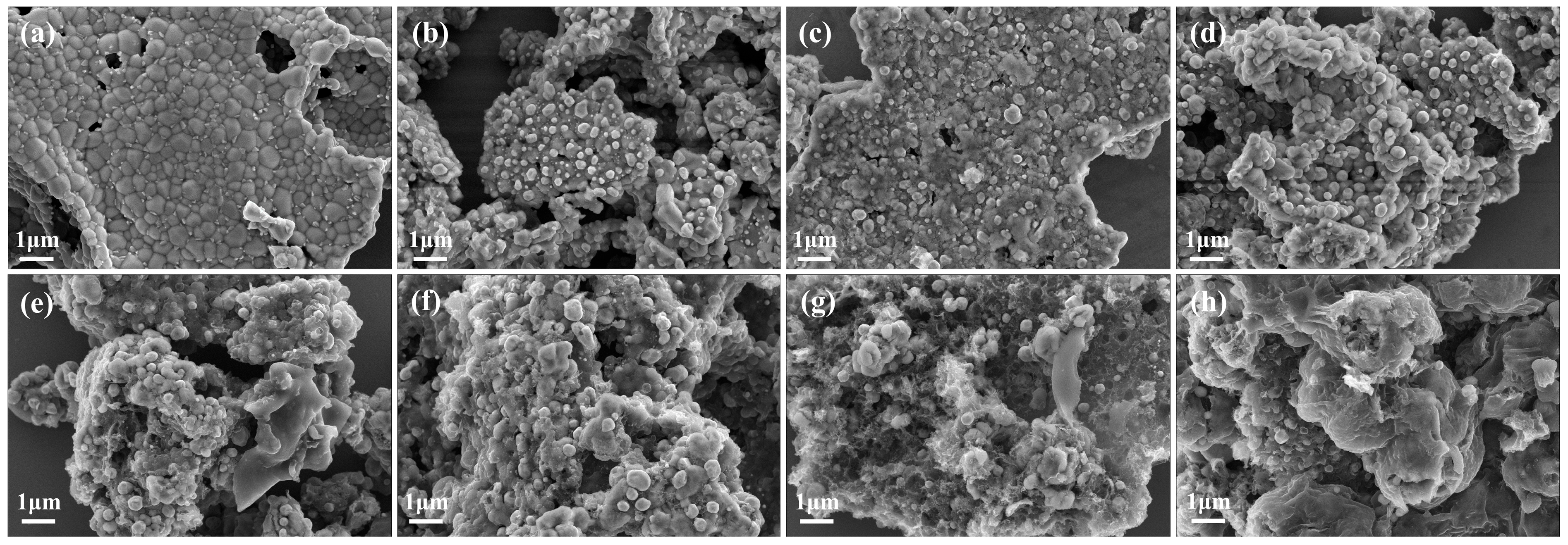
The surface morphologies of the reduced CaFeNi15 oxygen carrier after the first pyrolysis, first gasification, fifth pyrolysis, fifth gasification, tenth pyrolysis, and tenth gasification cycles are presented in Figure 11. The fresh oxygen carrier in its oxidized state exhibited a compact structure composed of densely packed particles. After reduction with H2, a uniform dispersion of Fe and Fe–Ni alloy particles appeared on the surface, accompanied by an increase in porosity. Following the first pyrolysis cycle, the oxygen carrier surface became compact, which can be attributed to partial oxidation of the oxygen carrier and surface coverage by residual char. After the first gasification cycle, the surface morphology transformed into a porous structure, with Fe and Fe–Ni alloy particles uniformly distributed across the surface. This porous morphology was largely maintained after the fifth pyrolysis and fifth gasification cycles, indicating reasonable structural stability during the initial cycles. However, after the tenth pyrolysis and tenth gasification cycles, significant morphological changes were observed. The porous structure and uniform particle distribution disappeared, likely due to both the accumulation of unconverted carbon on the surface and the agglomeration of metal particles. These morphological deteriorations are consistent with the observed decline in hydrogen yield and deoxygenation performance after multiple cycles, as discussed previously. The degradation of the oxygen carrier structure underscores the need for further optimization of oxygen carrier design to enhance long-term cyclic stability.

3. Materials and Methods

3.1. Material Preparation and Characterization

Ca–Fe–Ni composite oxygen carriers were prepared via a mechanical grinding and calcination method. The precursors, including CaCO3, Fe2O3, and NiO, were mixed at the desired molar ratio and ground for 60 min. The obtained mixture was then calcined in a muffle furnace at 300 °C for 2 h, followed by further calcination at 900 °C for 12 h. After cooling to room temperature, the samples were crushed, sieved, and labeled. The molar ratio of Ca and Fe was set as 1:1 to obtain Ca2Fe2O5, owing to its excellent redox performance [35]. NiO was added at mass ratios of 5 wt.%, 10 wt.%, 15 wt.%, 20 wt.% and 25 wt.% relative to the prepared oxygen carrier, and the resulting samples were designated as Ox–CaFeNix (x = 5, 10, 15, 20 and 25). Prior to the experiments, the as-prepared composite oxygen carrier was pre-reduced under a H2 atmosphere of 100 mL/min at 850 °C for half an hour to obtain their reduced forms, which were correspondingly denoted as Re–CaFeNix (x = 5, 10, 15, 20 and 25). Quartz sand was used instead for comparison experiments.
The proximate, ultimate and component analyses of pine wood biomass are summarized in Table 1. The elemental composition of the biomass was determined using an elemental analyzer (Elementar UNICUBE, Langenselbold, Germany), and the oxygen content was calculated by difference. The proximate analysis was performed using a thermogravimetric analyzer (NETZSCH STA409PC, Selb, Germany). Component analysis was conducted in accordance with the Chinese energy industry standard NB/T 34057.5-2017 [37].
The phase composition of the fresh, reduced, and spent composite oxygen carriers was analyzed by an X-ray diffractometer (XRD, Rigaku SmartLab SE, Akishima, Japan) with Cu Kα radiation. The diffraction angle (2θ) ranged from 10° to 80°. All XRD patterns were analyzed using Jade 9 software. The surface morphology of the composite oxygen carriers was characterized using a scanning electron microscope (SEM, Zeiss Sigma 500, Jena, Germany).

3.2. Experimental Setup and Evaluation

Pyrolysis–gasification experiments were conducted in a fixed-bed reactor. The detailed procedure was as follows. (1) In the pyrolysis stage, the quartz reactor was firstly heated to the specified temperature (600, 650, 700, 750, 800 °C) under an argon flow of 100 mL/min. Once the temperature became stable, the mixed sample consisting of 3 g biomass and 3–12 g oxygen carrier, which was placed at the upper end of the reactor, was swiftly pushed into the heating zone. Liquid products were collected using an absorption bottle filling with isopropanol. The pyrolysis gases were measured with a wet gas meter and subsequently collected in a gas bag for gas chromatography (GC) analysis. The entire pyrolysis process endured for 30 min. The yield of the liquid phase was determined by weighing, the yield of the gas phase was calculated based on the gas volume and composition, and the yield of the solid phase was obtained by the difference method. (2) Next was the gasification stage, where after pyrolysis, the mixed sample was pulled from the heating zone, and the reactor was further heated to 850 °C. When the temperature reached stability, the pyrolyzed sample was reintroduced into the heating zone. The volume of the gas was measured using a wet gas meter and then collected in a gas bag for GC analysis. The gasification experiment lasted for 40 min. After the completion of the experiment, the reaction products were removed from the heating zone, the furnace heating was stopped, and the sample was cooled to room temperature under an argon atmosphere. (3) For the cyclic experiment tests, another 3 g of fresh pine biomass was added to the post-reaction solid mixture, and the pyrolysis–gasification procedure described above was repeated.
The relative contents of each component (Xi) in the pyrolysis gas and gasifying gas were determined by Equation (1), and the yield of hydrogen (YH2) and hydrogen production efficiency (ηH2) was calculated by Equations (2) and (3), respectively.
X i = C i C i   ,   i = CO 2 ,   CO ,   CH 4 ,   H 2 ,   N 2 ,   C n
Y H 2 = V × X H 2 × M H 2 22.4 × m b i o m a s s
η H 2 = Y H 2 Y H 2 , b i o m a s s

4. Conclusions

In this study, Ca–Fe–Ni composite oxygen carriers were successfully synthesized and applied in the reverse chemical looping pyrolysis (RCLPy) of pine biomass. The main conclusions are summarized as follows: (1) the reduced Ca–Fe–Ni oxygen carrier exhibited strong deoxygenation performance, reducing the CO2 content in pyrolysis gas from 40.4 vol.% to 6.89 vol.%, with the total contents of syngas (CO + CH4 + H2) reaching as high as 91.0 vol.%. (2) Ni doping substantially enhanced catalytic cracking via the formation of a Ni–Fe alloy, with the Re–CaFeNi15 showing the best performance of 55.0 wt.% gaseous yield and hydrogen production efficiency up to 67.6%. (3) Compared to conventional chemical looping gasification (CLG) and chemical looping pyrolysis (CLPy) using an oxidized oxygen carrier for biomass conversion, the RCLPy process produces nearly twice the hydrogen yield and hydrogen production efficiency owing to its unique deoxygenation mechanism that promotes in situ utilization of inherent biomass hydrogen. Overall, the RCLPy process using reduced Ca–Fe–Ni composite oxygen carriers offers a promising route for efficient hydrogen production with high syngas purity and low CO2 emissions. Future efforts should focus on developing oxygen carriers with enhanced cyclic stability.

Author Contributions

Conceptualization, Y.L.; methodology, Y.L. and L.Z.; software, L.Z., X.J. and J.W.; validation, Y.L., J.W. and J.R.; formal analysis, X.J. and S.S.; investigation, L.Z. and J.R.; resources, L.Z. and X.J.; data curation, Y.L. and J.R.; writing—original draft preparation, L.Z.; writing—review and editing, Y.L. and J.W.; visualization, Y.L. and S.S.; supervision, Y.L.; project administration, Y.L.; funding acquisition, Y.L. All authors have read and agreed to the published version of the manuscript.

Funding

This research was funded by the National Natural Science Foundation of China (Grant No. 22479084) and Shandong Provincial Natural Science Foundation (Grant No. ZR2025MS739).

Data Availability Statement

The original contributions presented in this study are included in the article. Further inquiries can be directed to the corresponding author.

Conflicts of Interest

The authors declare no conflicts of interest.

Abbreviations

The following abbreviations are used in this manuscript:
CLGChemical Looping Gasification
CLPyChemical Looping Pyrolysis
RCLPyReverse Chemical looping Pyrolysis

References

  1. Lu, H.; Xie, R.; Almoallim, H.S.; Alharbi, S.A.; Jhanani, G.K.; Praveenkumar, T.R.; Anderson, A.; Xia, C. Utilization of the Nannochloropsis microalgae biochar via microwave assisted pyrolysis on the mixed biomass fuel pellets. Environ. Res. 2023, 231, 116078. [Google Scholar] [CrossRef]
  2. Ang, T.-Z.; Salem, M.; Kamarol, M.; Das, H.S.; Nazari, M.A.; Prabaharan, N. A comprehensive study of renewable energy sources: Classifications, challenges and suggestions. Energy Strategy Rev. 2022, 43, 100939. [Google Scholar] [CrossRef]
  3. Kumar, A.; Reddy, S.N. Subcritical and supercritical water in-situ gasification of metal (Ni/Ru/Fe) impregnated banana pseudo-stem for hydrogen rich fuel gas mixture. Int. J. Hydrogen Energy 2020, 45, 18348–18362. [Google Scholar] [CrossRef]
  4. Ishaq, H.; Dincer, I. Comparative assessment of renewable energy-based hydrogen production methods. Renew. Sustain. Energy Rev. 2021, 135, 110192. [Google Scholar] [CrossRef]
  5. Squadrito, G.; Maggio, G.; Nicita, A. The green hydrogen revolution. Renew. Energy 2023, 216, 119041. [Google Scholar] [CrossRef]
  6. Capurso, T.; Stefanizzi, M.; Torresi, M.; Camporeale, S.M. Perspective of the role of hydrogen in the 21st century energy transition. Energy Convers. Manag. 2022, 251, 114898. [Google Scholar] [CrossRef]
  7. Guo, J.-X.; Tan, X.; Zhu, K.; Gu, B. Integrated management of mixed biomass for hydrogen production from gasification. Chem. Eng. Res. Des. 2022, 179, 41–55. [Google Scholar] [CrossRef]
  8. Li, J.; Xiong, Z.; Zeng, K.; Zhong, D.; Zhang, X.; Chen, W.; Nzihou, A.; Flamant, G.; Yang, H.; Chen, H. Characteristics and evolution of nitrogen in the heavy components of algae pyrolysis bio-oil. Environ. Sci. Technol. 2021, 55, 6373–6385. [Google Scholar] [CrossRef]
  9. Ozbas, E.E.; Aksu, D.; Ongen, A.; Aydin, M.A.; Ozcan, H.K. Hydrogen production via biomass gasification, and modeling by supervised machine learning algorithms. Int. J. Hydrogen Energy 2019, 44, 17260–17268. [Google Scholar] [CrossRef]
  10. Md, W.I. Effect of different gasifying agents (steam, H2O2, oxygen, CO2, and air) on gasification parameters. Int. J. Hydrogen Energy 2020, 45, 31760–31774. [Google Scholar]
  11. Mohan, S.V. Chapter 1—Sustainable Hydrogen Production: An Introduction. In Biohydrogen, 2nd ed.; Elsevier: Amsterdam, The Netherlands, 2019; pp. 1–23. [Google Scholar]
  12. Ian, W.; Phillip, C.; Harvey, B. Integration of heterogeneous and biochemical catalysis for production of fuels and chemicals from biomass. Curr. Opin. Biotechnol. 2017, 45, 127–135. [Google Scholar] [CrossRef]
  13. Zhang, S.; Liang, D.; Li, X.; Fan, Y.; Huang, H.; He, X.; Wang, L.; Li, Z.; Yong, D. Study on the mechanism of hydrogen production by catalytic pyrolysis of bagasse over CaO/Na2CO3. Prog. React. Kinet. Mech. 2026, 51, E002. [Google Scholar] [CrossRef]
  14. Solarte-Toro, J.C.; González-Aguirre, J.A.; Giraldo, J.A.P.; Alzate, C.A.C. Thermochemical processing of woody biomass: A review focused on energy-driven applications and catalytic upgrading. Renew. Sustain. Energy Rev. 2021, 136, 110736. [Google Scholar] [CrossRef]
  15. Remiro, A.; Ochoa, A.; Arandia, A.; Castaño, P.; Bilbao, J.; Gayubo, A.G. On the dynamics and reversibility of the deactivation of a Rh/CeO2ZrO2 catalyst in raw bio-oil steam reforming. Int. J. Hydrogen Energy 2019, 44, 2620–2632. [Google Scholar] [CrossRef]
  16. Antonio, T.; Fabrizio, O. 1-Biomass conversion: General information, chemistry, and processes. In Advances in Bioenergy and Microfluidic Applications; Elsevier: Amsterdam, The Netherlands, 2021; pp. 3–39. [Google Scholar]
  17. Caroline, C.S.; Klaus, R.; Anna, Z.; Krause, B.; Otto, T.; Rapp, M.; Dahmen, N. Hydrotreatment of fast pyrolysis bio-oil fractions over nickel-based catalyst. Top. Catal. 2018, 61, 1769–1782. [Google Scholar]
  18. Seow, Y.X.; Tan, Y.H.; Mubarak, N.M.; Kansedo, J.; Khalid, M.; Ibrahim, M.L.; Ghasemi, M. A review on biochar production from different biomass wastes by recent carbonization technologies and its sustainable applications. J. Environ. Chem. Eng. 2022, 10, 107017. [Google Scholar] [CrossRef]
  19. Shahbaz, M.; Al-Ansari, T.; Aslam, M.; Khan, Z.; Inayat, A.; Athar, M.; Naqvi, S.R.; Ahmed, M.A.; McKay, G. A state of the art review on biomass processing and conversion technologies to produce hydrogen and its recovery via membrane separation. Int. J. Hydrogen Energy 2020, 45, 15166–15195. [Google Scholar] [CrossRef]
  20. Giakoumakis, G.; Sidiras, D. Production and storage of hydrogen from biomass and other sources: Technologies and policies. Energies 2025, 18, 650. [Google Scholar] [CrossRef]
  21. Zhao, X.; Zhou, H.; Sikarwar, V.S.; Zhao, M.; Park, A.A.; Fennell, P.S.; Shen, L.H.; Fan, L.S. Biomass-based chemical looping technologies: The good, the bad and the future. Energy Environ. Sci. 2017, 10, 1885–1910. [Google Scholar] [CrossRef]
  22. Luo, M.; Yang Yi, Y.; Wang, S.; Wang, Z.; Du, M.; Pan, J.; Wang, Q. Review of hydrogen production using chemical-looping technology. Renew. Sustain. Energy Rev. 2018, 81, 3186–3214. [Google Scholar] [CrossRef]
  23. Qiu, Y.; Zeng, D.; Xiao, R. Hydrogen production from biomass-based chemical looping: A critical review and perspectives. Energy Fuels 2024, 38, 13819−13836. [Google Scholar] [CrossRef]
  24. Guo, Q.J.; Cheng, Y.; Liu, Y.Z.; Jia, W.H.; Ryu, H.J. Coal chemical looping gasification for syngas generation using an iron-based oxygen carrier. Ind. Eng. Chem. Res. 2014, 53, 78–86. [Google Scholar] [CrossRef]
  25. Huang, Z.; He, F.; Zheng, A.; Zhao, K.; Chang, S.; Zhao, Z. Synthesis gas production from biomass gasification using steam coupling with natural hematite as oxygen carrier. Energy 2013, 53, 244–251. [Google Scholar] [CrossRef]
  26. Huang, Z.; Zhang, Y.; Fu, J.J.; Yu, L.H. Chemical looping gasification of biomass char using iron ore as an oxygen carrier. Int. J. Hydrogen Energy 2016, 41, 17871–17883. [Google Scholar] [CrossRef]
  27. Liu, G.C.; Liao, Y.F.; Wu, Y.T.; Ma, X.Q.; Chen, L.M. Characteristics of microalgae gasification through chemical looping in the presence of steam. Int. J. Hydrogen Energy 2017, 42, 22730–22742. [Google Scholar] [CrossRef]
  28. Liu, Y.Z.; Wang, T.; Zhang, X.T.; Hu, X.; Liu, T.; Guo, Q. Chemical looping staged conversion of microalgae with calcium ferrite as oxygen carrier: Pyrolysis and gasification characteristics. J. Anal. Appl. Pyrolysis 2021, 156, 105129. [Google Scholar] [CrossRef]
  29. Liu, Y.Z.; Liu, J.J.; Wang, T.; Zhang, X.; Wang, L.; Hu, X.; Guo, Q. Co-production of upgraded bio-oils and H2-rich gas from microalgae via chemical looping pyrolysis. Int. J. Hydrogen Energy 2021, 46, 24942–24955. [Google Scholar] [CrossRef]
  30. Gao, X.Y.; He, X.; Liu, Y.Z.; Zhang, X.; Hu, X.; Guo, Q. Chemical looping pyrolysis-gasification staged conversion of microalgae biomass with Ca-Fe composite oxygen carrier. Int. J. Greenh. Gas Control 2023, 127, 103941. [Google Scholar] [CrossRef]
  31. Huang, J.; Liu, C.; Tong, H.; Li, W.; Wu, D. A density functional theory study on formation mechanism of CO, CO2 and CH4 in pyrolysis of lignin. Comput. Theor. Chem. 2014, 1045, 1–9. [Google Scholar] [CrossRef]
  32. Qiu, B.; Tao, X.; Wang, J.; Liu, Y.; Li, S.; Chu, H. Research progress in the preparation of high-quality liquid fuels and chemicals by catalytic pyrolysis of biomass: A review. Energy Convers. Manag. 2022, 261, 115647. [Google Scholar] [CrossRef]
  33. Sekar, M.; Mathimani, T.; Alagumalai, A.; Chi, N.T.L.; Duc, P.A.; Bhatia, S.K.; Brindhadevi, K.; Pugazhendhi, A. A review on the pyrolysis of algal biomass for biochar and bio-oil-Bottlenecks and scope. Fuel 2021, 283, 119190. [Google Scholar] [CrossRef]
  34. Li, W.; Zhao, L.; Jiang, X.; Yu, Z.; Liu, Y. Reverse chemical looping pyrolysis characteristics of pine wood biomass over reduced Ca2Fe2O5 oxygen carrier. J. Anal. Appl. Pyrolysis 2025, 191, 107177. [Google Scholar] [CrossRef]
  35. Liu, G.; Liao, Y.; Wu, Y.; Ma, X. Application of calcium ferrites as oxygen carriers for microalgae chemical looping gasification. Energy Convers. Manag. 2018, 160, 262–272. [Google Scholar] [CrossRef]
  36. Zhang, W.; Li, W.; Kang, X.; Liu, Y. Catalytic effect of CaO and ZSM-5 on microalgae pyrolysis under reverse chemical looping pyrolysis conditions. Catalysts 2026, 16, 126. [Google Scholar] [CrossRef]
  37. NB/T 34057.5-2017; Determination of Chemical Components in Lignocellulosic Feedstocks—Part 5: Determination of Cellulose, Hemicellulose, Pectin and Lignin. National Energy Administration: Beijing, China, 2017.
Figure 1. Schematic diagram of reverse chemical looping pyrolysis for hydrogen production.
Catalysts 16 00400 g001
Figure 2. XRD patterns of the as-prepared Re–CaFeNix oxygen carrier.
Catalysts 16 00400 g002
Figure 3. Distribution of gas–liquid–solid products in the presence of the Re–CaFeNix oxygen carrier with the Re-OC/B of 2:1.
Catalysts 16 00400 g003
Figure 4. Gaseous products composition (a) and hydrogen production performance (b) in the presence of an Re–CaFeNix oxygen carrier with the Re–OC/B of 2:1.
Catalysts 16 00400 g004
Figure 5. Distribution of gas–liquid–solid products with different Re-OC/B mass ratios in the presence of the Re-CaFeNi15 oxygen carrier.
Catalysts 16 00400 g005
Figure 6. Gaseous product composition (a) and hydrogen production performance (b) with different Re–OC/B mass ratios in the presence of the Re–CaFeNix oxygen carrier.
Catalysts 16 00400 g006
Figure 7. Distribution of gaseous products (a) and gas production performance (b) with different S/B mass ratios at the gasification stage with the Re–CaFeNi15 oxygen carrier.
Catalysts 16 00400 g007
Figure 8. Distribution of gaseous products (a) and hydrogen production performance (b) of three chemical looping processes with the Re–CaFeNi15 oxygen carrier.
Catalysts 16 00400 g008
Figure 9. Hydrogen production performance during ten pyrolysis–gasification cycles with Re–CaFeNi15 oxygen carrier.
Catalysts 16 00400 g009
Figure 10. XRD patterns of the Re–CaFeNi15 oxygen carrier after the first pyrolysis–gasification cycle (a), the fifth cycle (b) and the tenth cycle (c).
Catalysts 16 00400 g010
Figure 11. SEM images of the Re–CaFeNi15 oxygen carrier: (a) fresh; (b) after reduction; (c) after the first pyrolysis; (d) after the first gasification; (e) after the fifth pyrolysis; (f) after the fifth gasification; (g) after the tenth pyrolysis; (h) after the tenth gasification.
Catalysts 16 00400 g011
Table 1. Proximate, ultimate and component analysis of pine wood biomass.
ItemCompositionContent
proximate analysis, wt.%Moisture1.21
Volatile77.71
Ash1.68
Fixed carbon19.39
ultimate analysis, wt.%Carbon44.78
Hydrogen4.2
Nitrogen3.45
Oxygen *47.57
component analysis, wt.%cellulose34.63
hemicellulose9.68
lignin24.42
* calculated by difference.
Disclaimer/Publisher’s Note: The statements, opinions and data contained in all publications are solely those of the individual author(s) and contributor(s) and not of MDPI and/or the editor(s). MDPI and/or the editor(s) disclaim responsibility for any injury to people or property resulting from any ideas, methods, instructions or products referred to in the content.