Article

La Incorporated into L10-PtFe Nanoalloys as a Highly Active and Durable Oxygen Reduction Catalyst

1
School of Materials and Chemistry, University of Shanghai for Science and Technology, Shanghai 200093, China
2
School of Chemistry and Chemical Engineering, Shanghai Jiao Tong University, Shanghai 200240, China
*
Author to whom correspondence should be addressed.
Catalysts 2026, 16(5), 373; https://doi.org/10.3390/catal16050373
Submission received: 31 March 2026 / Revised: 19 April 2026 / Accepted: 20 April 2026 / Published: 22 April 2026

Abstract

Pt–transition metal intermetallic compounds have been recognized as promising catalysts for oxygen reduction reaction (ORR). However, further enhancing the activity and durability of this kind of catalyst is still necessary. Herein, we report a novel L10-type PtFe intermetallic nanoalloy with the partial substitution of Fe sites by La as a highly active and stable catalyst towards ORR. This new intermetallic nanoalloy retains an ordered structure after the incorporation of La confirmed by XRD, XPS and TEM results and the ordered PtFe0.5La0.5 nanoparticles are embedded in porous carbon (L10-PtFe0.5La0.5@C) in very uniform particle size of around 2 nm. This L10-PtFe0.5La0.5@C catalyst exhibits a half-wave potential of 933 mV, which is about 12 mV and 70 mV higher than those of L10-PtFe@C and commercial Pt/C catalysts, respectively. Moreover, it also achieves an enhanced mass activity of 0.79 A mgPt−1 at 0.90 V, which outperforms the performance of commercial Pt/C (0.10 A mgPt−1). In addition, it also shows excellent stability with only 3 mV negative shift in half-wave potential after 20k CV cycles of accelerated durability testing. This high activity and stability may be attributed to the incorporation of La in the PtFe lattice, which induces the formation of a compressively strained Pt overlayer in acidic media which not only tunes the surface strain of Pt sites but also possesses robust resistance to the dissolution of Fe and La. This work also provides a new direction for the development of Pt-based intermetallic catalysts for efficient catalysis applications.

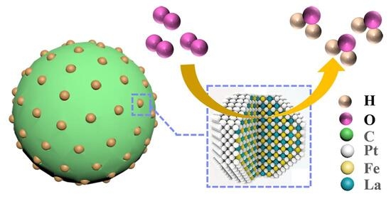
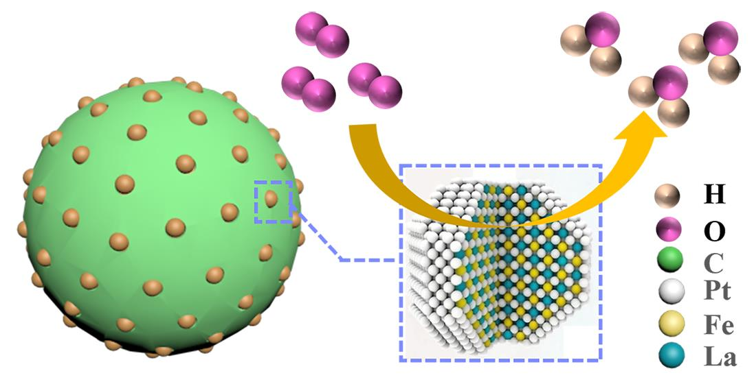
Graphical Abstract

1. Introduction

Proton exchange membrane fuel cells (PEMFCs) are expected to be a green and sustainable source of power in a future society due to their zero-emission operation [1,2]. However, the sluggish kinetics of the oxygen reduction reaction (ORR) at the cathode leads to a high overpotential, reducing PEMFC efficiency and necessitating highly active catalysts [3,4]. Furthermore, the harsh operating conditions (a strongly acidic and oxidative environment) at the cathode also require catalysts to possess high stability [5]. Therefore, developing highly durable and robust electrocatalysts remains a major obstacle for PEMFC application [6,7,8]. Platinum–transition metal alloy nanomaterials, particularly those alloying with Ni or Co, have been intensively researched for decades due to their promising ORR activity [4,9,10,11]. In Pt–transition metal alloys, the coupling between the 3d orbitals of the transition metals and the 5d orbitals of Pt modifies key parameters, including Pt’s 5d band vacancies, Pt-Pt atomic spacing, and Pt coordination number [12]. These modifications collectively cause a downward shift in the d-band center of Pt atoms away from the Fermi level [4,13]. Consequently, the electronic structure of Pt is altered, weakening the binding energy between Pt atoms and oxygen-containing species [10,14,15,16]. In contrast to the disordered atomic arrangement in solid–solution alloys, Pt-based intermetallic compounds with well-defined ordered structures, which generally include directed covalent bonds between ordered atoms, preventing the oxidation and dissolution of the transition metal under harsh acidic conditions and high potential, typically exhibit superior catalytic activity and long-term durability [7,17]. For example, Wang et al. [18] reported the ordered Pt3Co catalyst exhibited an over 200% increase in mass activity towards ORR compared with the disordered Pt3Co alloy and an excellent stability with minimal loss of activity after 5000 potential cycles.
In the past decade, a new kind of Pt-based alloy, Pt–rare earth metal alloys (Pt-RE alloys), has also been explored as an ORR catalyst [19,20,21,22]. For example, Hu et al. [23,24] prepared a series of Pt-RE nanoalloys (Pt3Y, Pt5La, Pt5Ce, Pt2Sm, Pt2Gd, and Pt3Tb) through the in situ-formed g-C3N4 network structure to stabilize rare earth metal atoms, and among them, Pt2Gd alloy exhibited the best ORR catalytic activity with a specific activity of 3.9 mA cm−2, which is 5.3 times higher than that of commercial Pt/C. Theoretical and experimental studies reveal that the ORR activity enhancement of Pt-RE alloys should originate from the formation of a compressively strained Pt overlayer [25]. Furthermore, given the exceptionally negative alloy formation energies and the formation of a protective Pt overlayer in acidic media, Pt-RE alloys present very stable alloy structures in acidic conditions [17,26,27]. Inspired by these developments, the introduction of rare earth metal atoms into intermetallic compounds might be an efficient strategy to delay the dissolution of transition metals and further tune the electronic structure of Pt atoms, thereby leading to improved activity and stability of intermetallic compounds in the acid environment of a fuel cell [28]. For example, Li et al. [29] incorporated La into the L12-Pt3Co intermetallic compound with a quasi-covalent Pt-M interaction, enhancing ORR activity and durability. Therefore, further exploration of incorporating rare earth metals into other kinds of ordered Pt–transition metal nanoalloys is highly worthwhile.
In this work, we demonstrate a novel L10-type intermetallic compound (L10-PtFe0.5La0.5@C) with the partial substitution of Fe sites with the rare earth metal of La. The as-prepared L10-PtFe0.5La0.5@C sample maintains ordered features after La incorporation. The obtained L10-PtFe0.5La0.5@C catalyst exhibits excellent ORR catalytic activity with a half-wave potential of 933 mV and a mass activity and specific activity of 1.28 and 1.32 times higher than those of the L10-PtFe@C catalyst, respectively. In addition, it also delivers a very stable performance in mass activity retention (0.70 A mgPt−1) after 20k cycles of accelerated durability tests.

2. Results and Discussion

2.1. Synthesis and Characterization of L10-PtFe0.5La0.5@C Catalyst

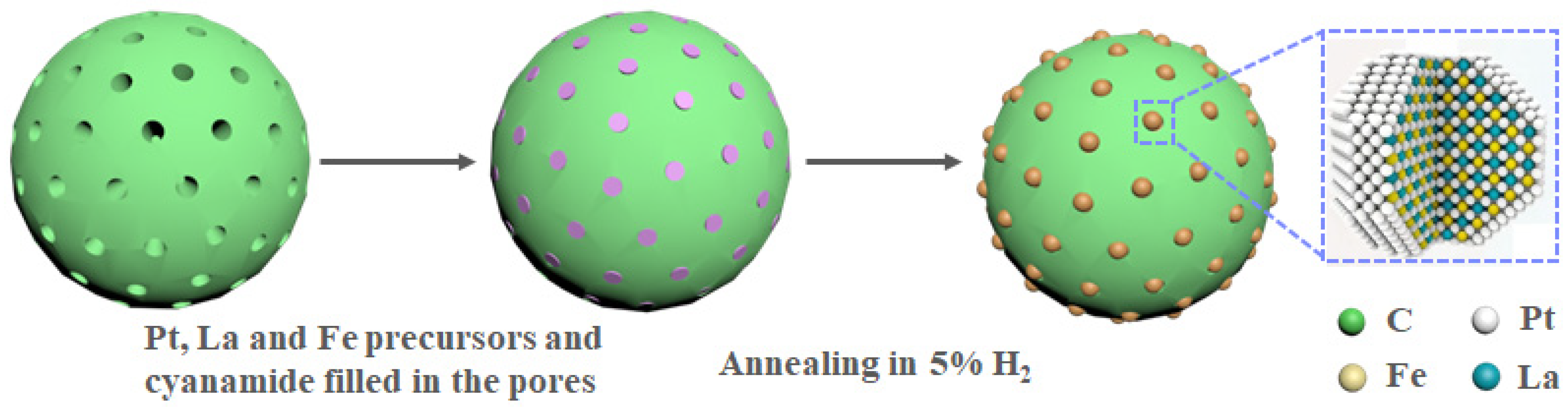
As shown in Figure 1, a sonication assistant incipient wetness impregnation method including the thermal reduction process was employed to synthesize La-incorporated L10-PtFe nanoalloys embedded in porous carbon (L10-PtFe0.5La0.5@C) [30,31]. Typically, a certain amount of H2PtCl6·6H2O, Fe(NO3)2·9H2O, La(NO3)3·6H2O and cyanamide was impregnated in Ketjenblack EC 600JD (KB600) and then annealed in a H2-Ar atmosphere (5% H2) with a program of 700 °C for 2 h and 900 °C for 2 h, and subsequently cooled down to 600 °C with a ramp rate of 1 °C min−1 to obtain the L10-PtFe0.5La0.5@C sample. The surface pores with a pore size of 3–5 nm in KB600 act as the nanoreactor and can restrict the growth and aggregation of PtFe0.5La0.5@C nanoparticles under high temperature which is reported in our previous works [32,33]. In addition, the high-temperature annealing and slow-rate cooling to 600 °C processes are beneficial to the formation of ordered structure [34]. As comparisons, the PtFe@C and PtFe0.5@C samples were also prepared by the same method without adding La(NO3)3·6H2O or the different ratios of Pt and Fe precursors, respectively. The Pt weight percentages for the L10-PtFe0.5La0.5@C, PtFe@C and PtFe0.5@C samples were 15.37 wt%, 15.19 wt% and 16.37 wt%, respectively, determined by inductively coupled plasma–optical emission spectroscopy (ICP-OES) (Tables S1–S3) and the molar ratios of Pt, Fe and La are consistent with their feeding ratios.
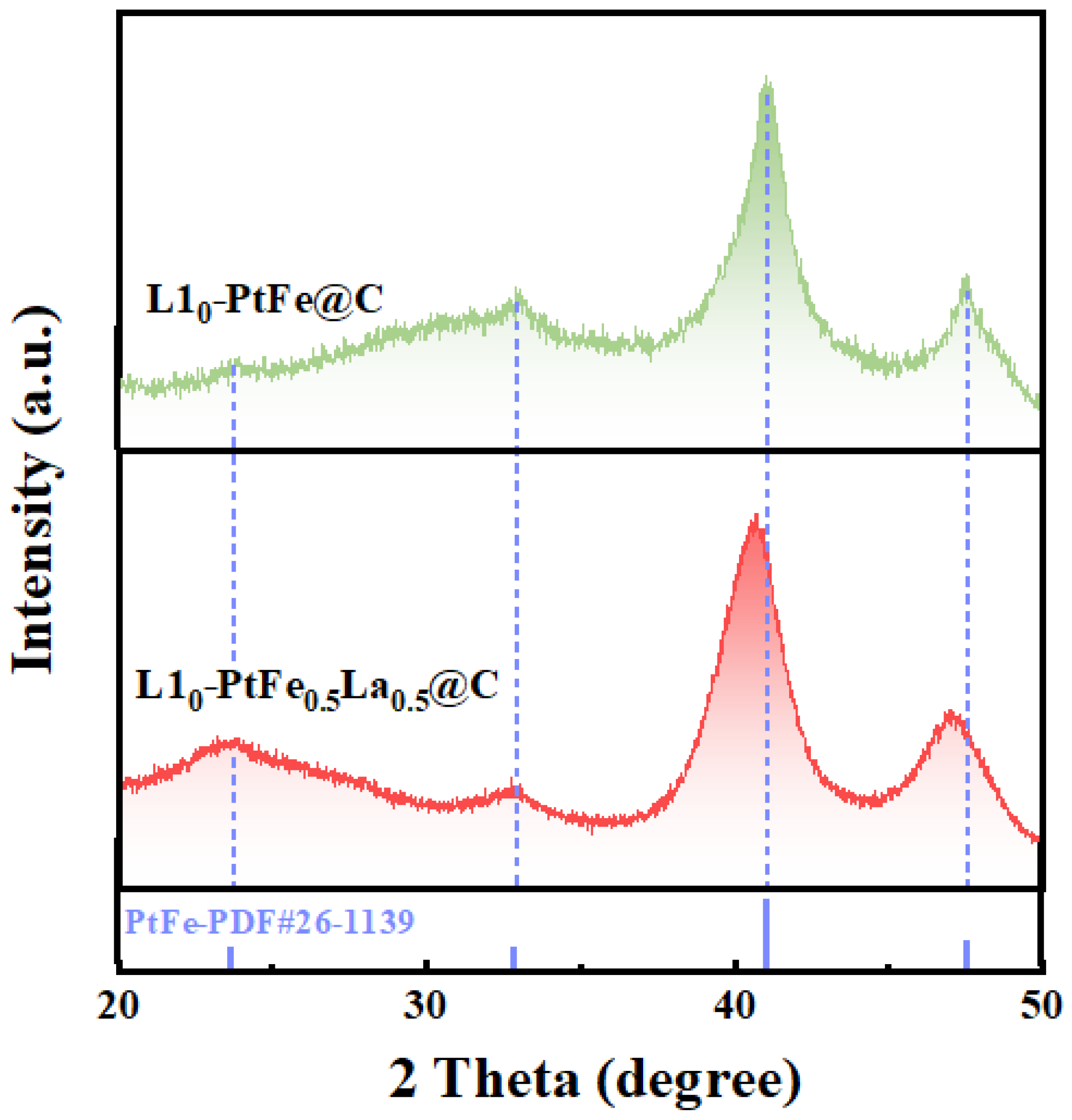
X-ray diffraction (XRD) analysis was firstly conducted to confirm the ordered structure of PtFe0.5La0.5 nanoparticles in the L10-PtFe0.5La0.5@C sample. Figure 2 shows the X-ray diffraction (XRD) patterns of L10-PtFe0.5La0.5@C sample with the L10-PtFe@C sample as a comparison. The superlattice-related peaks located at 24.1° and 33.0°, corresponding to the (001) and (100) facets of L10-PtFe (PDF card No. 26-1139), respectively, were observed in XRD patterns for the both L10-PtFe0.5La0.5@C and L10-PtFe@C samples, indicating the maintenance of an ordered structure after La substitution [35]. In addition, a broader peak around 24° can be assigned to the (002) plane of carbon which is overlapped with the superlattice peak. Moreover, it can be clearly observed that the peak around 41.1° corresponding to the (111) facet of L10-PtFe in the L10-PtFe0.5La0.5@C sample shifted to a lower angel compared to the pure L10-PtFe@C sample. That may be associated with the larger atomic radius of La compared to Fe and this result suggests the success of La substitution in Fe sites [36]. In addition, the broader diffraction peaks of the L10-PtFe0.5La0.5@C sample, such as the peak associated with the (111) facet, compared to the L10-PtFe@C sample, may reveal the smaller particle size or crystal distortion after La substitution [37]. The crystallite sizes for these samples calculated by the Scherrer equation based on the (111) facet-associated peaks were listed in Table S4, indicating the smaller particle size of the L10-PtFe0.5La0.5@C sample compared to the L10-PtFe@C and PtFe0.5@C samples. In addition, as shown in Figure S1, the PtFe0.5@C showed typical diffraction peaks associated with PtFe alloys with diffraction peaks shifting to a high degree compared to pure Pt [38], which further confirms the incorporation of La into the L10-PtFe lattice for the L10-PtFe0.5La0.5@C sample. In addition, although the L10-PtFe0.5La0.5@C sample still presented the characteristic features of an L10-type ordered structure after the incorporation of La, we need to point out that its ordering degree may be different to the L10-PtFe@C sample. Therefore, the tuning of ordering degree of this kind of rare earth metal-incorporated Pt–transition metal ordered nanoalloy needs to receive more attention in the future.
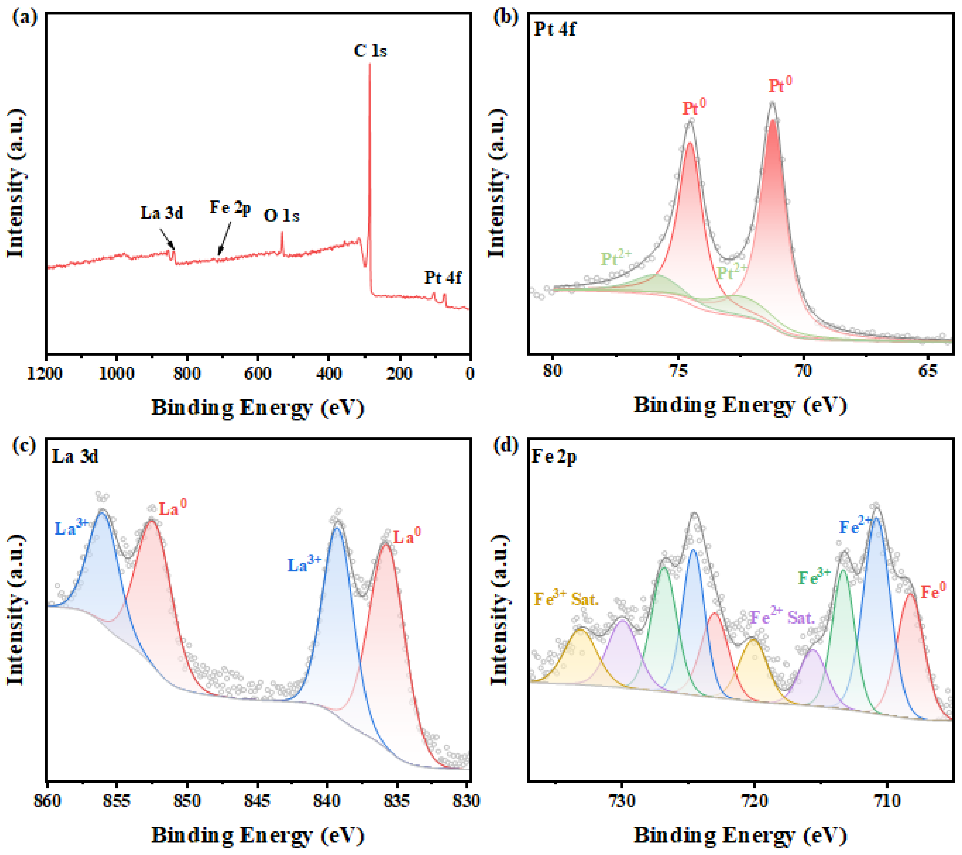
The chemical state of L10-PtFe0.5La0.5 nanoparticles in the L10-PtFe0.5La0.5@C sample was further analyzed using X-ray photoelectron spectroscopy (XPS). As shown in Figure 3a and Figure S2, the XPS survey spectrum shows that the L10-PtFe0.5La0.5@C possessed the characteristic Pt, Fe, La and C peaks. Figure 3b and Table S5 show that the Pt0 4f binding energies of L10-PtFe0.5La0.5@C (71.2/74.5 eV) have a negative shift compared to L10-PtFe@C (71.4/74.7 eV) (Figure S3) and PtFe0.5@C (71.5/74.8 eV) (Figure S4), indicating that more electrons were transferred to Pt [39]. Considering that the electronegativity of La (1.1) [40] is smaller than that of Fe (1.83) [41] and Pt (2.28) [40], the extra electrons transferred to Pt may be contributed by La, and that also indicates that La was successfully embedded in the PtFe lattice. Moreover, the appearance of the La0 3d signal also suggests the existence of La incorporation into the L10-PtFe0.5La0.5@C sample (Figure 3c). By the way, compared to L10-PtFe@C and PtFe0.5@C samples, the higher portion of Pt0 observed in the L10-PtFe0.5La0.5@C sample may predict better ORR activity [42]. In addition, the existence of La3+ [43], Fe2+ and Fe3+ species [44] in L10-PtFe0.5La0.5@C, L10-PtFe@C and PtFe0.5@C samples may be caused by the surface oxidation in the atmosphere [45]. In addition, the surface composition of L10-PtFe0.5La0.5@C, L10-PtFe@C and PtFe0.5@C samples measured by XPS is shown as Table S6. The similar surface compositions observed compared to bulk compositions (ICP results) may be associated with the L1-type ordered structure.
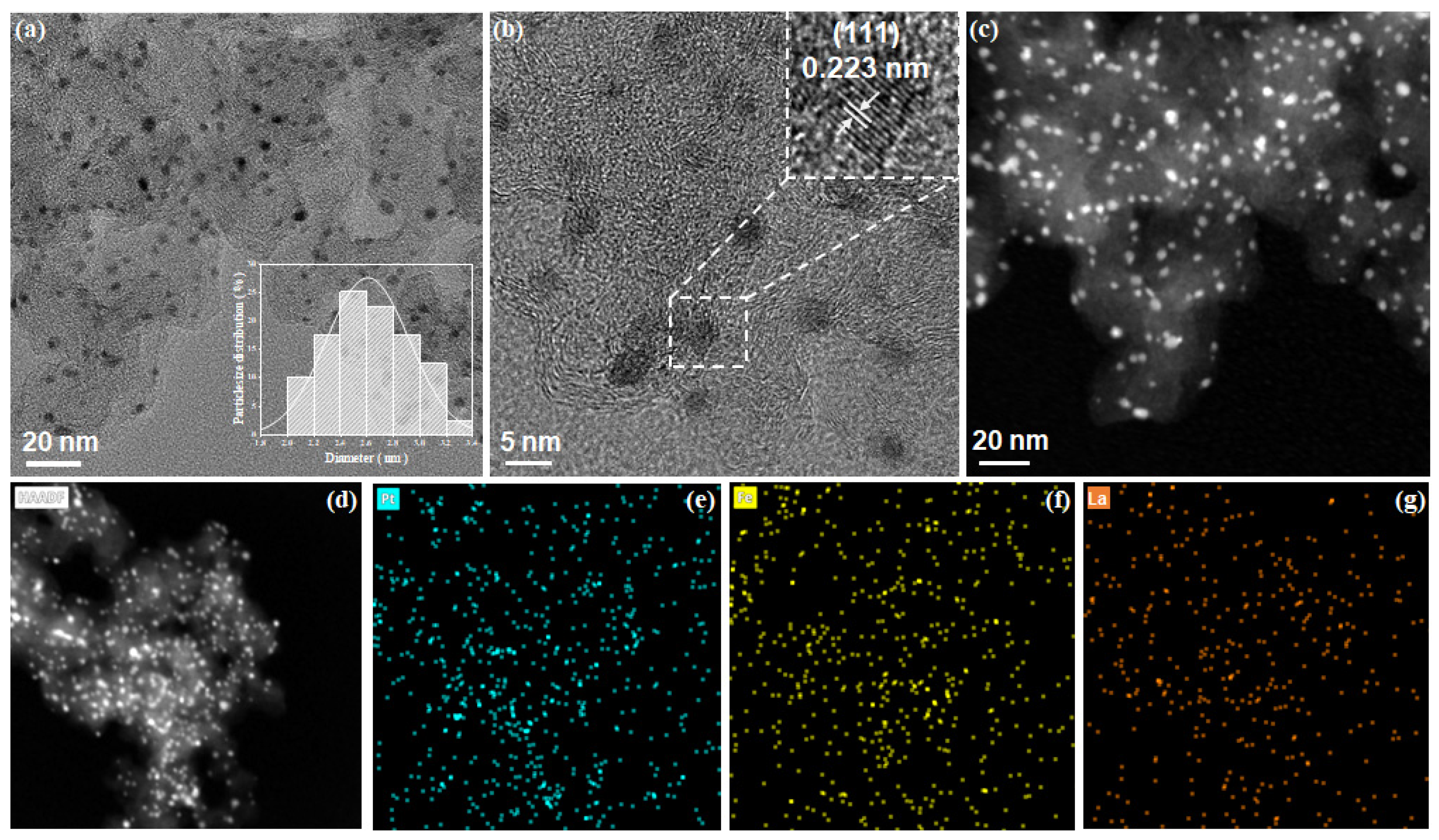
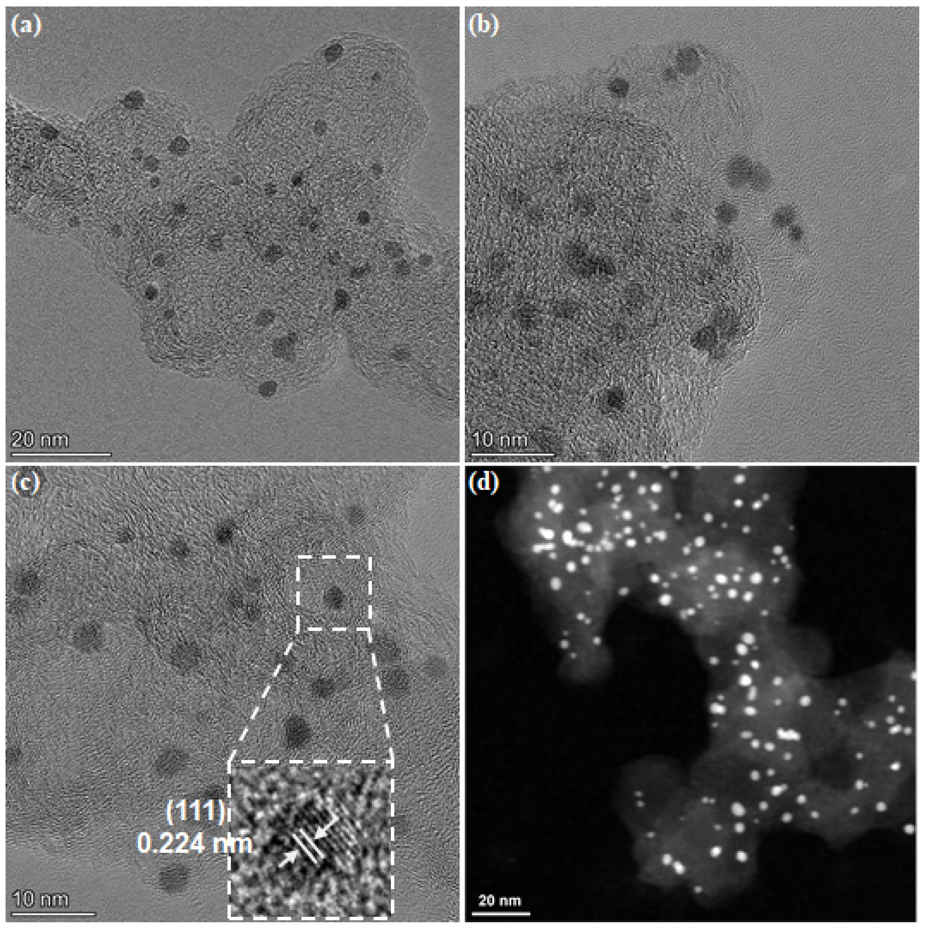
Transmission electron microscopy (TEM) and high-angle annular dark field scanning electron microscopy (HAADF-STEM) techniques was then used to analyze the morphology of the L10-PtFe0.5La0.5@C sample (Figure 4). The TEM (Figure 4a,b) and HAADF-STEM (Figure 4c) images show that the as-synthesized L10-tFe0.5La0.5@C displayed uniformly distributed nanoparticles embedded in porous carbon with the average nanoparticle size of around 2–3 nm. In addition, L10-PtFe@C and PtFe0.5@C samples showed similar morphologies (Figures S5–S8). Moreover, as shown in Figure 4b and Figure S9, the interplanar spacing of 0.223 nm was observed in the high-resolution TEM (HRTEM) image of the L10-PtFe0.5La0.5@C sample, which may be indexed to the (111) planes of L10-PtFe. It needs to be pointed out that this value is a little bigger than that of the L10-PtFe@C sample (Figures S7b and S8) which shows the standard value (0.220 nm for (111) facet). That result is in consistent with the XRD results which further confirms the La incorporation into the PtFe lattice [28]. Furthermore, elemental mapping based on the corresponding HAADF image (Figure 4d–g) demonstrates the homogeneous distribution of Pt, Fe, and La, indicating the uniform formation of La-incorporated PtFe nanoparticles into the L10-PtFe0.5La0.5@C catalyst. In addition, surface compositions of these four samples from EDS elemental mapping are summarized as Table S7 and are similar to the results obtained by XPS.

2.2. ORR Performance of L10-PtFe0.5La0.5@C Catalyst

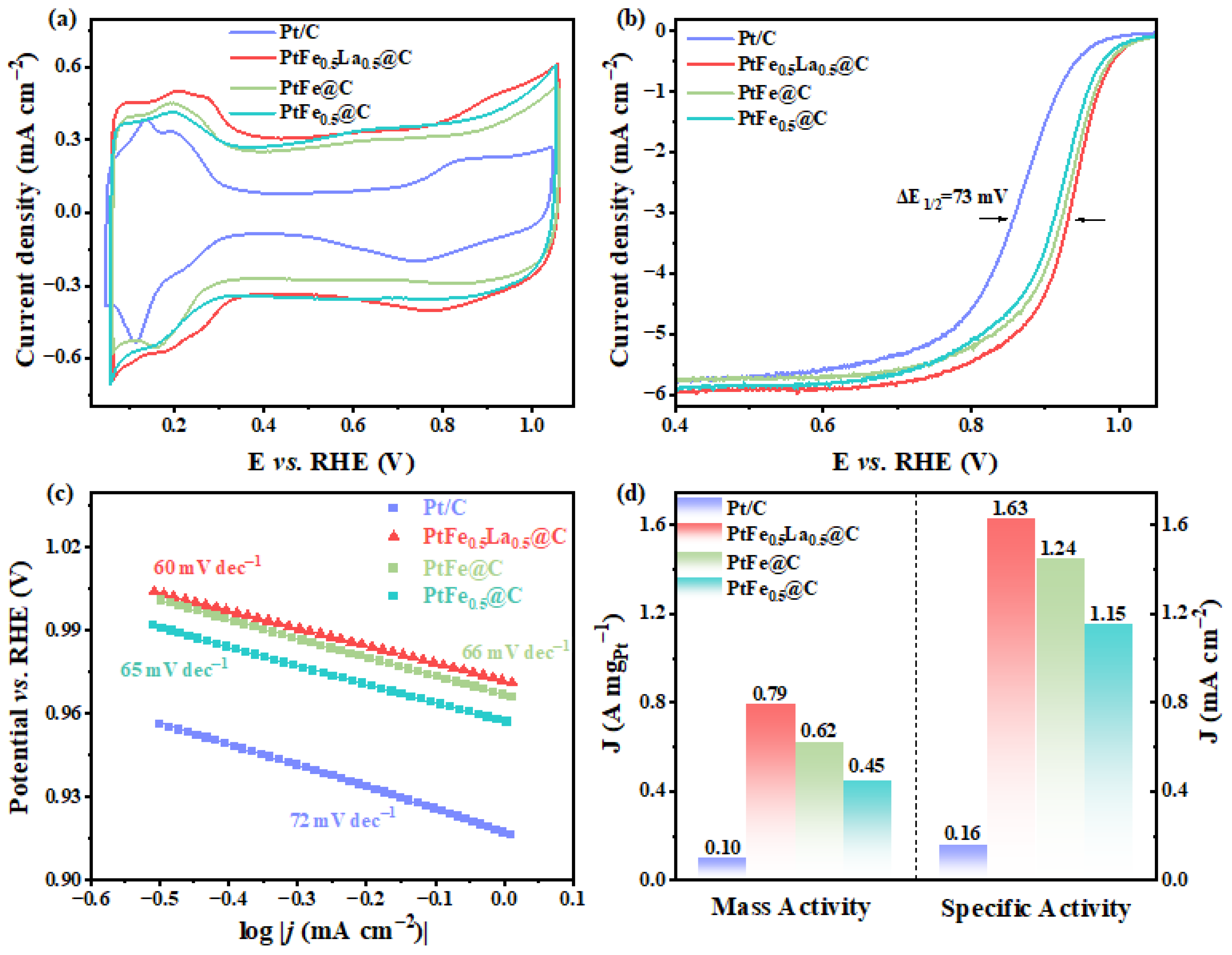
To investigate the ORR performance of the L10-PtFe0.5La0.5@C catalyst, the cyclic voltammogram (CV) curve was firstly recorded in Ar-saturated 0.1 M HClO4 solution with a scan rate of 20 mV s−1. The CV curves of L10-PtFe@C, PtFe0.5@C and commercial Pt/C catalysts were also tested as references. As shown in Figure 5a, a higher peak potential associated with the surface oxide reduction of Pt for L10-PtFe0.5La0.5@C was observed, relative to that of L10-PtFe@C, disordered PtFe0.5@C and commercial Pt/C, demonstrating the weakened Pt-OHads interaction, which suggests an improved ORR kinetics over the L10-PtFe0.5La0.5 surface [33]. And then, the electrochemical surface area (ECSA) can be further calculated through the hydrogen desorption peak area in the CV curves, and the L10-PtFe0.5La0.5@C sample showed an ECSA of 48.3 m2 gPt−1, which is a little higher than those of L10-PtFe@C (42.5 m2 gPt−1) and PtFe0.5@C (39.7 m2 gPt−1) catalysts (Table S8). In addition, these values are a little lower than that of Pt/C (65.0 m2 gPt−1) which may be associated with the alloying of transition metals which suppresses H adsorption [46]. Considering the Hupd-based ECSA is usually underestimated due to H adsorption suppression on multimetallic surfaces, the ECSAs of these samples were also determined by the CO stripping method (Figure S10) and the L10-PtFe0.5La0.5@C sample displayed a comparable value with Pt/C which may be related to the similar particle size (Table S4). In addition, the L10-PtFe0.5La0.5@C sample showed the lowest CO oxidation peak potential (826 mV) among these samples, suggesting its good capability for CO tolerance [47].
The ORR polarization curve of the L10-PtFe0.5La0.5@C catalyst was then measured in an O2-saturated 0.1 M HClO4 solution with a scan rate of 10 mV s−1 under the electrode rotation of 1600 rpm. As shown in Figure 5b, the half-wave potential (E1/2) of the L10-PtFe0.5La0.5@C catalyst was about 933 mV, which is much more positive than that of L10-PtFe@C (921 mV) and PtFe0.5@C (913 mV) and also 73 mV higher than that of the commercial Pt/C catalyst under the same condition. Figure 5c shows the Tafel slopes of the L10-PtFe0.5La0.5@C catalyst at the high-potential region from 1.0 to 0.9 V with the comparisons of L10-PtFe@C, PtFe0.5@C and commercial Pt/C catalysts. The Tafel slope of the L10-PtFe0.5La0.5@C catalyst was fitted as 60 mV dec−1, very close to L10-PtFe@C (66 mV dec−1), PtFe0.5@C (65 mV dec−1) and the commercial Pt/C catalyst (72 mV dec−1), which reveals a similar ORR pathway and rate-determined step over their Pt sites [48]. Furthermore, a slightly lower Tafel slope for the L10-PtFe0.5La0.5@C sample, compared to the rest of the samples, may indicate its enhanced reaction kinetics towards ORR. The kinetic mass activity (MA) and specific activity (SA) were also calculated by normalizing the kinetic current densities of catalysts at 0.9 V vs. RHE to the Pt loading and ECSA, respectively, with the Koutecky–Levich equation. As shown in Figure 5d and Table S8, the L10-PtFe0.5La0.5@C catalyst demonstrated a mass activity of 0.79 A mgPt−1, which outperforms the L10-PtFe@C (0.62 A mgPt−1) and the disordered PtFe0.5@C (0.45 A mgPt−1) samples, and reveals nearly eight-fold improvement over the commercial Pt/C catalyst (0.10 A mgPt−1). Moreover, the specific activity of PtFe0.5La0.5@C was 1.63 mA cm−2, which is also higher than those for L10-PtFe@C (1.24 mA cm−2), disordered PtFe0.5@C (1.15 mA cm−2) and commercial Pt/C (0.16 mA cm−2) catalysts. These findings reveal that the substitution of Fe sites by La atoms in PtFe may effectively induce the formation of a strained Pt overlayer, which adjusts the adsorption ability of the surface Pt site to oxygen-containing intermediates, thus enhancing the ORR performance of L10-PtFe0.5La0.5@C [20].
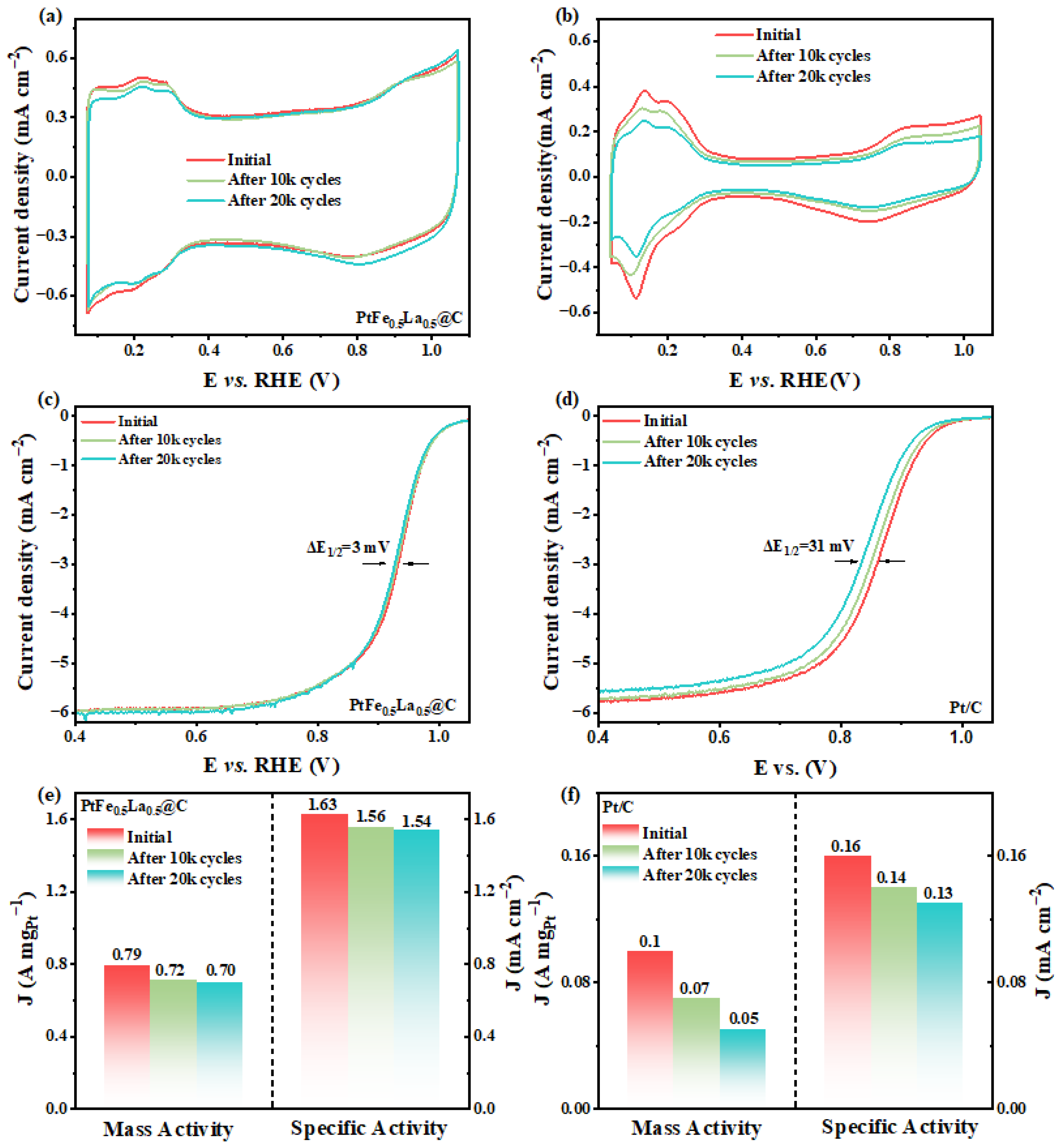
Additionally, the durability of the catalysts was also evaluated through an accelerated stability test (ADT) by the potential cycling between 0.6 and 1.0 V for up to 20k cycles in air-saturated 0.1 M HClO4 solution. Figure 6a shows the CV curves of L10-PtFe0.5La0.5@C before and after 20k CV cycles of ADT and the change in the ECSA of the L10-PtFe0.5La0.5@C sample was only 6.4% after 20k potential cycles, which is significantly smaller than that of 36.1% for the commercial Pt/C catalyst (Figure 6b), suggesting the excellent retention of Pt active sites for the L10-PtFe0.5La0.5@C sample. After 20k cycles of ADT, the half-wave potential of L10-PtFe0.5La0.5@C was lost by only 3 mV (Figure 6c), while commercial Pt/C experienced 31 mV degradation (Figure 6d). Moreover, the MA of PtFe0.5La0.5@C is 88.6% maintained, demonstrating remarkable stability (Figure 6e). In comparison, the mass activity of the Pt/C was lost by about 50%. The structural stability of the L10-PtFe0.5La0.5@C catalyst after 20k of potential cycles was further examined by microscopic imaging. Figure 7 and Figure S11 present typical TEM and HAADF-STEM images of the L10-PtFe0.5La0.5@C catalyst at various magnifications after the ADT. The images show minimal change in particle size, revealing high resistance to agglomeration and sintering which may be related to the features of the embedded structure [33]. Furthermore, the negligible change in lattice spacing (Figure 7c) indicates excellent structural integrity of L10-PtFe0.5La0.5 nanoparticles, pointing to robust resistance to the dissolution of Fe and La in acidic environments, ensuring long-term stability, which is in agreement with its electrochemical results above. In addition, a slight decrease in Fe/La contents against Pt after ADT may be associated with the surface decomposition of Fe/La and the formation of Pt layers during this process. That superior durability may be due to the La occupation in the PtFe generating a strong bonding characteristic and a protective Pt overlayer which is similar to Pt-RE alloys [39].

3. Experimental Section

3.1. Chemicals

Lanthanum nitrate hexahydrate (La(NO3)3·6H2O, 99.9%), iron nitrate nonahydrate (Fe(NO3)3·9H2O, 99.99%) and anhydrous ethanol were bought from Titan Technology Co., Ltd. (Shanghai, China). 2-Propanol, cyanamide, perchloric acid (70%) and chloroplatinic acid hexahydrate (H2PtCl6·6H2O, 37.50% Pt basis) were purchased from Sigma-Aldrich (Saint Louis, MO, USA). Ketjenblack EC-600JD was purchased from Akzo Nobel (Amsterdam, The Netherlands). Commercial Pt/C (46.6 wt% Pt, Pt particle size: 2.6 nm) was purchased from Tanaka Kikinzoku International Inc. (Tokyo, Japan) All chemicals were used as received without further purification.

3.2. Synthesis of La-Incorporated L10-PtFe Intermetallic Compound (L10-PtFe0.5La0.5@C)

La-incorporated L10-PtFe intermetallic compound (L10-PtFe0.5La0.5@C) was synthesized by a method combining the wetness impregnation and thermal annealing processes. Typically, the anhydrous ethanol solution containing 50 umol H2PtCl6·6H2O, 25 umol Fe(NO3)3·9H2O, 25 umol La(NO3)3·6H2O and 80 mg cyanamide was added into a vial with 50 mg Ketjenblack EC-600JD and further sonicated for 2 h. After drying at 70 °C for 12 h, 300 mg cyanamide was further added through the same method as above. And then, the dried powder was transferred into a tube furnace for further annealing under a 5% H2/95% Ar atmosphere at 700 °C for 2 h and 900 °C for 2 h (ramp rate: 10 °C/min), and subsequently cooled down to 600 °C with a ramp rate of 1 °C min−1, followed with cooling naturally to room temperature to obtain the L10-PtFe0.5La0.5@C catalyst. As comparisons, L10-PtFe@C and disordered PtFe0.5@C were also prepared by the same method except for the absence of La(NO3)3·6H2O or the different ratios of Pt and Fe precursors.

3.3. Physical Characterizations

X-ray diffraction (XRD) measurement was conducted on an X-ray diffractometer (Rigaku, SmartLab-9 kW) (Tokyo, Japan,) under Cu Kα radiation (λ = 0.15406 nm) at a scan rate of 3° min−1. Transmission electron microscopy (TEM), high-resolution transmission electron microscopy (HRTEM) and high-angle annular dark field scanning transmission electron microscopy (HADDF-STEM) were performed using the Thermo Fisher Talos F200X G2 (Waltham, MA, USA). The chemical composition of catalysts was determined by inductively coupled plasma atomic emission spectroscopy (710-ES, Varian, ICP-OES) (Palo Alto, CA, USA). X-ray photoelectron spectroscopy (XPS) investigations were carried out using a Thermo Scientific K-Alpha XPS spectrometer (Wilmington, DE, USA).

3.4. Electrochemical Measurements

The electrochemical measurements were conducted on a CHI 760E electrochemical workstation (Shanghai CH Instruments) (Shanghai, China) using a three-electrode test cell. The working electrode is a glassy carbon electrode (GCE) (d = 5 mm, the geometric electrode area is 0.196 cm2) coating with catalyst ink, while Pt foil and Ag/AgCl electrode (with saturated KCl solution) served as the counter electrode and reference electrode, respectively. For the electrolyte, 0.1 M HClO4 solution was used. The test potentials (vs. Ag/AgCl) were all converted to the reversible hydrogen electrode potential scale according to the equation (ERHE = EAg/AgCl + Ecalibration). The Ag/AgCl electrode was calibrated by testing the open circuit potential against a reversible hydrogen electrode (Figure S12) for every use. The catalyst ink was prepared by dissolving a certain amount of catalyst into the mixture of ultrapure water/iso-propanol (v/v = 3:1) containing 5 wt% Nafion (the solvent and Nafion volume ratio was controlled as 97:3) and sonicating for 30 min in an ice bath. The working electrode was obtained by dropping 20 μL catalyst ink onto the GCE and drying at room temperature. The catalyst loading was controlled at 20 μgPt cm−2. Cyclic voltammetry (CV) measurements were firstly conducted in Ar-saturated 0.1 M HClO4 solution between 0.05 V and 1.05 V with a scan rate of 50 mV s−1 until a stable CV curve was obtained. After the catalyst was activated, the CV curve was measured from 0.05 V to 1.05 V with a scan rate of 20 mV s−1 in Ar-saturated 0.1 M HClO4 solution. The ECSA was determined by integrating the hydrogen underpotential deposition area (Hupd) in the CV curve by taking a value of 210 μC cm−2 for the adsorption of one monolayer of hydrogen. In addition, the ECSA of the catalyst was also determined by conducting CO stripping voltammetry. The working electrode was held at 0.05 V while purging CO through the electrolyte followed by saturating with Ar. The ECSA was calculated from the CO oxidation charge recorded at a scan rate of 50 mV s−1 using a conversion coefficient of 390 μC cm−2. The ORR polarization curve was collected in an O2-saturated 0.1 M HClO4 solution with a scan rate of 10 mV s−1 with the electrode rotation rate of 1600 rpm. The kinetic current (Ik) can be calculated using the Koutecky–Levich equation which is expressed by 1 I = 1 I k + 1 I d , where I is the measured current and Id is the diffusion limited current. The stability of catalyst was investigated in air-saturated 0.1 M HClO4 solution by accelerated durability testing (ADT) with CV cycling between 0.6 V and 1.0 V with a scan rate of 50 mV s−1 up to 20k cycles.

4. Conclusions

In summary, a rare earth metal, La, was introduced to partially substitute the Fe sites of L10 PtFe ordered nanoalloy and formed a novel L10-type intermetallic nanoalloy (L10-PtFe0.5La0.5@C) keeping the ordered structure features after La incorporation. The L10-PtFe0.5La0.5@C sample with a particle size around 2–3 nm embedded in porous carbon showed an excellent ORR performance with the half-wave potential of 933 mV, an intrinsic specific activity of 1.63 mA cm−2 and a mass activity of 0.79 A mgPt−1 at 0.90 V in acidic media (0.1 M HClO4 electrolyte). All these key metrics exceeded those of the L10-PtFe@C and commercial Pt/C catalysts. Moreover, it also exhibited very stable ORR activity after 20k CV cycles ADT. The strong bonding character and the formation of a strained, protective Pt overlayer after La incorporation may be the reasons for its enhanced activity and durability. In addition, this study also expands the scope of intermetallic compounds and provides a new direction to develop Pt-based intermetallic catalysts.

Supplementary Materials

The following supporting information can be downloaded at https://www.mdpi.com/article/10.3390/catal16050373/s1: Figure S1. XRD patterns of L10-PtFe@C and PtFe0.5@C samples; Figure S2. C 1s XPS spectrum of L10-PtFe0.5La0.5@C sample; Figure S3. (a) XPS survey, (b) C 1s, (c) Pt 4f, and (d) Fe 2p XPS spectra of L10-PtFe@C sample; Figure S4. (a) XPS survey, (b) C 1s, (c) Pt 4f, and (d) Fe 2p XPS spectra of PtFe0.5@C sample; Figure S5. (a) TEM (insertion is the particle size distribution of PtFe0.5 nanoparticles), (b) HR-TEM, (c) HAADF-STEM images, and (d) HAADF-STEM and corresponding EDS elemental mapping images, (e) Pt, and (f) Fe of the PtFe0.5@C catalyst; Figure S6. The analysis of d-spacing for PtFe0.5 nanoparticles via HRTEMv Figure S7. (a) TEM (insertion is particle size distribution of PtFe nanoparticles), (b) HR-TEM, (c) HAADF-STEM image, and (d) HAADF-STEM and corresponding EDS elemental mapping images, (e) Pt, and (f) Fe of the L10-PtFe@C catalyst; Figure S8. The analysis of d-spacing for L10-PtFe nanoparticles via HRTEM; Figure S9. The analysis of d-spacing for L10-PtFe0.5La0.5 nanoparticles via HRTEM; Figure S10. CO-stripping curves of L10-PtFe0.5La0.5@C, L10-PtFe@C, PtFe0.5@C and Pt/C; Figure S11. The analysis of d-spacing for PtFe0.5La0.5 nanoparticles after ADT via HRTEM; Figure S12. The calibration curve of Ag/AgCl electrode in 0.1 M HClO4 solution against reversible hydrogen electrode; Table S1. Chemical composition of L10-PtFe0.5La0.5@C sample determined by ICP-OES; Table S2. Chemical composition of PtFe@C sample determined by ICP-OES; Table S3. Chemical composition of PtFe0.5@C sample determined by ICP-OES; Table S4. The crystallite sizes calculated by the Scherrer equation; Table S5 Binding energy and atomic ratios of Pt spices in L10-PtFe0.5La0.5@C, L10-PtF@C and PtFe0.5@C samples; Table S6. Composition of L10-PtFe0.5La0.5@C, L10-PtFe@C and PtFe0.5@C samples measured by XPS; Table S7. Compositions of L10-PtFe0.5La0.5@C, L10-PtFe@C and PtFe0.5@C samples measured by EDS; Table S8. Comparisons of ORR performance of L10-PtFe0.5La0.5@C, L10-PtFe@C, PtFe0.5@C and commercial Pt/C catalysts.

Author Contributions

Investigation, Data curation, Writing—original draft—C.Y. Investigation, Data curation—J.Z. Investigation, Data curation—S.W. Data curation—J.L. Investigation, Writing—review and editing—L.L. Data curation—J.J. Data curation—R.C. Data curation—W.B. Data curation—X.C. Methodology, Project administration, Funding acquisition, Supervision, Writing—review and editing—Z.M. All authors have read and agreed to the published version of the manuscript.

Funding

This research was funded by the National Natural Science Foundation of China (22208214).

Data Availability Statement

Data are contained within the article.

Conflicts of Interest

The authors declare no conflicts of interest.

References

  1. Jiao, K.; Xuan, J.; Du, Q.; Bao, Z.; Xie, B.; Wang, B.; Zhao, Y.; Fan, L.; Wang, H.; Hou, Z.; et al. Designing the next generation of proton-exchange membrane fuel cells. Nature 2021, 595, 361–369. [Google Scholar] [CrossRef]
  2. Musgrave, C.B., III; Su, J.; Xiong, P.; Song, Y.; Huang, L.; Liu, Y.; Li, G.; Zhang, Q.; Xin, Y.; Li, M.M.-J.; et al. Molecular strain accelerates electron transfer for enhanced oxygen reduction. J. Am. Chem. Soc. 2025, 147, 3786–3795. [Google Scholar] [CrossRef]
  3. Yang, G.; Lee, C.; Qiao, X.; Babu, S.K.; Martinez, U.; Spendelow, J.S. Advanced electrode structures for proton exchange membrane fuel cells: Current status and path forward. Electrochem. Energy Rev. 2024, 7, 9. [Google Scholar] [CrossRef]
  4. Ma, Z.; Cano, Z.P.; Yu, A.; Chen, Z.; Jiang, G.; Fu, X.; Yang, L.; Wu, T.; Bai, Z.; Lu, J. Enhancing oxygen reduction activity of Pt-based electrocatalysts: From theoretical mechanisms to practical methods. Angew. Chem. Int. Ed. 2020, 59, 18334–18348. [Google Scholar] [CrossRef] [PubMed]
  5. Zhang, J.; Yuan, Y.; Gao, L.; Zeng, G.; Li, M.; Huang, H. Stabilizing Pt-based electrocatalysts for oxygen reduction reaction: Fundamental understanding and design strategies. Adv. Mater. 2021, 33, 2006494. [Google Scholar] [CrossRef] [PubMed]
  6. Ye, W.; Wu, Z.; Zhang, S.; Sun, Y.; Zhang, X.; Zhou, W.; Cao, W.; Wang, T.; Cheng, D.; Xie, H. PtNi alloy nanoparticles grown in situ on nitrogen doped carbon for the efficient oxygen reduction reaction. Dalton Trans. 2023, 52, 10817–10827. [Google Scholar] [CrossRef]
  7. Zhang, L.; Deng, Y.; Zhang, J.; Tan, W.; Wang, L.; Du, L.; Song, H.; Liao, S.; Dang, D.; Sun, S.; et al. Optimized surface strain in L10-type Pt0.8Ga0.2Co intermetallic catalyst for enhanced oxygen reduction in fuel cells. Chem. Mater. 2024, 36, 11404–11411. [Google Scholar] [CrossRef]
  8. Yuan, C.; Zhang, S.; Zhang, J. Oxygen reduction electrocatalysis: From conventional to single-atomic platinum-based catalysts for proton exchange membrane fuel cells. Front. Energy 2024, 18, 206–222. [Google Scholar] [CrossRef]
  9. Huang, L.; Zaman, S.; Tian, X.; Wang, Z.; Fang, W.; Xia, B.Y. Advanced platinum-based oxygen reduction electrocatalysts for fuel cells. Acc. Chem. Res. 2021, 54, 311–322. [Google Scholar] [CrossRef]
  10. Huang, J.; Sementa, L.; Liu, Z.; Barcaro, G.; Feng, M.; Liu, E.; Jiao, L.; Xu, M.; Leshchev, D.; Lee, S.-J.; et al. Experimental Sabatier plot for predictive design of active and stable Pt-alloy oxygen reduction reaction catalysts. Nat. Catal. 2022, 5, 513–523. [Google Scholar] [CrossRef]
  11. Yin, S.; Song, Y.; Liu, H.; Cui, J.; Liu, Z.; Li, Y.; Xue, T.; Tang, W.; Zhang, D.; Li, H.; et al. Well-defined PtCo@Pt core-shell nanodendrite electrocatalyst for highly durable oxygen reduction reaction. Small 2025, 21, 2410080. [Google Scholar] [CrossRef]
  12. Nie, Y.; Shi, Z.; Li, B.; Meyer, Q.; Zhao, C. Engineering platinum-based alloy catalysts for oxygen reduction reaction in hydrogen fuel cells: A mini-review. Energy Fuels 2025, 39, 16049–16064. [Google Scholar] [CrossRef]
  13. Alfaifi, S.M.; Balu, R.; Chiang, K.; Choudhury, N.R.; Dutta, N.K. Electrocatalysts for the oxygen reduction reaction in proton exchange membrane fuel cells: Significant advances, major challenges, and future directions. ACS Catal. 2025, 15, 9301–9345. [Google Scholar] [CrossRef]
  14. Jin, H.; Xu, Z.; Hu, Z.-Y.; Yin, Z.; Wang, Z.; Deng, Z.; Wei, P.; Feng, S.; Dong, S.; Liu, J.; et al. Mesoporous Pt@Pt-skin Pt3Ni core-shell framework nanowire electrocatalyst for efficient oxygen reduction. Nat. Commun. 2023, 14, 1518. [Google Scholar] [CrossRef]
  15. Chen, Y.; Jin, Z.; Sun, J.; Chen, S.; Zhang, J.; Zhang, S. Precise Pt-skin manipulation of strain and ligand effects for oxygen reduction. eScience 2025, 5, 100396. [Google Scholar] [CrossRef]
  16. Strasser, P.; Kühl, S. Dealloyed Pt-based core-shell oxygen reduction electrocatalysts. Nano Energy 2016, 29, 166–177. [Google Scholar] [CrossRef]
  17. Li, J.; Sharma, S.; Liu, X.; Pan, Y.-T.; Spendelow, J.S.; Chi, M.; Jia, Y.; Zhang, P.; Cullen, D.A.; Xi, Z.; et al. Hard-magnet L10-CoPt nanoparticles advance Fuel Cell catalysis. Joule 2019, 3, 124–135. [Google Scholar] [CrossRef]
  18. Wang, D.; Xin, H.L.; Hovden, R.; Wang, H.; Yu, Y.; Muller, D.A.; DiSalvo, F.J.; Abruña, H.D. Structurally ordered intermetallic platinum-cobalt core-shell nanoparticles with enhanced activity and stability as oxygen reduction electrocatalysts. Nat. Mater. 2013, 12, 81–87. [Google Scholar] [CrossRef] [PubMed]
  19. Cai, R.; Bi, W.; Liao, J.; Yang, S.; Yin, J.; Zhu, J.; Liu, X.; Liu, Y.; Ma, Z. Simple synthesis of ultrasmall Pt5La nanoalloy for highly efficient oxygen reduction reaction. Catalysts 2026, 16, 97. [Google Scholar] [CrossRef]
  20. Malacrida, P.; Escudero-Escribano, M.; Verdaguer-Casadevall, A.; Stephens, I.E.L.; Chorkendorff, I. Enhanced activity and stability of Pt-La and Pt-Ce alloys for oxygen electroreduction: The elucidation of the active surface phase. J. Mater. Chem. A 2014, 2, 4234–4243. [Google Scholar] [CrossRef]
  21. Peera, S.G.; Lee, T.G.; Sahu, A.K. Pt-rare earth metal alloy/metal oxide catalysts for oxygen reduction and alcohol oxidation reactions: An overview. Sustain. Energy Fuels 2019, 3, 1866–1891. [Google Scholar] [CrossRef]
  22. Dang, R.; Liang, H.; Huang, F.; Yin, F. Controllable gas-phase synthesis of Pt-Gd nanoalloy catalysts and electrocatalytic performance for oxygen reduction reaction. J. Alloys Compd. 2025, 1021, 179748. [Google Scholar] [CrossRef]
  23. Hu, Y.; Jensen, J.O.; Cleemann, L.N.; Brandes, B.A.; Li, Q. Synthesis of Pt-rare earth metal nanoalloys. J. Am. Chem. Soc. 2020, 142, 953–961. [Google Scholar] [CrossRef] [PubMed]
  24. Hu, Y.; Jensen, J.O.; Norby, P.; Cleemann, L.N.; Yang, F.; Li, Q. Mechanistic insights into the synthesis of platinum-rare earth metal nanoalloys by a solid-state chemical route. Chem. Mater. 2021, 33, 535–546. [Google Scholar] [CrossRef]
  25. Kanady, J.S.; Leidinger, P.; Haas, A.; Titlbach, S.; Schunk, S.; Schierle-Arndt, K.; Crumlin, E.J.; Wu, C.H.; Alivisatos, A.P. Synthesis of Pt3Y and other early-late intermetallic nanoparticles by way of a molten reducing agent. J. Am. Chem. Soc. 2017, 139, 5672–5675. [Google Scholar] [CrossRef]
  26. Hu, M.; Cai, Z.; Liang, X.; Li, G.; Tan, H.; Yang, S.; Ren, H.; Wang, Z.; Sun, G.; Liu, S.; et al. Surface-confined synthesis of ultrafine Pt-rare earth nanoalloys on N-functionalized supports. Adv. Funct. Mater. 2022, 32, 2202675. [Google Scholar] [CrossRef]
  27. Fan, C.; Wen, P.; Li, G.; Li, G.; Gu, J.; Li, Q.; Li, B. Facile synthesis of Pt5La nanoalloys as the enhanced electrocatalysts for oxygen reduction reaction and methanol oxidation reaction. J. Alloys Compd. 2022, 894, 161892. [Google Scholar] [CrossRef]
  28. Zhang, X.; Lin, X.; Hu, X.; Geng, S.; Xiao, F.; Jiang, K.; Li, S.; Zheng, Z.; Bu, L. General method for trimetallic platinum-cobalt-rare earth alloys on nitrogen-doped carbon as efficient methanol electrooxidation catalysts. ACS Catal. 2024, 14, 84–93. [Google Scholar] [CrossRef]
  29. Li, C.; Li, K.; Deng, G.; Yang, L.; Bai, J.; Han, X.; Jia, X.; Zhu, J.; Sun, H.; Liu, W.; et al. Lanthanum-induced quasi-covalent bonding and chemical potential bridging in Pt3Co intermetallic catalysts for durable fuel cells. J. Am. Chem. Soc. 2026, 148, 3174–3184. [Google Scholar] [CrossRef] [PubMed]
  30. Chong, Z.; Chen, Y.; Zhao, Y.; Yu, R.; Liao, J.; He, Y.; Luo, L.; Shen, S.; Gao, X.; Zuo, Z.; et al. Space-confined synthesis of highly dispersed platinum on Mo2C enables efficient acidic hydrogen evolution. Appl. Catal. B Environ. Energy 2026, 387, 126503. [Google Scholar] [CrossRef]
  31. Cai, R.; Jiang, J.; Diao, P.; Wei, Z.; Yao, C.; Zhou, B.; Zhang, H.; Liu, W.; Ma, Z. Highly dispersed ZIF-67-derived co-NC confined in carbon pores enables efficient oxygen reduction in alkaline media. J. Electroanal. Chem. 2025, 989, 119212. [Google Scholar] [CrossRef]
  32. Wei, Z.; Chong, Z.; Wang, S.; Chen, Y.; Cai, R.; Yao, C.; Ma, Z.; Li, G. Subsize Ru nanoparticles embedded in porous carbon with highly metallic surface enable efficient hydrogen evolution. Int. J. Hydrogen Energy 2025, 129, 10–19. [Google Scholar] [CrossRef]
  33. Ma, Z.; Li, S.; Wu, L.; Song, L.; Jiang, G.; Liang, Z.; Su, D.; Zhu, Y.; Adzic, R.R.; Wang, J.X.; et al. NbOx nano-nail with a Pt head embedded in carbon as a highly active and durable oxygen reduction catalyst. Nano Energy 2020, 69, 104455. [Google Scholar] [CrossRef]
  34. Zeng, W.-J.; Wang, C.; Yan, Q.-Q.; Yin, P.; Tong, L.; Liang, H.-W. Phase diagrams guide synthesis of highly ordered intermetallic electrocatalysts: Separating alloying and ordering stages. Nat. Commun. 2022, 13, 7654. [Google Scholar] [CrossRef]
  35. Wang, M.; Liu, Y.; Li, Y.; Chen, S.; Wei, Z. Stabilizing Fe in intermetallic L10-PtAuFe nanoparticles with strong Au-Fe bond to boost oxygen reduction reaction activity and durability. Chem. Eng. J. 2023, 465, 142748. [Google Scholar] [CrossRef]
  36. Itahara, H.; Takatani, Y.; Takahashi, N.; Kosaka, S.; Nagoya, A.; Inaba, M.; Kamitaka, Y.; Morimoto, Y. Synthesis of carbon-supported intermetallic Pt5Ce compound nanoparticles via a water-based impregnation route. Chem. Mater. 2022, 34, 422–429. [Google Scholar] [CrossRef]
  37. Liu, W.; Wang, A.; Zhang, J.; Yu, S.; Wang, M.; Tian, S.; Tang, H.; Zhao, Z.; Ren, X.; Guo, Y.; et al. Pt/α-MoC Catalyst Boosting pH-Universal Hydrogen Evolution Reaction at High Current Densities. ACS Nano 2025, 19, 10038–10047. [Google Scholar] [CrossRef] [PubMed]
  38. Luo, M.; Qin, Y.; Li, M.; Sun, Y.; Li, C.; Li, Y.; Yang, Y.; Lv, F.; Wu, D.; Zhou, P.; et al. Interface modulation of twinned PtFe nanoplates branched 3D architecture for oxygen reduction catalysis. Sci. Bull. 2020, 65, 97–104. [Google Scholar] [CrossRef] [PubMed]
  39. Liu, X.; Zhao, Z.; Liang, J.; Li, S.; Lu, G.; Priest, C.; Wang, T.; Han, J.; Wu, G.; Wang, X.; et al. Inducing covalent atomic interaction in intermetallic Pt alloy nanocatalysts for high-performance fuel cells. Angew. Chem. Int. Ed. 2023, 62, e202302134. [Google Scholar] [CrossRef]
  40. Yoo, S.J.; Hwang, S.J.; Lee, J.-G.; Lee, S.-C.; Lim, T.-H.; Sung, Y.-E.; Wieckowski, A.; Kim, S.-K. Promoting effects of La for improved oxygen reduction activity and high stability of Pt on Pt-La alloy electrodes. Energy Environ. Sci. 2012, 5, 7521–7525. [Google Scholar] [CrossRef]
  41. Chen, S.-M.; Chen, L.-K.; Feng, W.-C.; Shen, J.-F.; Tian, N.; Tang, J.-X.; Wu, D.-Y.; Zhou, Z.-Y.; Sun, S.-G. Electronegativity of doped metals determines the stability of PtFeM intermetallic catalysts for oxygen reduction reaction. ACS Energy Lett. 2025, 10, 6401–6407. [Google Scholar] [CrossRef]
  42. Zhang, Q.; Shen, T.; Song, M.; Wang, S.; Zhang, J.; Huang, X.; Lu, S.; Wang, D. High-entropy L12-Pt(FeCoNiCuZn)3 intermetallics for ultrastable oxygen reduction reaction. J. Energy Chem. 2023, 86, 158–166. [Google Scholar] [CrossRef]
  43. Gunji, T.; Tanaka, S.; Inagawa, T.; Otsuka, K.; Matsumoto, F. Atomically ordered Pt5La nanoparticles as electrocatalysts for the oxygen reduction reaction. ACS Appl. Nano Mater. 2022, 5, 4958–4965. [Google Scholar] [CrossRef]
  44. Wu, Y.; Chen, L.; Geng, S.; Tian, Y.; Chen, R.; Wang, K.; Wang, Y.; Song, S. PtFe nanoalloys supported on Fe-based cubic framework as efficient oxygen reduction electrocatalysts for proton exchange membrane fuel cells. Adv. Funct. Mater. 2024, 34, 2307297. [Google Scholar] [CrossRef]
  45. Wan, Z.; Wan, X.; Ye, J.; Su, H.; Cheng, G.; Gao, J.; Gao, W.; Wen, D. Tuning d-band center of Pt via Pt-Pt5La heterostructure interface as efficient and stable electrocatalyst for oxygen reduction and methanol oxidation reactions in DMFCs. Chem. Eng. J. 2024, 498, 155564. [Google Scholar] [CrossRef]
  46. Lim, C.; Fairhurst, A.R.; Ransom, B.J.; Haering, D.; Stamenkovic, V.R. Role of transition metals in Pt alloy catalysts for the oxygen reduction reaction. ACS Catal. 2023, 13, 14874–14893. [Google Scholar] [CrossRef] [PubMed]
  47. Ciapina, E.G.; Santos, S.F.; Gonzalez, E.R. Electrochemical CO stripping on nanosized Pt surfaces in acid media: A review on the issue of peak multiplicity. J. Electroanal. Chem. 2018, 815, 47–60. [Google Scholar] [CrossRef]
  48. Wang, J.X.; Markovic, N.M.; Adzic, R.R. Kinetic analysis of oxygen reduction on Pt(111) in acid solutions:  intrinsic kinetic parameters and anion adsorption effects. J. Phys. Chem. B 2004, 108, 4127–4133. [Google Scholar] [CrossRef]
Figure 1. Schematic illustration of the preparation process of the L10-PtFe0.5La0.5@C catalyst.
Catalysts 16 00373 g001
Figure 2. XRD patterns of L10-PtFe0.5La0.5@C and L10-PtFe@C samples.
Catalysts 16 00373 g002
Figure 3. (a) XPS survey, (b) Pt 4f, (c) La 3d and (d) Fe 2p XPS spectra of L10-PtFe0.5La0.5@C sample.
Catalysts 16 00373 g003
Figure 4. (a) TEM (insertion is particle size distribution of PtFe0.5La0.5 nanoparticles), (b) HRTEM, (c) HAADF-STEM images, and (d) HAADF-STEM and corresponding EDS elemental mapping images, (e) Pt, (f) Fe, and (g) La of the L10-PtFe0.5La0.5@C catalyst.
Catalysts 16 00373 g004
Figure 5. (a) CV curves at a scan rate of 20 mV s−1 in Ar-saturated 0.1 M HClO4, (b) ORR polarization curves at a scan rate of 10 mV s−1 under electrode rotation speed of 1600 rpm, (c) Tafel plots, and (d) specific activities and mass activities at 0.9 V vs. of L10-PtFe0.5La0.5@C, L10-PtFe@C, PtFe0.5@C and commercial Pt/C catalysts towards ORR.
Catalysts 16 00373 g005
Figure 6. CV curves at a scan rate of 20 mV s−1 in Ar-saturated 0.1 M HClO4 of (a) L10-PtFe0.5La0.5@C catalyst and (b) commercial Pt/C catalyst before and after 20k CV cycles of ADT. ORR polarization curves at a scan rate of 10 mV s−1 in O2-saturated 0.1 M HClO4 under electrode rotation speed of 1600 rpm before and after 20k CV cycles of ADT of (c) L10-PtFe0.5La0.5@C catalyst and (d) commercial Pt/C catalyst. Mass activities and specific activities before and after 20k CV cycles of ADT of (e) L10-PtFe0.5La0.5@C catalyst and (f) commercial Pt/C catalyst.
Catalysts 16 00373 g006
Figure 7. (a,b) TEM, (c) HRTEM and (d) HAADF-STEM images of L10-PtFe0.5La0.5@C catalyst after 20k CV cycles of ADT.
Catalysts 16 00373 g007
Disclaimer/Publisher’s Note: The statements, opinions and data contained in all publications are solely those of the individual author(s) and contributor(s) and not of MDPI and/or the editor(s). MDPI and/or the editor(s) disclaim responsibility for any injury to people or property resulting from any ideas, methods, instructions or products referred to in the content.