Review

Advancements in Non-Precious Metal Catalysts for High-Temperature Proton-Exchange Membrane Fuel Cells: A Comprehensive Review

1
Institute for Energy Research, Jiangsu University, 301 Xuefu Road, Zhenjiang 212013, China
2
College of Materials Science and Engineering, Jiangsu University, 301 Xuefu Road, Zhenjiang 212013, China
*
Author to whom correspondence should be addressed.
Catalysts 2025, 15(8), 775; https://doi.org/10.3390/catal15080775
Submission received: 20 July 2025 / Revised: 9 August 2025 / Accepted: 12 August 2025 / Published: 14 August 2025
(This article belongs to the Section Electrocatalysis)

Abstract

High-Temperature Proton-Exchange Membrane Fuel Cells (HT-PEMFCs) represent a promising clean energy technology and are valued for their fuel flexibility and simplified balance of plant. Their commercialization, however, is critically hindered by the prohibitive cost and resource scarcity of platinum-group metal (PGM) catalysts. The challenge is amplified in the phosphoric acid (PA) electrolyte of HT-PEMFCs, where the severe anion poisoning of PGM active sites necessitates impractically high catalyst loadings. This review addresses the urgent need for cost-effective alternatives by providing a comprehensive assessment of recent advancements in non-precious metal (NPM) catalysts for the oxygen reduction reaction (ORR) in HT-PEMFCs. It systematically explores synthesis strategies and structure–performance relationships for emerging catalyst classes, including transition metal compounds, metal–nitrogen–carbon (M-N-C) materials, and metal-free heteroatom-doped carbons. A significant focus is placed on M-N-C catalysts, particularly those with atomically dispersed Fe-Nx active sites, which have emerged as the most viable replacements for platinum due to their high intrinsic activity and notable tolerance to phosphate poisoning. This review critically analyzes key challenges that impede practical application, such as the trade-off between catalyst activity and stability, mass transport limitations in thick electrodes, and long-term degradation in the harsh PA environment. Finally, it outlines future research directions, emphasizing the need for a synergistic approach that integrates computational modeling with advanced operando characterization to guide the rational design of durable, high-performance catalysts and electrode architectures, thereby accelerating the path to commercial viability for HT-PEMFC technology.

Graphical Abstract

1. Introduction

The combustion of fossil fuels is largely responsible for about 90 percent of worldwide CO2 emissions. As illustrated in Figure 1, the CO2 emissions hit an all-time high of 37.8 billion tons CO2 in 2024. Fossil fuels are harmful to the environment and are in short supply. However, the worldwide demand for energy has increased by 2.2% in 2024, significantly higher than the annual average of 1.3% observed between 2013 and 2023 [1,2,3,4]. Great efforts have been made to research and develop clean and sustainable energy technologies such as photovoltaics and fuel cells, which have become a global priority [5]. Fuel cells are among the most potential energy conversion technologies, converting chemical energy into electricity through electrochemical reactions. Fuel cells are capable of continuously producing electricity with superior performance and near-zero greenhouse gas emissions, serve as a potential replacement for conventional electricity and heat production, and can be used in an extensive variety of applications, such as household devices, automobile vehicles, and megawatt power plants [6,7,8,9]. Fuel cells are classified primarily based on anions/cations and/or the liquid/solid nature of the electrolyte into polymer electrolyte membrane (PEM) fuel cells, direct methanol fuel cells (DMFCs), alkaline fuel cells (AFCs), phosphoric acid fuel cells (PAFCs), molten carbonate fuel cells (MCFCs), and solid oxide fuel cells (SOFCs). Among these fuel cells, the PEMFC has the highest energy density, simple start-up, and promising clean energy technology. PEMFCs are categorized into two different types based on their working temperature: Low-Temperature PEMFCs (LT-PEMFCs) operate between 70 and 95 °C, and high-temperature PEMFCs (HT-PEMFCs) operate between 150 and 250 °C [10,11,12].
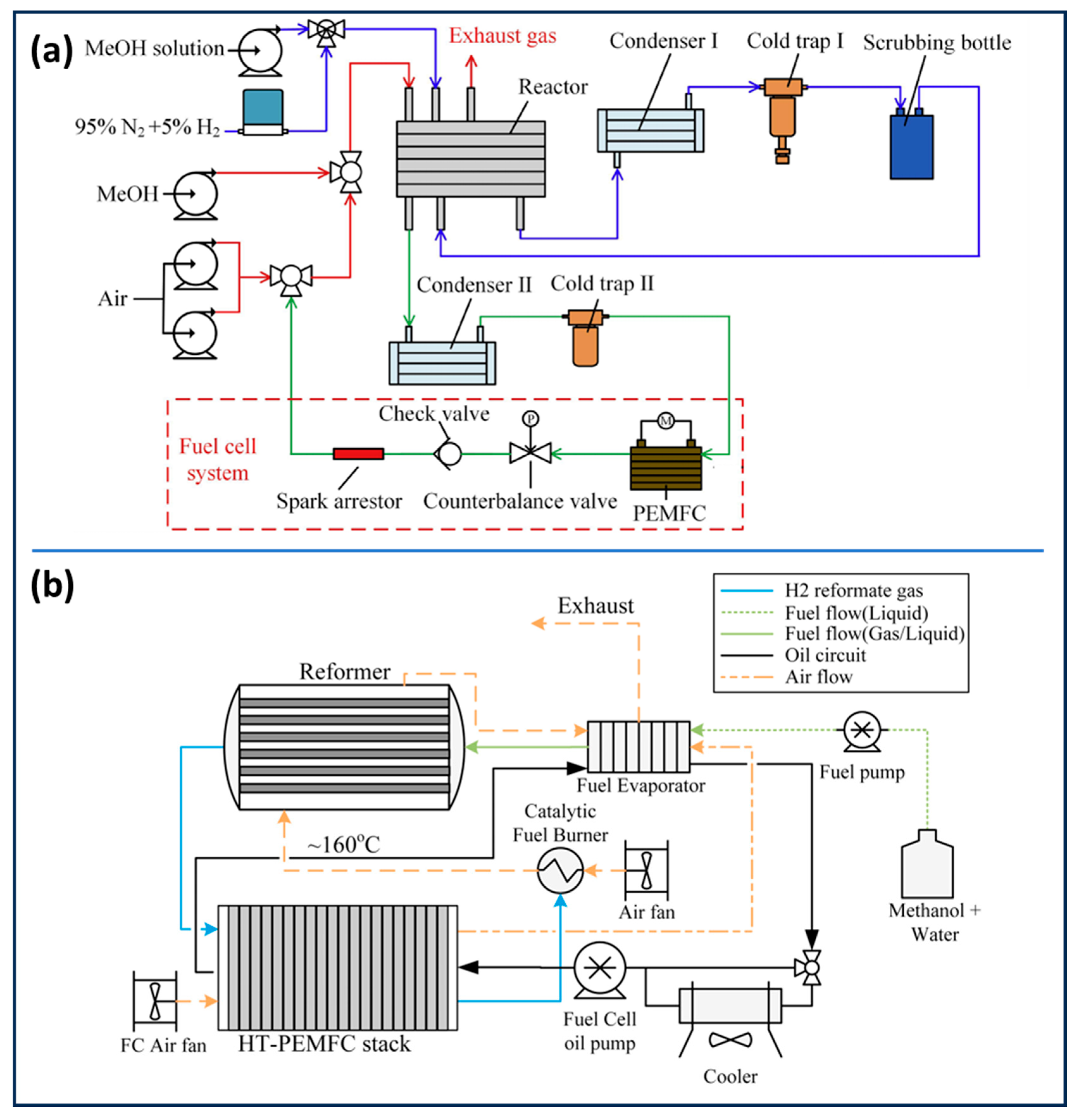
Generally, LT-PEMFCs operate with perfluoro sulfonic acid (PFSA) membranes (e.g., Nafion) as PEMs [13,14]. Hydrogen or hydrogen-rich mixtures of gases are used as fuel for the anode and air or oxygen as fuel for the cathode, and both fuels should be in continuous supply. In particular, LT-PEMFCs are susceptible to impurity and consequently require high-purity hydrogen (99.9999%), and the cost is very high [15]. Hydrogen fuel can be produced using a variety of resources, including biomass, fossil fuels, and water electrolysis [16,17,18]. Furthermore, the lack of transportation infrastructure for hydrogen transfer and refueling is one of the main obstacles preventing the commercial marketing of hydrogen-fuel-cell automobiles and other applications. While methanol is more cost-effective than the hydrogen and much simpler to transport and store, using it in LT-PEMFCs with reformed hydrogen is difficult because its carbon monoxide content must be less than 10 ppm to prevent serious active site poisoning [19,20,21,22,23,24]. Beyond that, its temperature has to be decreased from its reforming temperature, which is >200 °C, to the operational condition of LT-PEMFCs (~85 °C) (Figure 2a) [25,26,27]. Initially the reformate gas is cooled down by condenser I, and the methanol from the reformate gas is separated by cold trap I. The reformate gas is then cleaned through a scrubbing bottle. After that, the reformate gas enters the methanation chamber to lower the carbon monoxide concentration. Condenser II further cools the reformatted gas across from the methanation chamber, which has a much lower carbon monoxide concentration; additionally, vapor separation occurs in cold trap II. Because of the complicated nature of these devices with cooling, vapor formation, and carbon monoxide cleaning requirements, there is a great need for fuel cells working at elevated temperature with improved CO tolerance, without the requirement for carbon monoxide purification and thermal utilization for evaporation [28,29]. HT-PEMFCs generally provide greater energy efficiency with a wider range of fuel alternatives and can employ low-noble metal and non-noble metal catalysts. A PEMFC working at 100–300 °C is capable of (i) improving the kinetic reaction with a low loading of noble metal and non-noble metal catalysts in the hydrogen oxidation reaction (HOR) and oxygen reduction reaction (ORR); (ii) enhancing tolerance to catalyst poisoning by CO, NOx, sulfur oxide, and hydrogen sulfide, with possibilities involving low-purity hydrogen; (iii) facilitating the transfer of heat without liquid water complications; and (iv) improving the thermodynamic property of the generated heat [30,31,32,33,34,35,36,37]. In HT-PEMFCs, a mixture of methanol and water can be employed as fuel, which is injected into an evaporator prior to being transported to the reformer (Figure 2b). The operation of steam reforming subsequently transforms this fuel mix into a hydrogen-rich gas along with high carbon monoxide content compared with LT-PEMFCs, due to the greater CO-tolerant property of HT-PEMFCs. Additionally, this technology makes it possible to heat the evaporator by using the heat which is generated by the HT-PEMFC [38,39,40,41]. To satisfy these specifications, liquid water-free HT-PEMFCs have been established with a proton-conducting acid which has an extreme boiling temperature (such as PA and phosphate) enclosed in a thermally stable proton-conducting polymer membrane to a maximum of 400 °C [10,42]. Table 1 provides a concise comparison of the key features of LT-PEMFCs and HT-PEMFCs, highlighting the fundamental differences that motivate the distinct research and development trajectories for each technology.
These combined advantages make HT-PEMFCs a particularly compelling technology for applications where fuel flexibility, system simplicity, and robustness are paramount, such as in heavy-duty vehicles, maritime shipping, aviation, and stationary power generation [10]. They represent a strategic technological pathway for sectors where the stringent fuel purity and complex water management requirements of LT-PEMFCs pose significant economic and logistical barriers.

1.1. Working Principles and Electrochemistry of HT-PEMFCs

The structure of an HT-PEMFC basically looks the same as the traditional PEMFC, as it possesses a polymeric proton-conducting membrane positioned within an anode and cathode supporting layer, but the type of membrane used here varies (e.g., PA-PBI) (Figure 3). While the HT-PEMFC operates between 150 and 200 °C, hydrogen gas is supplied to the anode surface without humidification, and under the action of a Pt catalyst, it decomposes into protons and electrons (Equation (1)), whereas the proton and electron travel towards the cathode via a PEM and an outer circuit. In the meantime, oxygen flows to the cathode catalyst surface, and water is generated when protons and electrons react with oxygen under the action of the catalyst through the process of ORR (Equation (2)).
Anode: 2H2 → 4H+ + 4e
Cathode: O2 + 4H+ + 4e → 2H2O
Overall: O2 + 2H2 → 2H2O
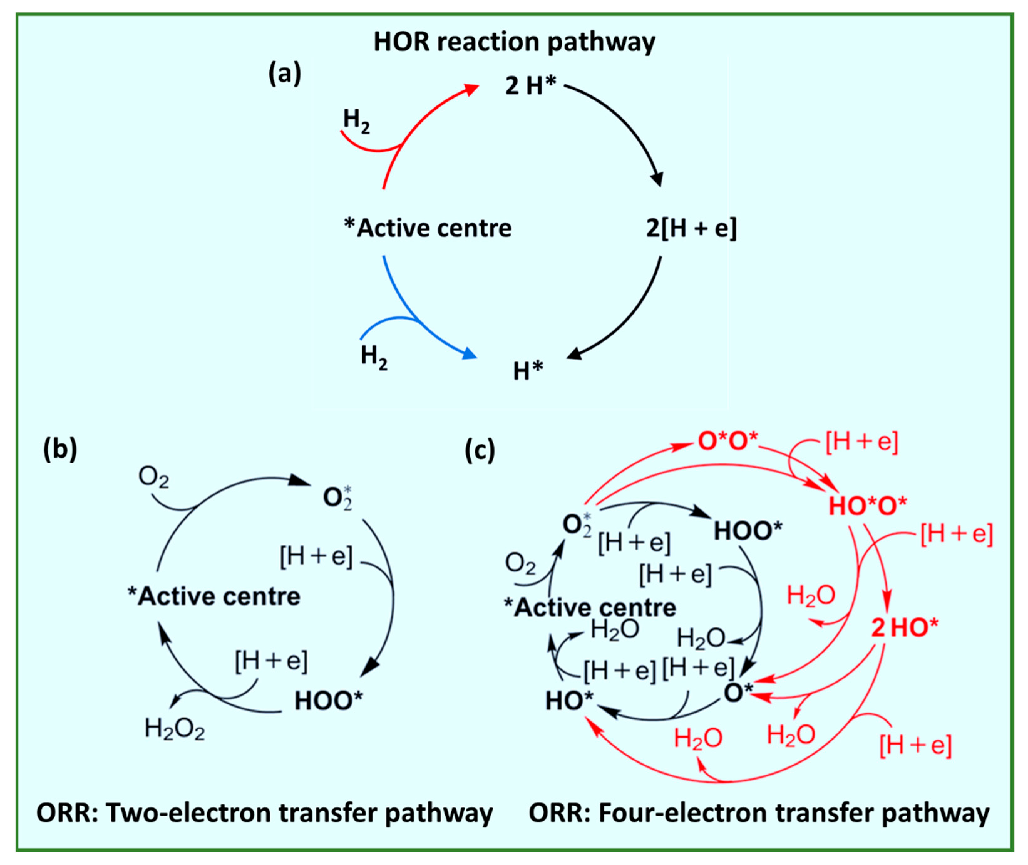
Two primary perspectives can be used to present the kinetic study of the HOR and ORR for HT-PEMFCs: the reaction routes and how they impact the response rate. Figure 4a–c show the HOR and ORR pathways [43,44]. In the specific process of the HOR, hydrogen flows into the catalyst via the catalyst layer (CL) pores and adsorbs on the active areas, weakening the H-H bond strength before breaking into the adsorbed H atom [45]. Under the influence of the water molecules and the electrode’s driving strength, the H atom loses one electron to become a proton [46,47,48]. HORs are split into two categories: the Tafel–Volmer process consisting of Tafel and Volmer steps (Equations (4) and (5)), and the Heyrovsky–Volmer process, which includes Heyrovsky and Volmer steps (Equations (6) and (7)); these steps are known as the Heyrovsky–Tafel model [49,50].
HOR: H2 2H+  + 2e
Tafel step: H2 → 2H*
Heyrovsky step: H2 → H* + H+ +e
Volmer step: H* → H+ + e
In HT-PEMFCs, the ORR is typically broken down into three primary processes: (i) oxygen initially diffuses and adsorbs over the catalyst’s surface; (ii) electrons move toward the adsorbed oxygen molecules via the electrode, and during this time, the O-O bond breaks down; and (iii) the resultant substance exits from the electrolyte [52,53]. Additionally, the ORR at increased temperatures may be classified into two primary categories, equivalent to LT-PEMFCs, two-electron transfer (Equation (8)) and four-electron transfer (Equation (9)), as illustrated in Figure 4b,c. Due to partial reduction of O2 to H2O2, the former lowers the catalyst selectivity and is detrimental to the performance of HT-PEMFCs. In contrast, the latter facilitates the ORR process by reducing O2 into H2O. There are many oxygen-containing substances involved in the ORR process in the two-electron pathway, such as OOH*, O*, and OH* [49,54]. The overall reaction rate is determined by the voltage needed to convert the intermediates [51,52].
ORR:
Two-electron transfer: O2 + 2H+ + 2e → H2O2
Four-electron transfer: O2 + 4H+ + 4e → 2H2O
The Butler–Volmer (B–V) equation, activation energy, and activation overpotential are frequently employed to assess the kinetic rate in HT-PEMFCs [55]. The energy threshold that should be crossed during the reactant-to-product conversion process is known as activation energy, and it is mostly influenced by the three-phase area. In principle, the faster the reaction rate, the lower the activation energy. The activation overpotential’s value is mostly determined by the reactive substance’s activity, which is determined by certain conditions. Along with the previous two factors, a theoretical base for the predictions of kinetic changes is provided by the Butler–Volmer (B–V) equation (Equation (10)). This might be acquired through exchange current density calculation processes.
j = j 0 exp α a n F ƞ R T e x p α c n F ƞ R T
where j0—exchange current density; αa—anodic charge transfer coefficient; and αc—cathodic charge transfer coefficient.

1.2. Problem Associates with PGM Catalyst in HT-PEMFCs
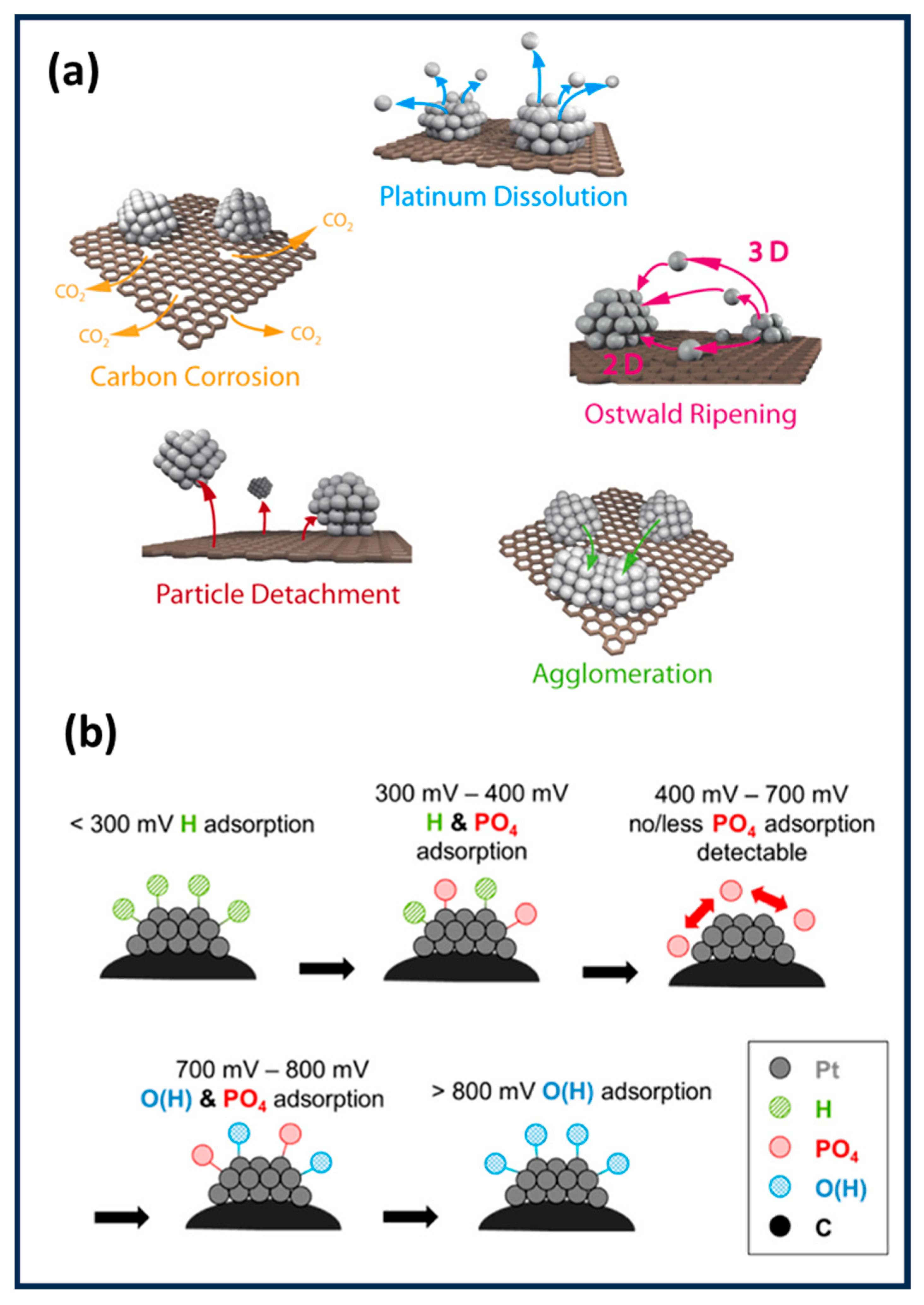
For decades, platinum (Pt) and its alloys, typically dispersed as nanoparticles on a carbon support (Pt/C), have been the undisputed state-of-the-art electrocatalysts for PEMFCs. One of the primary causes of HT-PEMFC performance losses is the degradation process of platinum (Pt) and platinum-group metal (PGM) catalyst, which is similar to LT-PEMFCs (Figure 5a). Meanwhile, the existence of PA at higher operational temperatures complicates catalyst degradation [56,57]. The acidic atmosphere of HT-PEMFCs leads the platinum particles to gradually dissolve into Pt2+ ions and then redeposit on already existing Pt nanoparticles, creating large-diameter nanoparticles and reducing the amount of active surface area [38,56,58]. The dissolved nanoparticles migrate to other regions of the MEA that are inaccessible to reactant gases [59,60]. The action of dissolution, migration, and redeposition of Pt nanoparticles that results in the formation of nanoparticles is called Ostwald ripening [61,62,63]. Furthermore, the neighboring platinum nanoparticles diffuse to create larger nanoparticles, and this process is called platinum agglomeration [64]. This process occurs more quickly whenever the size of particles is smaller because of the larger Gibbs free energy [65]. The gradual increase in the size of platinum particles will reduce the electrochemical surface area (ECSA) and performance of fuel cells. The Pt particles are dissolved according to the following equations [66,67] under open circuit voltage (OCV) conditions:
Pt + H2O → PtO + 2H+ + 2e
PtO + 2H+ + 2e ↔ Pt2+ + H2O
Another cause of degradation in HT-PEMFCs is carbon support corrosion, which may lead to the separation and aggregation of catalyst particles [68,69]. In particular, during the operation of HT-PEMFCs, the bombardment of certain energetic free radicals causes the corrosion of the carbon support. Water with a high potential frequently produces these energetic free radicals. When the potential rises, these free radicals oxidize to more stable oxides. This specific phenomenon of carbon corrosion is shown in the following equation [10]:
C* + H2O → C-OH + H+ + e (E = 0.20 V vs. RHE)
C-OH → C = O + H+ + e (E = 0.80 V vs. RHE)
C-OH + H2O → C* + CO2 + 3H+ + 3 e (E = 0.95 V vs. RHE)
Another potential problem with HT-PEMFCs is phosphate adsorption over the Pt catalyst, which hinders the sites of reaction and inhibits the HOR and ORR processes [70,71,72,73]. Phosphate molecule adsorption on the cathode electrode is influenced by temperature and voltage potential. Figure 5b is a schematic diagram of potential dependency. Adsorption of hydrogen exists just below 300 mV, while adsorption of oxygen does above 800mV. Phosphate adsorption occurs between voltages of 300 and 800 mV, and this voltage range diminishes as the temperature increases [70,74]. Although phosphate adsorption also takes place at the anode electrode, it does not poison the catalyst and might potentially help to stabilize hydrogen adsorption. CO in the anode gaseous supply can boost phosphate adsorption, and at the same time, the existence of water reduces coverage [72,75].
Figure 5. Degradation mechanisms in fuel-cell catalysts. (a) Pt nanoparticle deterioration on carbon support under operational stress [76]. Reproduced with permission. Copyright 2014, Elsevier. (b) Voltage-dependent adsorbate deposition behavior on Pt surfaces. Reprinted/adapted with permission from Ref. [70]. Copyright 2016, American Chemical Society.
Catalysts 15 00775 g005
The platinum problem in High-Temperature Proton-Exchange Membrane Fuel Cells (HT-PEMFCs) is surprisingly complicated, as the higher operating temperature enhances the intrinsic kinetic activity of platinum (Pt), but this benefit is largely exceeded by severe poisoning effects from the phosphate (PA) electrolyte [77]. Phosphate anions strongly adsorb onto the Pt surface, blocking active sites and inhibiting the oxygen reduction reaction (ORR) [78], which necessitates much higher platinum loadings in HT-PEMFCs—often exceeding 1.0 mg of Pt per square centimeter—compared with the 0.1–0.4 mgPtcm−2 typical for the low-temperature counterparts. This counterintuitive requirement negates the kinetic advantage of high temperature and significantly increases costs, making the development of non-precious metal (NPM) catalysts not only desirable but essential to the economic viability of HT-PEMFC technology. Despite advances in NPM catalysts with improved activity and durability, their commercial adoption remains limited by critical challenges such as uncertainties in large-scale synthesis, batch-to-batch reproducibility, and long-term stability under real operating conditions. Additionally, the cost-effectiveness of these catalysts must be evaluated not only in terms of material costs but also with regard to electrode processing, system integration, and maintenance. This review provides a comprehensive assessment of NPM catalysts by analyzing their electrochemical performance under HT-PEMFC conditions while addressing challenges related to scale-up, manufacturing consistency, and techno-economic viability. By bridging the gap between laboratory-scale development and commercial application, this work contributes to advancing low-cost, sustainable, high-performance fuel-cell technologies, ultimately fostering the development of cost-effective, durable, and efficient HT-PEMFC systems.

2. Types of Non-Precious Metal (NPM) Catalysts

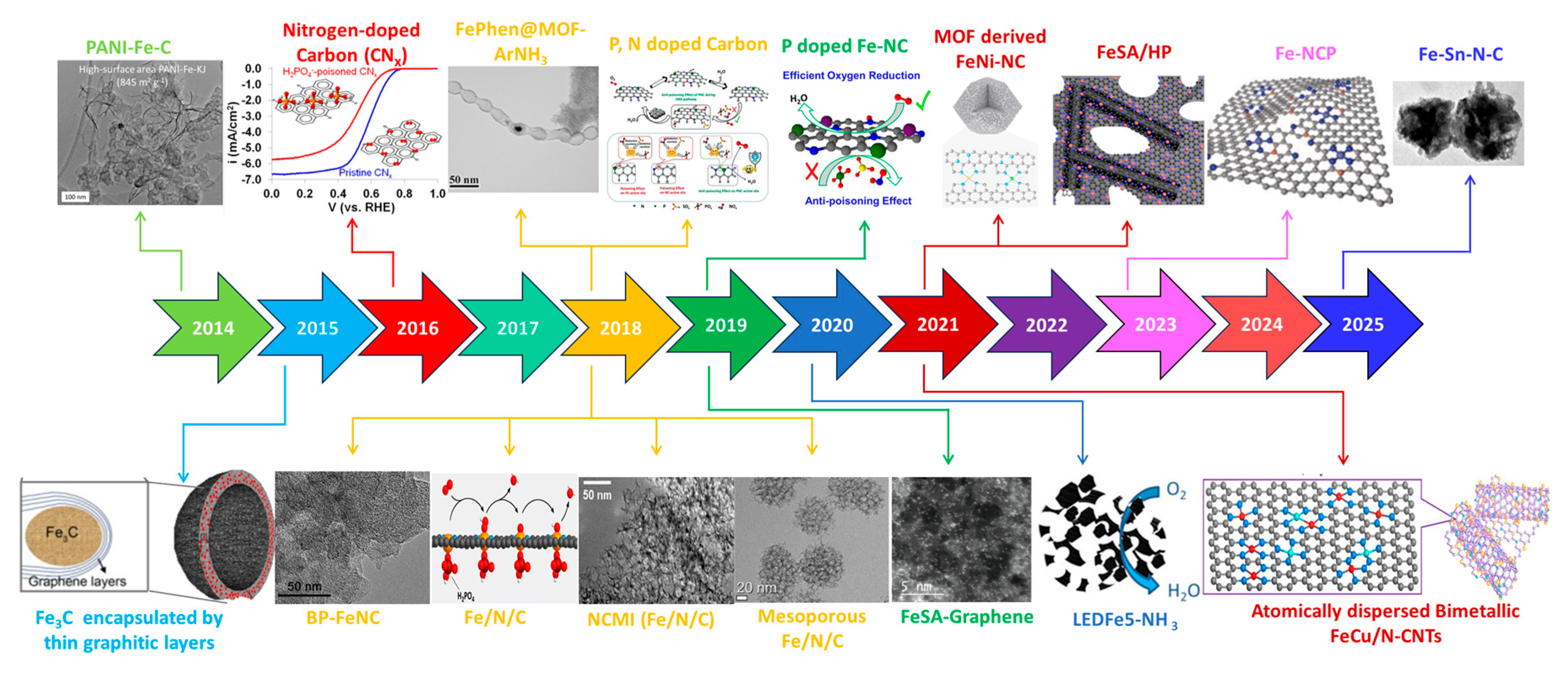
The high loading of Pt-group metal catalysts is required to increase the possibility of using HT-PEMFCs for real-world applications because of the phosphate chemisorption of Pt-based catalysts at cathode electrodes. The expensive price, limited availability, and inadequate catalytic area in a PA environment has motivated research and development of NPM catalysts for HT-PEMFCs. NPM catalysts with affordable price, easily obtainable and widely available materials, and simplicity in fabrication have received significant interest in recent years. A timeline chart illustrating the advancements in NPM catalysts for HT-PEMFCs is shown in Figure 6. In 2014, the first report of an NPM catalyst made for ORR applications to use as a cathode electrode in HT-PEMFCs was published [79,80,81]. Over a decade, NPM catalysts have been studied for HT-PEMFCs and have shown substantial enhancement in performance, long-term stability, and operational efficiency. Above all, the NPM catalysts’ stability in HT-PEMFCs is significantly better than in LT-PEMFCs [82,83,84,85].

2.1. Transition Metal Catalysts

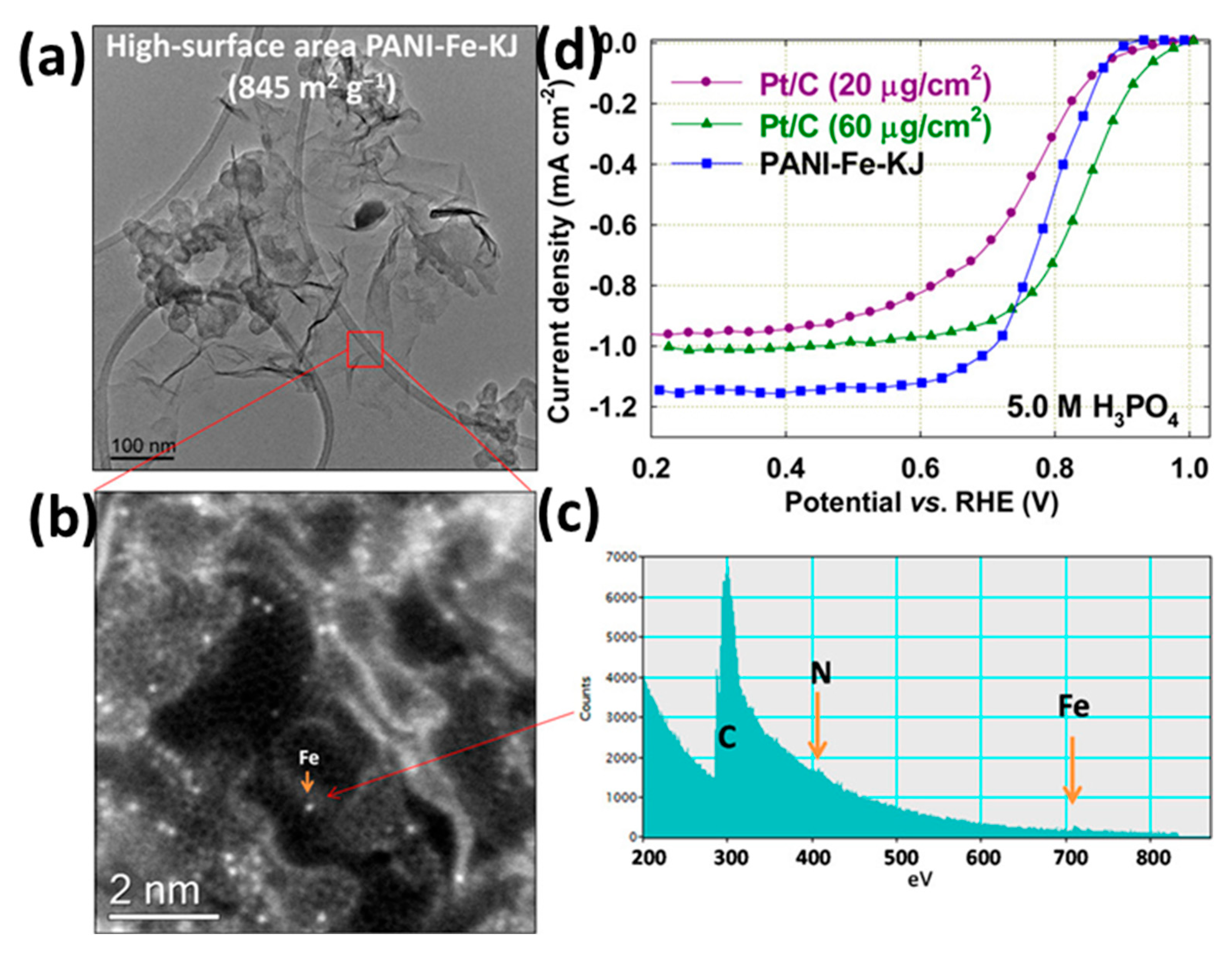
The high Pt loading required at the cathode to overcome the slow kinetics of the ORR is a major challenge for conventional HT-PEMFCs. Consequently, developing NPM catalysts is crucial to reducing the reliance on Pt. Among these, earth-abundant transition metals like Mn, Fe, Co, and Ni are promising candidates due to their affordability, stability, and good ORR activity [86,87,88]. An early and effective approach involved creating active sites by pyrolyzing nitrogen-containing polymers with a metal precursor. For instance, Zelenay et al. [79] developed a notable PANI-Fe-C catalyst by polymerizing aniline on a carbon support in the presence of an iron precursor, followed by high-temperature pyrolysis and an acid leaching step to remove unstable species. The resulting high-surface-area catalyst (845 m2/g, Figure 7a–c) demonstrated superior ORR performance and excellent tolerance to phosphate ions in 5.0 M PA, even outperforming a conventional Pt/C catalyst (Figure 7d).
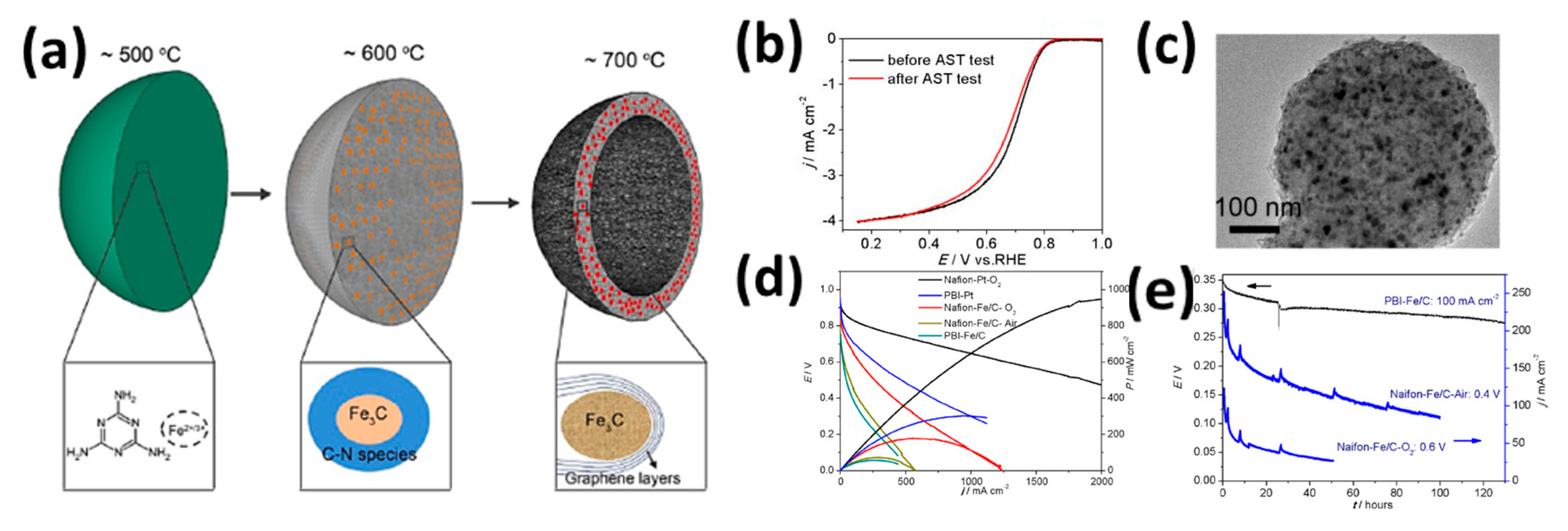
Building on these foundational strategies, subsequent research has focused on creating specific and highly stable active phases, such as metal carbides, to enhance durability and performance. Li et al. [82] exemplified this by preparing Fe3C nanoparticles encapsulated in graphitic shells via a one-step pyrolysis method using ferrocene and cyanamide. They found that a pyrolysis temperature of 700 °C was optimal for creating hollow microspheres where active Fe3C nanoparticles were protected by a thin graphitic layer (Figure 8a). This protective shell proved critical to durability, as shown by a 2000-cycle accelerated stress test (AST) in a half-cell (Figure 8b), with Transmission Electron Microscopy (TEM) analysis confirming minimal structural change post-test (Figure 8c). When tested in an HT-PEMFC, the catalyst’s performance significantly improved by raising the operating temperature from 120 °C to 180 °C, achieving a peak power density of 60 mW/cm2, and showing reasonable long-term stability (Figure 8d).
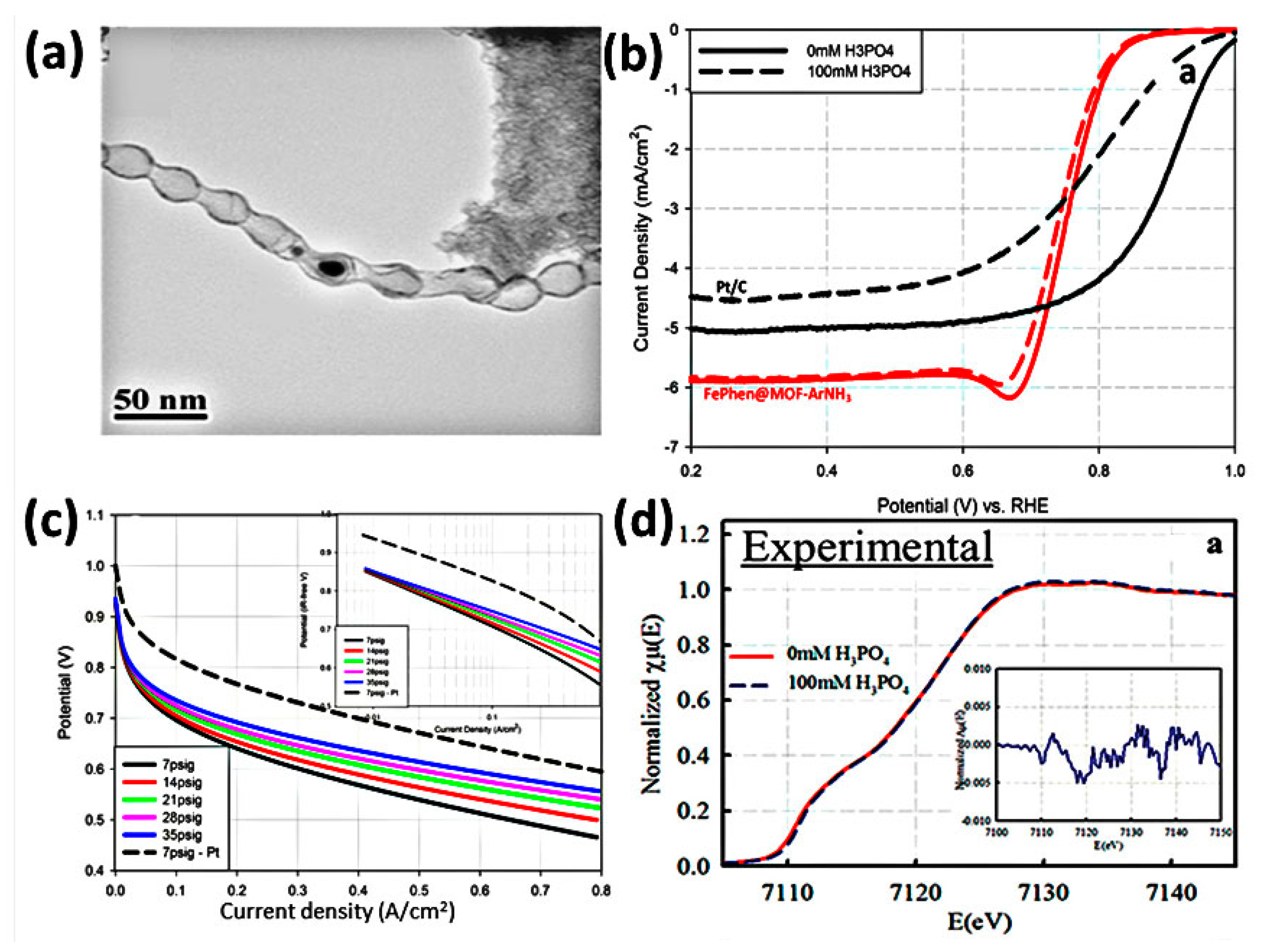
A more advanced strategy for creating uniformly distributed active sites involves using Metal–Organic Frameworks (MOFs) as sacrificial templates. This method offers precise control over the final catalyst’s structure and porosity. Illustrating this, Strickland et al. [89] developed an FePhen@MOF-ArNH3 electrocatalyst that showed bamboo-like carbon nanotube (CNT) morphology (Figure 9a) and minimal activity loss compared with Pt/C in a PA environment (Figure 9b). To understand the catalyst’s structural and electronic properties and its interaction with phosphate anions, the team employed in situ X-ray absorption spectroscopy (XAS) and the Δμ method (Figure 9d). This detailed characterization supported the observation of excellent single-cell HT-PEMFC performance at 200 °C in both pure oxygen and air (Figure 9c).
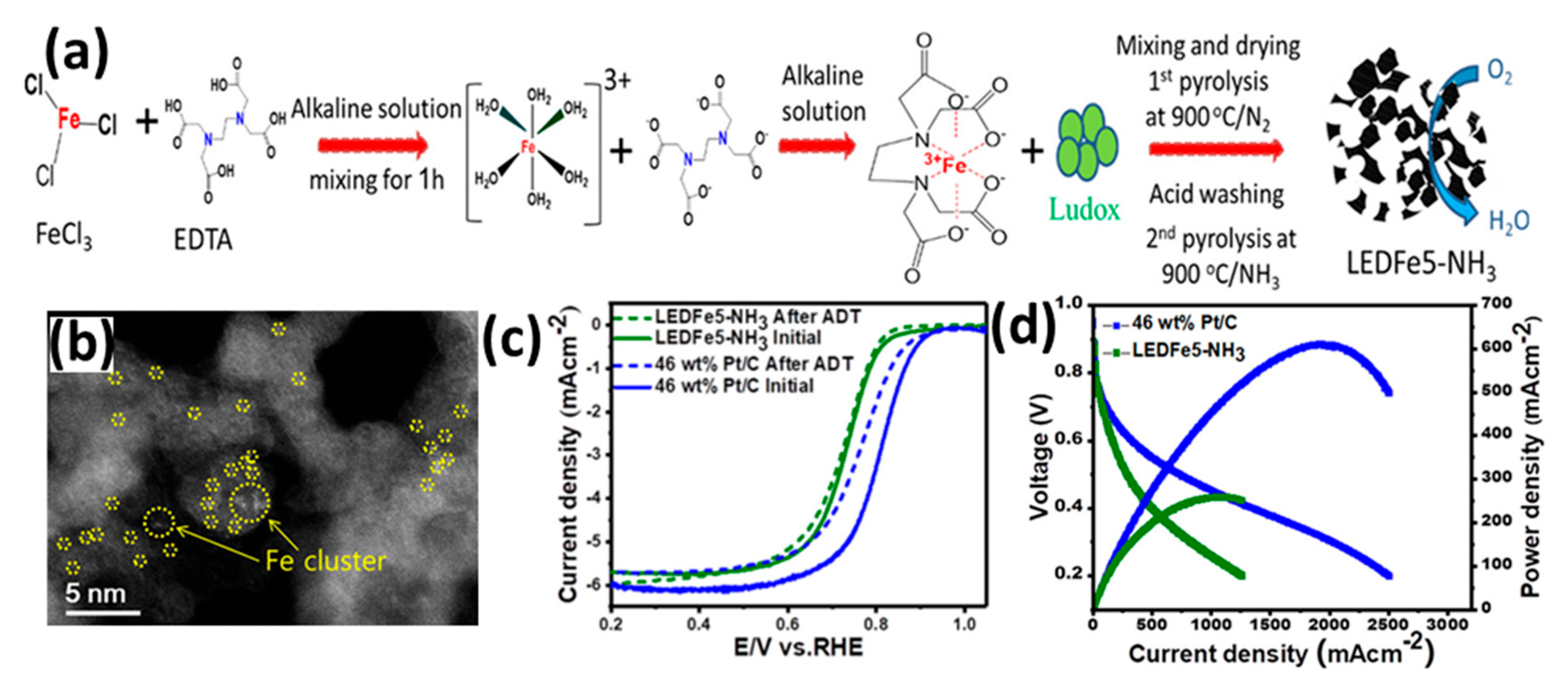
Pushing the boundaries of catalyst design further, another key direction is maximizing atom efficiency through the development of single-atom catalysts (SACs). These catalysts aim to create the highest possible density of active sites. In a pioneering study, Yu et al. [90] synthesized microporous/mesoporous catalysts (LEDFe5-NH3) using an organometallic EDTA-Fe complex as a precursor (Figure 10a). Characterization revealed that iron was distributed as both single atoms (Fe-Nₓ sites) and nanoparticles within the N-doped carbon matrix (Figure 10b). This unique structure, combining high porosity with highly effective single-atom Fe-Nₓ sites, resulted in outstanding ORR activity and remarkable durability, withstanding 30,000 potential cycles in half-cell tests (Figure 10c). When integrated into an HT-PEMFC, the catalyst also showed excellent performance, attributed to its superior active site density compared with traditional Pt/C (Figure 10d).

2.2. Metal–Nitrogen–Carbon (M-N-C) Catalysts

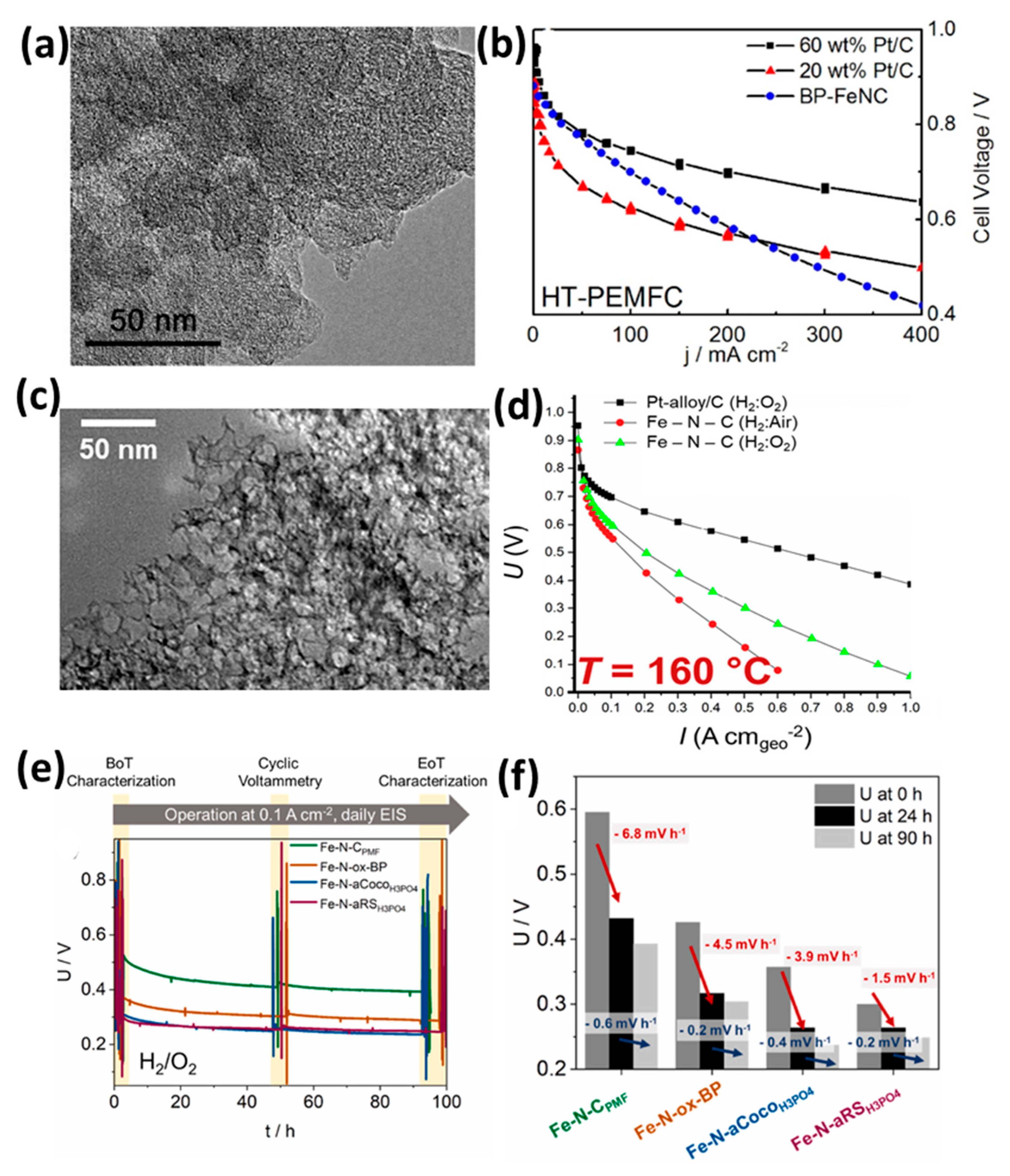
Among the various PGM-free catalysts explored for HT-PEMFCs, those based on M-N-C have emerged as the most viable alternatives to conventional Pt/C. In particular, catalysts featuring atomically dispersed Fe-Nₓ moieties have demonstrated significant potential, attracting considerable research interest in recent years [85,91,92,93]. Pioneering studies by Gokhale et al. and Hu et al. [94,95] in 2018 first demonstrated the application of Fe-N-C cathodes in HT-PEMFCs (Figure 11a–d). Their findings revealed a common challenge: while performance was comparable to Pt/C at low current densities (<100 mA cm−2), significant voltage losses occurred at higher densities. This drop was attributed to mass transport limitations, a consequence of the catalyst’s lower volumetric activity which necessitated thick catalyst layers (CLs) with high loadings (e.g., 2 to 7.8 mg cm−2), which impede oxygen flow.
The critical role of mass transport was further highlighted by subsequent research. For instance, Byeon et al. [97] observed very poor performance from an Fe-N-C catalyst (Figure 11e,f), which they linked to substantial mass transport resistance caused by an exceptionally high catalyst loading of 21 mg cm−2. In a more detailed comparative study, Bevilacqua et al. [98] employed electrochemical impedance spectroscopy (EIS) and distribution of relaxation times (DRT) analysis. They quantified that an Fe-N-C-based membrane electrode assembly (MEA) exhibited 2.5 times greater resistance than its Pt/C and PtCo/C counterparts. This was ascribed to a combination of restricted O2 diffusion and hindered access of the PA electrolyte to the active Fe-Nx sites.
Beyond initial performance, the long-term durability of Fe-N-C catalysts, particularly the stability of the carbon support and active sites, is a major area of investigation. To this end, Schmies et al. [96] investigated the stability of four distinct Fe-N-C catalysts with varying carbon support properties. A crucial finding was the dramatic voltage drop—up to 27%—within the first 24 h of a 90 h constant load test. Post-mortem and operando analyses identified two primary degradation mechanisms: the corrosion of the carbon support and the deactivation or loss of active Fe-Nx sites, likely via dissolution into metal clusters or oxides. Interestingly, DRT analysis also detected a temporary activation effect attributed to improved electrolyte distribution, but this slight improvement was ultimately overshadowed by the continuous degradation of active sites.
Collectively, these studies illustrate a clear research trajectory. While Fe-N-C catalysts are promising, overcoming challenges related to mass transport and long-term durability is essential [99,100]. The detailed electrochemical and physical characterization methods employed in these research studies are paving the way for the rational design of more robust and high-performance Fe-N-C catalysts for HT-PEMFCs.

2.3. P-Doped Metal–Nitrogen–Carbon (M-N-C) Catalysts

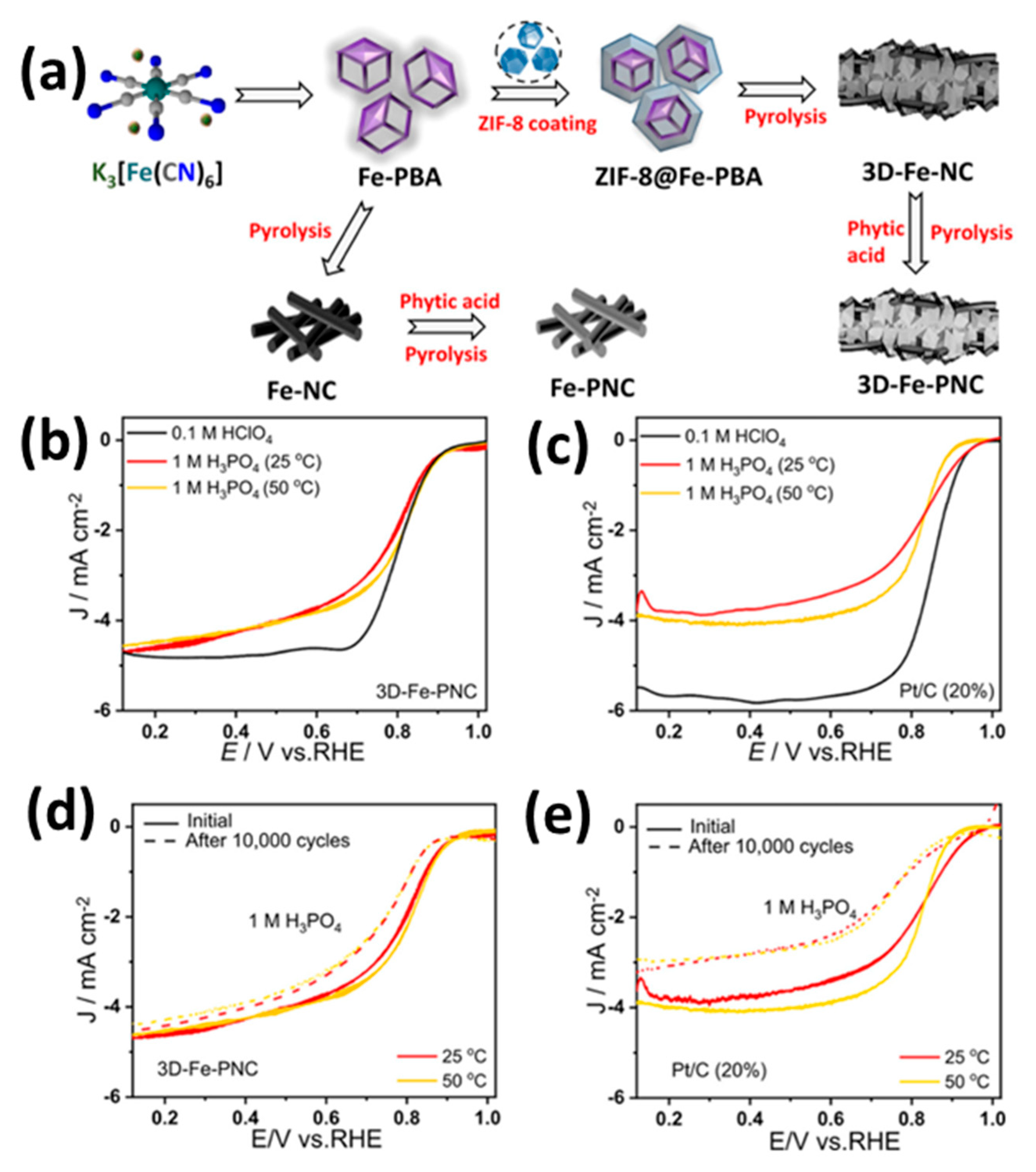
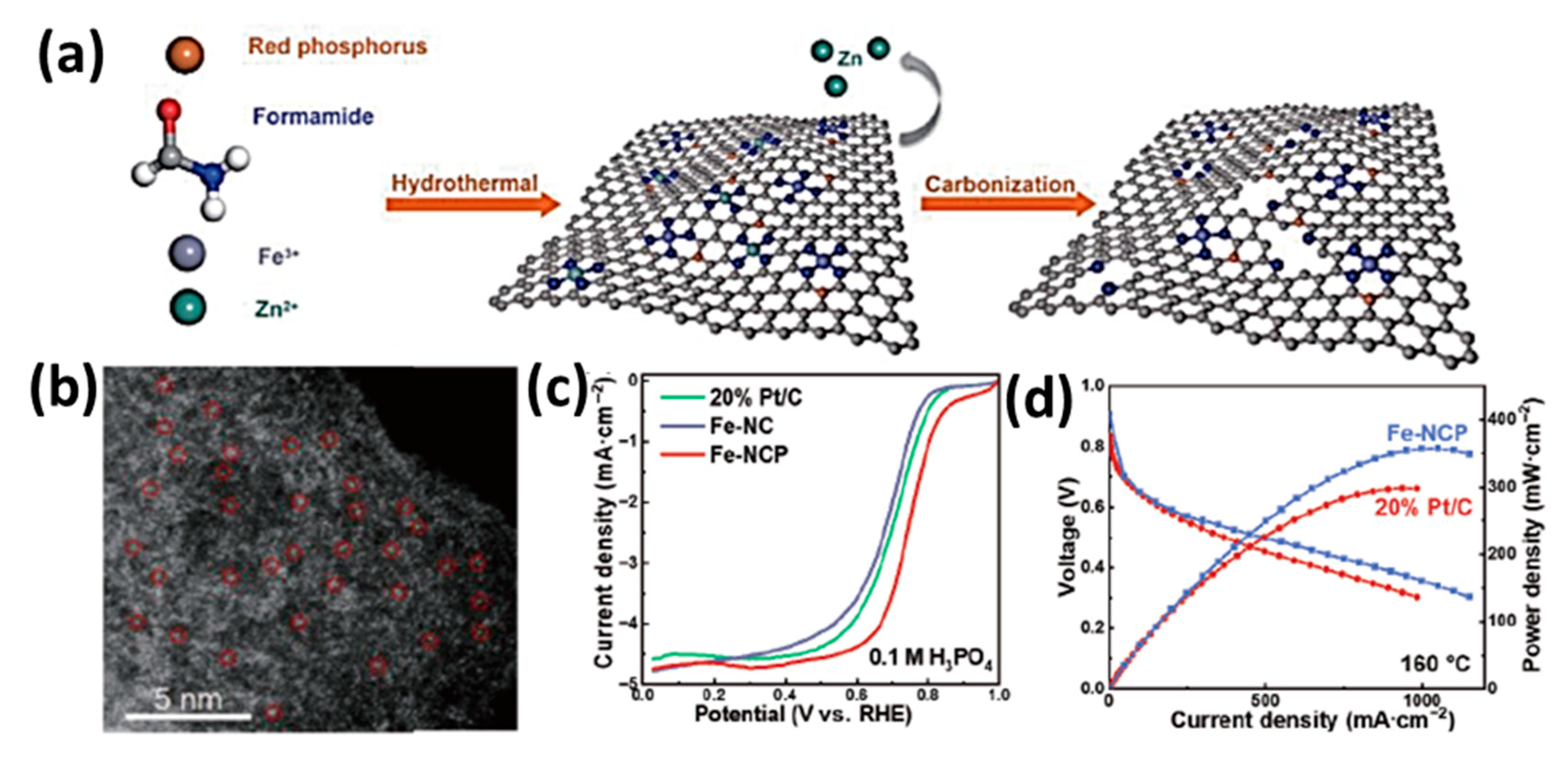
The loading of Fe in the catalyst can currently reach up to 5 to 10 weight percent, which is challenging to increase further due to four pyridinic/pyrrolic N atoms and a minimum of ten C atoms being required to stabilize a single Fe atom. To extensively boost the ORR activity and TOF of Fe-N4 sites is very important. Substituting a Cu atom next to Fe-N4 may alter the electronic configuration of core Fe and considerably accelerate the ORR. These successful methods of controlling the configuration and functionality of single-atom catalysts by nearby metal atoms or heteroatoms inspired many researchers. Wei et al. also demonstrated that P-doping the Fe-N-C catalyst enhances the ORR activity along with providing high tolerance against small molecules, e.g., SOx, NOx, and POx (Figure 12). The synthesis process of the 3d-Fe-PNC catalyst is shown in Figure 12a. The P-doping process significantly improves the catalytic activity because of the synergistic effect of P to N that provide a more stable active region for the ORR. As a result of the above advantages in contrast with 3D-Fe-NC and Pt/C, 3D-Fe-PNC demonstrated superior ORR activity in alkaline/acidic solutions (Figure 12b–e). Furthermore, 3D-Fe-PNC exhibited a potent anti-poisoning activity when exposed to several anions, including SOx, NOx, and POx [101,102,103]. Sun et al. established a novel single-pot process to obtain P-doped Fe-N-C (Fe-NCP) catalysts, utilizing an Fe precursor, formamide (FA), and red phosphorous as starting substances (Figure 13a,b). When red phosphorous reacts with FA, it forms a chemical link to the condensation product, which additionally acts as a multidentate ligand to efficiently bind Fe atoms. An atomically scattered Fe-N4 site with a nearby P atom was produced resulting from the pyrolyzing procedure. The Fe-NCP catalyst outperforms the Fe-NC catalyst and Pt/C in HT-PEMFCs at 160 °C (357 mW/cm2; Figure 13c,d). In addition to increasing the ORR activity, the nearby P might effectively raise the charge density of Fe and support the phosphate tolerance of Fe-N4, which would also prevent Fe-N4 poisoning [104]. According to the above studies, the P-doping-against-phosphate approach offers a novel catalyst design that could be a potential pathway and makes it possible to effectively promote the active site in an environment of PA-based HT-PEMFCs.

2.4. Multi-Metallic M-N-C Systems

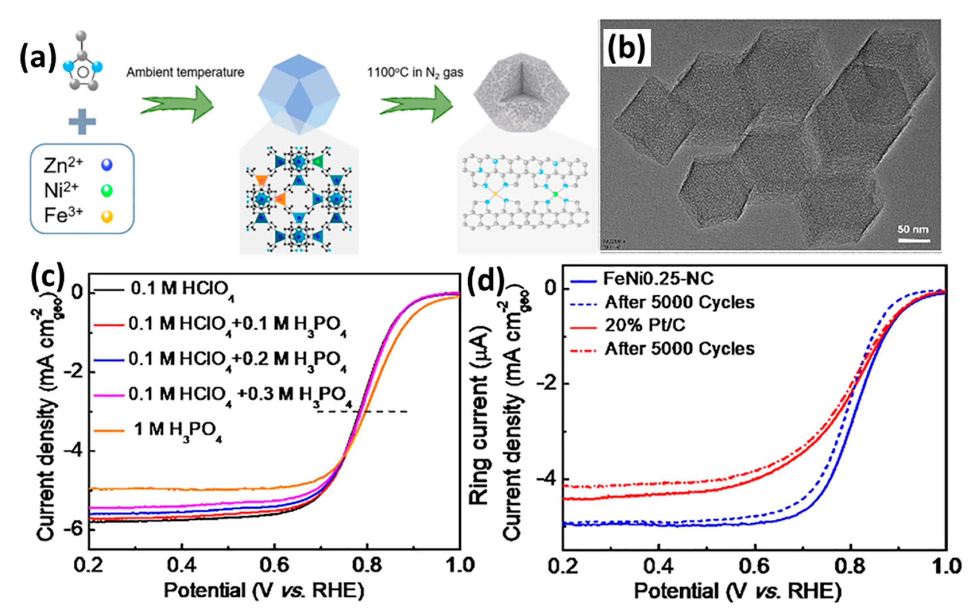
Introducing an additional metal species to create bi-metallic (typically expressed as M1M2-N-C) or multi-metallic active sites is a preferable way in order to modify the electronic configuration and enhance the efficiency of M-N-C catalysts for ORR performance [105,106,107]. Computational calculation studies on combinations of Fe and Co reveal that Fe-N4 and Co-N4 moieties possess significant binding strength with O2, and it estimated that they represent more active catalysts for ORR [108,109,110,111]. Therefore, very few studies had been conducted on M1M2-N-C. Jiang et al. synthesized dual atom (Fe, Ni)–nitrogen-doped carbon (FeNi-N-C) effectively through the simple pyrolyzing of Fe, Ni co-doped ZIF-8 (Figure 14a,b). The obtained FeNi0.25-N-C catalyst was used for ORR performance, and it showed superior activity in the PA electrolyte compared with Pt/C (Figure 14c,d), due to exceptional tolerance of phosphate ions by Fe and Ni active regions. A systematic evaluation shows that Ni improved the ORR activity and longevity of Fe-N-C in two ways. On the one hand, Ni-N and Fe-N moieties work together to improve the ORR, particularly in the high ORR overpotential region. On the other hand, Ni serves as a catalyst to facilitate graphitization and strengthen the stability of the FeNi-N-C catalyst throughout the high-temperature carbonization process. FeNi-NC has been shown to have a wide range of possible uses as an NPM catalyst in HT-PEMFCs [112,113].
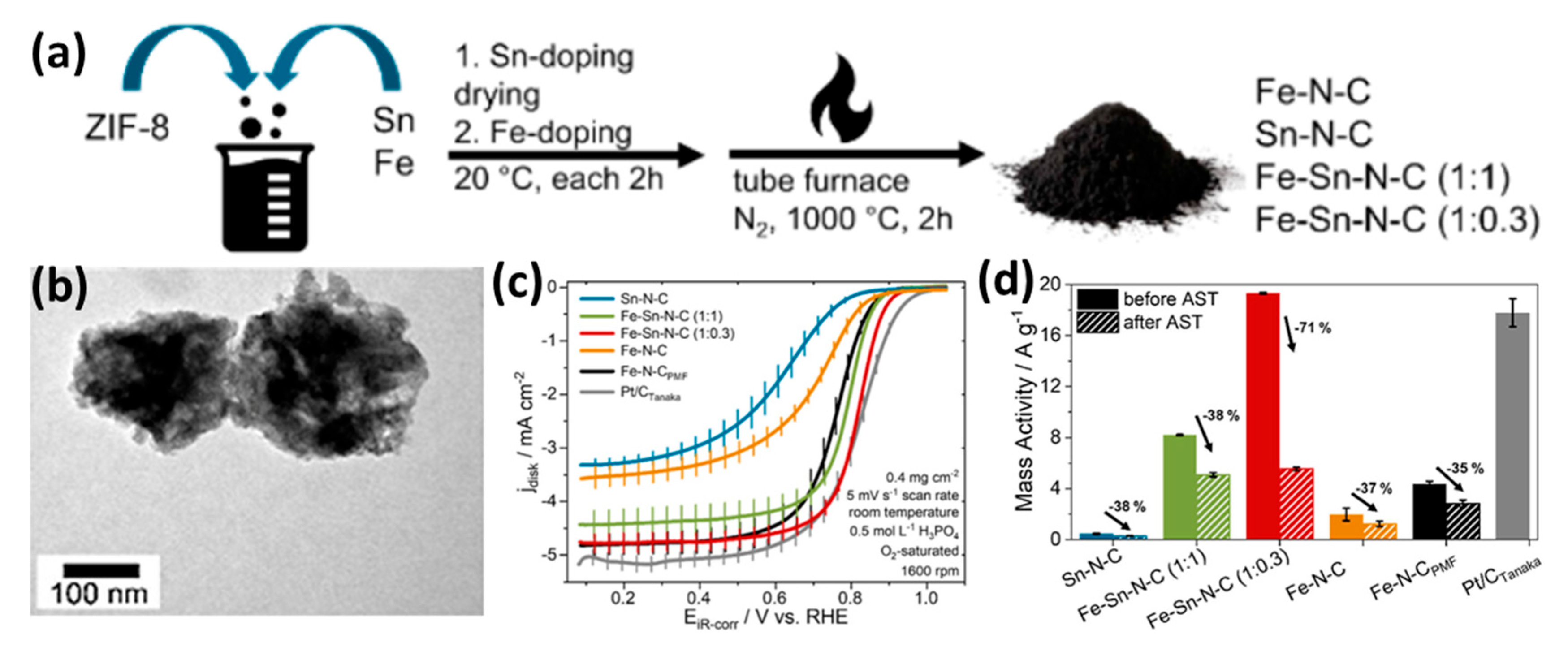
The FeSn-N-C catalyst was examined in 0.5M H3PO4 acid medium by Buschermohle et al. in contrast to monometallic-N-C (Sn-N-C and Fe-N-C) (Figure 15). The synthesized catalyst has substantially greater nitrogen content (14–20 at. %), primarily consisting of ORR active nitrogen species such as pyridinic-N, pyrrolic-N, and graphitic-N, compared with commercial Fe-N-C (7 at. %). The obtained catalyst exhibits greater ORR activity and AST stability compared with commercial Fe-N-C. An in-depth study of degradation analysis using Grazing Incidence X-Ray Diffraction (GIXRD) and X-ray absorption spectroscopy (XAS) showed that the degradation of the active site in the catalyst was due to diminished pyridinic and pyrrolic bonded nitrogen. Since there was no metallic particle formation and loss of metal, it was suspected that non-metallic nitrogen had been lost. It is suggested that dual-atom catalysts (DACs) show synergistic effects, such as the electronic impact associated with metals [114,115,116,117]. Sn may detrimentally impact the electronic conditions of redox-active Fe regions or participate as a redox-active component to facilitate the process [77], hence creating an opportunity to improve NPC material efficiency for HT-PEMFCs.

2.5. Advanced Carbon Supports

To overcome the electrochemical oxidation (i.e., corrosion) inherent in conventional carbon blacks, research has shifted towards supports with more ordered, graphitic structures [118,119]. Materials such as highly graphitized carbons, carbon nanotubes (CNTs), and graphene offer intrinsically higher resistance to the corrosive conditions of HT-PEMFCs, providing a stable anchor for catalytic active sites.
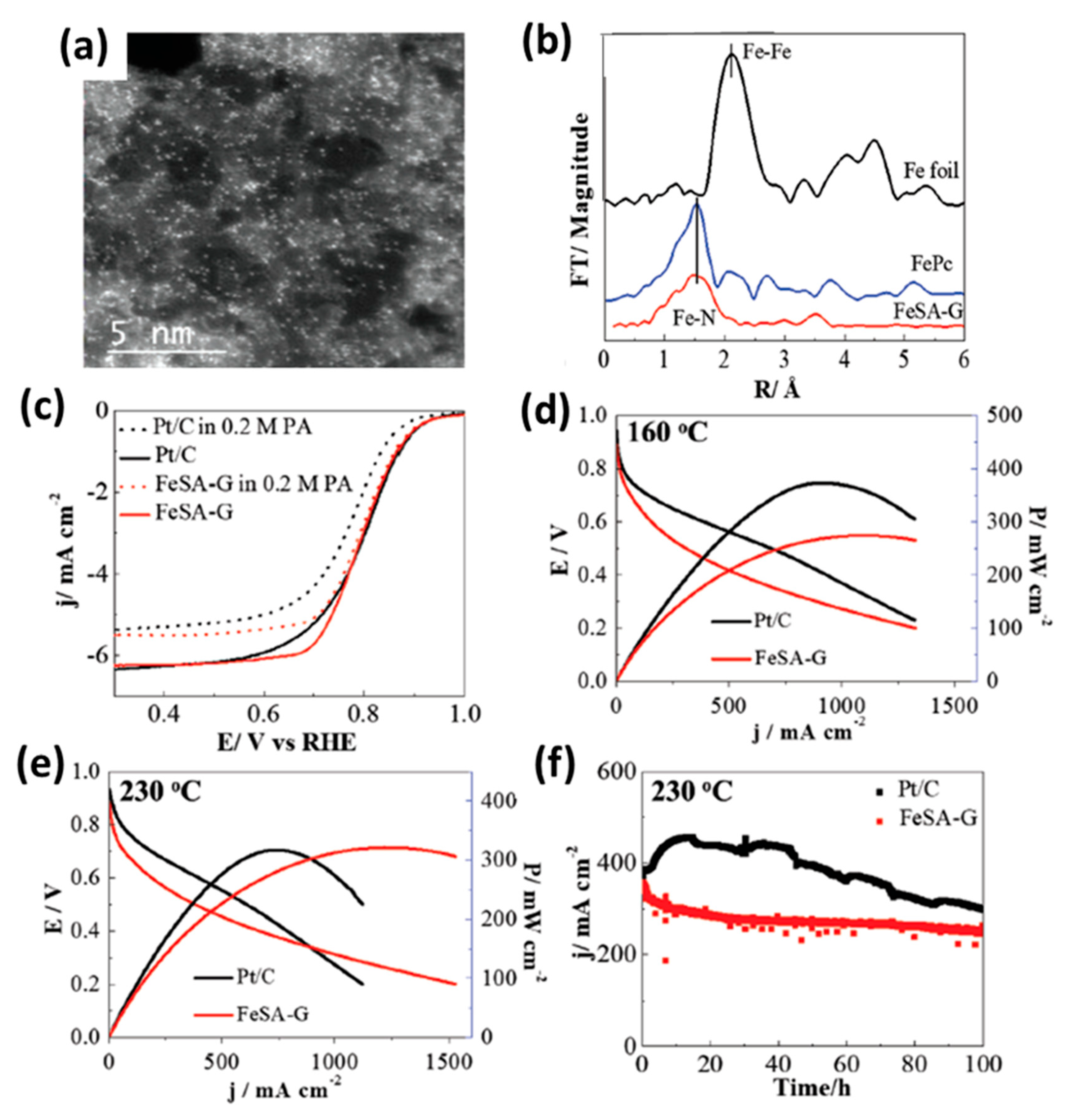
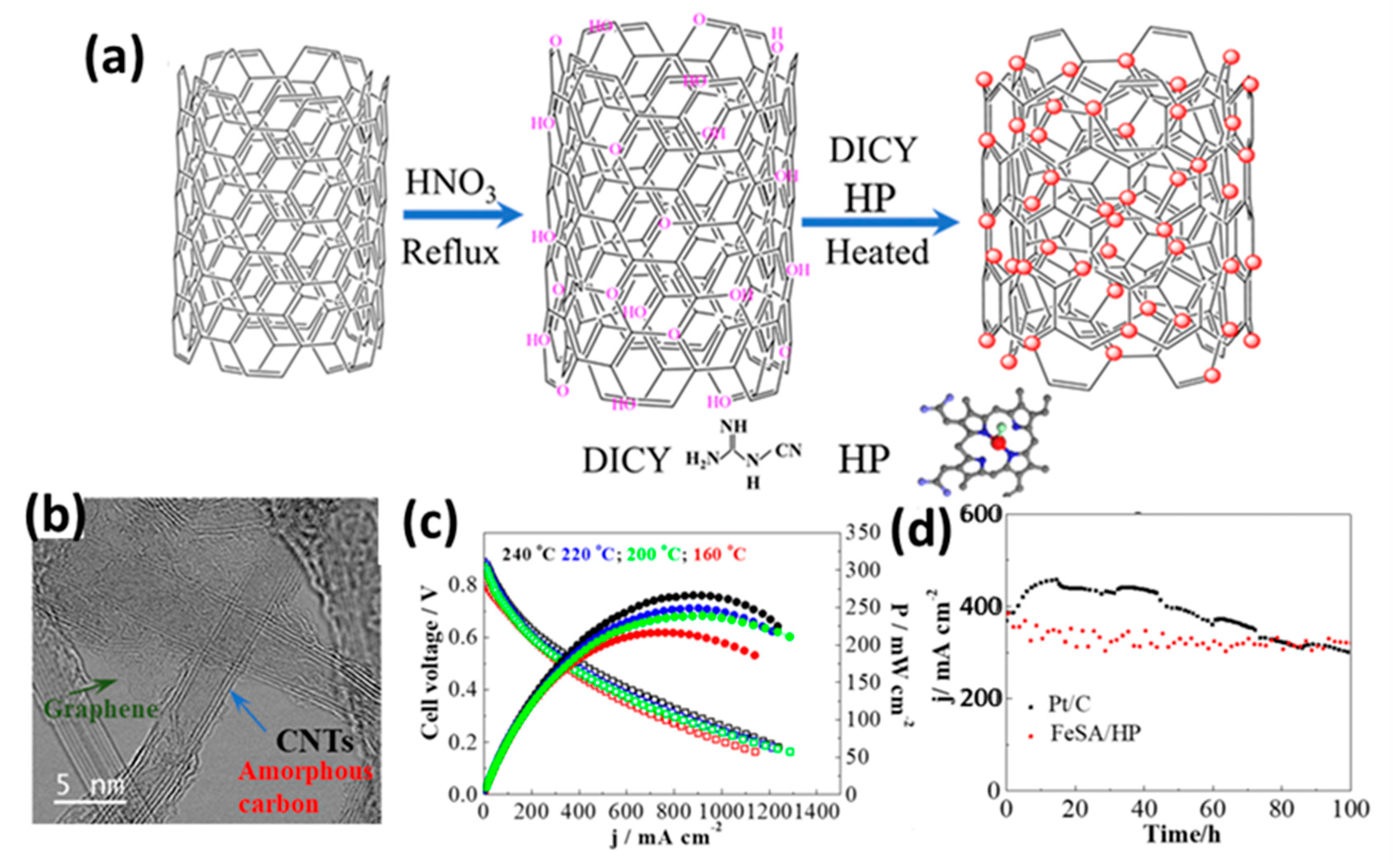
Graphene, in particular, has been leveraged as a robust support for single-atom catalysts. For instance, Jiang et al. [120] developed an iron single-atom catalyst on a graphene support (FeSA-G) via a modified one-pot pyrolysis method (Figure 16a,b). This catalyst achieved a high single-atom Fe loading of 7.7 wt.% and demonstrated ORR performance comparable to commercial Pt/C (Figure 16c,d), but with the significant advantage of superior tolerance to phosphate ions. When tested in an HT-PEMFC with a PA/PBI/SiO2 hybrid membrane at 230 °C, the FeSA-G cathode (0.3 mg/cm2 loading) delivered a peak power density of 325 mW/cm2, outperforming the Pt/C cathode (1.0 mg/cm2 loading), which reached 313 mW/cm2 (Figure 16e). Furthermore, the FeSA-G catalyst exhibited superior long-term durability (Figure 16f), highlighting its promise as a next-generation catalyst. Following a similar strategy, Cheng et al. [121] utilized highly conductive CNTs as the support material. They successfully synthesized a catalyst with iron single atoms uniformly dispersed on CNTs (FeSA-CNTs) at a loading of 3.5 wt.% (Figure 17a,b). The resulting catalyst showed excellent ORR activity, which was attributed to the combination of highly active atomic sites, inherent phosphate resistance, and the exceptional conductivity of the CNT network. In cell testing at 240 °C, the FeSA-CNT cathode delivered a peak power density of 266 mW/cm2 and demonstrated excellent long-term operational stability (Figure 17c,d).
Building on the potential of CNT supports, Wang et al. [122] introduced a novel bimetallic design, creating an atomically distributed Fe-Cu catalyst on N-doped CNTs (FeCu/N-CNTs) (Figure 18a–c). Remarkably, their work revealed a paradigm-shifting finding: contrary to its well-known poisoning effect on PGM catalysts, the phosphate anion actually enhances the ORR performance of the FeCu/N-CNT catalyst. Both experimental and theoretical analyses suggested that the strong binding of phosphate to the Cu atoms electronically modulates the neighboring Fe atoms, thereby promoting their catalytic activity. An HT-PEMFC equipped with this cathode delivered a high power density of 302 mW/cm2 at 230 °C and showed significantly better long-term stability than Pt/C (Figure 18d,e). This discovery opens an entirely new avenue for designing highly efficient and durable NPM catalysts that can uniquely leverage the chemical environment of PA-based HT-PEMFCs.

2.6. Metal-Free Heteroatom-Doped Carbon Catalysts

In acidic environments, NPM catalysts are unstable due to several consequences of degrading factors, including anion/proton binding, corrosion, and the generation of H2O2 [123,124,125]. The primary undesirable aspect of the ORR process corresponds to radical oxygen molecules that are produced by metal ions, even in trace amounts of peroxide [126], which is speculated to speed up the deterioration of membrane [127]. Additionally, a wide range of different small molecules, including SOx, CO, and NOx, have been discovered to poison catalysts [128]. POx is an additional poison molecule which originates from PA-PBI (an HT-PEMFC membrane) and could negatively impact ORR activity by phosphate ion adsorption on catalyst surfaces [129].
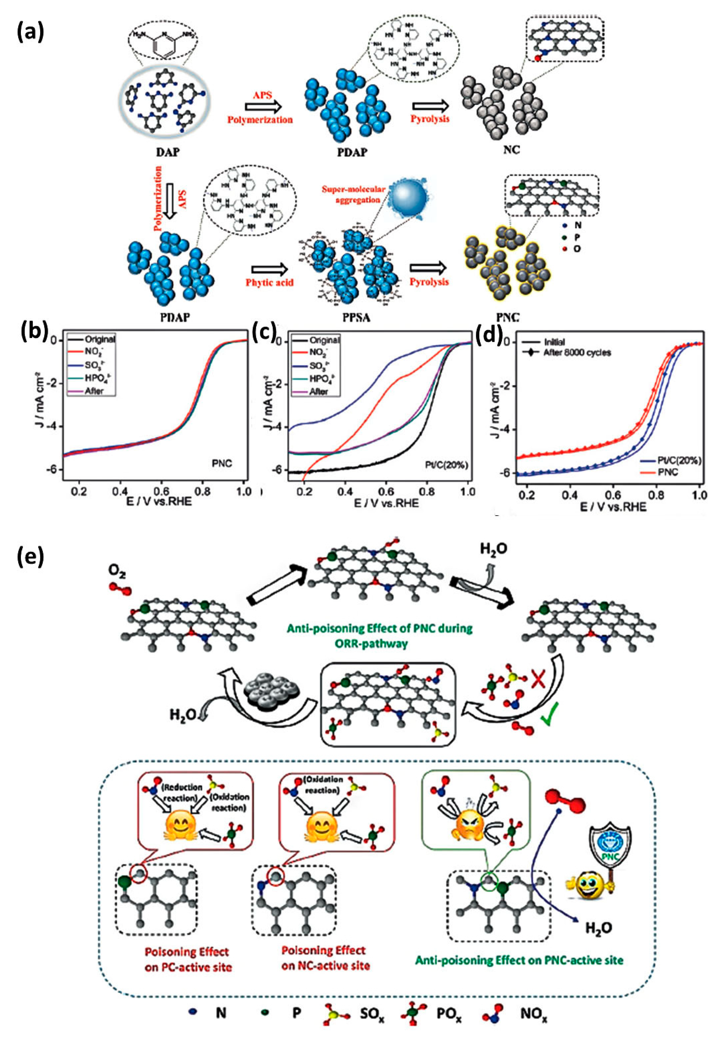
Regarding metal-free catalysts, only a few studies have been published on tolerance to withstand small molecular toxins, which could be a crucial factor for many potential applications. Based on theoretical research the doping of P and N could be promising for the ORR because it can result in highly confined states near the Fermi level [130,131,132]. When compared with N, P is bigger in atomic size and has lower electronegativity, and doped P alters the surrounding electron and spin density of N-doped C via its 3p lone-pair electrons and facilitates the adsorption of oxygen molecules by allowing its valence electrons to migrate towards its unfilled 3d orbitals [93]. This may be advantageous for establishing high tolerance upon small poisonous substances. This concept was experimentally validated by Wei et al. [133], who synthesized a P,N-doped carbon (PNC) material through the pyrolysis of a self-assembled supramolecular precursor (Figure 19a). The resulting metal-free PNC catalyst exhibited not only excellent ORR performance and stability but also, most importantly, a robust anti-poisoning ability. As demonstrated in poisoning tests (Figure 19b–e), the PNC catalyst maintained stable performance in the presence of SOx, NOx, and POx. In stark contrast, control samples of N-doped carbon (NC), P-doped carbon (PC), and even commercial Pt/C all showed significant performance degradation under the same conditions. The authors attributed the high catalytic activity of PNC to the abundance of graphitic edge-defects created by dual doping.
Table 2 summarizes the performance of recently reported NPM advanced electrocatalyst in HT-PEMFCs. This comparative summary highlights several critical trends. A wide range of peak power densities have been reported, from 20 mW cm−2 to an impressive 700 mW cm−2 for a BP-Fe-N-C catalyst, though this required a very high cathode loading of 7.8 mg cm−2. This exemplifies the recurring issue that achieving high performance necessitates thick catalyst layers, which can impede mass transport. More recent advancements, however, showcase a promising path forward. Catalysts on advanced supports like graphene or CNTs (e.g., FeSA-G, FeCu/N-CNTs) and those with P-doping (Fe-NCP) demonstrate excellent power densities (266–357 mW cm−2) and enhanced stability at high operating temperatures. The bimetallic FeCu/N-CNT system is particularly noteworthy for its outstanding durability and unique synergistic interaction with the phosphate electrolyte. The data also underscore the difficulty in making direct comparisons due to variations in test protocols across studies. Nevertheless, the clear progression towards more durable and sophisticated catalyst architectures is encouraging for future development.
Overall, these results provide strong evidence that well-designed metal-free catalysts can effectively address the critical challenge of poison tolerance in HT-PEMFCs. The performance of the PNC catalyst demonstrates a promising pathway for developing next-generation cathodes that are intrinsically durable in chemically demanding operating environments.

3. Challenges and Future Perspectives

Currently, despite a lot of progress in the development of NPM catalysts for HT-PEMFCs, there are still a number of important challenges to overcome. Further development of this technology mainly depends on overcoming these challenges via distinctive scientific methods and rigorous engineering. This section summarizes the main challenges and suggests potential approaches to further study that might lead to a breakthrough.

3.1. Current Challenges in NPM Catalyst Development for HT-PEMFCs

The research scenario for NPM catalysts in HT-PEMFCs is currently characterized by four main challenges:
(1)
Limitation between Activity and Stability: An ongoing and essential problem in the fabrication of M-N-C catalysts is the contrary interaction between the initial activity and stability. The high-temperature pyrolysis process is necessary to synthesize the highly active and graphitic M-Nx sites, often due to carbon support being more sensitive to electrochemical corrosion [135]. On the other hand, the synthesis conditions provide more durable catalysts, but amorphous carbon support might not provide sufficient active sites [130,136]. One of the main objectives of the field is to overcome this limitation in order to produce a catalyst that is both extremely active and extremely durable.
(2)
Mass Transport and Electrode Engineering: As mentioned earlier, thick catalyst layers are required to obtain sufficient performance due to the lower volumetric activity of NPMs in comparison to Pt [137]. This leads to a series of mass transit-related engineering issues. A high thickness and porous layer will severely hinder the transport of oxygen toward the active sites and the outflow of water vapor, resulting in concentration losses and reduction in the power density of fuel cells, particularly under high load [92]. Additionally, regulating PA ionomer diffusion within this thick coating layer is essential, as too little acid leads to inefficient proton conductivity and poor active sites, while a surplus amount of acid (flooding) blocks the pores and stops the diffusion of gas [137,138]. This is an electrode-level technical challenge and equally significant as the synthesis of catalyst materials [139].
(3)
Understanding and Mitigating Degradation in PA: Fe-N-C catalysts have been admired because of their ability to withstand phosphate poisoning, which involves reversibly blocking active sites, although they are not impervious to the general harshness of the HT-PEMFC environment [89]. The corrosive properties of concentrated PA, high electrode potential, and high temperature (160–200 °C) can all speed up basic degradation processes such as carbon support corrosion and dissolution of the active metal centers [140]. The mechanism of degradation is a complicated, interconnected phenomenon in which the PA electrolyte, the Polybenzimidazole (PBI) membrane, and the catalyst all interact with one another and degrade over time [141]. Developing an extensive understanding of these interconnected system-level failure mechanisms requires designing an extremely long-lasting MEA.
(4)
Scalability and Standardization: There is an enormous gap between laboratory-scale innovations and industrial-scale production. A lot of sophisticated synthesis techniques, which produce high-performance catalysts, such as multi-step templating or Chemical Vapor Deposition (CVD), are complicated and might not be commercially scalable [137]. For commercial transformation, developing more straightforward and reliable synthesis methods is essential. At the same time, the absence of widely accepted, standardized processes for MEA development and long-term testing makes it very challenging to consistently evaluate performance data from various research groups and determine which catalyst candidates show the greatest promise for future development [137].

3.2. Innovative Approaches and Future Research Directions

Addressing these complex issues is necessary to achieve a conceptual change from theoretical, experimental approaches to a more logical, system-level approach. The development of the field lies is at the correlation of advancement in the materials science, chemical engineering, and computational science, where the in-depth analysis of failure mechanisms directly impacts the design of new materials and electrodes.
Rational catalyst design for NPM materials benefits greatly from computational modeling and advanced in situ characterization techniques. Because the synthesis of M–N–C catalysts involves a vast array of variables—such as precursors, compositions, and temperatures—it is impractical to rely solely on extensive experimental screening. Instead, sophisticated computational tools, particularly DFT, can be employed to evaluate the stability of potential M–N–C structures in PA environments and to predict their oxygen binding energies [141]. These theoretical insights help narrow down the most promising material candidates and guide experimental efforts more efficiently, significantly accelerating the discovery of optimal catalysts.
At the same time, understanding the true nature of active sites and degradation mechanisms in NPM catalysts for HT-PEMFCs requires advanced in situ and operando characterization methods to observe catalytic activity under real operating conditions. For example, operando electrochemical mass spectrometry can detect volatile decomposition products in real time, providing insights into catalyst degradation pathways, while synchrotron-based X-ray absorption spectroscopy (XAS) enables detailed investigation of metal center coordination and oxidation states under applied potentials [142,143]. Despite these advancements, the field still lacks standardized post-mortem analysis to confirm degradation routes under realistic HT-PEMFC conditions. Techniques such as X-ray Photoelectron Spectroscopy (XPS) for tracking surface functional groups, XAS for probing the local structure of Fe/Co sites, HR-TEM for identifying morphological changes, Mössbauer spectroscopy for differentiating Fe oxidation states, and ICP-MS for quantifying metal leaching are essential tools for understanding failure modes in NPM catalysts. The insights gained from these techniques clarify the fundamental causes of performance loss and provide guidance for the rational redesign of next-generation catalysts.
  • Urgent Need for Standardized Protocols:
We highlight the urgent need for international consensus on testing conditions for HT-PEMFCs, analogous to the standardized protocols developed for LT-PEMFCs by organizations such as DOE, EU Horizon 2020, and IUPAC. Standardization would improve data reproducibility, facilitate cross-laboratory comparisons, and accelerate catalyst development for real-world applications.
  • Proposed Framework for Future Benchmarking:
We propose a tentative benchmarking framework for NPM catalysts in HT-PEMFCs, which includes the following:
(i)
Standard operating window: Temperature = 160–180 °C, pressure = 1 atm, and RH = 0–20%, using doped PBI-type membranes.
(ii)
Electrode architecture: Standardized catalyst loading (e.g., 1.0 ± 0.2 mg/cm2), gas diffusion layer, and ink composition.
(iii)
Electrochemical protocols: Report initial activity via polarization curves and ORR onset potential, and assess stability via 100 h chronoamperometry or accelerated stress tests (ASTs).
(iv)
Post-mortem analysis: Encourage the use of XPS, XAS, and HR-TEM to understand degradation mechanisms.
(v)
Data reporting format: Include both gravimetric and areal performance metrics (mA/mg, mA/cm2), membrane resistance, and cell voltage at defined current densities.

4. Conclusions and Remarks

The search for a clean and sustainable energy system has drawn considerable attention to high-performance energy conversion technologies, among which HT-PEMFCs stand out for their distinct benefits in terms of fuel flexibility and system simplicity. However, the use of expensive and rare PGM catalysts has limited their application. The use of PGM catalysts is even worse in the HT-PEMFC environment due to extreme catalyst poisoning with the PA electrolyte. This review has demonstrated the remarkable progress made in the development of NPM catalysts as a significant solution to this challenge.
The key findings of this comprehensive analysis of M-N-C catalysts, especially those made of iron, is that they have become the apparent leading materials to replace the platinum. They are particularly well-suited for HT-PEMFCs because of their remarkable intrinsic activity for the ORR and, more importantly, their basic robustness to phosphate poisoning. The development of catalysts with high densities of atomically distributed active sites within hierarchically porous structures has been made possible by advancements in synthesis techniques, particularly those that use Metal–Organic Frameworks (MOFs) as self-sacrificing templates. This has resulted in encouraging initial performance in single-cell devices.
Despite all of these impressive achievements, we still face severe challenges to commercialization. Under the severe operating circumstances of an HT-PEMFC, the most significant obstacle in the present NPM catalysts is limited long-term durability. It is necessary to carefully address the interrelated failure mechanisms such as poor mass transport within the unavoidably thick catalyst layers, active site degradation by demetallation and radical attack, and carbon support corrosion. In addition, real-world application requires bridging the gap between complex lab-scale synthesis and scalable, economical manufacturing processes.
The future of NPM catalyst development will be driven by a synergistic integration of advanced computational modelling to guide the identification of materials, advanced operando assessment methods to uncover the true mechanisms of degradation, and novel-electrode engineering to get around mass transport constraints. A particularly interesting approach is the development of innovative composite catalysts, which combine the better stability of corrosion-resi stant substrates such as MXenes and transition metal carbides with the high activity of M-N-C catalysts.

Author Contributions

Writing—original draft and Investigation, N.N.; Investigation and Data curation, B.R.; Writing—review and editing and Methodology, I.E.; Resources and Project administration, H.L.; Supervision and Funding acquisition, H.S. All authors have read and agreed to the published version of the manuscript.

Funding

This work was supported by National Key R&D Program of China (2018YFE0121200) and Priority Academic Program Development (PAPD) of Jiangsu Higher Education Institutions.

Data Availability Statement

Data will be made available upon request.

Conflicts of Interest

The authors declare that they have no conflicts of interest related to the content of this manuscript.

References

  1. Ritchie, H.; Roser, M. CO2 emissions. Our World Data 2020. Available online: https://ourworldindata.org/co2-emissions (accessed on 10 August 2025).
  2. IEA. Global Energy Review 2025; IEA: Paris, France, 2025. [Google Scholar]
  3. Yan, H.; Acquah, S.J.; Zhang, C.; Wang, G.; Huang, S.; Zhang, H.; Zhao, B.; Wu, H. Energy partitioning of greenhouse cucumber based on the application of Penman-Monteith and Bulk Transfer models. Agric. Water Manage. 2019, 217, 201–211. [Google Scholar] [CrossRef]
  4. Khan, K.Y.; Tang, Y.; Cheng, P.; Song, Y.; Li, X.; Lou, J.; Iqbal, B.; Zhao, X.; Hameed, R.; Li, G.; et al. Effects of degradable and non-degradable microplastics and oxytetracycline co-exposure on soil N2O and CO2 emissions. Appl. Soil Ecol. 2024, 197, 105331. [Google Scholar] [CrossRef]
  5. Jiangyi, H.; Fan, W. Design and testing of a small orchard tractor driven by a power battery. Eng. Agríc. 2023, 43, e20220195. [Google Scholar] [CrossRef]
  6. Zhang, H.; Shen, P.K. Advances in the high performance polymer electrolyte membranes for fuel cells. Chem. Soc. Rev. 2012, 41, 2382–2394. [Google Scholar] [CrossRef] [PubMed]
  7. Zhu, Z.; Zeng, L.; Chen, L.; Zou, R.; Cai, Y. Fuzzy Adaptive Energy Management Strategy for a Hybrid Agricultural Tractor Equipped with HMCVT. Agriculture 2022, 12, 1986. [Google Scholar] [CrossRef]
  8. Zhu, Z.; Chai, X.; Xu, L.; Quan, L.; Yuan, C.; Tian, S. Design and performance of a distributed electric drive system for a series hybrid electric combine harvester. Biosystems Eng. 2023, 236, 160–174. [Google Scholar] [CrossRef]
  9. Sheng, B.; Pan, T.; Luo, Y.; Jermsittiparsert, K. System Identification of the PEMFCs based on Balanced Manta-Ray Foraging Optimization algorithm. Energy Reports 2020, 6, 2887–2896. [Google Scholar] [CrossRef]
  10. Haider, R.; Wen, Y.; Ma, Z.-F.; Wilkinson, D.P.; Zhang, L.; Yuan, X.; Song, S.; Zhang, J. High temperature proton exchange membrane fuel cells: Progress in advanced materials and key technologies. Chem. Soc. Rev. 2021, 50, 1138–1187. [Google Scholar] [CrossRef]
  11. Moorthy, S.; Sivasubramanian, G.; Kannaiyan, D.; Deivanayagam, P. Neoteric advancements in polybenzimidazole based polymer electrolytes for high-temperature proton exchange membrane fuel cells-A versatile review. Int. J. Hydrogen Energy 2023, 48, 28103–28118. [Google Scholar] [CrossRef]
  12. Zhang, W.; Jiang, Z.; Lu, Y.; He, Z.; Shao, Z.; Yu, J. Optimization of porous layer structure of high-temperature proton exchange membrane fuel cell based on deep learning and Monte Carlo method. Int. J. Hydrogen Energy 2024, 50, 1004–1019. [Google Scholar] [CrossRef]
  13. Wieser, C. Novel polymer electrolyte membranes for automotive applications–requirements and benefits. Fuel Cells 2004, 4, 245–250. [Google Scholar] [CrossRef]
  14. Ding, X.; Ahmad, W.; Wu, J.; Rong, Y.; Ouyang, Q.; Chen, Q. Bipyridine-mediated fluorescence charge transfer process based on copper ion grafted upconversion nanoparticle platform for ciprofloxacin sensing in aquatic products. Food Chem. 2023, 404, 134761. [Google Scholar] [CrossRef]
  15. Hu, D.; Liu, J.; Yi, F.; Yang, Q.; Zhou, J. Enhancing heat dissipation to improve efficiency of two-stage electric air compressor for fuel cell vehicle. Energy Convers. Manag. 2022, 251, 115007. [Google Scholar] [CrossRef]
  16. Zabed, H.M.; Akter, S.; Yun, J.; Zhang, G.; Zhang, Y.; Qi, X. Biogas from microalgae: Technologies, challenges and opportunities. Renew. Sustain. Energy Rev. 2020, 117, 109503. [Google Scholar] [CrossRef]
  17. Chen, D.; Zou, Y.; Shi, W.; Serbin, S.; You, H. Proton exchange membrane fuel cells using new cathode field designs of multi-inlet shunt intake design. Int. J. Energy Res. 2021, 45, 9948–9960. [Google Scholar] [CrossRef]
  18. Sun, L.; Zheng, B.; Liu, W. Constructing high-throughput and highly adsorptive lithium–sulfur battery separator coatings based on three-dimensional hexagonal star-shaped MOF derivatives. J. Colloid. Interface Sci. 2025, 679, 197–205. [Google Scholar] [CrossRef]
  19. Jiao, K.; Alaefour, I.E.; Li, X. Three-dimensional non-isothermal modeling of carbon monoxide poisoning in high temperature proton exchange membrane fuel cells with phosphoric acid doped polybenzimidazole membranes. Fuel 2011, 90, 568–582. [Google Scholar] [CrossRef]
  20. Lopes, P.P.; Freitas, K.S.; Ticianelli, E.A. CO tolerance of PEMFC anodes: Mechanisms and electrode designs. Electrocatalysis 2010, 1, 200–212. [Google Scholar] [CrossRef]
  21. Nachiappan, N.; Kalaignan, G.P.; Sasikumar, G. Influence of methanol impurity in hydrogen on PEMFC performance. Ionics 2013, 19, 517–522. [Google Scholar] [CrossRef]
  22. Simon Araya, S.; Liso, V.; Cui, X.; Li, N.; Zhu, J.; Sahlin, S.L.; Jensen, S.H.; Nielsen, M.P.; Kær, S.K. A review of the methanol economy: The fuel cell route. Energies 2020, 13, 596. [Google Scholar] [CrossRef]
  23. Profatilova, I.; Jacques, P.-A.; Escribano, S. Evaluation of parameters accelerating the aging of PEMFCs operating under reformate containing carbon monoxide. J. Electrochem. Soc. 2018, 165, F3251. [Google Scholar] [CrossRef]
  24. Dias, V.; Pochet, M.; Contino, F.; Jeanmart, H. Energy and economic costs of chemical storage. Front. Mech. Eng. 2020, 6, 21. [Google Scholar] [CrossRef]
  25. Authayanun, S.; Im-Orb, K.; Arpornwichanop, A. A review of the development of high temperature proton exchange membrane fuel cells. Chin. J. Catal. 2015, 36, 473–483. [Google Scholar] [CrossRef]
  26. Reshetenko, T.V.; Bethune, K.; Rubio, M.A.; Rocheleau, R. Study of low concentration CO poisoning of Pt anode in a proton exchange membrane fuel cell using spatial electrochemical impedance spectroscopy. J. Power Sources 2014, 269, 344–362. [Google Scholar] [CrossRef]
  27. St-Pierre, J. PEMFC contaminant tolerance limit—CO in H2. Electrochim. Acta 2010, 55, 4208–4211. [Google Scholar] [CrossRef]
  28. Wang, Y.; Wu, Q.; Mei, D.; Wang, Y. Development of highly efficient methanol steam reforming system for hydrogen production and supply for a low temperature proton exchange membrane fuel cell. Int. J. Hydrog. Energy 2020, 45, 25317–25327. [Google Scholar] [CrossRef]
  29. Jin, W.; Zhang, Z.; Zhao, S.; Liu, J.; Gao, R.; Jiang, P. Characterization of volatile organic compounds of different pigmented rice after puffing based on gas chromatography-ion migration spectrometry and chemometrics. Food Res. Int. 2023, 169, 112879. [Google Scholar] [CrossRef]
  30. Subianto, S. Recent advances in polybenzimidazole/phosphoric acid membranes for high-temperature fuel cells. Polym. Int. 2014, 63, 1134–1144. [Google Scholar] [CrossRef]
  31. Chandan, A.; Hattenberger, M.; El-Kharouf, A.; Du, S.; Dhir, A.; Self, V.; Pollet, B.G.; Ingram, A.; Bujalski, W. High temperature (HT) polymer electrolyte membrane fuel cells (PEMFC)–A review. J. Power Sources 2013, 231, 264–278. [Google Scholar] [CrossRef]
  32. Shabani, B.; Hafttananian, M.; Khamani, S.; Ramiar, A.; Ranjbar, A.A. Poisoning of proton exchange membrane fuel cells by contaminants and impurities: Review of mechanisms, effects, and mitigation strategies. J. Power Sources 2019, 427, 21–48. [Google Scholar] [CrossRef]
  33. Oono, Y.; Fukuda, T.; Sounai, A.; Hori, M. Influence of operating temperature on cell performance and endurance of high temperature proton exchange membrane fuel cells. J. Power Sources 2010, 195, 1007–1014. [Google Scholar] [CrossRef]
  34. Tse, E.C.M.; Gewirth, A.A. Effect of temperature and pressure on the kinetics of the oxygen reduction reaction. J. Phys. Chem. A 2015, 119, 1246–1255. [Google Scholar] [CrossRef]
  35. Zhang, J.; Aili, D.; Lu, S.; Li, Q.; Jiang, S.P. Advancement toward polymer electrolyte membrane fuel cells at elevated temperatures. Research 2020, 2020, 9089405. [Google Scholar] [CrossRef]
  36. Belgacem, N.; Pauchet, J.; Prat, M. On the current distribution at the channel–rib scale in polymer-electrolyte fuel cells. Int. J. Hydrog. Energy 2018, 43, 5112–5123. [Google Scholar] [CrossRef]
  37. Lv, R.; Huang, X.; Aheto, J.H.; Dai, C.; Tian, X. Research on reaction mechanism of colorimetric sensor array with lead and its application for determination of lead content of fish. J. Food Process Eng. 2019, 42, e13075. [Google Scholar] [CrossRef]
  38. Araya, S.S.; Zhou, F.; Liso, V.; Sahlin, S.L.; Vang, J.R.; Thomas, S.; Gao, X.; Jeppesen, C.; Kær, S.K. A comprehensive review of PBI-based high temperature PEM fuel cells. Int. J. Hydrog. Energy 2016, 41, 21310–21344. [Google Scholar] [CrossRef]
  39. Herdem, M.S.; Sinaki, M.Y.; Farhad, S.; Hamdullahpur, F. An overview of the methanol reforming process: Comparison of fuels, catalysts, reformers, and systems. Int. J. Energy Res. 2019, 43, 5076–5105. [Google Scholar] [CrossRef]
  40. Li, N.; Cui, X.; Zhu, J.; Zhou, M.; Liso, V.; Cinti, G.; Sahlin, S.L.; Araya, S.S. A review of reformed methanol-high temperature proton exchange membrane fuel cell systems. Renew. Sustain. Energy Rev. 2023, 182, 113395. [Google Scholar] [CrossRef]
  41. Xia, X.; Ren, M.; He, W.-S.; Jia, C.; Zhang, X. The preparation of phytosteryl succinyl sucrose esters and improvement of their water solubility and emulsifying properties. Food Chem. 2022, 373, 131501. [Google Scholar] [CrossRef]
  42. Mei, S.; Yang, C.; Song, X.; Wang, T.; Wang, Y.; Geng, Y.; Wang, J.; Su, S. Analysis of the effect of sterilization and storage on the quality of Pinus yunnanensis pollen based on untargeted metabonomics. J. Food Process. Preserv. 2021, 45, e16033. [Google Scholar] [CrossRef]
  43. Bayat, M.; Özalp, M. Effects of leak current density and doping level on energetic, exergetic and ecological performance of a high-temperature PEM fuel cell. Int. J. Hydrog. Energy 2023, 48, 23212–23229. [Google Scholar] [CrossRef]
  44. Xu, H.; Song, Y.; Kunz, H.R.; Fenton, J.M. Effect of elevated temperature and reduced relative humidity on ORR kinetics for PEM fuel cells. J. Electrochem. Soc. 2005, 152, A1828. [Google Scholar] [CrossRef]
  45. Wang, X.; Pan, Y.; Wang, X.; Guo, Y.; Ni, C.; Wu, J.; Hao, C. High performance hybrid supercapacitors assembled with multi-cavity nickel cobalt sulfide hollow microspheres as cathode and porous typha-derived carbon as anode. Ind. Crops Prod. 2022, 189, 115863. [Google Scholar] [CrossRef]
  46. Oshchepkov, A.G.; Bonnefont, A.; Parmon, V.N.; Savinova, E.R. On the effect of temperature and surface oxidation on the kinetics of hydrogen electrode reactions on nickel in alkaline media. Electrochim. Acta 2018, 269, 111–118. [Google Scholar] [CrossRef]
  47. Zhao, G.; Chen, J.; Sun, W.; Pan, H. Non-platinum group metal electrocatalysts toward efficient hydrogen oxidation reaction. Adv. Funct. Mater. 2021, 31, 2010633. [Google Scholar] [CrossRef]
  48. Liang, J.; Li, H.; Chen, L.; Ren, M.; Fakayode, O.A.; Han, J.; Zhou, C. Efficient hydrogen evolution reaction performance using lignin-assisted chestnut shell carbon-loaded molybdenum disulfide. Ind. Crops Prod. 2023, 193, 116214. [Google Scholar] [CrossRef]
  49. Zhang, L.; Cai, J.; Chen, Y.; Huang, J. Modelling electrocatalytic reactions with a concerted treatment of multistep electron transfer kinetics and local reaction conditions. J. Phys. Condens. Matter 2021, 33, 504002. [Google Scholar] [CrossRef] [PubMed]
  50. Wu, Q.; Zhong, Y.; Chen, R.; Ling, G.; Wang, X.; Shen, Y.; Hao, C. Cu-Ag-C@Ni3S4 with core shell structure and rose derived carbon electrode materials: An environmentally friendly supercapacitor with high energy and power density. Ind. Crops Prod. 2024, 222, 119676. [Google Scholar] [CrossRef]
  51. Kuzmin, A.V.; Shainyan, B.A. Mechanisms of catalytic electrochemical reactions of oxygen reduction (ORR) and carbon dioxide reduction (CO2RR). Russ. Chem. Rev. 2023, 92, 5085. [Google Scholar] [CrossRef]
  52. Yang, Y.; Peltier, C.R.; Zeng, R.; Schimmenti, R.; Li, Q.; Huang, X.; Yan, Z.; Potsi, G.; Selhorst, R.; Lu, X. Electrocatalysis in alkaline media and alkaline membrane-based energy technologies. Chem. Rev. 2022, 122, 6117–6321. [Google Scholar] [CrossRef]
  53. Yang, F.; Liao, L.-w.; Li, M.-f.; Mei, D.; Chen, Y.-x. Kinetics study on O2 adsorption OHad desorption at Pt(111), its implication to oxygen reduction reaction kinetics. Chin. J. Chem. Phys. 2014, 27, 479–484. [Google Scholar] [CrossRef]
  54. Ji, Q.; Yu, X.; Chen, L.; Yarley, O.P.N.; Zhou, C. Facile preparation of sugarcane bagasse-derived carbon supported MoS2 nanosheets for hydrogen evolution reaction. Ind. Crops Prod. 2021, 172, 114064. [Google Scholar] [CrossRef]
  55. Unnikrishnan, A.; Rajalakshmi, N.; Janardhanan, V.M. Kinetics of electrochemical charge transfer in HT-PEM fuel cells. Electrochim. Acta 2019, 293, 128–140. [Google Scholar] [CrossRef]
  56. Hooshyari, K.; Amini Horri, B.; Abdoli, H.; Fallah Vostakola, M.; Kakavand, P.; Salarizadeh, P. A review of recent developments and advanced applications of high-temperature polymer electrolyte membranes for PEM fuel cells. Energies 2021, 14, 5440. [Google Scholar] [CrossRef]
  57. Kerr, R.; García, H.R.; Rastedt, M.; Wagner, P.; Alfaro, S.M.; Romero, M.T.; Terkelsen, C.; Steenberg, T.; Hjuler, H.A. Lifetime and degradation of high temperature PEM membrane electrode assemblies. Int. J. Hydrogen Energy 2015, 40, 16860–16866. [Google Scholar] [CrossRef]
  58. Yang, Z.; Yu, X.; Zhang, Y.; Xu, G. Remarkably durable platinum cluster supported on multi-walled carbon nanotubes with high performance in an anhydrous polymer electrolyte fuel cell. RSC Adv. 2016, 6, 108158–108163. [Google Scholar] [CrossRef]
  59. Borup, R.; Meyers, J.; Pivovar, B.; Kim, Y.S.; Mukundan, R.; Garland, N.; Myers, D.; Wilson, M.; Garzon, F.; Wood, D. Scientific aspects of polymer electrolyte fuel cell durability and degradation. Chem. Rev. 2007, 107, 3904–3951. [Google Scholar] [CrossRef] [PubMed]
  60. Yousfi-Steiner, N.; Moçotéguy, P.; Candusso, D.; Hissel, D. A review on polymer electrolyte membrane fuel cell catalyst degradation and starvation issues: Causes, consequences and diagnostic for mitigation. J. Power Sources 2009, 194, 130–145. [Google Scholar] [CrossRef]
  61. Honji, A.; Mori, T.; Tamura, K.; Hishinuma, Y. Agglomeration of platinum particles supported on carbon in phosphoric acid. J. Electrochem. Soc. 1988, 135, 355. [Google Scholar] [CrossRef]
  62. Tseung, A.C.C.; Dhara, S.C. Loss of surface area by platinum and supported platinum black electrocatalyst. Electrochim. Acta 1975, 20, 681–683. [Google Scholar] [CrossRef]
  63. Watanabe, M.; Tsurumi, K.; Mizukami, T.; Nakamura, T.; Stonehart, P. Activity and stability of ordered and disordered Co-Pt alloys for phosphoric acid fuel cells. J. Electrochem. Soc. 1994, 141, 2659. [Google Scholar] [CrossRef]
  64. Berejnov, V.; Martin, Z.; West, M.; Kundu, S.; Bessarabov, D.; Stumper, J.; Susac, D.; Hitchcock, A.P. Probing platinum degradation in polymer electrolyte membrane fuel cells by synchrotron X-ray microscopy. Phys. Chem. Chem. Phys. 2012, 14, 4835–4843. [Google Scholar] [CrossRef]
  65. Ascarelli, P.; Contini, V.; Giorgi, R. Formation process of nanocrystalline materials from x-ray diffraction profile analysis: Application to platinum catalysts. J. Appl. Phys. 2002, 91, 4556–4561. [Google Scholar] [CrossRef]
  66. Zhang, J. PEM Fuel Cell Electrocatalysts and Catalyst Layers: Fundamentals and Applications; Springer Science & Business Media: Berlin/Heidelberg, Germany, 2008. [Google Scholar]
  67. Yoda, T.; Uchida, H.; Watanabe, M. Effects of operating potential and temperature on degradation of electrocatalyst layer for PEFCs. Electrochim. Acta 2007, 52, 5997–6005. [Google Scholar] [CrossRef]
  68. Nguyen, H.L.; Han, J.; Nguyen, X.L.; Yu, S.; Goo, Y.-M.; Le, D.D. Review of the durability of polymer electrolyte membrane fuel cell in long-term operation: Main influencing parameters and testing protocols. Energies 2021, 14, 4048. [Google Scholar] [CrossRef]
  69. Borup, R.L.; Kusoglu, A.; Neyerlin, K.C.; Mukundan, R.; Ahluwalia, R.K.; Cullen, D.A.; More, K.L.; Weber, A.Z.; Myers, D.J. Recent developments in catalyst-related PEM fuel cell durability. Curr. Opin. Electrochem. 2020, 21, 192–200. [Google Scholar] [CrossRef]
  70. Kaserer, S.; Caldwell, K.M.; Ramaker, D.E.; Roth, C. Analyzing the influence of H3PO4 as catalyst poison in high temperature PEM fuel cells using in-operando X-ray absorption spectroscopy. J. Phys. Chem. C 2013, 117, 6210–6217. [Google Scholar] [CrossRef]
  71. He, Q.; Yang, X.; Chen, W.; Mukerjee, S.; Koel, B.; Chen, S. Influence of phosphate anion adsorption on the kinetics of oxygen electroreduction on low index Pt (hkl) single crystals. Phys. Chem. Chem. Phys. 2010, 12, 12544–12555. [Google Scholar] [CrossRef]
  72. Caldwell, K.M.; Kaserer, S.; Roth, C.; Ramaker, D.E. Following Adsorbate Coverage on Anodes of High-Temperature Polymer Electrolyte Membrane Fuel Cells in the Presence of CO and H2O by using In Operando X-ray Absorption Spectroscopy. ChemElectroChem 2015, 2, 1502–1509. [Google Scholar] [CrossRef]
  73. Liu, Z.; Wang, L.; Liu, P.; Zhao, K.; Ye, S.; Liang, G. Rapid, ultrasensitive and non-enzyme electrochemiluminescence detection of hydrogen peroxide in food based on the ssDNA/g-C3N4 nanosheets hybrid. Food Chem. 2021, 357, 129753. [Google Scholar] [CrossRef] [PubMed]
  74. Dai, Y.; Peng, W.; Ji, Y.; Wei, J.; Che, J.; Huang, Y.; Huang, W.; Yang, W.; Xu, W. A self-powered photoelectrochemical aptasensor using 3D-carbon nitride and carbon-based metal-organic frameworks for high-sensitivity detection of tetracycline in milk and water. J. Food Sci. 2024, 89, 8022–8035. [Google Scholar] [CrossRef] [PubMed]
  75. Liu, H.; Li, P.; Zhang, T.; Zhu, Y.; Qiu, F. Fabrication of recyclable magnetic double-base aerogel with waste bioresource bagasse as the source of fiber for the enhanced removal of chromium ions from aqueous solution. Food Bioprod. Process. 2020, 119, 257–267. [Google Scholar] [CrossRef]
  76. Meier, J.C.; Galeano, C.; Katsounaros, I.; Witte, J.; Bongard, H.J.; Topalov, A.A.; Baldizzone, C.; Mezzavilla, S.; Schüth, F.; Mayrhofer, K.J.J. Design criteria for stable Pt/C fuel cell catalysts. Beilstein J. Nanotech. 2014, 5, 44–67. [Google Scholar] [CrossRef]
  77. Buschermöhle, J.G.; Müller-Hülstede, J.; Schmies, H.; Schonvogel, D.; Zierdt, T.; Lucka, R.; Renz, F.; Wagner, P.; Wark, M. Fe–Sn–N–C Catalysts: Advancing Oxygen Reduction Reaction Performance. ACS Catal. 2025, 15, 4477–4488. [Google Scholar] [CrossRef]
  78. Zucconi, A.; Hack, J.; Stocker, R.; Suter, T.A.M.; Rettie, A.J.E.; Brett, D.J.L. Challenges and opportunities for characterisation of high-temperature polymer electrolyte membrane fuel cells: A review. J. Mater. Chem. A 2024, 12, 8014–8064. [Google Scholar] [CrossRef]
  79. Li, Q.; Wu, G.; Cullen, D.A.; More, K.L.; Mack, N.H.; Chung, H.T.; Zelenay, P. Phosphate-tolerant oxygen reduction catalysts. ACS Catal. 2014, 4, 3193–3200. [Google Scholar] [CrossRef]
  80. Wang, J.; Ahmad, W.; Mehedi Hassan, M.; Zareef, M.; Viswadevarayalu, A.; Arslan, M.; Li, H.; Chen, Q. Landing microextraction sediment phase onto surface enhanced Raman scattering to enhance sensitivity and selectivity for chromium speciation in food and environmental samples. Food Chem. 2020, 323, 126812. [Google Scholar] [CrossRef]
  81. Guo, Z.; Chen, P.; Yosri, N.; Chen, Q.; Elseedi, H.R.; Zou, X.; Yang, H. Detection of Heavy Metals in Food and Agricultural Products by Surface-enhanced Raman Spectroscopy. Food Rev. Int. 2023, 39, 1440–1461. [Google Scholar] [CrossRef]
  82. Hu, Y.; Jensen, J.O.; Zhang, W.; Martin, S.; Chenitz, R.; Pan, C.; Xing, W.; Bjerrum, N.J.; Li, Q. Fe3C-based oxygen reduction catalysts: Synthesis, hollow spherical structures and applications in fuel cells. J. Mater. Chem. A 2015, 3, 1752–1760. [Google Scholar] [CrossRef]
  83. Mamtani, K.; Jain, D.; Zemlyanov, D.; Celik, G.; Luthman, J.; Renkes, G.; Co, A.C.; Ozkan, U.S. Probing the oxygen reduction reaction active sites over nitrogen-doped carbon nanostructures (CN x) in acidic media using phosphate anion. ACS Catal. 2016, 6, 7249–7259. [Google Scholar] [CrossRef]
  84. Holst-Olesen, K.; Reda, M.; Hansen, H.A.; Vegge, T.; Arenz, M. Enhanced oxygen reduction activity by selective anion adsorption on non-precious-metal catalysts. ACS Catal. 2018, 8, 7104–7112. [Google Scholar] [CrossRef]
  85. Peng, L.; Zhu, A.; Ahmad, W.; Adade, S.Y.-S.S.; Chen, Q.; Wei, W.; Chen, X.; Wei, J.; Jiao, T.; Chen, Q. A three-channel biosensor based on stimuli-responsive catalytic activity of the Fe3O4@Cu for on-site detection of tetrodotoxin in fish. Food Chem. 2024, 460, 140566. [Google Scholar] [CrossRef]
  86. Wang, L.; Huang, X.; Wang, C.; Tian, X.; Chang, X.; Ren, Y.; Yu, S. Applications of surface functionalized Fe3O4 NPs-based detection methods in food safety. Food Chem. 2021, 342, 128343. [Google Scholar] [CrossRef] [PubMed]
  87. Zhang, C.; Shi, X.; Yu, F.; Quan, Y. Preparation of dummy molecularly imprinted polymers based on dextran-modified magnetic nanoparticles Fe3O4 for the selective detection of acrylamide in potato chips. Food Chem. 2020, 317, 126431. [Google Scholar] [CrossRef]
  88. Ma, S.; Pan Lg You, T.; Wang, K. g-C3N4/Fe3O4 Nanocomposites as Adsorbents Analyzed by UPLC-MS/MS for Highly Sensitive Simultaneous Determination of 27 Mycotoxins in Maize: Aiming at Increasing Purification Efficiency and Reducing Time. J. Agric. Food. Chem. 2021, 69, 4874–4882. [Google Scholar] [CrossRef]
  89. Strickland, K.; Pavlicek, R.; Miner, E.; Jia, Q.; Zoller, I.; Ghoshal, S.; Liang, W.; Mukerjee, S. Anion resistant oxygen reduction electrocatalyst in phosphoric acid fuel cell. ACS Catal. 2018, 8, 3833–3843. [Google Scholar] [CrossRef]
  90. Razmjooei, F.; Yu, J.-H.; Lee, H.-Y.; Lee, B.-J.; Singh, K.P.; Kang, T.-H.; Kim, H.-J.; Yu, J.-S. Single-atom iron-based electrocatalysts for high-temperature polymer electrolyte membrane fuel cell: Organometallic precursor and pore texture tailoring. ACS Appl. Energy Mater. 2020, 3, 11164–11176. [Google Scholar] [CrossRef]
  91. Jain, D.; Gustin, V.; Basu, D.; Gunduz, S.; Deka, D.J.; Co, A.C.; Ozkan, U.S. Phosphate tolerance of nitrogen-coordinated-iron-carbon (FeNC) catalysts for oxygen reduction reaction: A size-related hindrance effect. J. Catal. 2020, 390, 150–160. [Google Scholar] [CrossRef]
  92. Müller-Hülstede, J.; Zierdt, T.; Schmies, H.; Schonvogel, D.; Meyer, Q.; Zhao, C.; Wagner, P.; Wark, M. Implementation of different Fe–N–C catalysts in high temperature proton exchange membrane fuel cells–effect of catalyst and catalyst layer on performance. J. Power Sources 2022, 537, 231529. [Google Scholar] [CrossRef]
  93. Yang, X.; Huang, Z.; Du, L.; Li, Q.; Ye, S. Active Sites and Stability Study of Fe/N/C Catalyst in PEMFCs: A Decade of Stunning Progress and the Remaining Challenges. ACS Catal. 2024, 14, 15471–15488. [Google Scholar] [CrossRef]
  94. Hu, Y.; Jensen, J.O.; Pan, C.; Cleemann, L.N.; Shypunov, I.; Li, Q. Immunity of the Fe-NC catalysts to electrolyte adsorption: Phosphate but not perchloric anions. Appl. Catal. B 2018, 234, 357–364. [Google Scholar] [CrossRef]
  95. Gokhale, R.; Asset, T.; Qian, G.; Serov, A.; Artyushkova, K.; Benicewicz, B.C.; Atanassov, P. Implementing PGM-free electrocatalysts in high-temperature polymer electrolyte membrane fuel cells. Electrochem. Commun. 2018, 93, 91–94. [Google Scholar] [CrossRef]
  96. Müller-Hülstede, J.; Schmies, H.; Schonvogel, D.; Meyer, Q.; Nie, Y.; Zhao, C.; Wagner, P.; Wark, M. What determines the stability of Fe-NC catalysts in HT-PEMFCs? Int. J. Hydrog. Energy 2024, 50, 921–930. [Google Scholar] [CrossRef]
  97. Byeon, A.; Lee, K.J.; Lee, M.J.; Lee, J.S.; Lee, I.H.; Park, H.Y.; Lee, S.Y.; Yoo, S.J.; Jang, J.H.; Kim, H.J. Effect of Catalyst Pore Size on the Performance of Non-Precious Fe/N/C-Based Electrocatalysts for High-Temperature Polymer Electrolyte Membrane Fuel Cells. ChemElectroChem 2018, 5, 1805–1810. [Google Scholar] [CrossRef]
  98. Bevilacqua, N.; Asset, T.; Schmid, M.A.; Markötter, H.; Manke, I.; Atanassov, P.; Zeis, R. Impact of catalyst layer morphology on the operation of high temperature PEM fuel cells. J. Power Sources Adv. 2021, 7, 100042. [Google Scholar] [CrossRef]
  99. Li, Y.; Luo, S.; Sun, L.; Kong, D.; Sheng, J.; Wang, K.; Dong, C. A Green, Simple, and Rapid Detection for Amaranth in Candy Samples Based on the Fluorescence Quenching of Nitrogen-Doped Graphene Quantum Dots. Food Anal. Methods 2019, 12, 1658–1665. [Google Scholar] [CrossRef]
  100. Li, W.; Hu, X.; Li, Q.; Shi, Y.; Zhai, X.; Xu, Y.; Li, Z.; Huang, X.; Wang, X.; Shi, J.; et al. Copper nanoclusters @ nitrogen-doped carbon quantum dots-based ratiometric fluorescence probe for lead (II) ions detection in porphyra. Food Chem. 2020, 320, 126623. [Google Scholar] [CrossRef] [PubMed]
  101. Najam, T.; Shah, S.S.A.; Ding, W.; Wei, Z. Role of P-doping in antipoisoning: Efficient MOF-derived 3D hierarchical architectures for the oxygen reduction reaction. J. Phys. Chem. C 2019, 123, 16796–16803. [Google Scholar] [CrossRef]
  102. Yang, W.; Liu, C.; Zhang, B.; Wu, C.; Cao, Y.; Huang, W.; Xu, W. Construction of a Nitrogen-Doped Carbon Quantum Dot Fluorescent Molecularly Imprinted Sensor for Ultra-Sensitive Detection of Sulfadiazine in Pork Samples. Food Anal. Methods 2024, 17, 1689–1701. [Google Scholar] [CrossRef]
  103. Hu, X.; Zhang, X.; Li, Y.; Shi, J.; Huang, X.; Li, Z.; Zhang, J.; Li, W.; Xu, Y.; Zou, X. Easy-to-Use Visual Sensing System for Milk Freshness, Sensitized with Acidity-Responsive N-Doped Carbon Quantum Dots. Foods 2022, 11, 1855. [Google Scholar] [CrossRef]
  104. Jin, X.; Li, Y.; Sun, H.; Gao, X.; Li, J.; Lü, Z.; Liu, W.; Sun, X. Phosphorus induced activity-enhancement of Fe-NC catalysts for high temperature polymer electrolyte membrane fuel cells. Nano Res. 2023, 16, 6531–6536. [Google Scholar] [CrossRef]
  105. Gong, L.; Zhang, H.; Wang, Y.; Luo, E.; Li, K.; Gao, L.; Wang, Y.; Wu, Z.; Jin, Z.; Ge, J. Bridge bonded oxygen ligands between approximated FeN4 sites confer catalysts with high ORR performance. Angew. Chem. Int. Ed. 2020, 132, 14027–14032. [Google Scholar] [CrossRef]
  106. Jing, Y.; Cheng, Y.; Wang, L.; Liu, Y.; Yu, B.; Yang, C. MOF-derived Co, Fe, and Ni co-doped N-enriched hollow carbon as efficient electrocatalyst for oxygen reduction reaction. Chem. Eng. J. 2020, 397, 125539. [Google Scholar] [CrossRef]
  107. Brea, C.; Hu, G. Dual-Atom Catalysts for the Oxygen Reduction Reaction: Unraveling Atomic Structures under Reaction Conditions. J. Am. Chem. Soc. 2025, 147, 19210–19216. [Google Scholar] [CrossRef] [PubMed]
  108. Wang, J.; Huang, Z.; Liu, W.; Chang, C.; Tang, H.; Li, Z.; Chen, W.; Jia, C.; Yao, T.; Wei, S. Design of N-coordinated dual-metal sites: A stable and active Pt-free catalyst for acidic oxygen reduction reaction. J. Am. Chem. Soc. 2017, 139, 17281–17284. [Google Scholar] [CrossRef]
  109. Wang, J.; Liu, W.; Luo, G.; Li, Z.; Zhao, C.; Zhang, H.; Zhu, M.; Xu, Q.; Wang, X.; Zhao, C. Synergistic effect of well-defined dual sites boosting the oxygen reduction reaction. Energy Environ. Sci. 2018, 11, 3375–3379. [Google Scholar] [CrossRef]
  110. Xiao, M.; Chen, Y.; Zhu, J.; Zhang, H.; Zhao, X.; Gao, L.; Wang, X.; Zhao, J.; Ge, J.; Jiang, Z. Climbing the apex of the ORR volcano plot via binuclear site construction: Electronic and geometric engineering. J. Am. Chem. Soc. 2019, 141, 17763–17770. [Google Scholar] [CrossRef]
  111. Kattel, S.; Wang, G. A density functional theory study of oxygen reduction reaction on Me–N4 (Me = Fe, Co, or Ni) clusters between graphitic pores. J. Mater. Chem. A 2013, 1, 10790–10797. [Google Scholar] [CrossRef]
  112. Liu, J.; Fan, C.; Liu, G.; Jiang, L. MOF-derived dual metal (Fe, Ni)–nitrogen–doped carbon for synergistically enhanced oxygen reduction reaction. Appl. Surf. Sci. 2021, 538, 148017. [Google Scholar] [CrossRef]
  113. Ameena, S.; Rajesh, N.; Anjum, S.M.; Khadri, H.; Riazunnisa, K.; Mohammed, A.; Kari, Z.A. Antioxidant, Antibacterial, and Anti-diabetic Activity of Green Synthesized Copper Nanoparticles of Cocculus hirsutus (Menispermaceae). Appl. Biochem. Biotechnol. 2022, 194, 4424–4438. [Google Scholar] [CrossRef]
  114. Qin, C.; Guo, W.; Liu, Y.; Liu, Z.; Qiu, J.; Peng, J. A Novel Electrochemical Sensor Based on Graphene Oxide Decorated with Silver Nanoparticles–Molecular Imprinted Polymers for Determination of Sunset Yellow in Soft Drinks. Food Anal. Methods 2017, 10, 2293–2301. [Google Scholar] [CrossRef]
  115. Liu, Y.; Jing, Z.; Zhang, T.; Chen, Q.; Qiu, F.; Peng, Y.; Tang, S. Fabrication of functional biomass carbon aerogels derived from sisal fibers for application in selenium extraction. Food Bioprod. Process. 2018, 111, 93–103. [Google Scholar] [CrossRef]
  116. Yuan, J.; Zhu, Y.; Wang, J.; Gan, L.; He, M.; Zhang, T.; Li, P.; Qiu, F. Preparation and application of Mg–Al composite oxide/coconut shell carbon fiber for effective removal of phosphorus from domestic sewage. Food Bioprod. Process. 2021, 126, 293–304. [Google Scholar] [CrossRef]
  117. Shen, L.Q.; Zhou, X.; Zhang, C.X.; Yin, H.B.; Wang, A.L.; Wang, C.T. Functional characterization of bimetallic CuPdx nanoparticles in hydrothermal conversion of glycerol to lactic acid. J. Food Biochem. 2019, 43, e12931. [Google Scholar] [CrossRef] [PubMed]
  118. Zhang, T.; Zhao, B.; Chen, Q.; Peng, X.; Yang, D.; Qiu, F. Layered double hydroxide functionalized biomass carbon fiber for highly efficient and recyclable fluoride adsorption. Appl. Biol. Chem. 2019, 62, 12. [Google Scholar] [CrossRef]
  119. Bu, Q.; Chen, K.; Morgan, H.M.; Liang, J.; Zhang, X.; Yan, L.; Mao, H. Thermal Behavior and Kinetic Study of the Effects of Zinc-Modified Biochar Catalyst on Lignin and Low-Density Polyethylene (LDPE) Co-Pyrolysis. Trans. ASABE 2018, 61, 1783–1793. [Google Scholar] [CrossRef]
  120. Cheng, Y.; He, S.; Lu, S.; Veder, J.P.; Johannessen, B.; Thomsen, L.; Saunders, M.; Becker, T.; De Marco, R.; Li, Q.; et al. Iron single atoms on graphene as nonprecious metal catalysts for high-temperature polymer electrolyte membrane fuel cells. Adv. Sci. 2019, 6, 1802066. [Google Scholar] [CrossRef]
  121. Cheng, Y.; Zhang, J.; Wu, X.; Tang, C.; Yang, S.-z.; Su, P.; Thomsen, L.; Zhao, F.; Lu, S.; Liu, J. A template-free method to synthesis high density iron single atoms anchored on carbon nanotubes for high temperature polymer electrolyte membrane fuel cells. Nano Energy 2021, 80, 105534. [Google Scholar] [CrossRef]
  122. Wang, M.; Lu, S.; Wu, X.; Veder, J.-P.; Johannessen, B.; Thomsen, L.; Zhang, J.; Yang, S.-z.; Jiang, S.P. First demonstration of phosphate enhanced atomically dispersed bimetallic FeCu catalysts as Pt-free cathodes for high temperature phosphoric acid doped polybenzimidazole fuel cells. Appl. Catal. B 2021, 284, 119717. [Google Scholar]
  123. Chenitz, R.; Kramm, U.I.; Lefèvre, M.; Glibin, V.; Zhang, G.; Sun, S.; Dodelet, J.-P. A specific demetalation of Fe–N4 catalytic sites in the micropores of NC_Ar + NH3 is at the origin of the initial activity loss of the highly active Fe/N/C catalyst used for the reduction of oxygen in PEM fuel cells. Energy Environ. Sci. 2018, 11, 365–382. [Google Scholar] [CrossRef]
  124. Zhang, T.; Yuan, D.; Guo, Q.; Qiu, F.; Yang, D.; Ou, Z. Preparation of a renewable biomass carbon aerogel reinforced with sisal for oil spillage clean-up: Inspired by green leaves to green Tofu. Food Bioprod. Process. 2019, 114, 154–162. [Google Scholar] [CrossRef]
  125. Hu, Z.; Wang, Y.; Fang, Z.; Shi, G.; Lou, L.; Ren, K.; Cai, Q. Italian ryegrass–rice rotation system for biomass production and cadmium removal from contaminated paddy fields. J. Soils Sediments 2020, 20, 874–882. [Google Scholar] [CrossRef]
  126. Choi, C.H.; Baldizzone, C.; Grote, J.P.; Schuppert, A.K.; Jaouen, F.; Mayrhofer, K.J.J. Stability of Fe-N-C catalysts in acidic medium studied by operando spectroscopy. Angew. Chem. Int. Ed. 2015, 54, 12753–12757. [Google Scholar] [CrossRef]
  127. Kinumoto, T.; Inaba, M.; Nakayama, Y.; Ogata, K.; Umebayashi, R.; Tasaka, A.; Iriyama, Y.; Abe, T.; Ogumi, Z. Durability of perfluorinated ionomer membrane against hydrogen peroxide. J. Power Sources 2006, 158, 1222–1228. [Google Scholar] [CrossRef]
  128. Zhang, Q.; Mamtani, K.; Jain, D.; Ozkan, U.; Asthagiri, A. CO poisoning effects on FeNC and CN x ORR catalysts: A combined experimental–computational study. J. Phys. Chem. C 2016, 120, 15173–15184. [Google Scholar] [CrossRef]
  129. Zhang, J.; Dai, L. Nitrogen, phosphorus, and fluorine tri-doped graphene as a multifunctional catalyst for self-powered electrochemical water splitting. Angew. Chem. Int. Ed. 2016, 128, 13490–13494. [Google Scholar] [CrossRef]
  130. Wang, D.-W.; Su, D. Heterogeneous nanocarbon materials for oxygen reduction reaction. Energy Environ. Sci. 2014, 7, 576–591. [Google Scholar] [CrossRef]
  131. Liu, H.; Li, P.; Qiu, F.; Zhang, T.; Xu, J. Controllable preparation of FeOOH/CuO@WBC composite based on water bamboo cellulose applied for enhanced arsenic removal. Food Bioprod. Process. 2020, 123, 177–187. [Google Scholar] [CrossRef]
  132. Shao, Z.; Xing, C.; Xue, M.; Fang, Y.; Li, P. Selective removal of Pb(II) from yellow rice wine using magnetic carbon-based adsorbent. J. Sci. Food Agric. 2023, 103, 6929–6939. [Google Scholar] [CrossRef] [PubMed]
  133. Najam, T.; Shah, S.S.A.; Ding, W.; Jiang, J.; Jia, L.; Yao, W.; Li, L.; Wei, Z. An efficient anti-poisoning catalyst against SOx, NOx, and POx: P, N-doped carbon for oxygen reduction in acidic media. Angew. Chem. Int. Ed. 2018, 130, 15321–15326. [Google Scholar] [CrossRef]
  134. Mooste, M.; Müller-Hülstede, J.; Schonvogel, D.; Zierdt, T.; Buschermöhle, J.; Fuhrmann, K.; Wilhelm, M.; Wagner, P.; Friedrich, K.A. Binary transition metal and ZIF-8 functionalised polymer-derived ceramic catalysts for high temperature PEM fuel cell cathode. Electrochim. Acta 2025, 514, 145620. [Google Scholar] [CrossRef]
  135. Elshamy, A.I.; Mohamed, T.A.; Essa, A.F.; Abd-El Gawad, A.M.; Alqahtani, A.S.; Shahat, A.A.; Yoneyama, T.; Farrag, A.R.H.; Noji, M.; El-Seedi, H.R.; et al. Recent Advances in Kaempferia Phytochemistry and Biological Activity: A Comprehensive Review. Nutrients 2019, 11, 2396. [Google Scholar] [CrossRef] [PubMed]
  136. Kumar, K.; Dubau, L.; Jaouen, F.; Maillard, F. Review on the degradation mechanisms of metal-NC catalysts for the oxygen reduction reaction in acid electrolyte: Current understanding and mitigation approaches. Chem. Rev. 2023, 123, 9265–9326. [Google Scholar] [CrossRef]
  137. Zierdt, T.; Müller-Hülstede, J.; Schmies, H.; Schonvogel, D.; Wagner, P.; Friedrich, K.A. Effect of polytetrafluorethylene content in Fe-N-C-based catalyst layers of gas diffusion electrodes for HT-PEM fuel cell applications. ChemElectroChem 2024, 11, e202300583. [Google Scholar] [CrossRef]
  138. Han, J.; Feng, H.; Wu, J.; Li, Y.; Zhou, Y.; Wang, L.; Luo, P.; Wang, Y. Construction of Multienzyme Co-immobilized Hybrid Nanoflowers for an Efficient Conversion of Cellulose into Glucose in a Cascade Reaction. J. Agric. Food. Chem. 2021, 69, 7910–7921. [Google Scholar] [CrossRef] [PubMed]
  139. Martinaiou, I.; Daletou, M.K. Enhancing Electrode Efficiency in Proton Exchange Membrane Fuel Cells with PGM-Free Catalysts: A Mini Review. Energies 2024, 17, 3443. [Google Scholar] [CrossRef]
  140. Chowdury, M.S.K.; Park, Y.; Park, S.B.; Park, Y.-i. Degradation Mechanisms Long-Term durability Challenges mitigation methods for proton exchange membranes membrane electrode assemblies with Pt/Celectrocatalysts in Low-Temperature High-Temperature fuel Cells: Acomprehensive review. J. Electroanal. Chem. 2024, 975, 118712. [Google Scholar] [CrossRef]
  141. Lim, K.H.; Matanovic, I.; Maurya, S.; Kim, Y.; De Castro, E.S.; Jang, J.-H.; Park, H.; Kim, Y.S. High temperature polymer electrolyte membrane fuel cells with high phosphoric acid retention. ACS Energy Lett. 2022, 8, 529–536. [Google Scholar] [CrossRef]
  142. Tellez-Cruz, M.M.; Escorihuela, J.; Solorza-Feria, O.; Compañ, V. Proton exchange membrane fuel cells (PEMFCs): Advances and challenges. Polymers 2021, 13, 3064. [Google Scholar] [CrossRef]
  143. Hossen, M.M.; Artyushkova, K.; Atanassov, P.; Serov, A. Synthesis and characterization of high performing Fe-N-C catalyst for oxygen reduction reaction (ORR) in Alkaline Exchange Membrane Fuel Cells. J. Power Sources 2018, 375, 214–221. [Google Scholar] [CrossRef]
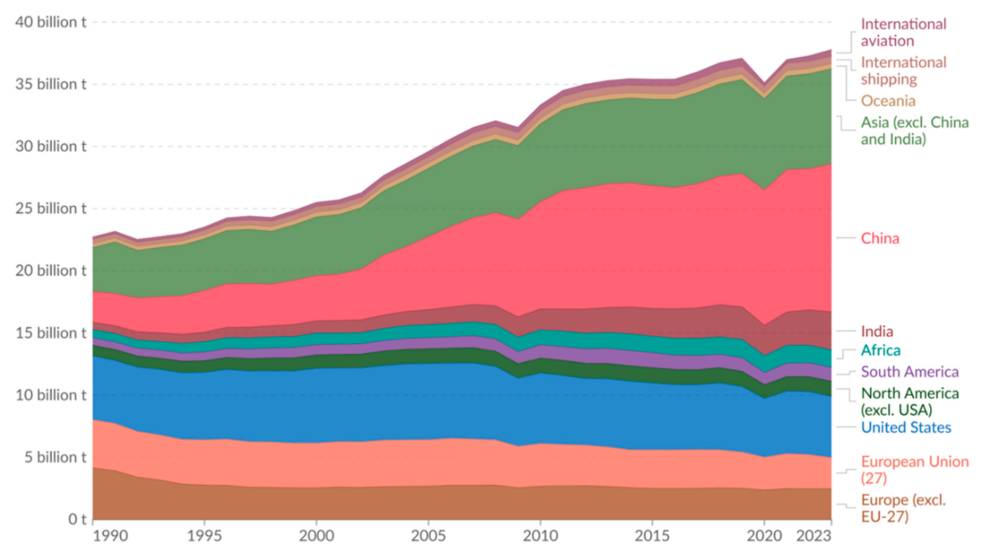
Figure 1. Annual CO2 emissions by world region from fossil fuels and industry. Data source: Global Carbon Budget (2024) [1].
Catalysts 15 00775 g001
Figure 2. (a) Operational schematic diagram of LT-PEMFC with methanol reformer [28]. Reproduced with permission. Copyright 2020, Elsevier. (b) Operational schematic diagram of HT-PEMFC with methanol reformer. Reprinted/adapted with permission from Ref. [38]. Copyright 2016, Elsevier.
Catalysts 15 00775 g002
Figure 3. Schematic diagram of HT-PEMFC.
Catalysts 15 00775 g003
Figure 4. Reaction mechanisms in HT-PEMFCs. (a) HOR pathways (Tafel step: red; Heyrovsky step: blue; Volmer step: black); (b) ORR proceeding via the two-electron transfer pathway; (c) ORR proceeding via the four-electron transfer pathway (associative route: black; dissociative route: red) [51].
Catalysts 15 00775 g004
Figure 6. Timeline demonstrating significant NPM catalyst developments for ORR in HT-PEMFCs.
Catalysts 15 00775 g006
Figure 7. PANI-Fe-C catalyst: (a) TEM image, (b) ADF-STEM image, and (c) EEL spectrum confirm the presence of Fe single atoms, N, and C. (d) Comparison of ORR performance. Reprinted/adapted with permission from Ref. [79]. Copyright 2014, American Chemical Society.
Catalysts 15 00775 g007
Figure 8. (a) Schematic of Fe3C formation, (b) AST test, (c) TEM image after AST test, (d) polarization and power density plot of Fe3C catalyst for evaluation of LT-PEMFC and HT-PEMFC performance, and (e) long-term stability test in LT-PEMFCs and HT-PEMFCs. Reprinted/adapted with permission from Ref. [82]. Copyright 2010, Royal Society of Chemistry.
Catalysts 15 00775 g008
Figure 9. (a) TEM image of FePhen@MOF-ArNH3, (b) ORR performance, and (c) HT-PEMFC polarization curve of FePhen@MOF-ArNH3. Insert: iR-corrected Tafel plot. (d) Fe K-edge XANES spectrum of FePhen@MOF-ArNH3 at 0.3 V vs. RHE in N2-saturated 0.1 M HClO4, with/without 100 mM H3PO4. Inset: Difference spectrum (Δμ = μ0.9V − μ0.3V). Reprinted/adapted with permission from Ref. [89]. Copyright 2018, American Chemical Society.
Catalysts 15 00775 g009
Figure 10. (a) Synthesis scheme for EDTA-Fe complex-derived catalyst. (b) HAADF-STEM micrograph of LEDFe5-NH3. (c) Catalyst morphology pre- and post-accelerated durability testing (ADT) in N2-saturated 0.1 M HClO4. (d) HT-PEMFC performance of LEDFe5-NH3 and commercial Pt/C as cathode at 150 °C. Reprinted/adapted with permission from Ref. [90]. Copyright 2020, American Chemical Society.
Catalysts 15 00775 g010
Figure 11. (a) BP-FeNC TEM. (b) 160 °C HT-PEMFC: BP-FeNC vs. Pt/C (60 wt%/20 wt%) [94]. Reproduced with permission. Copyright 2018, Elsevier. (c) Fe-N-C TEM. (d) Fe-N-C PEMFC output (160 °C) [95]. Reproduced with permission. Copyright 2018, Elsevier. (e) Durability: Four Fe-N-C catalysts (H2/O2, dry). (f) Voltage decay rates at 0.1 A cm−2 (0 → 90 h). Reprinted/adapted with permission from Ref. [96]. Copyright 2024, Elsevier.
Catalysts 15 00775 g011
Figure 12. (a) Three-dimensional D-Fe-PNC fabrication scheme; (b,c) ORR performance in O2-saturated 0.1 M HClO4 and 1 M H3PO4: (b) 3D-Fe-PNC and (c) Pt/C; (d,e) catalyst stability: (d) 3D-Fe-PNC and (e) 20% Pt/C pre-/post-10,000 CV ADT. Reprinted/adapted with permission from Ref. [101]. Copyright 2019, American Chemical Society.
Catalysts 15 00775 g012
Figure 13. (a) Fe-NCP fabrication strategy; (b) HAADF-STEM of Fe-NCP; (c) ORR polarization in 0.1 M H3PO4/O2; (d) 160 °C fuel cell: Fe-NCP vs. Pt/C (20 wt%). Reprinted/adapted with permission from Ref. [104]. Copyright 2022, Springer Nature.
Catalysts 15 00775 g013
Figure 14. (a) Preparation scheme for the FeNi-NC catalyst. (b) TEM image of FeNi-NC. (c) Impact of PA concentration on ORR electrocatalysis of FeNi-NC in O2-saturated 0.1 M HClO4. (d) Catalyst stability evaluated via ADT over 5000 cycles in O2-saturated 1 M H3PO4. Reprinted/adapted with permission from Ref. [112]. Copyright 2021, Elsevier.
Catalysts 15 00775 g014
Figure 15. (a) Fabrication strategy for MOF-based electrocatalysts; (b) TEM images of Fe–Sn–N–C; (c) ORR polarization measurements in O2-saturated 0.5 M H3PO4; (d) pre- and post- AST comparison of mass activities at 0.8 V. Reprinted/adapted with permission from Ref. [77]. Copyright 2025, American Chemical Society.
Catalysts 15 00775 g015
Figure 16. (a) STEM images for FeSA-G; (b) FT-EXAFS spectral analysis for FeSA-G, FePc, and metallic Fe; (c) LSV curve of FeSA-G and Pt/C; (d,e) HT-PEMFCs at 160 °C and 230 °C; (f) stability of cells at 0.5 V. Reprinted/adapted with permission from Ref. [120]. Copyright 2019, John Wiley and Sons.
Catalysts 15 00775 g016
Figure 17. (a) Schematic diagram for synthesis process of FeSA-CNTs; (b) HR-TEM image; (c) HT-PEMFC output using FeSA-CNT cathode at multiple temperatures; (d) stability comparison between Pt/C (0.6 V) and FeSA-CNTs (0.5 V, 240 °C). Reprinted/adapted with permission from Ref. [121]. Copyright 2021, Elsevier.
Catalysts 15 00775 g017
Figure 18. (a) FeCu/N-CNT synthesis scheme. (b) CNT surface STEM (circles: dual sites/isolated atoms). (c) Graphene-like sheet STEM (circles: FeCu nanoclusters). (d) HT-PEMFC output: Fe vs. FeCu/N-CNT cathodes (160/230 °C). (e) Stability: FeCu/N-CNTs (0.5 V) vs. Pt/C (0.6 V). Reprinted/adapted with permission from Ref. [122]. Copyright 2021, Elsevier.
Catalysts 15 00775 g018
Figure 19. (a) Synthetic pathway for PNC catalyst. (b,c) ORR durability comparison of PNC and 20% Pt/C in 0.1 M HClO4 (O2-saturated) at 10 mV s−1, tested with poisoning anions: 50 mM NO2 (NaNO2), 50 mM SO32− (NaHSO3), and 50 mM HPO42− (Na2HPO4). (d) ORR stability of 20% Pt/C versus PNC. (e) Performance and poison resistance of PNC (inset: anti-poisoning mechanism—NC/PC sites attract SOx/NOx/POx molecules, while PNC sites repel them). Reprinted/adapted with permission from Ref. [133]. Copyright 2018, John Wiley and Sons.
Catalysts 15 00775 g019
Table 1. Comparative overview of Low-Temperature (LT) and High-Temperature (HT) PEMFCs.
FeatureLT-PEMFCHT-PEMFC
Operating Temperature50–100 °C 120–200 °C
ElectrolytePerfluorosulfonic acid (PFSA) polymer (e.g., Nafion)Phosphoric acid (PA)-doped polymer (e.g., Polybenzimidazole, PBI)
Proton Conduction MechanismVehicular (via H2O molecules)Grotthuss (hopping via PA network)
Water ManagementRequires external humidification; prone to flooding/dehydrationNo external humidification needed; simplified water removal (vapor phase)
Thermal ManagementRequires large cooling system due to small ΔTSimplified with smaller cooling system due to large ΔT; high-quality waste heat
Fuel Impurity Tolerance (CO)Very low (<10 ppm)Very high (1–3%)
Typical Cathode CatalystPt/C, Pt-alloy/CPt/C, Pt-alloy/C
Typical Cathode Pt Loading0.1–0.4 mg cm−2>1.0 mg cm−2
Key AdvantagesFast start-up and high power densityFuel flexibility, simplified BoP, CHP potential, and enhanced kinetics
Key ChallengesWater management, CO poisoning, and high-purity H2 requirementCatalyst poisoning by phosphate, long-term durability, and acid management
Table 2. Quantitative performance and durability comparison of leading NPM catalysts in HT-PEMFC single-cell tests.
Catalyst TypeCathode Loading (mg cm−2)Anode CatalystMembraneTemp. (°C)Test ConditionsPeak Power Density (mW cm−2)Performance MetricDurability/DegradationRef.
Fe/C-7006.3Pt/CPA-doped PBI membrane120–180H2/O2, 2.0 bar60 @ 160 °C0.44 A cm−2 @ 0.8 V130 h[82]
BP-Fe-N-C7.8Pt/CPA-doped PBI membrane160H2/O2, 20 mL min−17000.57 A cm−2 @ 0.6 V34% loss @ 0.6 V
after 400 h
[94]
FePhen@MOF-ArNH32Commercial Advent
A1100W Pt GDE
PBI membrane200H2/O21370.55 A cm−2 @ 0.6 V-[89]
Fe-N-C2Pt/CPBI membrane160H2/O2, 500/400 sccm-0.65 V @ 0.2 A cm−2250 h[95]
Fe-N-C21Pt/CPA-doped BASF membrane150H2/O2, 200/600 mL min−12020 mA cm−2 @ 0.6 V-[97]
FeSA-G0.3FeSAPt/CSiO2 nanoparticle-doped PA/PBI membrane230H2/O2325353 mA cm−2 @ 0.5 V16% loss @ 0.5 V after 100 h[120]
LEDFe5-NH33.8Pt/CPA-doped PBI membrane150H2/O2, 1.5 bar2601260 mA cm−2 @ 0.2 V and 78 mA cm−2 @ 0.7 V-[90]
FeCu/N-CNTs4 (0.12FeCu)Pt/CSiO2 nanoparticle-doped PA/PBI membrane230H2/O2, 100 mL min−1302320 mA cm−2 @ 0.5 VNo loss @ 0.5 V after 100 h[122]
FeSA/HP4 (0.13Fe)Pt/CSiO2 nanoparticle-doped PA/PBI membrane240Anhydrous H2/O2, 150/100 sccm266365 mA cm−2 @ 0.5 V12% loss @ 0.5 V after 100 h[121]
Fe-NCP2.5Pt/CPA-doped PBI membrane160H2/O2357--[104]
CoFe-N-SiOCa3Pt/CPA-doped PBI membrane160H2/O2, 1.5/9.534- -[134]
Disclaimer/Publisher’s Note: The statements, opinions and data contained in all publications are solely those of the individual author(s) and contributor(s) and not of MDPI and/or the editor(s). MDPI and/or the editor(s) disclaim responsibility for any injury to people or property resulting from any ideas, methods, instructions or products referred to in the content.