Article

Development of Ni-P-N-C/Nickel Foam for Efficient Hydrogen Production via Urea Electro-Oxidation

by
Abdullah M. Aldawsari
*,
Maged N. Shaddad
* and
Saba A. Aladeemy
Department of Chemistry, College of Science and Humanities, Prince Sattam Bin Abdulaziz University, P.O. Box 173, Al-Kharj 11942, Saudi Arabia
*
Authors to whom correspondence should be addressed.
Catalysts 2025, 15(7), 662; https://doi.org/10.3390/catal15070662
Submission received: 30 May 2025 / Revised: 22 June 2025 / Accepted: 30 June 2025 / Published: 7 July 2025

Abstract

Electrocatalytic urea oxidation reaction (UOR) is a promising dual-purpose approach for hydrogen production and wastewater treatment, addressing critical energy and environmental challenges. However, conventional anode materials often suffer from limited active sites and high charge transfer resistance, restricting UOR efficiency. To overcome these issues, a novel NiP@PNC/NF electrocatalyst was developed via a one-step thermal annealing process under nitrogen, integrating nickel phosphide (NiP) with phosphorus and nitrogen co-doped carbon nanotubes (PNCs) on a nickel foam (NF) substrate. This design enhances catalytic activity and charge transfer, achieving current densities of 50 mA cm−2 at 1.34 V and 100 mA cm−2 at 1.43 V versus the reversible hydrogen electrode (RHE). The electrode’s high electrochemical surface area (235 cm2) and double-layer capacitance (94.1 mF) reflect abundant active sites, far surpassing NiP/NF (48 cm2, 15.8 mF) and PNC/NF (39.5 cm2, 12.9 mF). It maintains exceptional stability, with only a 16.3% performance loss after 35 h, as confirmed by HR-TEM showing an intact nanostructure. Our single-step annealing technique provides simplicity, scalability, and efficient integration of NiP nanoparticles inside a PNC matrix on nickel foam. This method enables consistent distribution and robust substrate adhesion, which are difficult to attain with multi-step or more intricate techniques.

Graphical Abstract

1. Introduction

The development of high-performance electrocatalysts for sustainable energy conversion represents a critical frontier in addressing global energy challenges and environmental concerns [1,2]. Hydrogen (H2) is a crucial clean and renewable energy carrier driving the global transition to sustainable energy models [3,4,5,6]. Water electrolysis is a viable hydrogen production method because of its ecological sustainability and industrial scalability [7,8,9]. However, anodic oxygen evolution reaction’s (OER) slow reaction kinetics increase the electrolytic process’s thermodynamic energy and operational costs, limiting its commercialization. This kinetic bottleneck diminishes the energy efficiency of water splitting and renders large-scale hydrogen production economically challenging [8,10,11,12]. The creation of highly efficient electrocatalysts that facilitate rapid OER kinetics is crucial for the practical implementation of electrolytic hydrogen production systems.
To overcome this obstacle, urea oxidation reaction (UOR) is a promising anodic process that offers thermodynamic and environmental benefits compared with OER. UOR mitigates urea-contaminated wastewater from intensive industrial and agricultural activities while fulfilling environmental requirements due to its advantageous thermodynamics and minimal overpotential [13,14,15,16,17]. This dual functionality renders UOR a groundbreaking approach for wastewater treatment and sustainable hydrogen production. Under applied electrical voltage, urea electrolysis oxidizes urea molecules at the anode and generates H2 at the cathode. The anodic reaction (Equation (1)) transforms urea into environmentally benign compounds such as nitrogen gas (N2) and carbon dioxide (CO2), whereas the cathodic hydrogen evolution reaction (Equation (2)) generates pure H2 gas [18,19]. Thermodynamic analysis indicates that UOR functions at a very low oxidation potential of 0.37 V relative to the reversible hydrogen electrode (RHE), in contrast with 1.23 V for conventional water electrolysis. This substantial thermodynamic benefit decreases energy use by 70%, rendering electrochemical hydrogen production commercially feasible [20,21,22]. The reduction in energy enhances process efficiency, rendering urea electrolysis a cost-effective and environmentally friendly approach for large-scale hydrogen production, while also aiding in wastewater treatment and environmental cleanup.
Anodic reaction: CO(NH2)2 + 6OH → N2 + CO2 + 5H2O + 6e
Cathodic reaction: 6H2O + 6e → 3H2 + 6OH
Transition metal electrocatalysts, particularly nickel-based systems, are favored for UOR applications due to their prevalence, economic efficiency, and catalytic properties. Nickel is a prominent electrocatalytic candidate; however, conventional synthetic processes are intricate and multi-faceted, limiting scalability [15,23,24]. Consequently, the study focus is on refined modification processes for nickel-based materials, especially nickel foam substrates that enhance structural integrity, economic feasibility, and catalytic efficacy.
Three-dimensional nickel foam (NF) has been demonstrated as a high-performance electrocatalyst substrate with high conductivity and a large surface area, exhibiting promising electrochemical performance for various reactions [25,26]. Despite these advances, nickel-based electrocatalysts often suffer from high overpotential demands and limited long-term stability. To mitigate these shortcomings, innovative materials engineering strategies, such as doping and structural modifications, have significantly enhanced the performance of transition metal-based catalysts [27,28,29]. Carbon nanotubes (CNTs) provide an effective platform for supporting metal-based catalysts, enabling the development of cost-effective electrocatalysts [30,31]. Additionally, the strategic incorporation of heteroatoms into CNT frameworks has proven to be a transformative approach for enhancing electrocatalytic properties. Dual doping of nitrogen (N) and phosphorus (P) provides remarkable synergistic effects that fundamentally alter the electronic structure: nitrogen atoms introduce electron-rich sites that enhance electron donation capabilities, while phosphorus atoms, with their larger atomic radius and lower electronegativity, create electron-deficient regions that facilitate charge transfer processes [9,32,33]. This dual heteroatom incorporation results in a redistribution of electron density, creating multiple active sites with optimized binding energies for urea molecules and intermediates [34]. Recently, the integration of nickel phosphide (NiP) with N and P co-doped CNTs has emerged as a particularly effective strategy for enhancing UOR performance [35]. These approaches have proven effective in lowering overpotentials, accelerating reaction kinetics, and bolstering stability during urea electrolysis.
Recent studies have explored the synergistic effects of heteroatom co-doping combined with structural modifications to achieve enhanced electrical conductivity and catalytic performance for UOR. For instance, Wu and colleagues [35] demonstrated the rapid synthesis of amorphous nickel phosphide deposited onto carbon nanotube-decorated nickel foam substrates (NiP/CNTs/NF) through a facile 3 min fabrication process. Electrochemical investigations revealed that the as-prepared electrocatalyst undergoes in situ surface reconstruction in alkaline media, resulting in the formation of hydrated nickel hydroxide (Ni(OH)2) nanocrystals. The reconstructed catalyst exhibited exceptional electrocatalytic activity toward urea oxidation, characterized by remarkably high current densities (~400 mA cm−2), favorable reaction kinetics evidenced by a low Tafel slope of 21 mV dec−1, and an impressive reaction rate constant of 1.1 × 106 cm3 mol−1 s−1. Qiao et al. [36] developed a hierarchical c-CoNiPx/a-P-MnOy composite as a bifunctional electrocatalyst for UOR and HER in alkaline media. The catalyst demonstrated exceptional UOR performance with potentials of 1.24 and 1.35 V at 10 and 100 mA cm−2, respectively, along with 300 h stability and efficient HER activity (0.18 mmol h−1, 97.2% Faradaic efficiency). The superior performance stems from (i) Co incorporation facilitating Ni2+/Ni3+ oxidation and NiOOH formation for UOR, (ii) conductive CoNiPx serving as the HER active phase, and (iii) the unique a-P-MnOy/c-CoNiPx configuration enhancing reactant adsorption and long-term stability. In a related work, Zhang et al. [37] synthesized hierarchical MnP/MnO@NiP on NF via electrodeposition for bifunctional HER and UOR catalysis. The Co-MnP/MnO@NiP/NF electrode required only 36.2 mV overpotential for HER and 1.24 V for UOR at 10 mA cm−2. Complete urea electrolysis achieved a 1.52 V cell voltage at 10 mA cm−2, representing a 300 mV reduction compared with conventional HER–OER systems. Enhanced performance was attributed to the protective MnOx layer, interfacial electron interactions, Co-induced electrochemical interface enhancement, and Ni-mediated NiOOH formation facilitating UOR activity. In the context of Ni-based catalysts for the urea oxidation reaction (UOR), two primary reaction mechanisms have been widely discussed in the literature: the indirect (chemical-oxidized) mechanism and the direct (electro-oxidized) mechanism. Both pathways involve the transformation of Ni(OH)2 to NiOOH, which serves as the catalytically active species.
In the indirect mechanism (chemical-oxidized path), Ni(OH)2 is first oxidized to NiOOH under applied potential, as shown in the following Equation (3):
Ni(OH)2 + OH → NiOOH + H2O + e
The chemically generated NiOOH then reacts with urea in the presence of water, resulting in the regeneration of Ni(OH)2 along with the evolution of nitrogen and carbon dioxide (Equation (4)), as follows:
6NiOOH + CO(NH2)2 + H2O → 6Ni(OH)2 + N2 + CO2
By contrast, the direct mechanism (electro-oxidized path) entails the simultaneous oxidation of both Ni(OH)2 and urea under electrochemical conditions. In this scenario, NiOOH interacts directly with urea and hydroxide ions, producing an intermediate, along with nitrogen, carbon dioxide, water, and a transfer of electrons, as shown in the following Equation (5):
[NiOOH + CO(NH2)2] + 6OH → [NiOOH·CO2] + N2 + 5H2O + 6e
Both mechanisms underscore the pivotal role of NiOOH as the active oxidant, but they differ in whether urea oxidation proceeds via a chemical reaction with NiOOH (indirect) or it does through a direct electrochemical process (direct). Elucidating which pathway is predominant under specific reaction conditions is essential for the rational design and optimization of Ni-based catalysts for efficient UOR performance [36].
This study introduces a novel NiP@PNC/NF electrocatalyst aimed at improving energy-efficient hydrogen production through the urea oxidation reaction, focusing on renewable energy generation and the environmental treatment of urea-contaminated wastewater. The electrocatalyst consists of NiP integrated with PNC on a porous, highly conductive NF substrate, produced using a simple one-step thermal annealing process in a nitrogen atmosphere. This unique architecture, consisting of P, N co-doped CNTs encased in a conformal NiP shell, ensures optimal catalyst loading, superior electrical conductivity, and enhanced mass transport, resulting in a high electrochemical surface area (ECSA) of 235 cm2 and a double-layer capacitance (Cdl) of 94.1 mF, significantly exceeding the performance of NiP/NF (ECSA: 48 cm2, Cdl: 15.8 mF) and PNC/NF (ECSA: 39.5 cm2, Cdl: 12.9 mF). The electrode exhibits remarkable long-term stability, with only a 16.3% reduction in performance after over 35 h of continuous operation, supported by high-resolution transmission electron microscopy (HR-TEM) images that reveal an unchanged nanostructure after testing. The durability results from the synergistic interaction between NiP and P, N co-doped CNTs, which improves electronic properties, increases active site density, and reduces reaction barriers. By employing multi-element doping and the structural advantages of NF, the NiP@PNC/NF electrocatalyst offers a cost-effective and sustainable solution for hydrogen production and wastewater treatment, positioning it as a promising candidate for urea-based fuel cells and environmental management applications. Our single-step annealing technique provides simplicity, scalability, and efficient integration of NiP nanoparticles inside a PNC matrix on nickel foam. This method enables consistent distribution and robust substrate adhesion, which are difficult to attain with multi-step or more intricate techniques.

2. Results

Developing high-performance, eco-friendly heterogeneous electrocatalysts for sustainable hydrogen production is vital for addressing global energy demands and mitigating environmental challenges. The choice of non-toxic, abundant, and atomically efficient raw materials, combined with environmentally conscious synthesis techniques, is paramount. Carbon nanotubes (CNTs), derived from renewable and non-toxic sources, improve catalyst wettability, facilitating enhanced interaction with electrolytes. Nickel phosphide, known for its high catalytic efficiency and low environmental impact, serves as an optimal precursor. Figure 1 provides a detailed schematic of the synthesis process for the NiP@PNC/NF electrocatalyst, outlining the step-by-step integration of NiP with PNC on NF substrate, highlighting the strategic design to achieve superior electrocatalytic performance for urea oxidation and hydrogen generation.

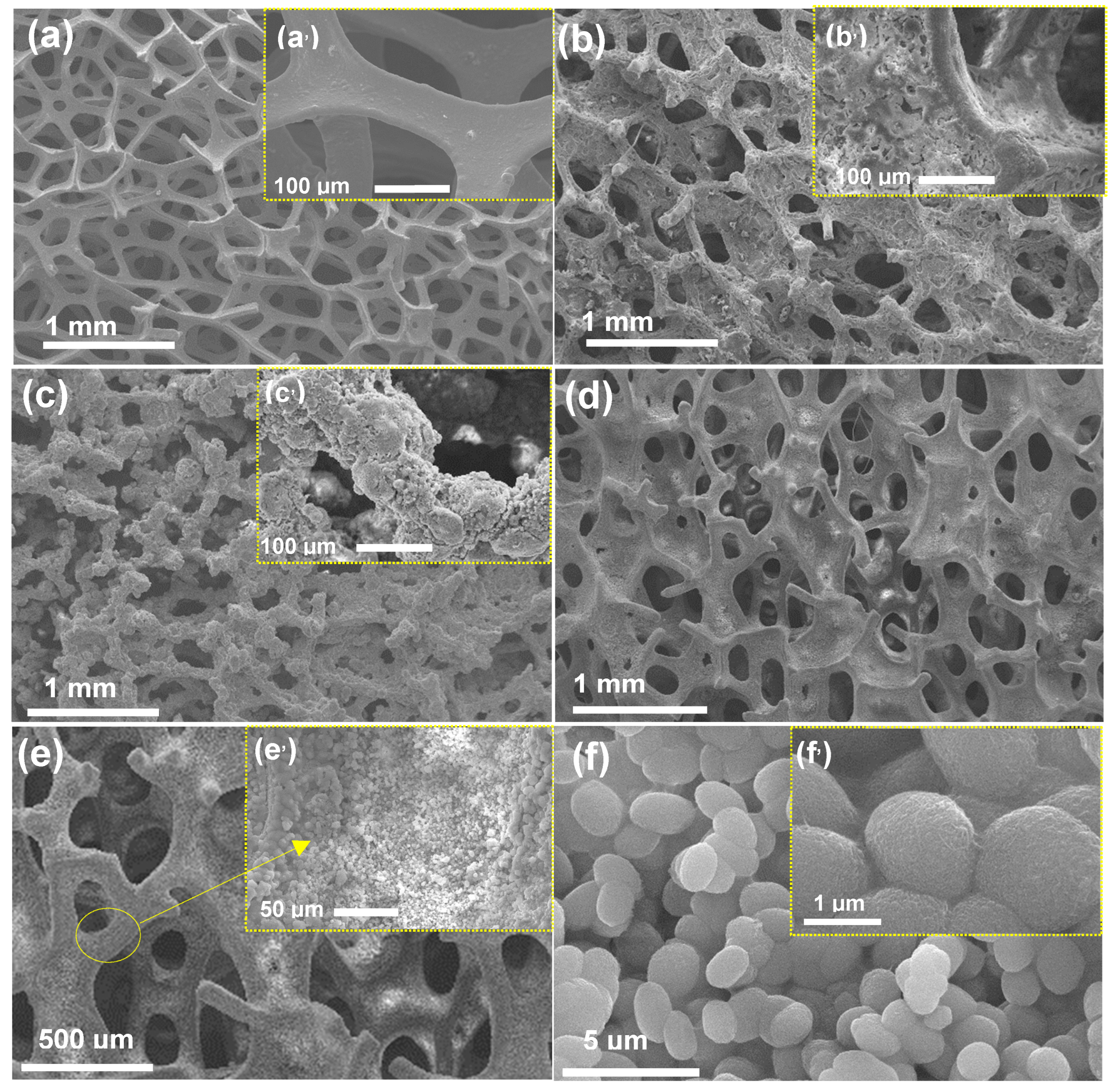
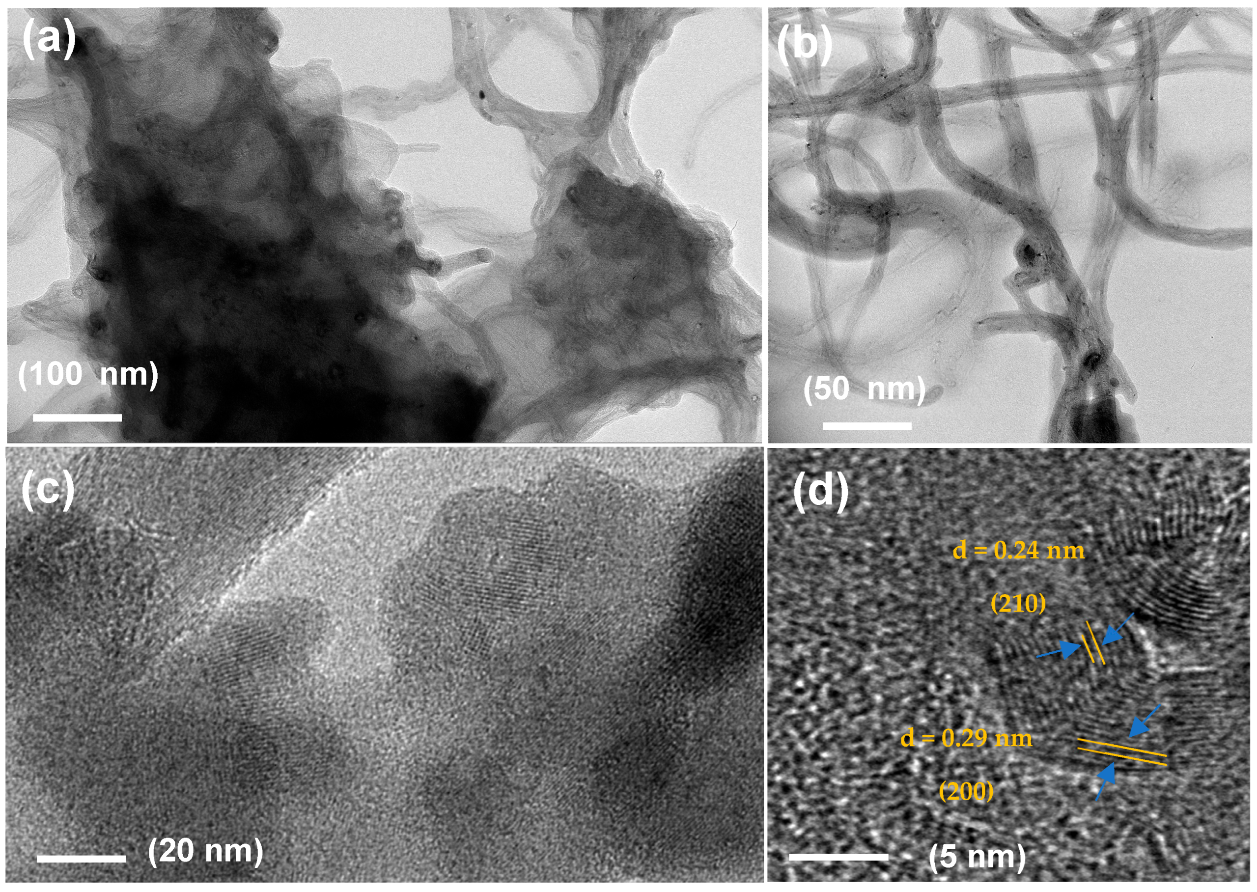
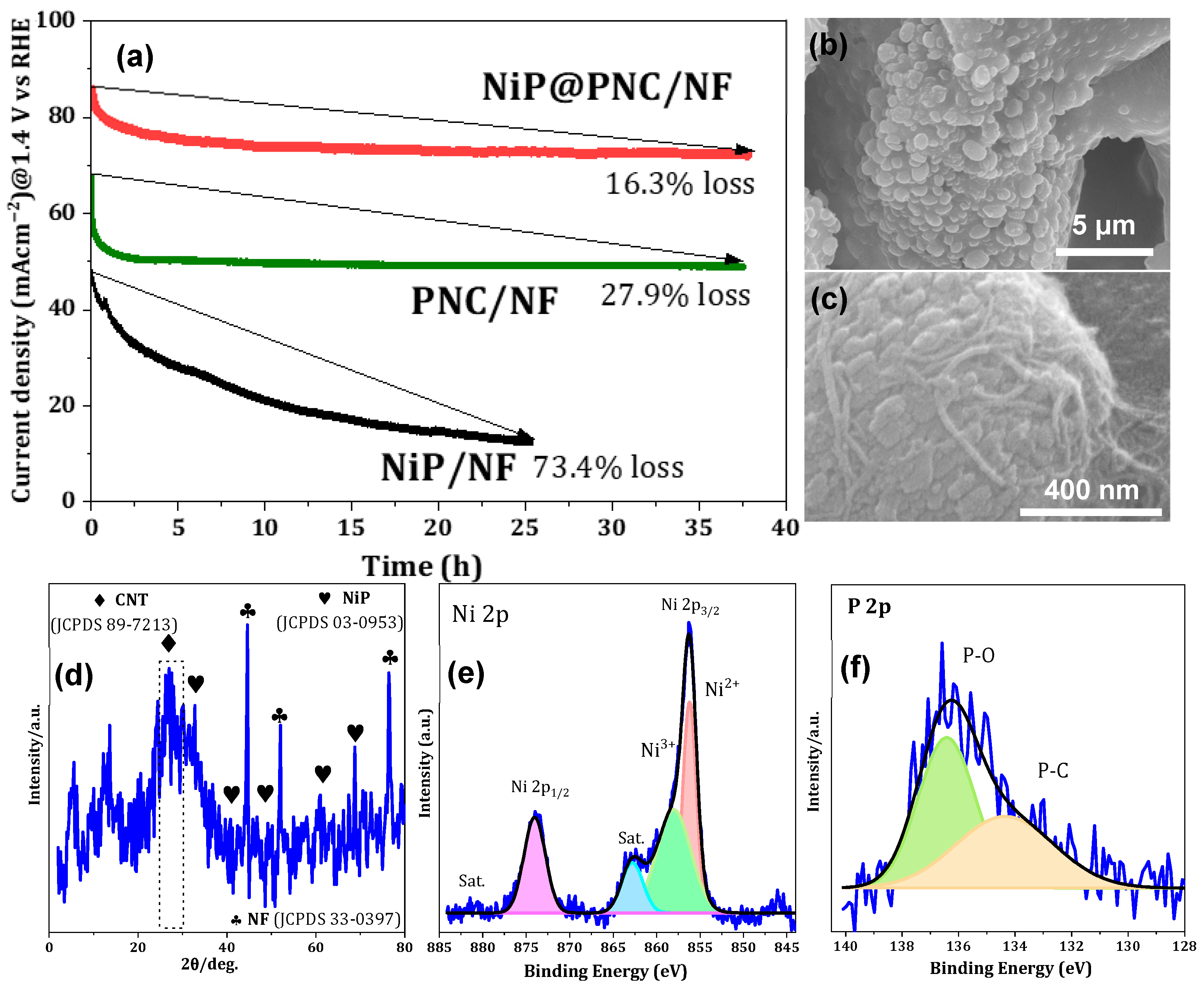
2.1. Morphological Features of NiP@PNC/NF

Scanning electron microscopy (SEM) was employed to meticulously analyze the surface morphology and microstructural features of the fabricated electrodes—bare nickel foam (NF), NiP/NF, PNC/NF, and NiP@PNC/NF—with comprehensive results presented in Figure 2. These images provide critical insights into the electrodes’ surface topography, structural configuration, and material distribution, confirming their suitability for electrocatalytic applications. Figure 2a (and its inset) showcases an SEM image of pristine NF, revealing a three-dimensional, highly porous framework characterized by a smooth surface and an interconnected lattice of macropores, ranging from approximately 50 to 500 μm in size [26,36]. This open, sponge-like structure maximizes the surface area, promoting efficient electrolyte diffusion and gas evolution during electrocatalytic processes. In Figure 2b (and inset), the NiP/NF electrode displays a non-uniform coating of nickel phosphide (NiP), comprising nanoparticles and small aggregates with sizes spanning 20 to 200 nanometers. The NiP preferentially accumulates in the NF’s recessed areas, corners, and crevices, forming a roughened surface that enhances catalytic activity while maintaining substrate conductivity through partially exposed NF regions. Figure 2c (and inset) illustrates the PNC/NF electrode, featuring a uniform, conformal coating of phosphorus and nitrogen co-doped carbon nanotubes (PNCs) on the NF substrate. The P, N co-doping introduces lattice imperfections and heteroatom incorporation, boosting electrical conductivity and electrocatalytic efficiency while preserving the NF’s macroporous architecture for optimal electrolyte access and an expanded electrochemically active surface area. Figure 2d,e depict the NiP@PNC/NF electrode, highlighting a sophisticated, hierarchical morphology driven by the synergistic integration of PNC and NiP. The PNC forms a web-like foundational layer that evenly coats the NF, with NiP nanoparticles intimately bonded to the CNTs, enhancing charge transfer and catalytic synergy, as evidenced in high-magnification views. High-resolution SEM images in Figure 2f (and inset) further validate the uniform dispersion of PNC and NiP across the NF, demonstrating structural integrity with minimal aggregation or uncoated regions. This consistent coating reflects the success of the synthesis and deposition process, achieving a harmonious blend of conductive PNC and catalytically active NiP, significantly elevating the electrode’s performance in UOR.
The nanostructure and compositional properties of the NiP@PNC/NF electrode were thoroughly investigated using high-resolution transmission electron microscopy (HR-TEM) at various magnifications, with detailed images showcased in Figure 3. As depicted in Figure 3a, a low-magnification TEM image reveals the intricate interplay between NiP nanoparticles and PNC within the electrode. The P, N co-doped CNTs appear as elongated, hollow tubular structures with smooth external surfaces, interspersed with occasional structural defects such as kinks, bends, or lattice distortions. These imperfections, induced by the incorporation of phosphorus and nitrogen heteroatoms into the carbon framework, significantly enhance the electrocatalytic performance of the CNTs by creating additional active sites and improving electronic conductivity through modified electronic states. The NiP nanoparticles are observed to be firmly anchored to the CNT surfaces, with some particles partially embedded within the CNT matrix, demonstrating strong interfacial bonding that promotes structural stability. This intimate NiP–PNC interaction facilitates efficient charge transfer, a critical factor in boosting the electrode’s electrocatalytic activity for UOR. Figure 3b, a high-magnification TEM image, provides a closer look at the NiP@PNC/NF electrode’s hybrid structure, highlighting the fine details of the NiP shell’s uniform coating over the PNC nanotubes and the nuanced compositional integration, further underscoring the material’s tailored design for enhanced electrocatalytic performance. Figure 3c,d present HR-TEM images of the NiP@PNC/NF sample. The observed lattice spacing of the crystalline nanoparticles is approximately 0.29 nm and 0.24 nm, which corresponds well with the characteristic (200) and (210) plane of NiP, as reported in the literature [35,36,37,38]. This observation further confirms the crystalline nature of the NiP phase in our synthesized material and supports its structural assignment.

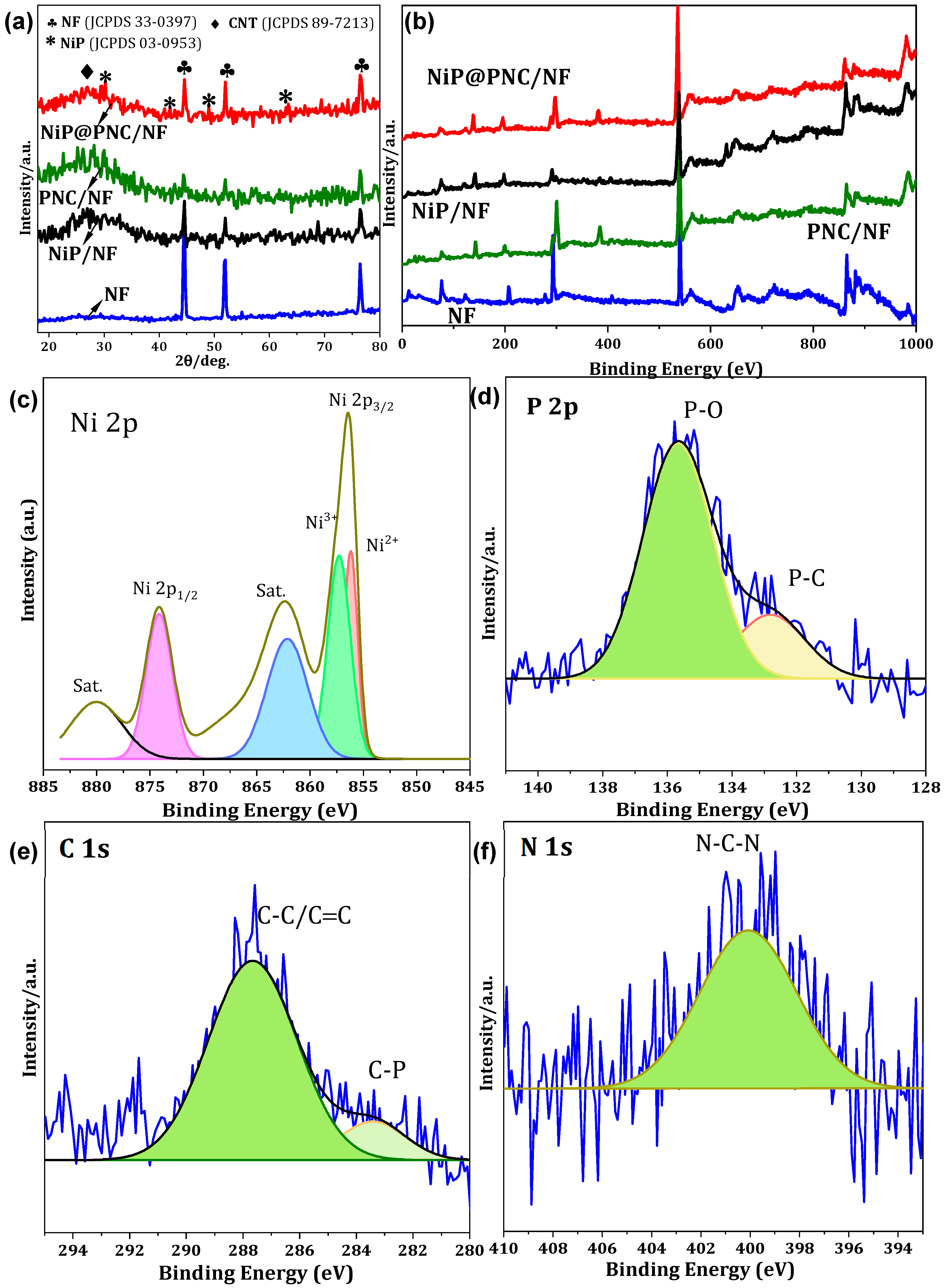
2.2. Crystalline and Chemical Composition Features of Electrodes

The X-ray diffraction (XRD) patterns for four electrode materials—bare nickel foam (NF), NiP/NF, PNC/NF, and NiP@PNC/NF—collected using a Cu Kα radiation source (λ = 1.5406 Å) throughout a 2θ range of 17° to 80° are shown in Figure 4a. The contributions of the NF substrate, nickel phosphide (NiP), and phosphorus and nitrogen co-doped carbon nanotubes (PNCs) to the architecture of the hybrid material are clarified by these patterns, which offer comprehensive insights into the crystallographic phase composition, crystallinity, and structural characteristics of each electrode. According to JCPDS card no. 01-1260, the XRD pattern of the uncoated NF substrate, represented by the green line, shows three distinct, sharp diffraction peaks at roughly 43.2°, 50.8°, and 74.7°. These peaks correspond to the (111), (200), and (220) planes of face-centered cubic (FCC) metallic nickel [38,39]. The NiP/NF electrode, shown by the black line, has three prominent NF peaks at 43.2°, 50.8°, and 74.7°, as well as two weaker peaks at about 38.1° and 48.3° that correspond to the (200) and (211) planes of orthorhombic NiP, according to JCPDS card no. 03-0953 [40]. These XRD patterns show the structural features of the NiP coating on the NF substrate. The complex composition of this hybrid material, which integrates P, N co-doped CNTs with NiP on the NF substrate, is reflected in the red line of the NiP@PNC/NF electrode’s XRD pattern. The diffraction signal is dominated by the high crystallinity and structural integrity of the NF substrate, as seen by the retention of the distinctive NF peaks at 43.2°, 50.8°, and 74.7°. Furthermore, as shown in JCPDS card no. 89-7213 [41], a broad, low-intensity peak at roughly 27.3° corresponds to the (002) plane of hexagonal graphitic carbon, verifying the existence of PNC within the electrode. This peak’s widening indicates a somewhat disordered graphitic structure, most likely brought on by lattice strain and defects brought on by the CNTs’ doping with nitrogen and phosphorus. The total efficiency of the NiP@PNC/NF electrode for urea oxidation and hydrogen production is increased by these structural flaws, which also improve the electronic characteristics and electrocatalytic performance of the CNTs by generating more active sites.
The catalysts placed on the substrate were carefully examined for surface elemental composition and chemical valence states using X-ray photoelectron spectroscopy (XPS). The presence of nickel (Ni), phosphorus (P), nitrogen (N), and carbon (C) in the samples was confirmed by the XPS survey spectrum, which is shown in Figure 4b and offers a thorough overview of the elemental elements on the catalyst surface. Significant peaks that correspond to the Ni 2p3/2 and Ni 2p1/2 core levels with binding energies of 856.6 eV and 873.7 eV, respectively, were found by a thorough high-resolution XPS study of the Ni 2p area, as seen in Figure 4c. These binding energies indicate that the nickel atoms are incorporated into the catalyst in an oxidized chemical state and are representative of nickel in oxidized forms, such as Ni2+ or Ni3+. Furthermore, satellite peaks linked to the Ni 2p3/2 and Ni 2p1/2 edges were detected at roughly 861.8 eV and 879.9 eV, respectively. The oxidized nickel environment within the catalyst matrix is further confirmed by these satellite features, which are the product of electron shake-up processes and are located at higher binding energies in relation to the principal Ni 2p peaks [5,6,17]. The P 2p3/2 and P 2p1/2 core levels of phosphorus species within the nickel phosphide (NiP) phase are represented by two separate peaks at binding energies of 132.7 eV and 135.6 eV, respectively, in the high-resolution P 2p spectra shown in Figure 4d [35]. According to these binding energy values, phosphorus and nickel are chemically bound to create stable nickel phosphide structures, which enhance the catalyst’s characteristics. Additionally, a single prominent peak at a binding energy of 399.8 eV, which is indicative of nitrogen in a pyrrolic form, was revealed by deconvolution of the N 1s spectrum [42], which is shown in Figure 4f. This suggests that nitrogen is integrated into the catalyst structure as a component of a heterocyclic ring system with five members, which probably affects the material’s chemical and electrical behavior. In conclusion, the XPS analysis confirms the presence of Ni, P, N, and C elements with certain valence states and bonding configurations, providing a thorough understanding of the catalyst’s surface chemistry. These revelations are essential for clarifying the catalyst’s structural and functional properties, emphasizing the functions of pyrrolic nitrogen, nickel phosphide phases, and oxidized nickel.

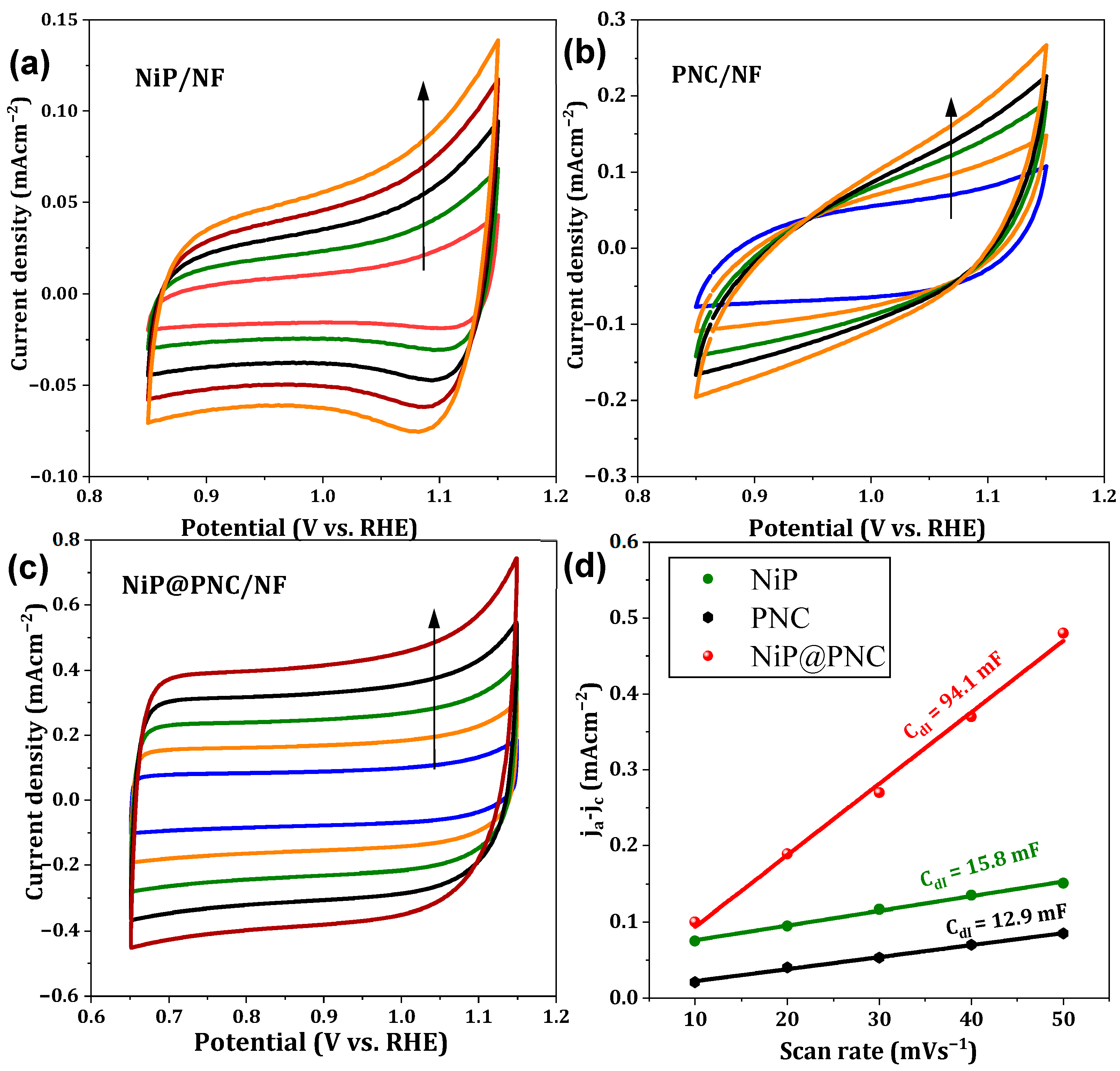
2.3. Electrochemical Properties of Catalysts

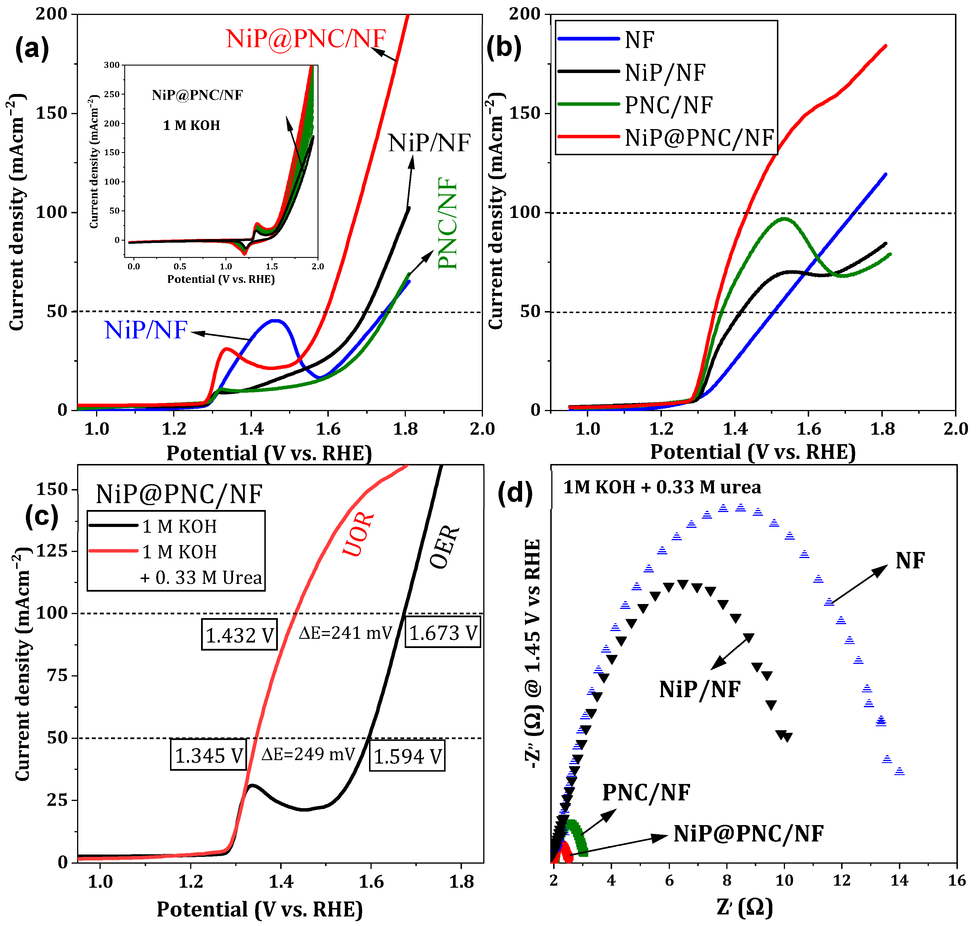
2.3.1. OER and UOR Characteristics

The electrocatalytic performances of four electrode configurations—bare NF, NiP/NF, PNC/NF, and NiP@PNC/NF—are compared in Figure 5a, which shows detailed current density versus voltage (j-v) plots for the OER carried out in a 1.0 M KOH electrolyte (pH 13.6). The catalysts’ OER efficiencies are comprehensively visualized by these linear sweep voltammetry (LSV) curves, which also show clear variations in their electrocatalytic activity under the same experimental setup. The figures show how the structural and compositional characteristics of each electrode affect its capacity to support the OER, a crucial procedure for uses like water splitting in alkaline electrolyzers. The same set of electrodes—NF, NiP/NF, PNC/NF, and NiP@PNC/NF—is evaluated in Figure 5b, which also shows j-v plots for the UOR carried out in an electrolyte made of 1.0 M KOH with 0.33 M urea. The UOR is an alternate anodic reaction that can lower energy requirements in electrochemical systems, and these curves show how well the catalysts function in catalyzing it. In comparison with the RHE, the NiP@PNC/NF electrode exhibits remarkable UOR performance, with an astonishingly high current density of 100 mA cm−2 at 1.43 V. The improved activity of the hybrid catalyst is shown by the fact that this current density is more than three times greater than that of the bare NF electrode at the same voltage. Additionally, in comparison with its counterparts, the NiP@PNC/NF electrode shows a much lower onset potential for OER, indicating lower energy barriers for starting the reaction and improved catalytic efficiency. Furthermore, LSV curves for the NiP@PNC/NF electrode in 1.0 M KOH, with and without 0.33 M urea, measured at a scan rate of 20 mV s−1 are included in Figure 5b. The performance of the electrode under OER and UOR conditions can be directly compared, thanks to these graphs. At high lower potential 1.34 V vs. RHE, the NiP@PNC/NF electrode obtains current densities of 50 mA cm−2 and 100 mA cm−2 at 1.43 V for UOR. The improved electrocatalytic efficiency of the NiP@PNC/NF electrode is demonstrated by this comparison. The electrochemical conversion of Ni2+ to Ni3+, a feature of nickel-based electrocatalysts, is responsible for an oxidation peak seen in the LSV curves at about 1.31 V vs. RHE. This process probably enhances the catalytic activity by promoting redox reactions at the electrode surface. Results from EIS at 1.45 V in 1.0 M KOH with 0.33 M urea are shown in Figure 5c, providing information on the electrodes’ charge transfer characteristics. Compared with the other electrodes examined, the NiP@PNC/NF electrode has an extraordinarily low charge transfer resistance (Rct) of 2.52 Ω. For effective electrocatalytic performance, this low Rct value denotes improved electrical conductivity and quicker charge-transfer kinetics. The hybrid NiP@PNC/NF architecture’s enhanced active site accessibility and optimized electrical structure are probably the causes of the decreased resistance.
These results are supported by Table 1, which lists the applied potentials needed for all investigated electrodes to reach current densities of 50, 100, and 200 mA cm−2 for both OER and UOR in 1.0 M KOH with 0.33 M urea. With the lowest potentials needed to reach these benchmark current densities, the NiP@PNC/NF electrode continuously performs better than the others. The synergistic effects of N and P within the carbon nanotube framework, along with the catalytic qualities of NiP on the NF substrate, are responsible for this better performance. The remarkable electrocatalytic activity of the NiP@PNC/NF electrode for both OER and UOR is a result of these interactions, which also promote charge transfer, expand the number of catalytically active sites, and improve the electronic configuration.
To evaluate the electrochemical properties of the electrodes, cyclic voltammetry (CV) experiments were performed within a potential window of 0.8–1.10 V versus the reversible hydrogen electrode (RHE). The CV measurements were conducted at varying scan rates of 10, 20, 30, 40, and 50 mV s−1 to determine the double-layer capacitance (Cdl), a key indicator of the electrochemically active surface area. As shown in Figure 6b–d, the calculated Cdl values clearly demonstrate the superior performance of the NiP@PNC/NF electrode, which achieved a Cdl of 94.1 mF. This value significantly exceeds that of the NiP/NF electrode (15.8 mF) and the PNC/NF electrode (12.9 mF), highlighting a marked improvement in charge storage capacity. The electrochemical surface area (ECSA) was subsequently derived from the Cdl values, providing further insight into the electrodes’ catalytic capabilities. The NiP@PNC/NF electrode exhibited an exceptionally high ECSA of 235 cm2, far surpassing the NiP/NF electrode (48 cm2) and the PNC/NF electrode (39.5 cm2), as illustrated in Figure 6. This substantially larger ECSA for NiP@PNC/NF indicates a greater abundance of catalytically active sites, which directly correlates with enhanced electrocatalytic activity for the urea oxidation reaction (UOR). The improved performance of NiP@PNC/NF can be attributed to the synergistic effects of the NiP shell layer and the P, N co-doped carbon nanotubes (CNTs) on the nickel foam (NF) substrate. These structural and chemical enhancements facilitate greater exposure of active sites, improve electron transfer, and boost overall catalytic efficiency, positioning NiP@PNC/NF as a highly effective electrocatalyst for UOR applications. Table 2 provides a comparative summary of the electrocatalytic UOR performance of various catalysts in 0.33 M urea, as measured by cyclic voltammetry. The NiP@PNC/NF catalyst developed in this study demonstrates excellent activity, achieving a high current density at a relatively low potential compared with other recently reported nickel-based and composite catalysts. While some references exhibit slightly lower overpotentials at lower current densities, the superior performance of NiP@PNC/NF at higher, industrially relevant current densities highlights its practical advantages for both hydrogen production and urea-rich wastewater treatment. These results underscore the catalyst’s strong competitiveness and its potential as an efficient and robust material for future electrochemical applications.

2.3.2. Long-Term Stability

The NiP@PNC/NF electrode has remarkable durability, with just a 16.3% decline in performance after over 35 h of operation, significantly outperforming its rivals. In contrast, the PNC/NF electrode experiences a 27.9% reduction, while the NiP/NF electrode incurs a substantial 73.4% decrease in performance during the same period. This significant difference in stability highlights a robust synergistic relationship between the NiP shell and the phosphorus, nitrogen co-doped carbon nanotubes (CNTs) on the nickel foam (NF) substrate. The combination of NiP and PNC enhances the electrode’s resistance to degradation, likely due to the improved structural integrity and catalytic effectiveness provided by the conformal NiP coating and the P-N co-doping inside the CNTs. This synergy improves the electrode’s exceptional long-term stability and efficiency in the urea oxidation reaction (UOR), underscoring its potential as an advanced, durable electrocatalyst. Following the urea oxidation reaction (UOR) stability test, high-resolution transmission electron microscopy (HR-TEM) images, depicted in Figure 7b,c, provided detailed insights into the structural integrity of the NiP@PNC/NF electrode after extended operation. The images demonstrated that the nanostructure of the NiP@PNC/NF electrode, comprising phosphorus and nitrogen co-doped carbon nanotubes (CNTs) with a NiP shell layer on nickel foam (NF), was remarkably intact with no discernible alterations. The exceptional structural stability was consistently seen in several produced samples, underscoring the resilience of the electrode design. The preserved morphology is attributed to the synergistic interaction between the NiP coating and the P, N co-doped CNTs, enhancing the electrode’s durability against degradation under prolonged UOR conditions. The structural integrity is closely associated with the NiP@PNC/NF electrode’s remarkable performance, evidenced by only a 16.3% reduction in performance after over 35 h and its ability to maintain high catalytic efficiency. These findings highlight the electrode’s potential as an exceptionally stable and efficient electrocatalyst for UOR applications. Furthermore, analysis of the J–t (current–time) stability test shows that the majority of the performance loss occurs during the initial phase of operation. After this initial decline, the current stabilizes and remains relatively constant for the remainder of the 35 h test period. This indicates that the electrode undergoes an initial activation or surface adjustment phase, after which stable performance is maintained. Consequently, while our test duration was 35 h, the observed stability after the initial period suggests the potential for extended operational durability beyond the tested timeframe.
While the current study does not include in situ or operando spectroscopic analyses, we have performed ex situ characterizations (such as XRD, XPS, SEM, and TEM) before and after the reaction, which suggest possible changes in the active sites. These findings, together with the observed electrochemical UOR performance trends, are consistent with the mechanisms proposed in previous reports [37]. Nevertheless, we recognize that direct evidence from in situ or operando studies would provide deeper insight into the reaction pathway. Incorporating such techniques is a priority for our future research and will help clarify the mechanistic aspects discussed herein.

3. Experimental Section

3.1. Materials

All chemicals used in this study were of analytical grade and used without further purification. Nickel(II) chloride hexahydrate (NiCl2·6H2O, 97.5%) and 85% phosphoric acid (H3PO4) were obtained from BDH Chemicals Ltd. (Poole Dorset, UK). Potassium hydroxide pellets (KOH, 85.0%) were supplied by the AnalaR Group (Helsinki, Finland). Melamine (C3H6N6, 99%) was purchased from PanReac (Castellar del Vallès, Spain), and urea (CH4N2O, 99%) from AVONCHEM Corp. (Macclesfield Cheshire, UK). Multi-walled carbon nanotubes (CNTs; 95% purity, outer diameter of 10–20 nm, length of 10–30 μm) were obtained from Sigma-Aldrich (St. Louis, MO, USA). The CNTs were used as received and were not subjected to further functionalization or purification unless otherwise stated.

3.2. Fabrication of Nip/NF Electrode

To make a uniform solution, 0.1 g of NiCl2 was dissolved in 1.0 M H3PO4 and stirred for 1 h at 50 °C. The solution maintained a constant temperature for an additional hour. The unadulterated NF substrate (1.0 × 2.0 cm2) was submerged for 2 min. The resultant NF was annealed at 600 °C for 2 h in an inert nitrogen environment with a flow rate equal 150 standard cubic centimeters per minute (sccm) prior to being dried overnight.

3.3. Fabrication of PNC/NF Electrode

A homogenous solution was obtained by agitating 0.1 g of melamine in a 1.0 M H3PO4 solution for 1 h at 50 °C. The previous solution was then mixed with 0.5 g of CNT and kept at the same temperature for an additional hour (molar ratio of melamine: CNT was (1:1)). For 2 min, the pristine NF substrate (1.0 × 2.0 cm2) was submerged. Before being dried overnight, the resulting NF was then annealed for 2 h at 600 °C in an inert nitrogen atmosphere (150 sccm).

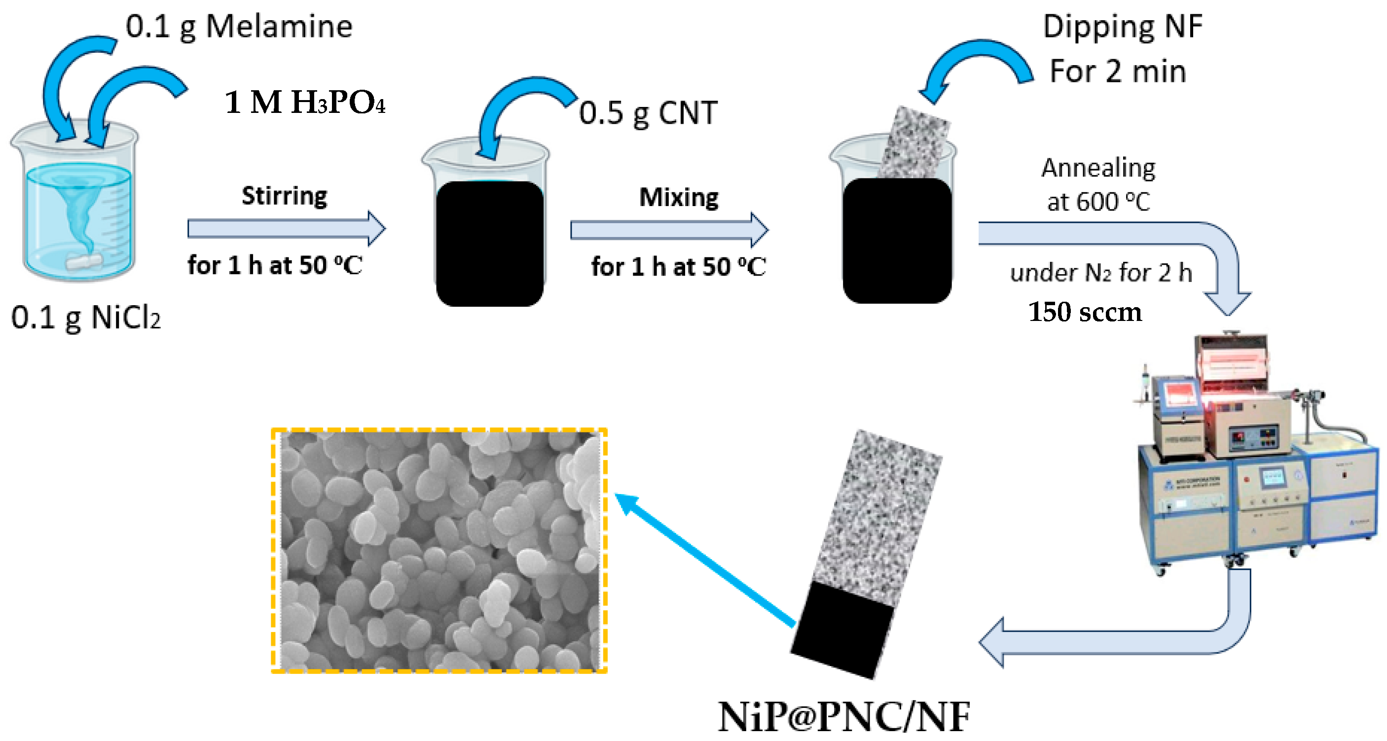
3.4. Fabrication of NiP@PNC/NF Electrode

A homogeneous solution was achieved by dissolving 0.1 g of NiCl2 and 0.1 g of melamine in a 1 M H3PO4 solution and stirring the mixture for 1 h at 50 °C. Then, for an additional hour, 0.5 g of CNT was added to the previously described solution at the same temperature (molar ratio of NiCl2: melamine: CNT was (1:1:5)). For 2 min, a pristine NF substrate measuring 1.0 × 2.0 cm2 was submerged. After 2 h of annealing at 600 °C in an inert nitrogen atmosphere (150 sccm), the coated nanofiber was left to dry overnight.

3.5. Characterization

The crystalline structure of the as-deposited catalyst was assessed via X-ray diffraction (XRD) utilizing a MiniFlex-600 (Rigaku, Tokyo, Japan) system, functioning with Cu Kα radiation at 40 kV and 15 mA. A Fourier-transform infrared (FTIR) spectroscopic analysis was conducted using a Bruker Tensor 27 spectrometer (Billerica, MA, USA) to examine the catalyst’s functional groups. The catalyst’s shape was analyzed using field-emission scanning electron microscopy (FE-SEM) utilizing a JSM-7610F equipment (JEOL Ltd., Akishima, Japan) at an accelerating voltage of 15 kV, supplemented by energy dispersive X-ray spectroscopy (EDX) for elemental composition assessment (JEOL Ltd., Akishima, Japan). Surface chemistry was evaluated using X-ray photoelectron spectroscopy (XPS) with a Thermo Fisher Scientific (Waltham, MA, USA) K-Alpha+ instrument, which produced high-resolution spectra in a vacuum environment. The textural properties of the catalyst were assessed by nitrogen (N2) adsorption–desorption isotherms obtained using a NOVA 2200e instrument (Anton Paar, Graz, Austria).

3.6. Electrochemical Measurements

A μ-AutolabIII/FRA2 system set up with three electrodes was used to analyze the electrochemical behavior of NiP, PNC, and NiP@PNC deposited onto a nickel foam (NF) electrode with an area of 0.5 × 0.5 cm2. The study focused on the urea oxidation reaction (UOR) and oxygen evolution reaction (OER) processes in a 1 M KOH solution (pH 13.6), both with and without 0.33 M urea added. A platinum counter electrode and a silver/silver chloride (Ag/AgCl) reference electrode were fitted to the experimental cell. Numerous electrochemical methods, such as chronoamperometry (CA), linear sweep voltammetry (LSV), cyclic voltammetry (CV), and electrochemical impedance spectroscopy (EIS), were used to assess the characteristics of these materials. All of these methods were managed by a PGSTAT30 system that was running NOVA 2.1 software. The results of these tests were methodically collected and recorded, and they were conducted in a Pyrex glass cell with a three-electrode configuration. The following formula was used to recalibrate the potentials recorded against the Ag/AgCl reference electrode to the reversible hydrogen electrode (RHE) scale:
ERHE = EAg|AgCl + 0.059pH + EoAg|AgCl
ERHE represents the conversion potential relative to RHE; EoAg|AgCl is 0.210 V at 25 °C.
Z-View software (ZMANTM2.3, Wonatech, Seoul, Republic of Korea) was used to perform electrochemical impedance spectroscopy (EIS) measurements in a solution of 1 M KOH + 0.33 M urea in the frequency range of 1 kHz to 0.05 Hz. For each scan rate (10–50 mVs−1), we measured the capacitive current at a certain potential in the non-Faradaic zone and plotted this current against the scan rate in order to calculate the double-layer capacitance (Cdl) from cyclic voltammetry (CV) data obtained at different scan rates. Cdl is represented by this linear graph’s gradient.

4. Conclusions

In conclusion, the NiP@PNC/NF electrode was successfully synthesized by depositing a composite coating onto nickel foam (NF) using a simple, efficient one-step thermal annealing method conducted in a nitrogen gas atmosphere. This process results in electrodes composed of phosphorus (P) and nitrogen (N) co-doped carbon nanotubes (CNTs) encapsulated by a nickel phosphide (NiP) shell layer, uniformly coated onto the NF substrate. The conformal nature of this coating ensures excellent adhesion and structural integrity, maximizing the exposure of catalytically active sites and enhancing electrochemical performance. The NiP@PNC/NF electrode exhibits remarkable electrocatalytic activity for the urea oxidation reaction (UOR), achieving a current density of 50 mA cm−2 at a potential of 1.34 V versus the reversible hydrogen electrode (RHE) and 100 mA cm−2 at 1.43 V. These metrics demonstrate its superior UOR performance compared with other electrode configurations. Furthermore, the NiP@PNC/NF electrode showcases exceptional long-term stability, maintaining its performance with minimal degradation over 35 h of continuous operation, as evidenced by a mere 16.3% loss in activity. This durability is attributed to the robust synergy between the NiP shell and the P, N co-doped CNTs, which enhances both the structural stability and the catalytic efficiency of the electrode. The use of a Ni catalyst during the synthesis process plays a pivotal role in enabling the formation of this advanced composite structure, marking a significant step forward in the development of high-performance NF-based electrodes. This study provides valuable insights into the role of P and N co-doping in enhancing electrocatalytic properties and proposes a comprehensive, cost-effective strategy for designing electrode materials that significantly improve UOR efficiency. Our single-step annealing technique provides simplicity, scalability, and efficient integration of NiP nanoparticles inside a PNC matrix on nickel foam. This method enables consistent distribution and robust substrate adhesion, which are difficult to attain with multi-step or more intricate techniques.

Author Contributions

A.M.A.: data curation, formal analysis, funding acquisition, project administration. M.N.S.: conceptualization, data curation, formal analysis, writing—review and editing. S.A.A.: data curation, writing—review and editing, formal analysis. All authors have read and agreed to the published version of the manuscript.

Funding

The authors extend their appreciation to Prince Sattam bin Abdulaziz University for funding this research work through project number PSAU/2024/01/31348.

Data Availability Statement

All data generated or analyzed during this study are included in this published article.

Conflicts of Interest

The authors declare no conflicts of interest.

References

  1. Christopher, K.; Dimitrios, R. A Review on Exergy Comparison of Hydrogen Production Methods from Renewable Energy Sources. Energy Environ. Sci. 2012, 5, 6640–6651. [Google Scholar] [CrossRef]
  2. Dunn, S. Hydrogen Futures: Toward a Sustainable Energy System. Int. J. Hydrogen Energy 2002, 27, 235–264. [Google Scholar] [CrossRef]
  3. Shaddad, M.N.; Alharthi, A.I.; Aladeemy, S.A.; Arunachalam, P. Engineering Oxygen Vacancy on Nickel-Doped Iron Oxide Nanorods as Efficient Bifunctional Electrocatalysts for Oxygen Evolution and Urea Oxidation Reaction. J. Taiwan Inst. Chem. Eng. 2024, 105928. [Google Scholar] [CrossRef]
  4. Al-Sulmi, W.A.; Ghanem, M.A.; Aladeemy, S.A.; Al-Mayouf, A.M.; Alotaibi, N.H. Chemical Deposition from a Liquid Crystal Template: A Highly Active Mesoporous Nickel Phosphate Electrocatalyst for Hydrogen Green Production via Urea. Arab. J. Chem. 2023, 16, 105266. [Google Scholar] [CrossRef]
  5. Aladeemy, S.A.; Arunachalam, P.; Amer, M.S.; Al-Mayouf, A.M. Electrochemically Embedded Heterostructured Ni/NiS Anchored onto Carbon Paper as Bifunctional Electrocatalysts for Urea Oxidation and Hydrogen Evolution Reaction. RSC Adv. 2025, 15, 14–25. [Google Scholar] [CrossRef]
  6. Aladeemy, S.A.; AlRijraji, T.R.; Amer, M.S.; Arunachalam, P.; Al-Mayouf, A.M. Electrooxidation of Ethylene Glycol Coupled with Hydrogen Production on Porous NiO/Ni@NF Nanosheet Electrocatalysts. Catal. Sci. Technol. 2025, 15, 2571–2583. [Google Scholar] [CrossRef]
  7. Arunachalam, P.; Shaddad, M.N.; Amer, M.S.; AL-Qadi, A. Enhanced Photoelectrochemical Water Splitting Coupled with Pharmaceutical Pollutants Degradation on Zr:BiVO4 Photoanodes by Synergetic Catalytic Activity of NiFeOOH Nanostructures. Alex. Eng. J. 2024, 99, 64–75. [Google Scholar] [CrossRef]
  8. Omar ben Gubaer, S.; Shaddad, M.N.; Arunachalam, P.; Amer, M.S.; Aladeemy, S.A.; Al-Mayouf, A.M. Enhanced Electrocatalytic Oxygen Redox Reactions of Iron Oxide Nanorod Films by Combining Oxygen Vacancy Formation and Cobalt Doping. RSC Adv. 2023, 13, 33242–33254. [Google Scholar] [CrossRef]
  9. Shaddad, M.N.; Alanazi, A.A.; Aldawsari, A.M.; Alotaibi, M.A.; Aladeemy, S.A.; Abdulaziz, F.; Aljohani, Y.S. Multifunctional Nitrogen Doped Carbon Nanotube-Encapsulated Defect-Rich Cobalt-Iron Oxide Catalyst for Efficient Water Electrolysis and and Dye Removal from Water. J. Ind. Eng. Chem. 2025, in press. [CrossRef]
  10. Zhang, W.; Cui, L.; Liu, J. Recent Advances in Cobalt-Based Electrocatalysts for Hydrogen and Oxygen Evolution Reactions. J. Alloys Compd. 2020, 19, 821. [Google Scholar] [CrossRef]
  11. Babar, N.U.A.; Joya, Y.F.; Khalil, H.; Hussain, F.; Joya, K.S. Thin-Film Iron-Oxide Nanobeads as Bifunctional Electrocatalyst for High Activity Overall Water Splitting. Int. J. Hydrogen Energy 2021, 46, 7885–7902. [Google Scholar] [CrossRef]
  12. Mohammed-Ibrahim, J. A Review on NiFe-Based Electrocatalysts for Efficient Alkaline Oxygen Evolution Reaction. J. Power Sources 2020, 448, 227375. [Google Scholar] [CrossRef]
  13. Wang, D.; Botte, G.G. In Situ X-Ray Diffraction Study of Urea Electrolysis on Nickel Catalysts. ECS Electrochem. Lett. 2014, 3, 29–32. [Google Scholar] [CrossRef]
  14. Vedharathinam, V.; Botte, G.G. Direct Evidence of the Mechanism for the Electro-Oxidation of Urea on Ni(OH)2 Catalyst in Alkaline Medium. Electrochim. Acta 2013, 108, 660–665. [Google Scholar] [CrossRef]
  15. Daramola, D.A.; Singh, D.; Botte, G.G. Dissociation Rates of Urea in the Presence of NiOOH Catalyst: A DFT Analysis. J. Phys. Chem. A 2010, 114, 11513–11521. [Google Scholar] [CrossRef]
  16. Hu, X.; Zhu, J.; Li, J.; Wu, Q. Urea Electrooxidation: Current Development and Understanding of Ni-Based Catalysts. ChemElectroChem 2020, 7, 3211–3228. [Google Scholar] [CrossRef]
  17. Aladeemy, S.A.; Arunachalam, P.; Al-Mayouf, A.M.; Sudha, P.N.; Rekha, A.; Vidhya, A.; Hemapriya, J.; Latha, S.; Prasad, P.S.; Pavithra, S.; et al. Engineered CoS/Ni3S2 Heterointerface Catalysts Grown Directly on Carbon Paper as an Efficient Electrocatalyst for Urea Oxidation. Catalysts 2024, 14, 570. [Google Scholar] [CrossRef]
  18. Wu, T.H.; Hou, B.W. Superior Catalytic Activity of α-Ni(OH)2 for Urea Electrolysis. Catal. Sci. Technol. 2021, 11, 4294–4300. [Google Scholar] [CrossRef]
  19. Yan, W.; Wang, D.; Botte, G.G. Nickel and Cobalt Bimetallic Hydroxide Catalysts for Urea Electro-Oxidation. Electrochim. Acta 2012, 61, 25–30. [Google Scholar] [CrossRef]
  20. Shaddad, M.N.; Alotaibi, M.A.; Alharthi, A.I.; Alanazi, A.A. Nickel Hexacyanoferrate on Nitrogen-Rich CNTs: An Efficient Bi-Functional Catalyst for Crystal Violet Removal and Electrochemical Urea Oxidation. Mater. Res. Bull. 2025, 185, 113300. [Google Scholar] [CrossRef]
  21. Aladeemy, S.A.; Al-Mayouf, A.; Amer, M.; Alotaibi, N.; Weller, M.T.; Ghanem, M.A. Structure and Electrochemical Activity of Nickel Aluminium Fl Uoride Nanosheets during Urea Electro-Oxidation in an Alkaline Solution. RSC Adv. 2021, 11, 3190–3201. [Google Scholar] [CrossRef]
  22. Aladeemy, S.A.; Al-Mayouf, A.M.; Shaddad, M.N.; Amer, M.S.; Almutairi, N.K.; Ghanem, M.A.; Alotaibi, N.H.; Arunachalam, P. Electrooxidation of Urea in Alkaline Solution Using Nickel Hydroxide Activated Carbon Paper Electrodeposited from DMSO Solution. Catalysts 2021, 11, 102. [Google Scholar] [CrossRef]
  23. Ma, Y.; Ma, C.; Wang, Y.; Wang, K. Advanced Nickel-Based Catalysts for Urea Oxidation Reaction: Challenges and Developments. Catalysts 2022, 12, 337. [Google Scholar] [CrossRef]
  24. Singh, R.K.; Schechter, A. Electrochemical Investigation of Urea Oxidation Reaction on β Ni(OH)2 and Ni/Ni(OH)2. Electrochim. Acta 2018, 278, 405–411. [Google Scholar] [CrossRef]
  25. Chaudhari, N.K.; Jin, H.; Kim, B.; Lee, K. Nanostructured Materials on 3D Nickel Foam as Electrocatalysts for Water Splitting. Nanoscale 2017, 9, 12231–12247. [Google Scholar] [CrossRef]
  26. Hu, X.; Tian, X.; Lin, Y.-W.; Wang, Z. Nickel Foam and Stainless Steel Mesh as Electrocatalysts for Hydrogen Evolution Reaction, Oxygen Evolution Reaction and Overall Water Splitting in Alkaline Media. RSC Adv. 2019, 9, 31563–31571. [Google Scholar] [CrossRef]
  27. Kumar, V.; Ahlawat, D.S.; AarifUl Islam, S.; Singh, A. Ce Doping Induced Modifications in Structural, Electrical and Magnetic Behaviour of Hematite Nanoparticles. Mater. Sci. Eng. B 2021, 272, 115327. [Google Scholar] [CrossRef]
  28. Abd El-Lateef, H.M.; Khalaf, M.M.; Mohamed, I.M.A. Advances in Phosphorus-Based Catalysts for Urea Electrooxidation: A Pathway to Sustainable Waste to Energy Conversion Through Electrocatalysis. Catalysts 2024, 14, 937. [Google Scholar] [CrossRef]
  29. Eom, S.; Jung, J.; Kim, D.H. One-Pot Synthesis of Nanostructured Ni@Ni(OH)2 and Co-Doped Ni@Ni(OH)2 via Chemical Reduction Method for Supercapacitor Applications. Materials. 2023, 16, 380. [Google Scholar] [CrossRef]
  30. Su, J.; Musgrave, C.B.; Song, Y.; Huang, L.; Liu, Y.; Li, G.; Xin, Y.; Xiong, P.; Li, M.M.-J.; Wu, H.; et al. Strain Enhances the Activity of Molecular Electrocatalysts via Carbon Nanotube Supports. Nat. Catal. 2023, 6, 818–828. [Google Scholar] [CrossRef]
  31. Aslam, M.M.A.; Kuo, H.W.; Den, W.; Usman, M.; Sultan, M.; Ashraf, H. Functionalized Carbon Nanotubes (CNTs) for Water and Wastewater Treatment: Preparation to Application. Sustainability 2021, 13, 5717. [Google Scholar] [CrossRef]
  32. Yao, C.; Xu, J.; Zhu, Y.; Zhang, R.; Shen, Y.; Xie, A. Porous CoP@N/P Co-Doped Carbon/CNTs Nanocubes: In-Situ Autocatalytic Synthesis and Excellent Performance as the Anode for Lithium-Ion Batteries. Appl. Surf. Sci. 2020, 513, 145777. [Google Scholar] [CrossRef]
  33. Scardamaglia, M.; Amati, M.; Llorente, B.; Mudimela, P.; Colomer, J.-F.F.; Ghijsen, J.; Ewels, C.; Snyders, R.; Gregoratti, L.; Bittencourt, C. Nitrogen Ion Casting on Vertically Aligned Carbon Nanotubes: Tip and Sidewall Chemical Modification. Carbon N. Y. 2014, 77, 319–328. [Google Scholar] [CrossRef]
  34. Zhang, L.; Luo, S.-H.; Li, P.; Qian, L.; Li, P.; Yan, S. Highly Dispersed Fe-Doped CoP Nanoparticles Encapsulated with P, N Co-Doped Hollow Carbon Shell toward Robust Bifunctional Oxygen Electrocatalysis and Rechargeable Li–O2 Batteries. Int. J. Hydrogen Energy 2024, 53, 49–59. [Google Scholar] [CrossRef]
  35. Wu, T.-H.; Qiu, Z.-T.; Hsieh, C.-N. Obtaining Ni P Electrocatalyst in Minutes via Electroless Plating on Carbon Nanotubes Decorated Substrate for Alkaline Urea Electrolysis. Appl. Surf. Sci. 2024, 645, 158831. [Google Scholar] [CrossRef]
  36. Qiao, L.; Zhu, A.; Liu, D.; Feng, J.; Chen, Y.; Chen, M.; Zhou, P.; Yin, L.; Wu, R.; Ng, K.W.; et al. Crystalline Phosphides/Amorphous Oxides Composite for Energy-Saving Hydrogen Production Assisted by Efficient Urea Oxidation Reaction. Chem. Eng. J. 2023, 454, 140380. [Google Scholar] [CrossRef]
  37. Zhang, R.; Gao, X.; Zhang, K.; Duan, D.; Zhou, X.; Wang, J.; Liu, S. Electrodeposition Synthesis of Co-MnP/MnO@NiP/NF Catalytic Materials and Investigation of Their Performance in Hydrogen Evolution Reaction and Urea Oxidation Reaction. Appl. Surf. Sci. 2025, 688, 162464. [Google Scholar] [CrossRef]
  38. Ehsan, M.A.; Ullah, Z.; Nazar, M.F.; Younas, M.; Suliman, M. One Step Fabrication of Nanostructured Nickel Thin Films on Porous Nickel Foam for Drastic Electrocatalytic Oxygen Evolution. Int. J. Hydrogen Energy 2023, 48, 15784–15795. [Google Scholar] [CrossRef]
  39. Luo, K.-H.; Cheng, C.-K.; Lin, J.-Y.; Huang, C.-H.; Yeh, T.-K.; Hsieh, C.-K. Highly-Porous Hierarchically Microstructure of Graphene-Decorated Nickel Foam Supported Two-Dimensional Quadrilateral Shapes of Cobalt Sulfide Nanosheets as Efficient Electrode for Methanol Oxidation. Surf. Coatings Technol. 2020, 393, 125850. [Google Scholar] [CrossRef]
  40. Wang, H.; Zou, H.; Liu, Y.; Liu, Z.; Sun, W.; Lin, K.A.; Li, T.; Luo, S. Ni2P Nanocrystals Embedded Ni-MOF Nanosheets Supported on Nickel Foam as Bifunctional Electrocatalyst for Urea Electrolysis. Sci. Rep. 2021, 11, 21414. [Google Scholar] [CrossRef]
  41. Zhang, J.; Chen, J.; Wang, X.; Ma, Y.; Li, Y.; Yang, X.; Li, Y. Multi-Electron Transfer Mechanism and Band Structures of CNTs in MOF-Derived CNTs/Co Hybrids for Enhanced Electromagnetic Wave Absorption Property. Mater. Today Commun. 2024, 39, 108936. [Google Scholar] [CrossRef]
  42. Morant, C.; Andrey, J.; Prieto, P.; Mendiola, D.; Sanz, J.M.; Elizalde, E. XPS Characterization of Nitrogen-Doped Carbon Nanotubes. Phys. Status Solidi Appl. Mater. Sci. 2006, 203, 1069–1075. [Google Scholar] [CrossRef]
  43. Cao, Z.; Zhou, T.; Ma, X.; Shen, Y.; Deng, Q.; Zhang, W.; Zhao, Y. Hydrogen Production from Urea Sewage on NiFe-Based Porous Electrocatalysts. ACS Sustain. Chem. Eng. 2020, 8, 11007–11015. [Google Scholar] [CrossRef]
  44. Yuan, M.; Wang, R.; Sun, Z.; Lin, L.; Yang, H.; Li, H.; Nan, C.; Sun, G.; Ma, S. Morphology-Controlled Synthesis of Ni-MOFs with Highly Enhanced Electrocatalytic Performance for Urea Oxidation. Inorg. Chem. 2019, 58, 11449–11457. [Google Scholar] [CrossRef]
  45. He, M.; Feng, C.; Liao, T.; Hu, S.; Wu, H.; Sun, Z. Low-Cost Ni2P/Ni0.96S Heterostructured Bifunctional Electrocatalyst toward Highly Efficient Overall Urea-Water Electrolysis. ACS Appl. Mater. Interfaces 2020, 12, 2225–2233. [Google Scholar] [CrossRef]
  46. Zhang, J.; Xing, F.; Zhang, H.; Huang, Y. Ultrafine NiFe Clusters Anchored on N-Doped Carbon as Bifunctional Electrocatalysts for Efficient Water and Urea Oxidation. Dalt. Trans. 2020, 49, 13962–13969. [Google Scholar] [CrossRef]
  47. Wen, X. NiFe-LDH/MWCNTs/NF Nanohybrids as a High-Performance Bifunctional Electrocatalyst for Overall Urea Electrolysis. Int. J. Hydrogen Energy 2020, 45, 14660–14668. [Google Scholar] [CrossRef]
  48. Rezaee, S.; Shahrokhian, S. 3D Ternary Ni: XCo2- XP/C Nanoflower/Nanourchin Arrays Grown on HCNs: A Highly Efficient Bi-Functional Electrocatalyst for Boosting Hydrogen Production via the Urea Electro-Oxidation Reaction. Nanoscale 2020, 12, 16123–16135. [Google Scholar] [CrossRef]
  49. Zhang, H.; Meng, X.; Zhang, J.; Huang, Y. Hierarchical NiFe Hydroxide/Ni3N Nanosheet-on-Nanosheet Heterostructures for Bifunctional Oxygen Evolution and Urea Oxidation Reactions. ACS Sustain. Chem. Eng. 2021, 9, 12584–12590. [Google Scholar] [CrossRef]
  50. Lv, Z.; Li, Z.; Tan, X.; Li, Z.; Wang, R.; Wen, M.; Liu, X.; Wang, G.; Xie, G.; Jiang, L. One-Step Electrodeposited NiFeMo Hybrid Film for Efficient Hydrogen Production via Urea Electrolysis and Water Splitting. Appl. Surf. Sci. 2021, 552, 149514. [Google Scholar] [CrossRef]
Figure 1. This figure illustrates the preparation process for the NiP@PNC/NF catalyst. It outlines the synthetic route for fabricating NiP@PNC/NF, detailing the key steps involved in its synthesis to achieve the desired composite structure (The molar ratio of NiCl2: melamine: CNT was (1:1:5)).
Catalysts 15 00662 g001
Figure 2. This figure highlights the morphological characteristics of various electrodes. Panels (a,a’) show FE-SEM top-view images of bare NF, revealing its surface structure. Panels (b,b’) display FE-SEM images of NiP/NF, illustrating its surface morphology. Panels (c,c’) present FE-SEM images of PNC/NF, showcasing its distinct texture. Panel (d) depicts a top-view FE-SEM image of NiP@PNC/NF. Panels (e,e’,f,f’) provide FE-SEM images of NiP@PNC/NF at different magnifications, offering detailed insights into its surface features and nanostructure.
Catalysts 15 00662 g002
Figure 3. Morphological analysis of the NiP@PNC/NF electrode. Panels (ad) display TEM and HR-TEM images at different magnifications, illustrating the detailed nanostructure and surface morphology of NiP nanoparticles embedded within the PNC matrix on nickel foam.
Catalysts 15 00662 g003
Figure 4. This figure illustrates the crystalline and chemical properties of various electrodes. Panel (a) displays X-ray diffraction (XRD) patterns for NF, PNC/NF, NiP/NF, and NiP@PNC/NF, revealing their crystalline structures. Panel (b) presents survey X-ray photoelectron spectroscopy (XPS) spectra for PNC/NF, NiP/NF, and NiP@PNC/NF, identifying the elemental composition on the electrode surfaces. Panels (cf) show high-resolution XPS spectra for the Ni 2p, P 2p, N 1s, and C 1s regions, providing detailed insights into the chemical states and bonding configurations of nickel, phosphorus, carbon, and nitrogen in the catalysts.
Catalysts 15 00662 g004
Figure 5. (a) presents electrochemical characterizations of various catalysts in 1.0 M KOH. Panel (a) shows linear sweep voltammetry (LSV) curves for the oxygen evolution reaction (OER) of bare nickel foam (NF), NiP/NF, PNC/NF, and NiP@PNC/NF. Panel (b) displays LSV curves for the urea oxidation reaction (UOR) for the same catalysts in 1.0 M KOH with 0.33 M urea. Panel (c) compares LSV curves for NiP@PNC/NF in 1.0 M KOH with and without 0.33 M urea, highlighting the effect of urea on its performance. Panel (d) illustrates electrochemical impedance spectroscopy (EIS) patterns for NF, NiP/NF, PNC/NF, and NiP@PNC/NF in 1.0 M KOH with 0.33 M urea, revealing charge transfer characteristics. All experiments were conducted at a scan rate of 20 mV/s in 1.0 M KOH, with or without 0.33 M urea.
Catalysts 15 00662 g005
Figure 6. This figure shows capacitive current measurements in 1.0 M KOH for NiP/NF (a), PNC/NF (b), and NiP@PNC/NF (c), along with the correlation between double-layer capacitances and various scan rates for the prepared catalysts (d).
Catalysts 15 00662 g006
Figure 7. (a) displays the long-term stability test results for NiP/NF, PNC/NF, and NiP@PNC/NF catalysts at 1.4 V versus RHE, evaluating their stability over extended operation. (bf) display FE-SEM images, XRD patterns, and high-resolution XPS spectra of the Ni 2p and P 2p regions for NiP@PNC/NF after the stability test. Post-stability HRTEM analysis reveals no observable changes in the surface morphology or structural characteristics of the catalyst. The XRD patterns further confirm that the crystalline structure remains intact, while the XPS results indicate no significant loss of key elements or alterations in surface chemical states.
Catalysts 15 00662 g007
Table 1. This table summarizes the electrochemical performance of bare nickel foam (NF), NiP/NF, PNC/NF, and NiP@PNC/NF catalysts for the oxygen evolution reaction (OER) and urea oxidation reaction (UOR) in 1.0 M KOH with 0.33 M urea. It lists the potentials required to achieve current densities of 50 and 100 mA cm−2, providing a comparative analysis of the catalysts’ efficiency in these electrocatalytic processes.
ElectrodesOERUOR
50 mAcm−2100 mAcm−250 mAcm−2100 mAcm−2
NF1.695 V 1.80 1.48 V1.72 V
NiP/NF1.63 V-1.414 V -
PNC/NF1.74 V-1.365 V -
NiP@PNC/NF1.594 V1.673 V1.345 V1.432 V
Table 2. Electrocatalytic performance comparison for UORs of different catalysts in 0.33 M urea, evaluated via cyclic voltammetry measurements.
Anodic MaterialsUrea (M)Stability (h)Potential
(V vs. RHE)
J
(mAcm−2)
Ref.
c-CoNiPx/a-P-MnOy0.333001.3350[36]
Co-MnP/MnO@NiP/NF0.33601.4150[37]
NP-Ni0.70Fe0.30, NP-Ni0.33101.5150[43]
Ni-MOF nanowires0.33114250[44]
Ni2P/Ni0.96S0.33201.41550[45]
NiFe/N-C0.331213750[46]
NiFe-LDH/MWCNTs/NF0.3331.40550[47]
Ni0.4Co1.6P/C@HCNs/GCE0.33101.4550[48]
NiFe(OH)x/Ni3N0.33101.3850[49]
NiFeMo0.33251.4450[50]
NiP@PNC/NF0.33~351.3450This work
Disclaimer/Publisher’s Note: The statements, opinions and data contained in all publications are solely those of the individual author(s) and contributor(s) and not of MDPI and/or the editor(s). MDPI and/or the editor(s) disclaim responsibility for any injury to people or property resulting from any ideas, methods, instructions or products referred to in the content.

