Abstract
The oxygen evolution reaction (OER) plays a central role as an anode in electrocatalytic processes such as energy conversion and storage and the generation of molecular oxygen from the electrolysis of water. Currently, precious metal oxides such as IrO2 and RuO2 are recognized as reference OER electrocatalysts with reasonably high activity; however, their widespread use in practical devices has been severely hindered by their high cost and scarcity. It is essential to design alternative OER electrocatalysts made of low-cost and abundant earth elements with significant activity and robustness. We report four new nanocellulose-derived Fe–zeolite nanocomposites, namely Fe/Zeolite@CCNC (1), Fe/Zeolite@CCNF (2), Fe/Zeolite/CNT@CCNC (3), and Fe/Zeolite/CNT@CCNF (4). Two different types of nanocellulose were investigated: nanocellulose nanofibrils and nanocellulose nanocrystals. Characterization with TEM, SEM-EDS, PXRD, and XPS is reported. The nanocomposites exhibited electrocatalytic activity for OER that varies based on the origin of biocarbon and the composition content. The effect of adding carbon nanotubes to the nanocomposites was studied, and an improvement in OER catalysis was observed. The electrochemical double-layer capacitance and electrochemical impedance spectroscopy of the nanocomposites are reported. The nanocomposite 3 exhibited the highest performance, with an onset potential value of 1.654 V and an overpotential of 551 mV, which exceeds the activity of RuO2 for OER catalysis at 10 mA/cm2 in the glassy carbon electrode. A 24 h chronoamperometry study revealed that the catalyst is active for ~2 h under continuous operating conditions. BET surface analysis showed that the crystalline nanocellulose-derived composite exhibited 301.47 m2/g, and the fibril nanocellulose-derived composite exhibited 120.39 m2/g, indicating that the increased nanoporosity of the former contributes to the increase in OER catalysis.
1. Introduction
Electrocatalytic water splitting is a promising method for converting renewable electricity into chemical fuel in the form of hydrogen gas (H2). The electrocatalytic water splitting process is fundamentally susceptible to the performance of the catalyst; as a result, the effectiveness of the water splitting reaction’s energy conversion significantly depends on advancements in the catalyst’s catalytic activity [1]. There has been a significant effort to develop innovative catalytic materials and identify the active sites in stable, effective, and Earth-abundant catalysts [2]. A crucial phase in the synthesis of hydrogen fuel in a water splitting system is the delayed four-electron transfer process involved in oxygen evolution reaction (OER), which results in significant efficiency loss and material deterioration that prevents the use of Earth-abundant catalysts in commercial electrolyzers [3]. This outlines the prerequisites for creating low-cost OER catalysts to reduce overpotential, enhance activity, and minimize damage to the reaction process [4].
Ir-based and Ru-based materials perform exceptionally well during OER in acidic media. Still, their scarcity restricts their ability to be scaled globally in sustainable energy technologies [5]. As a consequence, there has been a significant increment in the number of research studies on equivalent, low-cost, readily available, high-activity catalysts with long-term durability, primarily for transition metal (Fe, Co, Ni, etc.)-based phosphides, oxides, oxyhydrates, perovskites, nitrides, and sulfides. Non-precious transition metals and their derivatives have been reported to be active and stable electrocatalysts for water oxidation in alkaline solutions, offering potential alternatives to the Ir- and Ru-based catalysts [6,7]. These include monometallic-based catalysts (those based on Co, Ni, Fe, etc.) and bimetallic-based catalysts (CoFe, FeNi, Fe, Mn, etc.) [8].
In a typical electrochemical water splitting system, the hydrogen evolution reaction (HER) and OER processes occur on the cathode and the anode, respectively (2H2O → 2H2 + O2). The localized electrolyte environment impacts these mechanisms. OER follows the chemical mechanism 4OH− → O2 + 2H2O + 4e− while HER follows 2H2O + 2e− → H2 + 2OH− under alkaline environment [9,10]. Electrolysis becomes more challenging in OER because of the four-electron transfer process, resulting in significant energy loss. MO-, MOH-, and MOOH-type intermediates (where M is the surface metal cation) are commonly generated during the electron transfer process within OER [11,12]. Understanding the structure–property interactions in the OER is essential for creating high-performance electrocatalysts. Accurate composition, activity trend monitoring, and the in situ and operando identification of active sites should be combined to describe the electrocatalysts [13]. A good catalyst should generally possess a large surface-active area and a tunable electronic structure to provide enough active centers and adsorption energy. Precursors on the catalyst surface form hollow nanostructures with a larger specific surface area, frequently granting catalysts with abundant active edges and high-density active sites, in contrast to the corresponding bulk materials [14,15,16]. Additionally, the mass transfer pathways could be considerably reduced owing to the considerable vacant space. Furthermore, the porous internal structure may significantly reduce the structural stress generated by repetitive ion insertion and extraction processes, allowing for the nanocatalyst to be employed in regulating the volume changes that may occur during the electrocatalytic reaction mechanism [17,18].
Crystalline nanocellulose (CNC) is a common type of cellulose with advantageous traits, including a high aspect ratio, a significant specific surface area, considerable tensile strength, flexibility, a hydrophilic surface, and biodegradability. They are also suitable for chemical modification due to their active surface functionalities. These characteristics make CNC a viable alternative for producing a wide range of composites relevant to various fields, including biomedicine, materials science, and catalysis, among others [19,20]. The aforementioned characteristics of nanocellulose make it an excellent option to serve as a biocarbon source and as a template for nanoparticle encapsulation [21,22].
Cellulose nanomaterials have been previously utilized as photocatalysts for water splitting and other reactions. Li et al. developed TiO2 fiber nanorods for photoelectrochemical water splitting through the atomic layer deposition of titanium onto cellulose nanofibers, followed by heating at 600 °C and calcination of the CNFs, leaving behind porous structures that were found to be efficient catalysts [23,24]. In other words, Li et al. incorporated platinum nanoparticles into the TiO2 nanofiber to improve photocatalytic hydrogen production [25]. These processes involve atomic layer deposition and thus require specialized equipment to produce. Nair et al. created photocatalysts through the low-temperature in situ growth of TiO2 nanorods onto CNCs, followed by the deposition of Au nanocrystals [26]. However, they did not evaluate catalysts for water splitting reactions. This work describes a straightforward solution-based method of producing electrodes modified with Fe–zeolite nanoparticles encapsulated by nanocellulose-derived biocarbon.
Here, we report a novel type of nanocatalyst that utilizes nanocellulose to create a highly porous material with a large surface area, serving as a template to encapsulate Fe–zeolite nanoparticles within its structure. The carbon matrix used possesses a graphene-like structure, which enhances electron conductivity, facilitating a successful interaction between all the active structures and thereby increasing the nanomaterial’s electrocatalytic properties. We also investigated the electrochemical differences using two types of nanocellulose: nanocrystals and nanofibrils. In addition, the effect of adding carbon nanotubes in the electrocatalytic process of oxygen evolution was also addressed, using a typical three-electrode system under alkaline electrolyte conditions.
2. Results and Discussion
Two forms of nanocellulose, nanocrystals and nanofibrils, were prepared and studied as a carbon source for producing biocarbon, which served as a platform to support Fe–zeolite active sites. The nanocomposites Fe/Zeolite@CCNC (1) and Fe/Zeolite@CCNF (2) were prepared, along with their counterparts incorporating multiwall carbon nanotubes (CNT), namely Fe/Zeolite/CNT@CCNC (3) and Fe/Zeolite/CNT@CCNF (4). Previous studies have demonstrated that incorporating carbon nanotubes can enhance the material’s conductivity, resulting in an improvement in the onset potential for the oxygen evolution reaction (OER) [27,28,29,30,31,32].
The purpose of this study is to investigate the electrochemical properties of the resulting nanocellulose-based composite materials for their potential application in OER catalysis. The detailed synthesis procedures and characterization techniques presented in this work are intended to provide valuable insights into earth-abundant metal catalysts for performing OER.
2.1. Analysis by XPS
The nanocatalyst was subjected to a comprehensive suite of characterization techniques. Initially, the qualitative elemental composition of the catalyst was assessed using X-ray photoelectron spectroscopy (XPS), a powerful tool for evaluating the elemental and chemical states of materials. The binding energy measurements obtained from XPS analysis confirmed the presence of the expected elements in each of the synthesized catalyst samples while ensuring that any extraneous elements were absent. The data presented in Figure 1 and Figure 2 exhibit the characteristic binding energies for iron and iron oxide, providing strong evidence for the presence of these elements in the nanocatalyst. These results demonstrate the successful synthesis of the targeted nanocatalyst, which will be further evaluated for its electrocatalytic performance in subsequent studies.
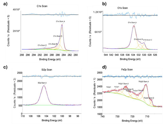
Figure 1.
X-ray photoelectron spectroscopy (XPS) of nanomaterial, the binding energy of Fe/Zeolite@CCNC (1). Scans for (a) C 1s, (b) O 1s, (c) Si 2p, and (d) Fe 2p. Red: data scan; Dark Blue: data fit; Orange and Green: deconvolution analysis; Light Blue: residual plot.
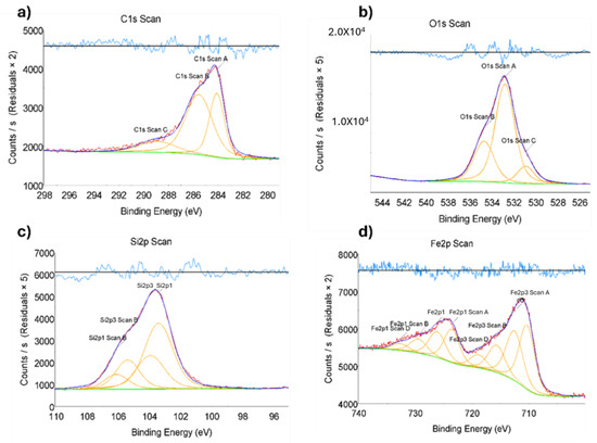
Figure 2.
X-ray photoelectron spectroscopy (XPS) of nanomaterial, the binding energy of Fe/Zeolite@CCNF (2). Scans for (a) C 1s, (b) O 1s, (c) Si 2p, and (d) Fe 2p. Red: data scan; Dark Blue: data fit; Orange and Green: deconvolution analysis; Light Blue: residual plot.
2.2. Morphological Analysis by TEM
The morphology and nanostructure of the synthesized nanocatalyst were thoroughly examined using transmission electron microscopy (TEM). Figure 3a presents a representative TEM image of the nanocatalyst, showing spherical metallic nanoparticles with a size distribution between 10 and 20 nm. Notably, all metallic nanoparticles were observed to be encapsulated within the carbon matrix, with no unbound nanoparticles, a desirable property that prevents the leaching of nanoparticles from the catalyst. This observation is further supported by the control sample presented in Figure 3c, which lacks metallic nanoparticles and consists only of zeolite and nanocellulose nanocrystals that form the carbon matrix.
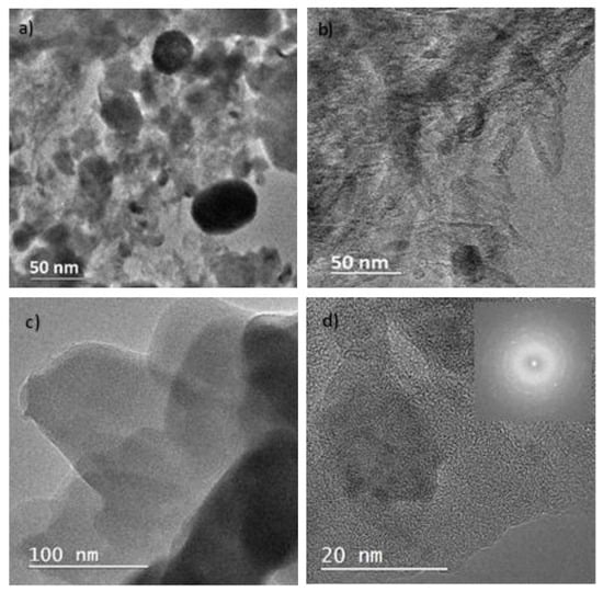
Figure 3.
Transmission electron microscopy (TEM) of (a) Fe/Zeolite@CCNC (1), (b) Fe/Zeolite/CNT@CCNC (3), (c) control sample (nanocellulose + zeolite), and (d) HRTEM of Fe/Zeolite@CCNC (1) along with its diffraction pattern.
Further analysis using high-resolution TEM (HRTEM) was performed to investigate the interconnectivity of the nanocatalyst components. Figure 3d illustrates the presence of a glassy type of carbon that interconnects the metallic nanoparticles within the carbon matrix. The glassy-type carbon was dispersed throughout the entire nanocatalyst with an average size of 2 nm. Finally, Figure 3d provides an HRTEM representation of the Fe/Zeolite@CCNC (1), where clear diffraction lines corresponding to different planes of Fayalite were observed. These results demonstrate the strong interconnection between the zeolite used as a solid support and the metallic nanoparticles generated during the baking process.
Taken together, the TEM and HRTEM observations provide critical insights into the morphology and nanostructure of the synthesized nanocatalyst, revealing a highly interconnected carbon matrix, the absence of free metallic nanoparticles, and the presence of a glassy-type carbon material interconnecting the metallic nanoparticles. These findings provide a foundation for further studies and highlight the potential of this nanocatalyst for electrocatalytic applications.
2.3. Morphological Analysis by SEM
Scanning electron microscopy (SEM) was employed as a characterization technique to gain a more precise understanding of the surface morphology of the synthesized nanomaterial. Figure 4 presents images of the synthesized nanomaterial with a magnification of 50.0 μm, captured using a backscattered electron beam at a potential energy of 10.0 kV. The SEM images reveal the porous structure on the material’s surface for both the nanocellulose nanocrystals and the nanocellulose nanofibrils. The porous structure is a typical feature of this type of carbon matrix, providing the material with strong absorbent properties. Additionally, the SEM images suggest that our nanomaterial exhibits high electrical conductivity. The nanocatalyst’s elemental analysis and color mapping were performed using energy-dispersed X-ray spectroscopy (EDS).
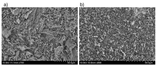
Figure 4.
Scanning electron microscopy (SEM) of (a) Fe/Zeolite@CCNC (1) and (b) Fe/Zeolite@CCNF (2).
2.4. EDS Elemental Analysis and Color Mapping
The results obtained from the energy-dispersive X-ray spectroscopy (EDS) characterization technique are displayed in Figure 5, and are consistent with the qualitative elemental composition obtained by X-ray photoelectron spectroscopy (XPS). The main element present in the sample was carbon, which formed the entire matrix that enclosed the iron particles.
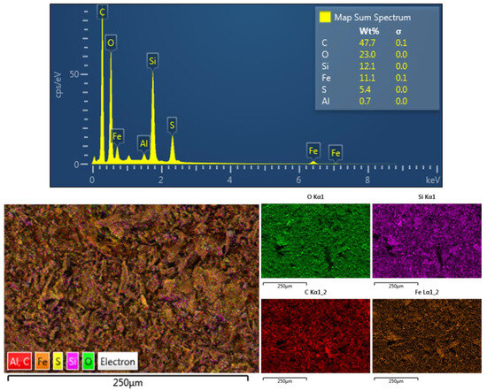
Figure 5.
Elemental analysis and color mapping using energy-dispersive X-ray spectroscopy of Fe/Zeolite@CCNC (1).
The elemental analysis also revealed the presence of metallic iron and iron oxide in varying percentages, as well as silicon and traces of aluminum originating from the initial Zeolite material used in the synthesis process of the nanomaterial. These findings further prove the successful synthesis of the desired nanocatalyst and its chemical composition.
2.5. Analysis of Crystalline Structure by XRD
It is essential to note that the PXRD results provide valuable insights into the crystal structure of the nanomaterial. In this case, the PXRD pattern indicates the presence of zeolite SZM 5, an essential component of the Fe/Zeolite@CCNC (1) material. The orthorhombic crystal system, along with the identified planes (1,1,0) and (5,1,1), suggests the presence of well-ordered zeolite crystals in the sample. Additionally, the signal at 44.9° confirms the presence of metallic iron in a cubic crystal system, with the (0,1,1) plane being the most prominent. Overall, the PXRD results complement the XPS and TEM analyses, providing a more comprehensive picture of the nanomaterial’s elemental structure.
Figure 6 shows the PXRD for the Fe/Zeolite@CCNF (2) nanomaterial, which exhibits the presence of zeolite and iron oxide, specifically hematite and Fayalite. According to Miller’s Index, the signals at 33.7° and 54.9° indicate the presence of hematite in a hexagonal crystal system, with the 1,0,4 and 1,1,6 planes, respectively. Meanwhile, the signals at 34.8° and 35.7° correspond to the presence of Fayalite in an orthorhombic crystal system, with the 3,1,1 and 1,2,1 planes, respectively.
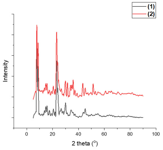
Figure 6.
Powder X-ray diffraction of Fe/Zeolite@CCNC (1) and Fe/Zeolite@CCNF (2).
Iron–aluminum was also detected at approximately 43.0°, consistent with its cubic crystal system. The PXRD results are consistent with those of the other characterization methods in this study, particularly with the interplanar distances observed in HRTEM images. Notably, the two compounds exhibit different iron environments, with both containing a significant amount of Fayalite. The one made from nanocellulose nanocrystal material has higher percentages of hematite and iron–aluminum.
2.6. Raman Analysis
The degree of graphitization and defect level of the as-prepared nanomaterial are investigated using Raman spectroscopic characterization of the nanocatalyst; the resulting findings are shown in Figure 7a,b. The nanocatalyst’s Raman spectra revealed two distinctive peaks at around 1588 cm−1 and 1338 cm−1 for the Fe/Zeolite@CCNC (1) and 1590 cm−1 and 1371 cm−1 for Fe/Zeolite@CCNF (2), which correspond to the G (graphite) and D (defects and disorder) bands, respectively.
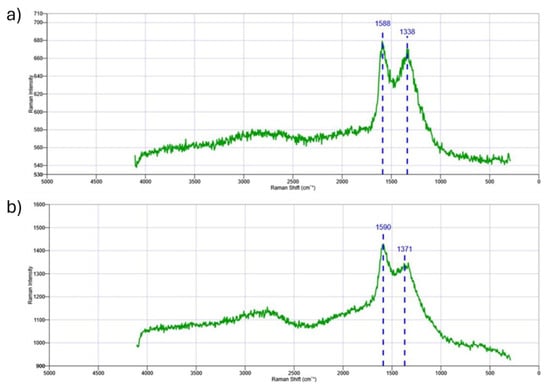
Figure 7.
Raman spectra for (a) Fe/Zeolite@CCNC (1) and (b) Fe/Zeolite@CCNF (2).
The Raman peaks detected in the nanocatalyst are characteristic of carbon-based composites, with the G band representing the E2g vibration mode of sp2-hybridized carbon, and the D band indicating structural disorder or defects in the carbon atoms. The ID/IG ratio is a crucial parameter for evaluating the degree of crystallization of graphitic carbon in the nanocatalyst. A higher ID/IG ratio implies a higher degree of graphitization, whereas a lower ratio indicates a higher number of defect sites. The nanocatalyst’s Raman spectra indicate that the intensity of the D band is lower than that of the G band, suggesting the presence of sp2 hybridized carbon species in the graphitized pore walls. The ID/IG values for Fe/Zeolite@CCNC (1) and Fe/Zeolite@CCNF (2) are 0.98 and 0.95, respectively. These values suggest the formation of high-quality three-dimensional graphitic carbon, comparable to that found in reduced graphene oxide (~1). Therefore, the nanocatalyst exhibits a high degree of graphitization and some levels of defects in its structure, which can potentially enhance its catalytic activity. Between 2500 and 3000 cm−1, 2D and D+G bands are present with a relatively low intensity, which is consistent with the presence of glassy-type carbon material, as mentioned in the TEM analysis.
2.7. Electrochemical Double-Layer Capacitance Studies
Electrochemical double-layer capacitance (EDLC) studies were conducted. They were derived from the capacitive current versus scan rate plot. They were further used to calculate the electrochemical active surface area (ECSA) for all the electrode/electrolyte interface catalysts. The EDLC value for Fe/Zeolite@CCNC (1) is 0.55 mF/cm2; for Fe/Zeolite/CNT@CCNC (3), the value is 0.7 mF/cm2; for Fe/Zeolite@CCNF (2), the value is 0.15 mF/cm2; and for Fe/Zeolite/CNT@CCNF (4), the value is 0.21 mF/cm2, Figure 8. Electrochemical impedance spectroscopy (EIS) was recorded to derive the catalysts’ charge transfer resistance (Rct). Rct values were ~ 207 Ω, 214 Ω,157 Ω, and 186 Ω for (3), (1), (4), and (2), respectively. The scan plots for 1–4 are provided in the Supporting Information Figure S2.
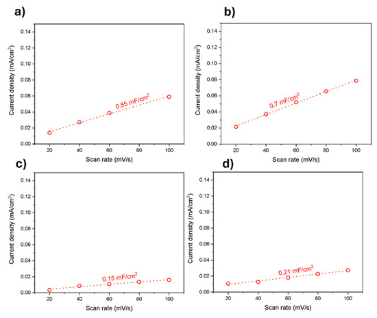
Figure 8.
Electrochemical double-layer capacitance studies of (a) Fe/Zeolite@CCNC (1), (b) Fe/Zeolite/CNT@CCNC (3), (c)Fe/Zeolite@CCNF (2), and (d) Fe/Zeolite/CNT@CCNF (4).
2.8. Catalytic Activity for Oxygen Evolution Reaction (OER)
The Oxygen Evolution Reaction experiment was performed using the four different nanocatalysts previously synthesized: Fe/Zeolite@CCNC (1), Fe/Zeolite@CCNF (2), and the same sets of nanomaterials after the addition of carbon nanotubes, Fe/Zeolite/CNT@CCNC (3) and Fe/Zeolite/CNT@CCNF (4). The potential was swept between −200 and 1100 mV vs. 4 M KCl/Ag/AgCl at a scan rate of 10 mV/s. Figure 9 shows the linear sweep voltammetry for the OER of RuO2, Fe/Zeolite@CCNC (1), Fe/Zeolite@CCNF (2), Fe/Zeolite/CNT@CCNC (3), and Fe/Zeolite/CNT@CCNF (4), determined in a 10 min N2-purged 0.1 M KOH solution at 1600 rpm. The nanocomposite Fe/Zeolite/CNT@CCNC (3) exhibited the highest performance, with an onset potential value of 1.654 V and an overpotential of 551 mV. Table 1 compiles the onset potential for all the nanocomposites 1–4, and the calculated overpotential at 10 mA/cm2 with respect to the theoretical potential of OER. Interestingly, the addition of CNT to the samples caused an increase in OER performance for composites (1) and (2), but more prominently for (2). The beneficial effect of CNTs in improving OER performance in nanocomposites has been reported before [33,34]. The reasons for the strong enhancement that the CNTs showed in (2) have yet to be determined. However, we think that they increased the electronic accessibility to the Fe-sites on the composite, leading to a higher OER performance.
Figure 9.
OER polarization of commercial powder RuO2, Fe/Zeolite@CCNC (1), Fe/Zeolite@CCNF (2), Fe/Zeolite/CNT@CCNC (3), and Fe/Zeolite/CNT@CCNF (4) catalysts in 0.1M KOH at 1600 rpm.

Table 1.
OER onset potentials and overpotentials to reach 10 mA/cm2 for RuO2, Fe/Zeolite@CCNC (1), Fe/Zeolite@CCNF (2), Fe/Zeolite/CNT@CCNC (3), and Fe/Zeolite/CNT@CCNF(4) catalysts.
The OER performance of the nanocomposites was compared with previously reported electrocatalysts, and this is shown in Table 2.
Table 2.
Comparison of OER performances with previously reported electrocatalysts.
2.9. Chronoamperometry Measurement and Performance Comparison
The stability of the Fe/Zeolite/CNT@CCNC (3) was assessed through a Chronoamperometry experiment over 24 h using a glassy carbon working electrode, a platinum counter electrode, and a 3 M Ag/AgCl reference electrode. A 0.1M KOH solution served as the electrolyte for the experiment. A 20 μL of the sample was drop-casted onto the working electrode surface and allowed to dry at room temperature. The potential was maintained at 1.75 V vs. RHE. The constant potential was used throughout the test. The current density was measured over time and expressed as a percentage of its initial value. A decrease in current density occurred within the first 2 h, indicating a decline in performance under the applied OER potential and the alkaline conditions. After this initial drop, the current stabilized with some residual, non-zero activity, as shown in Figure 10. These findings suggest that the catalyst’s core structure has a practical operational lifetime of two hours under the applied OER potential and alkaline conditions.
Figure 10.
Chronoamperometry measurement of Fe/Zeolite/CNT@CCNC (3) at 1.75V vs. RHE.
2.10. BET Surface Area Analysis
The specific surface areas of Fe/Zeolite@CCNC (1) and Fe/Zeolite@CCNF (2) were assessed using a HORIBA SA-9600 series multipoint BET Analyzer (Kyoto, Japan). Both samples were degassed at 300 °C for 240 min to ensure the effective removal of adsorbed gases without compromising the stability of the materials. BET specific surface area measurements were carried out using three-point nitrogen adsorption at relative concentrations of 4.9%, 14.5%, and 28.5%. Surface area calculations were performed with the integrated software of the HORIBA SA-9600 multipoint BET Analyzer, which uses the multipoint Brunauer–Emmett–Teller model. The Fe/Zeolite@CCNC (1) had a specific surface area of 301.47 m2/g. Fe/Zeolite@CCNF (2) had a specific surface area of 120.39 m2/g. The higher surface area of Fe/Zeolite@CCNC (1) indicates that it is more porous than Fe/Zeolite@CCNF (2). The higher electrochemical activity of Fe/Zeolite@CCNC (1) correlates with its higher porosity and appears to be a contributing factor, making the active Fe sites more accessible within the pore network. However, there may be other influential components derived from the crystalline form of nanocellulose that were transferred to the final bionanocarbon composite. The Supplementary File contains the BET surface data analysis for nanocomposites.
3. Materials and Methods
3.1. Materials
All chemicals were used as received without further purification. The following chemicals were used to prepare the Nanocellulose-Zeolite-Fe nanocomposite. The Zeolite ZSM-5 (400 m2/g, in a mole ratio of 30:1 SiO2:Al2O3) was purchased from Alfa Aesar, Ward Hill, MA, USA; iron sulfate hexahydrate (FeSO4.7H2O) (ACS reagent, ≥99.0%) was purchased from Sigma-Aldrich, Saint Louis, MO, USA; the nanocellulose materials were produced at the USDA Forest Service Forest Products Laboratory (FPL), Madison, WI, USA. Deionized (DI) water (>18.20 MI cm resistivity) was obtained from the Milli-Q® instrument (Millipore Corporation, Burlington, MA, USA).
3.2. Production of Cellulose Nanomaterials
Cellulose nanocrystals and cellulose nanofibrils were produced at pilot scale at FPL, and the procedures are described in detail elsewhere [42,43]. Briefly, CNCs were prepared through the sulfuric acid hydrolysis of commercial softwood prehydrolysis Kraft dissolving pulp, and the CNFs were produced via TEMPO (2,2,6,6-Tetramethylpiperidin-1-yl)oxyl) oxidation of bleached Kraft Eucalyptus at pH 10 [44].
3.3. Synthesis of Fe/Zeolite@CCNC (1)
A total of 1.00 g of FeSO4 was added to a 20 mL beaker. 6H2O was dissolved in the minimum volume of DI water (~5 mL). To this solution, 1.00 g of Zeolite was added, and the suspension was stirred for 5 min. Afterward, 8.00 g of nanocellulose nanocrystals was added to the suspension. The mixture was stirred with a spatula until a paste was formed. The mixture was lyophilized for 24 h. The obtained white-green foam was carbonized in a furnace at 800 °C under argon gas flow for 3 h at a heating rate of 5 °C/min. The black product was removed from the furnace to cool down to room temperature and kept in a glass vial for further use.
3.4. Synthesis of Fe/Zeolite@CCNF (2)
The composite was prepared as in (1) but using nanocellulose nanofibrils instead of nanocellulose nanocrystals.
3.5. Synthesis of Fe/Zeolite/CNT@CCNC (3)
The black powder obtained in (1) was mixed with 500 mg of multiwall carbon nanotubes using a mortar and pestle for 1 h.
3.6. Synthesis of Fe/Zeolite/CNT@CCNF (4)
The black powder obtained in (2) was mixed with 500 mg of multiwall carbon nanotubes using a mortar and pestle for 1 h.
3.7. Characterization of the Materials
The synthesized nanomaterial was characterized in a Bruker D8 Discover X-ray Diffractometer to obtain the powder X-ray diffraction (PXRD) patterns. The morphologies, microstructures, and elemental composition of the nanocatalyst were analyzed using transmission electron microscopy (TEM, Model: Hitachi H-7650, Tokyo, Japan) and scanning electron microscopy (SEM, Model: Hitachi SU-3500, Tokyo, Japan) equipped with energy-dispersive X-ray spectroscopy (EDS) instruments. Elemental analysis color mapping was performed using backscattering electron imaging. The XPS characterization was performed using a Thermo Fisher Scientific instrument (Waltham, MA, USA), K alpha+, equipped with an Al anode, the charge compensation was performed with an Argon flood gun, and the chamber pressure was kept in the range 0.5–1 × 10⁻⁸ mBar.
3.8. OER Experimental Methods
RuO2, Fe/Zeolite@CCNC (1), Fe/Zeolite@CCNF (2), Fe/Zeolite/CNT@CCNC(3), and Fe/Zeolite/CNT@CCNF (4) catalyst inks were prepared by mixing 1 mg of the catalytic material with a mixture 1:1:3:0.1 of DIwater: Isopropanol: Ethanol: Nafion® solution. The mixtures were homogenized under ultrasound for 1 h. Afterward, the prepared inks were added to a cleaned glassy carbon electrode, loading approximately 0.3 and 1 mg/cm2 of commercial RuO2 and iron-based catalysts, respectively. Then, the modified electrodes were dried at room temperature for 30 min. OER electrochemical tests were completed by running the inked glassy carbon electrode in a 10 min N2-purged 0.1 M KOH solution at 1600 rpm. The potential was swept between −200 and 1100 mV vs. 4 M KCl/Ag/AgCl at a scan rate of 10 mV/s. OER electrochemical tests were performed using the rotating electrode method.
3.9. Chronoamperometry Method
The chronoamperometry experiment was conducted over 20 h using a glassy carbon working electrode, a platinum counter electrode, and a 3 M Ag/AgCl reference electrode. A 0.1 M KOH solution served as the electrolyte for the experiment. A 20 μL sample was drop-casted onto the working electrode surface and allowed to dry at room temperature. The potential was maintained at 1.75 V vs. RHE. The constant potential was used throughout the test. The current density was measured over time.
3.10. Electrochemical Double-Layer Capacitance Studies
Electrochemical double-layer capacitance (EDLC) studies were conducted following established reported methods [45].
3.11. BET Surface Area Analysis
The HORIBA SA-9600 series multipoint BET Analyzer was used to carry out the BET surface area analysis. This instrument supports a specific surface measurement range of approximately 0.01 to 2000 m2/g. The system operates based on the static volumetric adsorption method. The samples were degassed at 300 °C for 240 min to ensure the effective removal of adsorbed gases. BET specific surface area measurements were carried out using three-point nitrogen adsorption at relative concentrations of 4.9%, 14.5%, and 28.5%. Surface area calculations were performed with the integrated software of the HORIBA SA-9600 multipoint BET Analyzer, which uses the multipoint Brunauer–Emmett–Teller model.
4. Conclusions
Our study presents a new class of highly efficient nanocatalysts for the electrochemical water oxidation reaction. Using biocarbon derived from nanocellulose and incorporating Fe–zeolite and CNTs in the composite significantly improved the catalytic activity of the nanomaterial. Our findings demonstrate that the composite derived from nanocellulose nanocrystals and CNT exhibits the highest catalytic activity for OER, with an onset potential close to that of the reference material RuO2, but with an even lower overpotential, at 10 mA/cm2.
The synthesis of our nanocatalysts is straightforward and environmentally friendly, using low-cost and abundant iron compared to precious metals such as Ru, Ir, and Pt, which makes this material an economical alternative for performing OER. The thorough characterization of the nanomaterials using advanced spectroscopic techniques, including TEM, SEM-EDS, PXRD, and XPS, provides insight into the structural and chemical properties of the composite, further contributing to the understanding of the catalytic activity of these materials.
Our results suggest that using biocarbon and incorporating CNTs into the nanocomposite can enhance conductivity and improve the connection between metallic particles, resulting in higher electrocatalytic activity for OER. These findings pave the way for further investigations into the design and development of biocarbon-based nanocatalysts for various energy and electrochemical applications. Overall, our study offers valuable insights into the development of efficient, low-cost, and sustainable catalysts for OER, a crucial step toward achieving a sustainable energy future.
Supplementary Materials
The following supporting information can be downloaded at: https://www.mdpi.com/article/10.3390/catal15080719/s1. The supplementary information contains BET data and scan rates for nanocomposites 1–4. Table S1: BET Specific Surface Area of 1 and 2; Figure S1: BET-specific surface area plot for 1 and 2. Figure S2: Scan rate plots for 1–4.
Author Contributions
Conceptualization, J.C.N.; methodology, J.H.-O. and C.R.C.; validation, J.H.-O., R.C.S. and C.R.C.; formal analysis, J.H.-O., C.A., A.M., L.E.S.C., B.A.T. and C.R.C.; investigation, J.H.-O. and R.C.S.; resources, J.C.N. and C.R.C.; writing—original draft preparation, J.H.-O. and J.C.N.; writing—review and editing, J.C.N., R.C.S. and C.R.C.; supervision, J.C.N.; project administration, J.C.N.; funding acquisition, J.C.N., C.R.C. and R.C.S. All authors have read and agreed to the published version of the manuscript.
Funding
This research was supported in part by the US Department of Agriculture. The authors thank Richard Reiner, USDA Forest Service, Forest Products Laboratory, USDA National Institute of Food and Agriculture (NIFA) 2023-67021-39826, and the US Endowment for Forestry and Communities. Financial support from USDA NIFA 2019–38422–30214, and the Ralph & Kathleen Ponce de Leon Endowment are gratefully acknowledged. C.R.C. acknowledges the Center for alkaline-based Energy Solutions (CABES), an Energy Frontier Research Center funded by the U.S. Department of Energy (DOE), Office of Science, Basic Energy Sciences (BES), under Award # DESC0019445.
Data Availability Statement
Data available upon request.
Acknowledgments
We thank the laboratory members of the C.R.C. group and the supportive staff of the College of Engineering from UTEP for their technical support.
Conflicts of Interest
The authors declare no conflicts of interest.
References
- Tahir, M.; Pan, L.; Idrees, F.; Zhang, X.; Wang, L.; Zou, J.-J.; Wang, Z.L. Electrocatalytic oxygen evolution reaction for energy conversion and storage: A comprehensive review. Nano Energy 2017, 37, 136–157. [Google Scholar] [CrossRef]
- Kim, J.S.; Kim, B.; Kim, H.; Kang, K. Recent Progress on Multimetal Oxide Catalysts for the Oxygen Evolution Reaction. Adv. Energy Mater. 2018, 8. [Google Scholar] [CrossRef]
- Fabbri, E.; Schmidt, T.J. Oxygen Evolution Reaction—The Enigma in Water Electrolysis. ACS Catal. 2018, 8, 9765–9774. [Google Scholar] [CrossRef]
- Wu, Z.P.; Lu, X.F.; Zang, S.Q.; Lou, X.W. Non-noble-metal-based electrocatalysts toward the oxygen evolution reaction. Adv. Funct. Mater. 2020, 30, 1910274. [Google Scholar] [CrossRef]
- Zhu, Y.; Tahini, H.A.; Hu, Z.; Chen, Z.; Zhou, W.; Komarek, A.C.; Lin, Q.; Lin, H.; Chen, C.; Zhong, Y.; et al. Boosting Oxygen Evolution Reaction by Creating Both Metal Ion and Lattice-Oxygen Active Sites in a Complex Oxide. Adv. Mater. 2019, 32, e1905025. [Google Scholar] [CrossRef]
- Zhuang, L.; Ge, L.; Yang, Y.; Li, M.; Jia, Y.; Yao, X.; Zhu, Z. Ultrathin Iron-Cobalt Oxide Nanosheets with Abundant Oxygen Vacancies for the Oxygen Evolution Reaction. Adv. Mater. 2017, 29. [Google Scholar] [CrossRef]
- Xu, H.; Shang, H.; Wang, C.; Jin, L.; Chen, C.; Wang, C.; Du, Y. Three-dimensional open CoMoOx/CoMoSx/CoSx nanobox electrocatalysts for efficient oxygen evolution reaction. Appl. Catal. B: Environ. 2020, 265. [Google Scholar] [CrossRef]
- Wang, X.; Dong, L.; Qiao, M.; Tang, Y.; Liu, J.; Li, Y.; Li, S.; Su, J.; Lan, Y. Exploring the Performance Improvement of the Oxygen Evolution Reaction in a Stable Bimetal–Organic Framework System. Angew. Chem. Int. Ed. Engl. 2018, 57, 9660–9664. [Google Scholar] [CrossRef]
- Feng, C.; Faheem, M.B.; Fu, J.; Xiao, Y.; Li, C.; Li, Y. Fe-Based Electrocatalysts for Oxygen Evolution Reaction: Progress and Perspectives. ACS Catal. 2020, 10, 4019–4047. [Google Scholar] [CrossRef]
- Suen, N.-T.; Hung, S.-F.; Quan, Q.; Zhang, N.; Xu, Y.-J.; Chen, H.M. Electrocatalysis for the oxygen evolution reaction: Recent development and future perspectives. Chem. Soc. Rev. 2017, 46, 337–365. [Google Scholar] [CrossRef]
- Song, F.; Busch, M.M.; Lassalle-Kaiser, B.; Hsu, C.-S.; Petkucheva, E.; Bensimon, M.; Chen, H.M.; Corminboeuf, C.; Hu, X. An Unconventional Iron Nickel Catalyst for the Oxygen Evolution Reaction. ACS Central Sci. 2019, 5, 558–568. [Google Scholar] [CrossRef]
- Divanis, S.; Kutlusoy, T.; Boye, I.M.I.; Man, I.C.; Rossmeisl, J. Oxygen evolution reaction: A perspective on a decade of atomic scale simulations. Chem. Sci. 2020, 11, 2943–2950. [Google Scholar] [CrossRef] [PubMed]
- Zhang, J.; Zhao, Z.; Xia, Z.; Dai, L. A metal-free bifunctional electrocatalyst for oxygen reduction and oxygen evolution reactions. Nat. Nanotechnol. 2015, 10, 444–452. [Google Scholar] [CrossRef] [PubMed]
- Wang, H.-F.; Chen, L.; Pang, H.; Kaskel, S.; Xu, Q. MOF-derived electrocatalysts for oxygen reduction, oxygen evolution and hydrogen evolution reactions. Chem. Soc. Rev. 2020, 49, 1414–1448. [Google Scholar] [CrossRef] [PubMed]
- Xue, Z.; Liu, K.; Liu, Q.; Li, Y.; Li, M.; Su, C.-Y.; Ogiwara, N.; Kobayashi, H.; Kitagawa, H.; Liu, M.; et al. Missing-linker metal-organic frameworks for oxygen evolution reaction. Nat. Commun. 2019, 10, 1–8. [Google Scholar] [CrossRef]
- Xu, L.; Jiang, Q.; Xiao, Z.; Li, X.; Huo, J.; Wang, S.; Dai, L. Plasma-engraved Co3O4 nanosheets with oxygen vacancies and high surface area for the oxygen evolution reaction. Angew. Chem. Int. Ed. 2016, 55, 5277–5281. [Google Scholar] [CrossRef]
- McCrory, C.C.L.; Jung, S.; Peters, J.C.; Jaramillo, T.F. Benchmarking Heterogeneous Electrocatalysts for the Oxygen Evolution Reaction. J. Am. Chem. Soc. 2013, 135, 16977–16987. [Google Scholar] [CrossRef]
- Fabbri, E.; Habereder, A.; Waltar, K.; Kötz, R.; Schmidt, T.J. Developments and perspectives of oxide-based catalysts for the oxygen evolution reaction. Catal. Sci. Technol. 2014, 4, 3800–3821. [Google Scholar] [CrossRef]
- Habibi, Y.; Lucia, L.A.; Rojas, O.J. Cellulose nanocrystals: Chemistry, selfassembly, and applications. Chem. Rev. 2010, 110, 3479–3500. [Google Scholar] [CrossRef]
- De Souza Lima, M.M.; Borsali, R. Rodlike Cellulose Microcrystals: Structure, Properties, and Applications. Macromol. Rapid Commun. 2004, 25, 771–787. [Google Scholar] [CrossRef]
- Siqueira, G.; Abdillahi, H.; Bras, J.; Dufresne, A. High reinforcing capability cellulose nanocrystals extracted from Syngonanthus nitens (Capim Dourado). Cellulose 2009, 17, 289–298. [Google Scholar] [CrossRef]
- Batista, M.D.R.; Drzal, L.T. Carbon fiber/epoxy matrix composite interphases modified with cellulose nanocrystals. Compo. Sci. Technol. 2018, 164, 274–281. [Google Scholar] [CrossRef]
- Li, Z.; Yao, C.; Wang, F.; Cai, Z.; Wang, X. Cellulose nanofiber-templated three-dimension TiO2 hierarchical nanowire network for photoelectrochemical photoanode. Nanotechnology 2014, 25, 504005. [Google Scholar] [CrossRef] [PubMed]
- Li, Z.; Yao, C.; Yu, Y.; Cai, Z.; Wang, X. Highly Efficient Capillary Photoelectrochemical Water Splitting Using Cellulose Nanofiber-Templated TiO2 Photoanodes. Adv. Mater. 2014, 26, 2262–2267. [Google Scholar] [CrossRef] [PubMed]
- Li, Z.; Yao, C.; Wang, Y.-C.; Mikael, S.; Gunasekaran, S.; Ma, Z.; Cai, Z.; Wang, X. High-density platinum nanoparticle-decorated titanium dioxide nanofiber networks for efficient capillary photocatalytic hydrogen generation. J. Mater. Chem. A 2016, 4, 11672–11679. [Google Scholar] [CrossRef]
- Nair, S.S.; Chen, J.; Slabon, A.; Mathew, A.P. Converting cellulose nanocrystals into photocatalysts by functionalisation with titanium dioxide nanorods and gold nanocrystals. RSC Adv. 2020, 10, 37374–37381. [Google Scholar] [CrossRef]
- Yoon, S.H.; Jin, H.-J.; Kook, M.-C.; Pyun, Y.R. Electrically Conductive Bacterial Cellulose by Incorporation of Carbon Nanotubes. Biomacromolecules 2006, 7, 1280–1284. [Google Scholar] [CrossRef]
- He, Z.; Jiang, Y.; Sun, D.; Dai, L.; Wang, H. Advanced LiTi2(PO4)3/C anode by incorporation of carbon nanotubes for aqueous lithium-ion batteries. Ionics 2017, 23, 575–583. [Google Scholar] [CrossRef]
- MacDonald, R.A.; Voge, C.M.; Kariolis, M.; Stegemann, J.P. Carbon nanotubes increase the electrical conductivity of fibroblast-seeded collagen hydrogels. Acta Biomater. 2008, 4, 1583–1592. [Google Scholar] [CrossRef]
- Gökçeli, G.; Karatepe, N. Improving the properties of indium tin oxide thin films by the incorporation of carbon nanotubes with solution-based techniques. Thin Solid Films 2020, 697, 137844. [Google Scholar] [CrossRef]
- Jiang, X.; Drzal, L.T. Improving electrical conductivity and mechanical properties of high density polyethylene through incorporation of paraffin wax coated exfoliated graphene nanoplatelets and multi-wall carbon nano-tubes. Compos. Part A: Appl. Sci. Manuf. 2011, 42, 1840–1849. [Google Scholar] [CrossRef]
- Duongthipthewa, A.; Su, Y.; Zhou, L. Electrical conductivity and mechanical property improvement by low-temperature carbon nanotube growth on carbon fiber fabric with nanofiller incorporation. Compos. Part B: Eng. 2020, 182. [Google Scholar] [CrossRef]
- Gao, R.; Dai, Q.; Du, F.; Yan, D.; Dai, L. C60-adsorbed single-walled carbon nanotubes as metal-free, pH-universal, and multifunctional catalysts for oxygen reduction, oxygen evolution, and hydrogen evolution. J. Am. Chem. Soc. 2019, 141, 11658–11666. [Google Scholar] [CrossRef] [PubMed]
- Peng, X.; Pi, C.; Zhang, X.; Li, S.; Huo, K.; Chu, P.K. Recent progress of transition metal nitrides for efficient electrocatalytic water splitting. Sustain. Energy Fuels 2018, 3, 366–381. [Google Scholar] [CrossRef]
- Leal-Rodríguez, C.; Rodríguez-Padrón, D.; Alothman, Z.A.; Cano, M.; Giner-Casares, J.J.; Muñoz-Batista, M.J.; Osman, S.M.; Luque, R. Thermal and light irradiation effects on the electrocatalytic performance of hemoglobin modified Co3O4-g-C3N4 nanomaterials for the oxygen evolution reaction. Nanoscale 2020, 12, 8477–8484. [Google Scholar] [CrossRef]
- De Silva, U.; Masud, J.; Zhang, N.; Hong, Y.; Liyanage, W.P.R.; Zaeem, M.A.; Nath, M. Nickel telluride as a bifunctional electrocatalyst for efficient water splitting in alkaline medium. J. Mater. Chem. A 2018, 6, 7608–7622. [Google Scholar] [CrossRef]
- Wu, X.; Han, S.; He, D.; Yu, C.; Lei, C.; Liu, W.; Zheng, G.; Zhang, X.; Lei, L. Metal Organic Framework Derived Fe-Doped CoSe2 Incorporated in Nitrogen-Doped Carbon Hybrid for Efficient Hydrogen Evolution. ACS Sustain. Chem. Eng. 2018, 6, 8672–8678. [Google Scholar] [CrossRef]
- Cheng, N.; Liu, Q.; Tian, J.; Xue, Y.; Asiri, A.M.; Jiang, H.; He, Y.; Sun, X. Acidically oxidized carbon cloth: A novel metal-free oxygen evolution electrode with high catalytic activity. Chem. Commun. 2014, 51, 1616–1619. [Google Scholar] [CrossRef]
- Tian, J.; Liu, Q.; Asiri, A.M.; Alamry, K.A.; Sun, X. Ultrathin Graphitic C3N4 Nanosheets/Graphene Composites: Efficient Organic Electrocatalyst for Oxygen Evolution Reaction. ChemSusChem 2014, 7, 2125–2130. [Google Scholar] [CrossRef]
- Wang, Q.; Ji, Y.; Lei, Y.; Wang, Y.; Wang, Y.; Li, Y.; Wang, S. Pyridinic-N-Dominated Doped Defective Graphene as a Superior Oxygen Electrocatalyst for Ultrahigh-Energy-Density Zn–Air Batteries. ACS Energy Lett. 2018, 3, 1183–1191. [Google Scholar] [CrossRef]
- Qian, Y.; Hu, Z.; Ge, X.; Yang, S.; Peng, Y.; Kang, Z.; Liu, Z.; Lee, J.Y.; Zhao, D. A metal-free ORR/OER bifunctional electrocatalyst derived from metal-organic frameworks for rechargeable Zn-Air batteries. Carbon 2017, 111, 641–650. [Google Scholar] [CrossRef]
- Reiner, R.S.; Rudie, A.W. Process Scale-Up of Cellulose Nanocrystal Production to 25 kg per Batch at the Forest Products Laboratory. In Production and Application of Cellulose Nanomaterials; TAPPI Press: Peachtree Corners, GA, USA, 2013; pp. 21–24. [Google Scholar]
- Reiner, R.S.; Rudie, A.W. Experiences with scaling-up production of TEMPO-grade cellulose nanofibrils. In Nanocelluloses: Their Preparation, Properties, and Applications; American Chemical Society: Washington, DC, USA, 2017; pp. 227–245. [Google Scholar]
- Saito, T.; Kimura, S.; Nishiyama, Y.; Isogai, A. Cellulose Nanofibers Prepared by TEMPO-Mediated Oxidation of Native Cellulose. Biomacromolecules 2007, 8, 2485–2491. [Google Scholar] [CrossRef]
- Stoller, M.D.; Ruoff, R.S. Best practices for determining the specific capacitance of materials for electrochemical capacitors. Energy Environ. Sci. 2010, 3, 1294–1301. [Google Scholar] [CrossRef]
Disclaimer/Publisher’s Note: The statements, opinions and data contained in all publications are solely those of the individual author(s) and contributor(s) and not of MDPI and/or the editor(s). MDPI and/or the editor(s) disclaim responsibility for any injury to people or property resulting from any ideas, methods, instructions or products referred to in the content. |
© 2025 by the authors. Licensee MDPI, Basel, Switzerland. This article is an open access article distributed under the terms and conditions of the Creative Commons Attribution (CC BY) license (https://creativecommons.org/licenses/by/4.0/).