Article

Fabrication of CoP@P, N-CNTs-Deposited Nickel Foam for Energy-Efficient Hydrogen Generation via Electrocatalytic Urea Oxidation

by
Hany M. Youssef
,
Maged N. Shaddad
*,
Saba A. Aladeemy
* and
Abdullah M. Aldawsari
Department of Chemistry, College of Science and Humanities, Prince Satam bin Abdulaziz University, P.O. Box 173, Al-Kharj 11942, Saudi Arabia
*
Authors to whom correspondence should be addressed.
Catalysts 2025, 15(7), 652; https://doi.org/10.3390/catal15070652
Submission received: 21 April 2025 / Revised: 30 June 2025 / Accepted: 1 July 2025 / Published: 4 July 2025

Abstract

The simultaneous generation of hydrogen fuel and wastewater remediation via electrocatalytic urea oxidation has emerged as a promising approach for sustainable energy and environmental solutions. However, the practical application of this process is hindered by the limited active sites and high charge-transfer resistance of conventional anode materials. In this work, we introduce a novel CoP@P, N-CNTs/NF electrocatalyst, fabricated through a facile one-step thermal annealing technique. Comprehensive characterizations confirm the successful integration of CoP nanoparticles and phosphorus/nitrogen co-doped carbon nanotubes (P, N-CNTs) onto nickel foam, yielding a unique hierarchical structure that offers abundant active sites and accelerated electron transport. As a result, the CoP@P, N-CNTs/NF electrode achieves outstanding urea oxidation reaction (UOR) performance, delivering current densities of 158.5 mA cm−2 at 1.5 V and 232.95 mA cm−2 at 1.6 V versus RHE, along with exceptional operational stability exceeding 50 h with negligible performance loss. This innovative, multi-element-doped electrode design marks a significant advancement in the field, enabling highly efficient UOR and energy-efficient hydrogen production. Our approach paves the way for scalable, cost-effective solutions that couple renewable energy generation with effective wastewater treatment.

1. Introduction

The demand for renewable energy is more urgent as the Earth confronts environmental degradation and a growing dependence on finite fossil resources [1,2,3]. Hydrogen, as a clean and renewable energy carrier, has become fundamental in the shift toward sustainable energy systems [4,5,6]. Among the numerous techniques for hydrogen production, water electrolysis is distinguished as an eco-friendly and scalable alternative [5,7,8]. Nonetheless, its extensive application is constrained by the slow kinetics of the oxygen evolution reaction (OER) at the anode [9,10], which considerably elevates the energy demands of the process [11,12,13,14]. To address this difficulty, the urea oxidation reaction (UOR) has been suggested as a substitute anodic reaction, presenting numerous benefits compared to the oxygen evolution reaction (OER) [15,16,17]. The urea oxidation reaction (UOR) is thermodynamically advantageous, necessitating a reduced overpotential, while concurrently mitigating environmental issues by processing urea-laden wastewater, a consequence of diverse industrial and agricultural operations [17,18,19,20,21].
In the UOR process [22,23,24,25,26,27,28], the application of an electrical potential generates the simultaneous oxidation of urea at the anode and the cathode, respectively. The anodic reaction Equation (1) produces nitrogen (N2) and carbon dioxide (CO2), while the cathodic hydrogen evolution reaction (HER, Equation (2)) yields hydrogen (H2). The primary products of urea electrooxidation employing nickel-based catalysts are N2 and CO2 gases, corresponding to the complete six-electron oxidation pathway. Nevertheless, comprehensive product analysis by Hopsort et al. [29] demonstrated the formation of several intermediate and side products during urea electrooxidation over Ni(II)/Ni(III) redox-active catalysts, with cyanate (OCN), ammonium (NH4+), carbonate (CO32−), and nitrite (NO2) ions as secondary products, albeit typically present in trace concentrations. These findings indicate that the urea oxidation mechanism involves multiple reaction pathways, with incomplete oxidation routes contributing to the formation of nitrogen- and carbon-containing intermediates alongside the desired complete mineralization products. The thermodynamic oxidation potential for UOR (0.37 V vs. RHE) is significantly lower than that required for conventional water electrolysis (1.23 V vs. RHE). This substantial reduction in energy requirements (approximately 70%) renders urea electrolysis an economically advantageous approach for hydrogen production compared to conventional water electrolysis systems [18,30].
Anodic reaction: CO(NH2)2 + 6OH → N2 + CO2 + 5H2O + 6e
Cathodic reaction: 6H2O + 6e → 3H2 + 6OH
Transition noble-free electrocatalysts have attracted considerable interest in urea oxidation reaction (UOR) owing to their availability, economic viability, and enhanced catalytic performance [31,32,33,34]. Cobalt (Co) and nickel (Ni) are distinguished by their remarkable electrochemical characteristics [35,36,37]. Despite the prevalent implementation of nickel-based catalysts in urea electrolysis systems, a significant limitation persists in that conventional synthesis methodologies often entail sophisticated and multifaceted procedures, thereby restricting the practical deployment of these electrocatalytic materials. Thus, there exists a critical need to develop streamlined approaches for nickel foam modification that preserve structural integrity while simultaneously addressing economic viability, energy efficiency, and performance optimization parameters [38,39,40,41,42].
Nickel foam (NF) has demonstrated itself as an optimal substrate for catalyst deposition due to its substantial surface area, superior electrical conductivity, and formidable mechanical strength. These attributes render it a multifaceted platform for the advancement of sophisticated electrocatalysts [43]. As reported by Yan et al. [44], they synthesized hierarchical NiCo LDH/NiCo(OH)2 microspheres composed of ultrathin nanosheets on nickel foam via the solution method. The electrocatalyst exhibits exceptional activity with a low onset potential of 0.29 V vs. Hg/HgO, primarily attributed to the abundant NiCo LDH-NiCo(OH)2 interfacial sites and beneficial bimetallic electronic effects in the catalyst architecture. Wang et al. [45] developed cobalt-doped Ni3S4-NiS/Ni nanomaterials for urea oxidation applications. The optimized electrode exhibited excellent UOR activity with a potential of 1.350 V vs. RHE at 10 mA cm−2. When configured in a cobalt-doped Ni3S4-NiS/Ni/AC device architecture, the system demonstrated superior energy and power densities along with robust cyclability, maintaining 87.27% performance retention after 3000 cycles.
Recent investigations into nickel-based electrocatalysts have revealed significant challenges regarding their electrochemical performance, notably excessive overpotential requirements and limited operational stability [46]. To address these inherent limitations, significant advances have been achieved through strategic materials engineering approaches. Recent research has concentrated on doping techniques and structural alterations to improve the efficacy of transition metal-based catalysts [47,48,49,50,51]. These design strategies have demonstrably enhanced catalytic activity by reducing overpotential requirements while simultaneously improving reaction kinetics and long-term operational stability during urea electrolysis [19].
Nitrogen (N) doping is acknowledged as an effective method to enhance catalytic activity by modifying the electronic structure, augmenting the density of active sites, and improving overall conductivity [48]. The integration of phosphorus (P) into the catalyst enhances its efficacy by promoting electron transport and stabilizing the catalytic substance [52]. Moreover, carbon (C) doping enhances structural flexibility and further elevates conductivity, thus augmenting the catalyst’s efficiency and durability [50,53]. These adjustments together improve the electrochemical characteristics of the material, rendering it very efficient for UOR and, consequently, hydrogen production. For instance, Yan et al. [54] developed a scalable method for the in situ growth of Ni2P/Fe2P nanohybrids on nickel foam (Ni2P/Fe2P/NF) as a bifunctional electrode for urea electrolysis. This electrode demonstrates superior electrocatalytic performance, requiring only 115 mV overpotential for HER and 1.36 V for UOR at 10 mA cm−2. When configured in a complete electrolyzer, the system achieves remarkable efficiency with a cell voltage of just 1.47 V at 10 mA cm−2. Cheng et al. [36] synthesized CoN/Ni(OH)2 heterocatalysts on nickel foam, demonstrating exceptional bifunctional performance for both HER and UOR applications. The optimized catalyst exhibited superior HER activity (40 mV overpotential at 10 mA cm−2, Tafel slope of 48 mV dec−1) and excellent UOR performance (1.39 V at 50 mA cm−2, Tafel slope of 64 mV dec−1). A two-electrode electrolyzer utilizing this bifunctional catalyst achieved efficient urea electrolysis with a remarkably low cell voltage of 1.43 V at 10 mA cm−2 while maintaining operational stability, representing a significant advancement in simultaneous hydrogen production and urea-rich wastewater remediation. A study by Qian et al. [55] synthesized Ni@C−V2O3/NF heterostructures featuring V2O3 nanosheets on N-doped, carbon-encapsulated nickel for bifunctional electrocatalysis. This material exhibits exceptional UOR performance (1.32–1.43 V at 10–1000 mA cm−2) and HER activity (36–355 mV overpotentials at 10–1000 mA cm−2) with outstanding 72 h stability at 100 mA cm−2. These superior properties are derived from the synergistic effects between Ni and V2O3, the protective N-doped carbon layer, and the hierarchical nanosheet architecture on NF.
This study investigates the development of a CoP@P, N-CNTs-coated nickel foam electrocatalyst aimed at enhancing energy-efficient hydrogen production via electrocatalytic urea oxidation. The distinctive design integrates the catalytic advantages of Co and Ni with the electrical and structural enhancements provided by N and P co-doping on CNTs. Nickel foam serves as the optimal substrate, ensuring maximum catalyst loading and electrical conductivity. The CoP@P, N-CNTs/NF electrode consists of phosphorus and nitrogen co-doped carbon nanotubes with a cobalt phosphide shell layer on nickel foam, ensuring exceptional conformal coverage. The CoP@P, N-CNTs/NF electrode has outstanding UOR performance, achieving 158.5 mA cm−2 at 1.5 V versus RHE and 232.95 mA cm−2 at 1.6 V relative to RHE. Moreover, it demonstrates exceptional long-term stability for more than 50 h without any notable deterioration in performance. The CoP@P, N-CNTs/NF electrode, which combines CNTs with P-N co-doping and CoP, represents a significant advancement in NF facilitated by the Co catalyst. This study aims to address critical challenges in hydrogen production by providing a sustainable and cost-effective method that combines environmental rehabilitation with energy generation. This research promotes the advancement of next-generation electrocatalysts for sustainable energy applications through the synergistic effects of multi-element doping and the structural benefits of nickel foam.

2. Experimental Section

2.1. Materials

Cobalt (II) chloride hexahydrate (CoCl2·6H2O, 97.5%) was obtained from BDH Chemicals Ltd. (London, UK). Potassium hydroxide pellets (KOH, 85.0%) were obtained from the AnalaR group (Kearny, NJ, USA). Melamine (C3H6N6, 99%) was obtained from Panreac (Darmstadt, Germany), and urea (CH4N2O, 99%) was provided by AVONCHEM Corp. (Macclesfield, UK). Phosphoric acid (H3PO4, 85%) was obtained from BDH Chemicals Ltd. Deionized water was procured via a Milli-Q water purification device for all experimental protocols. All reagents were of analytical quality and used without further purification.

2.2. Fabrication of CoP/NF Electrode

To create a homogeneous solution, 0.1 g of cobalt nitrate was dissolved in 1.0 M phosphoric acid and agitated for one hour at 50 °C. The solution remained at the same temperature for an additional hour. The pure NF substrate (1.0 × 2.0 cm2) was immersed for 2 min. The resulting NF was annealed at 600 °C for 2 h in an inert nitrogen atmosphere before being dried overnight.

2.3. Fabrication of P, N-CNTs/NF Electrode

Melamine (0.1 g) was dissolved in 1.0 M phosphoric acid solution and agitated for one hour at 50 °C until a homogenous solution was obtained. Following that, 0.5 g of CNT was added to the previous solution and kept at the same temperature for another hour. The pristine NF substrate (1.0 × 2.0 cm2) was submerged for 2 min. The resulting NF was then annealed at 600 °C for 2 h in an inert nitrogen environment before drying overnight.

2.4. Fabrication of CoP@P, N-CNTs/NF Electrode

As illustrated in Figure 1, a mixture of 0.1 g of cobalt nitrate and 0.1 g of melamine was dissolved in a 1 M phosphoric acid solution and stirred for one hour at 50 °C to achieve a homogeneous solution. Following this, 0.5 g of carbon nanotubes (CNTs) was added to the solution and agitated at the same temperature for an additional hour. A pristine nickel foam (NF) substrate, measuring 1.0 × 2.0 cm2, was then immersed in the solution for 2 min. The coated NF was subsequently annealed at 600 °C for 2 h in an inert nitrogen atmosphere and left to dry overnight.

2.5. Characterization

X-ray diffraction (XRD) patterns of the as-deposited catalyst were obtained using a MiniFlex-600 (Rigaku, Tokyo, Japan) equipment with Cu Kα radiation (40 kV, 15 mA). Morphological characterization was conducted using field-emission scanning electron microscopy (FE-SEM, Waltham, MA, USA) with a JSM-7610F at an accelerating voltage of 15 kV, as well as energy-dispersive X-ray spectroscopy (EDX, Billerica, MA, USA) equipment for elemental analysis. The surface chemical composition was analyzed using X-ray Photoelectron Spectroscopy (XPS) with a Thermo Fisher Scientific K-Alpha+ instrument (Waltham, MA, USA), obtaining high-resolution spectra under vacuum conditions. Textural properties were ascertained by nitrogen (N2) adsorption–desorption isotherms obtained using a NOVA 2200e instrument (Anton Paar, Graz, Austria).

2.6. Electrochemical Measurements

The electrochemical properties of CoP, P, N-CNTs, and CoP@P, N-CNTs on an NF electrode (0.5 × 0.5 cm2) were examined using a μ-AutolabIII/FRA2 (Metrohm Autolab B.V., Utrecht, The Netherlands) in a three-electrode configuration. The study concentrated on the electrochemical processes of the oxygen evolution reaction (OER) and the urea oxidation reaction (UOR) in 1 M KOH (pH 13.6), both with and without the presence of 0.33 M urea. The cell contained a platinum counter electrode and a silver/silver chloride reference electrode. The electrochemical characteristics of the synthesized materials were assessed by chronoamperometry (CA), linear sweep voltammetry (LSV), cyclic voltammetry (CV), and electrochemical impedance spectroscopy (EIS) utilizing a computerized PGSTAT30 with NOVA 2.1 software. A commercially available Ag/AgCl (3 M KCl) reference electrode was used and standardized with a reference solution before each set of experiments. All electrochemical measurements were performed at room temperature (25 ± 2 °C) and were monitored and maintained in an air-conditioned laboratory. The recorded electrical potentials relative to the Ag|AgCl reference electrode were converted to the RHE scale utilizing the subsequent methodology:
ERHE = EAg|AgCl + 0.059pH + EoAg|AgCl
ERHE represents the conversion potential relative to RHE; EoAg|AgCl is 0.210 V at 25 °C.
The geometric surface area of the nickel foam (1 cm2) was used for current density calculations. Double-layer capacitance (Cdl) was determined by performing cyclic voltammetry (CV) in the non-faradaic potential window of 0.8–1.10 V vs. RHE at multiple scan rates ranging from 10 to 50 mV s−1. Although only five scan rates were used, this approach is consistent with previous reports and sufficient for comparative purposes, given the focus of our study is on thFe single-step, scalable electrode fabrication method. The capacitive current was measured at the midpoint potential, and the average of the anodic and cathodic current densities was plotted against the scan rate. The slope of the resulting linear fit corresponds to Cdl. The ECSA values are provided in the Section 3 and were used to normalize catalytic performance, ensuring a reliable comparison of intrinsic activities.
Electrochemical impedance spectroscopy (EIS) measurements were performed at an applied potential of 1.6 V vs. RHE, with a sinusoidal AC amplitude of 5 mV, over a frequency range of 100 kHz to 0.1 Hz. All measurements were conducted in 1.0 M KOH with and without 0.33 M urea solution at room temperature (25 ± 2 °C).

3. Results

Developing efficient, sustainable heterogeneous electrocatalysts for green hydrogen production is critical to meeting global energy needs and addressing environmental issues. Selecting non-toxic, readily available, and atom-efficient starting materials and synthesis methods is essential. CNTs, as well as renewable and non-toxic resources, enhance catalyst wettability. Cobalt and nickel nitrate, being highly efficient and environmentally benign, are ideal choices. Figure 1 illustrates the synthesis schematic for CoP@P, N-CNTs/NF.

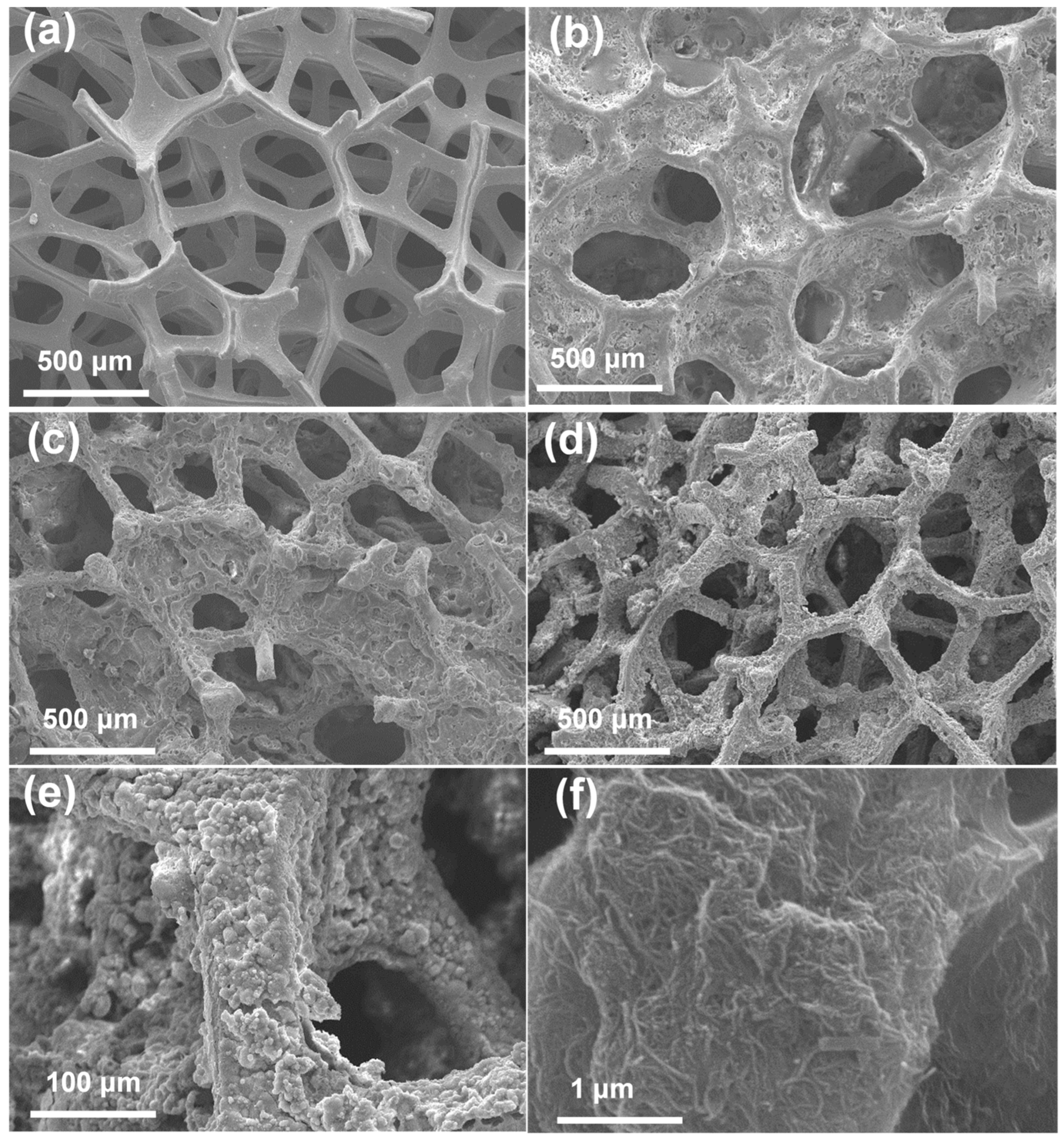
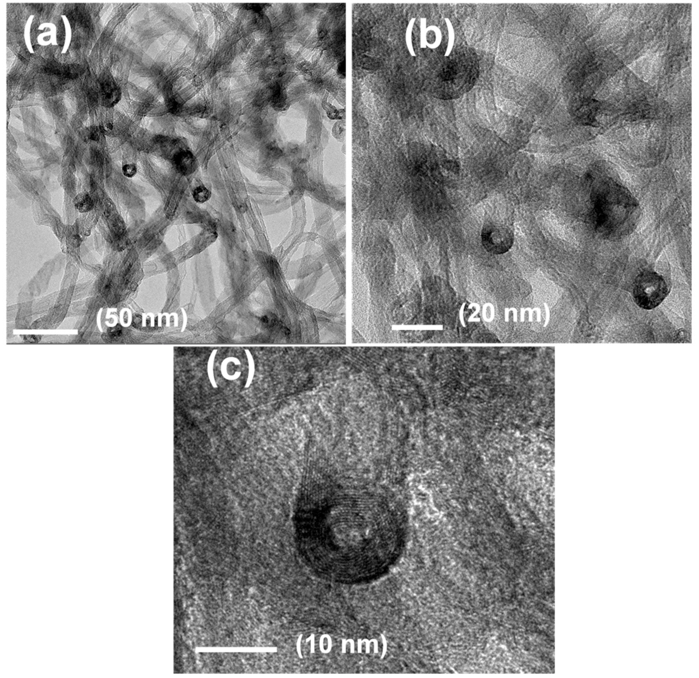
3.1. Morphological Features of CoP@P, N-CNTs/NF

The morphological and microstructural characteristics of the prepared electrodes—bare NF, CoP/NF, P, N-CNTs/NF, and CoP@P, N-CNTs/NF—were thoroughly analyzed using SEM. The images displayed in Figure 2 offer comprehensive insights into the surface topography, structural characteristics, and material distribution of each electrode, underscoring its appropriateness for electrocatalytic applications. Figure 2a presents an SEM image of the pure NF, which exhibits a highly porous, three-dimensional structure characterized by a smooth surface and a complex network of linked macropores. The holes, measuring between around 50 and 500 μm, create an open, sponge-like structure that optimizes surface area and enhances electrolyte transport and gas release during electrocatalytic reactions [56]. The uncoated, smooth surface of the NF struts establishes a reference for comparison with the modified electrodes and offers a mechanically resilient, conductive substrate for further material deposition [38,57]. Figure 2b presents an SEM image of the CoP/NF electrode, demonstrating the effective deposition of CoP onto the NF substrate. The CoP creates a heterogeneous coating, mostly consisting of nanoparticles and tiny aggregates, with particle sizes between 20 and 200 nm. The CoP coating preferentially accumulates in the concave regions, corners, and crevices of the NF structure, leading to a textured surface with increased roughness. This irregular distribution is due to the increased nucleation propensity in these recessed regions during the deposition phase. The CoP coating partially envelops the NF struts, exposing certain regions of the underlying NF, thereby facilitating a balance between catalytic activity and substrate conductivity [58]. Figure 2c presents an SEM image of the P, N-CNTs/NF electrode, demonstrating the uniform and conformal coverage of P, N-CNTs on the NF substrate. The CNTs, measuring between 10 and 50 nm in diameter, create a dense, entangled, and interconnected network that envelops the nanofiber surface, conforming closely to the foam’s porous architecture. The co-doping of P and N creates structural flaws and incorporates heteroatoms into the CNT lattice, hence improving their electrical conductivity and electrocatalytic characteristics. The conformal characteristics of the coating guarantee the preservation of the NF’s macroporous structure, facilitating effective electrolyte access and substantially enhancing the electrochemically active surface area. At Figure 2d, the SEM image of the CoP@P, N-CNTs/NF electrode displays a complex, hierarchical shape defined by the synergistic integration of P, N co-doped CNTs and CoP. The P, N-CNTs establish a fundamental layer, forming a web-like structure that uniformly envelops the NF surface. CoP nanoparticles, measuring between 50 and 300 nanometers, are uniformly and densely distributed over the CNT network on the CNT-coated NF. The high-magnification perspective emphasizes the close interaction between the CoP particles and the CNTs, which improves charge-transfer and catalytic synergy. This hybrid structure enhances the accessibility of electrocatalytic active sites, with the CNTs offering superior conductivity and the CoP delivering strong catalytic performance, culminating in an optimized electrode for electrocatalytic reactions. The high-magnification HR-SEM pictures in Figure 2e,f offer a comprehensive view of the CoP@P, N-CNTs/NF electrode, affirming the uniform and extensive distribution of P,N co-doped CNTs and CoP throughout the nickel foam structure. SEM images depict a continuous, interconnected CNTs network that envelops the nanofiber struts, preserving the foam’s open porosity while introducing a nanostructured surface layer. The CoP nanoparticles are evenly distributed throughout the CNT matrix, guaranteeing uniform coverage across the electrode’s macroscopic surface. The high-magnification SEM images highlight the structural integrity and scalability of the hybrid electrode, revealing no substantial aggregation or exposed areas. This uniform distribution underscores the effective synthesis and deposition process, facilitating a harmonious integration of the conductive P, N-CNTs and catalytically active CoP, thereby augmenting the electrode’s efficacy in applications such as OER and UOR. The SEM analysis illustrates the modified morphological development from the pure NF to the advanced CoP@P, N-CNTs/NF electrode, with each change enhancing the electrode’s electrocatalytic the ability via enhanced surface area, optimized active site density, and improved charge-transfer properties.
The nanostructural characteristics and compositional specifics of the CoP@P, N-CNTs/NF electrode were meticulously analyzed using HR-TEM at multiple magnifications, with the resultant pictures displayed in Figure 3. The TEM investigations yield high-resolution insights into the morphology, spatial configuration, and interfacial interactions of the P, N-CNTs, and CoP components integrated into the NF substrate, enhancing the knowledge of the electrode’s nano-scale architecture. Figure 3a provides a comprehensive perspective of the CoP@P, N-CNTs/NF electrode, illustrating the overall structural architecture of the hybrid material. The image depicts a network of intertwined, tubular structures representing the P, N co-doped carbon nanotubes, which are evenly scattered throughout the field of view. These carbon nanotubes, with sizes between 10 and 50 nanometers, create a porous, web-like structure that attaches to the underlying nickel foam substrate. Darker, particulate characteristics identified as CoP nanoparticles are interspersed inside this CNT network. The CoP particles, measuring between 20 and 100 nanometers, are uniformly distributed throughout the CNT matrix, demonstrating effective integration during the synthesis process. The low-magnification image suggests the presence of the NF surface, which functions as a conductive and mechanically stable support; nevertheless, its metallic characteristics lead to reduced contrast under TEM. This overview highlights the hierarchical structure of the electrode, integrating one-dimensional CNTs and zero-dimensional CoP nanoparticles within a three-dimensional NF framework.
Figure 3b presents a detailed TEM image of the P, N-CNTs and their interaction with the CoP nanoparticles. The P, N co-doped CNTs are distinctly identified as elongated, hollow tubes featuring smooth exterior surfaces and sporadic structural imperfections, including kinks or bends, resulting from the integration of phosphorus and nitrogen heteroatoms into the carbon lattice. These flaws augment the electrocatalytic capabilities of CNTs by creating active sites and enhancing electronic conductivity. The CoP nanoparticles are noted to be affixed to the surfaces of the CNTs, with certain particles largely integrated into the CNT matrix, indicating robust interfacial adhesion. The CoP particles display a crystalline structure, with lattice fringes observable in certain areas, signifying their polycrystalline characteristics. The intermediate-magnification image additionally displays a slender CoP shell layer enveloping portions of the CNTs, manifesting as a subtle, conformal coating around the nanotube walls. This shell, measuring around 2–5 nm in thickness, augments catalytic activity by elevating the density of CoP-related active sites while preserving the structural integrity of the CNTs. The close interaction between the CoP and CNTs enhances charge-transfer efficiency, which is essential for electrocatalytic performance. Figure 3c presents a high-magnification TEM picture that provides an intricate examination of the CoP@P, N-CNTs/NF electrode, emphasizing the nuanced structural and compositional characteristics of the hybrid material. At this resolution, the P, N co-doped CNTs exhibit a multi-walled structure, with concentric, graphene-like layers with an interlayer spacing of roughly 0.34 nm, aligning with standard CNT properties. The doping of phosphorus and nitrogen is indicated by minor abnormalities in the carbon lattice, which create localized electronic disturbances that improve catalytic activity. The CoP nanoparticles are depicted with enhanced clarity, exhibiting distinct lattice fringes that align with the crystalline planes of cobalt phosphide, as well as interplanar spacings that conform to established CoP crystallographic data (e.g., ~0.28 nm for the (011) plane). The high-magnification image verifies the existence of a distinct CoP shell layer surrounding sections of the CNTs, characterized by a homogeneous, amorphous coating with a thickness of 2–5 nm. This shell layer is firmly adhered to the CNT surface, guaranteeing strong mechanical and electrical contact [59].

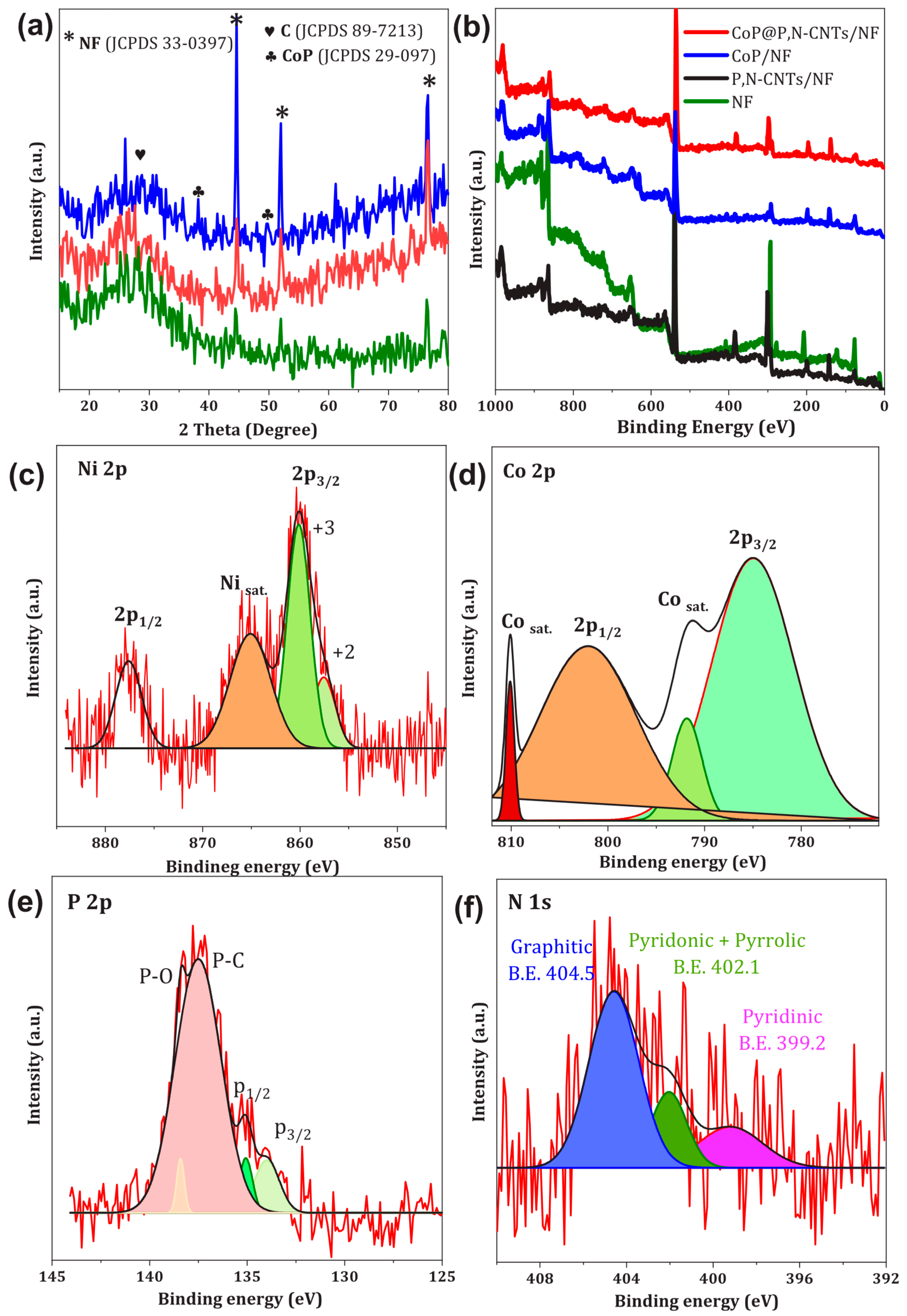
3.2. Crystalline and Chemical Composition Features of Electrodes

Figure 4a displays the X-ray diffraction (XRD) patterns of three electrode materials—NF, CoP/NF, and CoP@P, N-CNTs/NF—obtained throughout a 2θ range of 20° to 80° utilizing a Cu Kα radiation source (λ = 1.5406 Å). The XRD patterns offer comprehensive crystallographic data regarding the phase composition, crystallinity, and structural attributes of each electrode, clarifying the roles of the nickel foam substrate, cobalt phosphide, and P, N co-doped carbon nanotubes in the overall material structure. The XRD pattern of the uncoated NF substrate, indicated by the green line, has three distinct and sharp diffraction peaks at 2θ values of roughly 43.2°, 50.8°, and 74.7°. The peaks correspond to the (111), (200), and (220) crystallographic planes of face-centered cubic (FCC) metallic nickel, as indicated on JCPDS card No. 01-1260 [60,61]. The elevated intensity and narrow width of these peaks signify a highly crystalline structure of the nickel foam, aligning with its function as a durable, conductive, and mechanically stable substrate. The NF pattern reveals no new peaks, thus proving the lack of contaminants or secondary phases in the pristine foam, which acts as a baseline for the changed electrodes. The XRD pattern of the CoP/NF electrode, depicted by the blue line, illustrates the structural attributes of CoP applied to the NF substrate. Alongside the three principal peaks from the NF substrate at 43.2°, 50.8°, and 74.7°, which are noticeable due to the underlying NF, the pattern displays two low-intensity diffraction peaks at roughly 38.1° and 48.3°. The peaks correspond to the (200) and (211) planes of orthorhombic cobalt phosphide (CoP), as recorded in JCPDS card No. 29-0497 [59].
The diminished intensity and widened characteristics of these CoP peaks indicate a mostly amorphous or nanocrystalline structure, commonly observed in CoP produced under specific conditions, such as electrodeposition or low-temperature phosphidation. The amorphous structure increases the accessibility of catalytic active sites owing to the presence of disordered surface atoms, which is advantageous for electrocatalytic OER and UOR. The XRD pattern of the CoP@P, N-CNTs/NF electrode, illustrated by the red line, indicates the intricate composition of this hybrid material, which combines P, N co-doped CNTs with CoP on the NF substrate. The pattern preserves the three distinctive peaks of the NF substrate at 43.2°, 50.8°, and 74.7°, signifying that the underlying NF maintains its structural integrity and predominates the diffraction signal owing to its superior crystallinity and thickness. A wide, low-intensity peak centered at approximately 27.3° is detected, corresponding to the (002) plane of hexagonal graphitic carbon, as shown by JCPDS card No. 89-7213 [62,63]. This peak is indicative of the graphitic structure of carbon nanotubes, affirming the existence of P, N co-doped CNTs in the electrode. The widening of this peak indicates a somewhat disordered graphitic structure, possibly caused by the introduction of phosphorus and nitrogen heteroatoms, which create lattice defects and strain inside the CNT framework. These flaws augment the electronic and catalytic characteristics of the CNTs by generating supplementary active sites.
X-ray photoelectron spectroscopy (XPS) was employed to analyze the surface elemental composition and valence states of the deposited catalysts. The XPS survey spectrum (Figure 4b) confirmed the presence of Ni, Co, P, N, and C elements in the samples. High-resolution XPS analysis of Ni 2p (Figure 4c) revealed characteristic peaks for Ni 2p1/2 and Ni 2p3/2 at binding energies of 856 eV and 875 eV, respectively, for the NF substrate. Upon incorporation of Co and heteroatoms (P, N), these peaks exhibited a shift toward higher binding energies, indicating successful deposition on the NF substrate. The Co 2p spectrum of CoP@P, N-CNTs/NF (Figure 4d) displayed typical peaks for Co 2p1/2 and Co 2p3/2 at approximately 795 eV and 781 eV, respectively, corresponding to oxidized cobalt species. Analysis of the P 2p spectrum (Figure 4e) showed peaks at 129.1 eV and 137.4 eV, attributable to P 2p3/2 and P 2p1/2 of phosphorus species in CoP, respectively. Deconvolution of the N 1s spectrum revealed three distinct peaks corresponding to pyridinic (398.6 eV), pyrrolic (399.8 eV), and graphitic (401.2 eV) nitrogen configuration (Figure 4f).

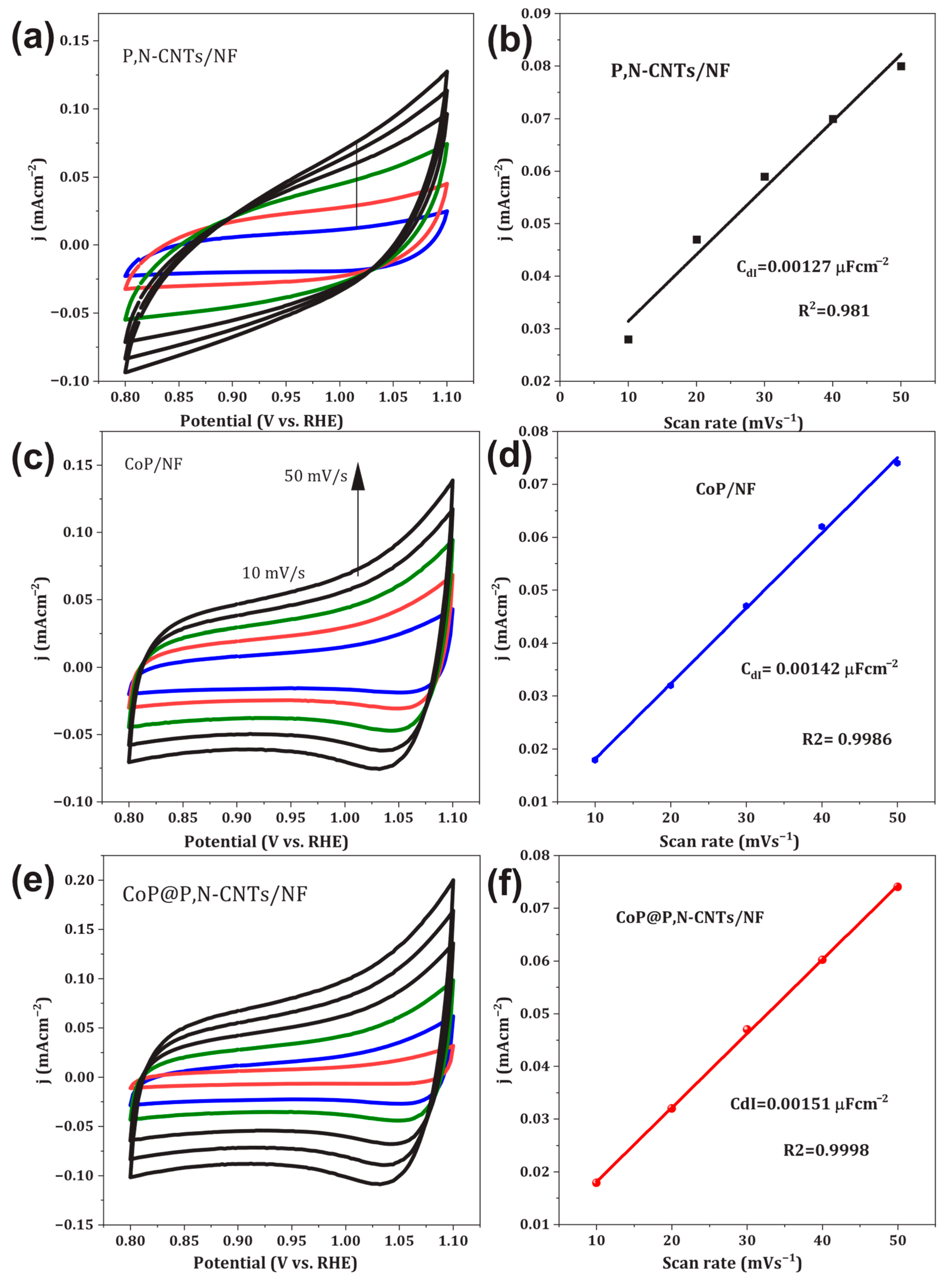
3.3. Electrochemical Properties of Catalysts

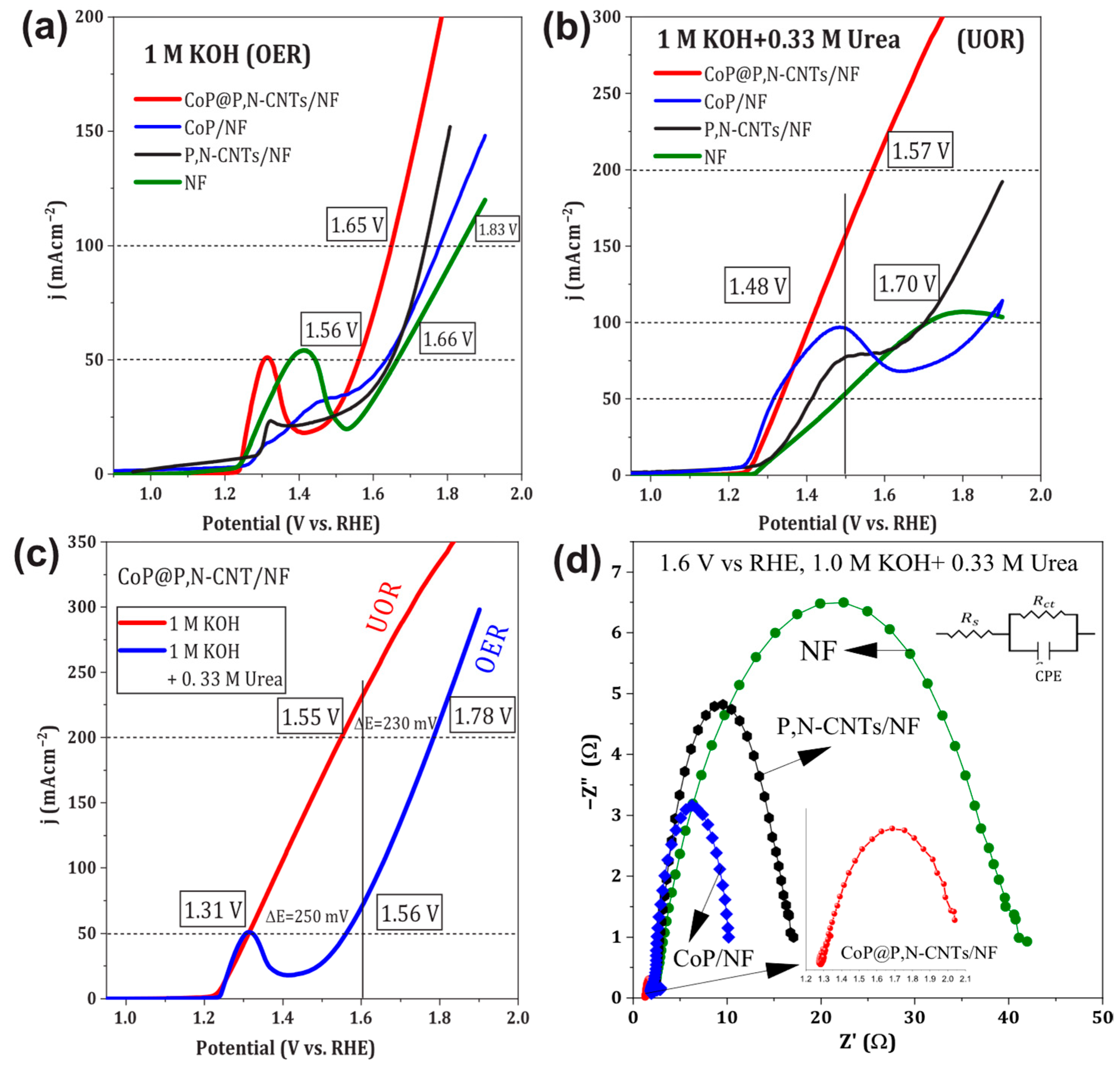
3.3.1. OER and UOR Characteristics

Figure 5a illustrates the current density versus voltage (j–v) plots for the oxygen evolution reaction (OER) in an alkaline medium (1.0 M KOH, pH 13.6) across various electrode configurations: optimally designed cobalt phosphide on nickel foam (CoP/NF), phosphorus and nitrogen co-doped carbon nanotubes on nickel foam (P, N-CNTs/NF), cobalt phosphide integrated with phosphorus and nitrogen co-doped carbon nanotubes on nickel foam (CoP@P, N-CNTs/NF), and pure nickel foam (NF) electrode. These figures demonstrate the electrocatalytic performance of each electrode under experimental settings, emphasizing variations in their OER efficiencies.
Figure 5b illustrates the j–v plots for the urea oxidation process (UOR) in an electrolyte of 1.0 M KOH + 0.33 M urea, contrasting the identical array of electrodes: CoP/NF, P, N-CNTs/NF, CoP@P, N-CNTs/NF, and pure NF. The CoP@P, N-CNTs/NF electrode exhibits exceptional performance for the OER, attaining a current density of 160 mA cm−2 at an applied voltage of 1.5 V vs. RHE. This signifies a greater-than-three-fold-increase in current density relative to the pure NF electrode at the identical potential. The onset potential for OER on the CoP@P, N-CNTs/NF electrode is markedly diminished to 430 mV, signifying enhanced catalytic efficiency and lowered energy demands for reaction initiation.
Figure 5c presents additional analysis, featuring LSV graphs for the CoP@P, N-CNTs/NF electrode in 1.0 M KOH, conducted with and without 0.33 M urea, at a scan rate of 20 mV s−1. This electrode attains a current density of 50 mA cm−2 for OER at an applied voltage of 1.55 V vs. RHE, resulting in an overpotential of 320 mV. Conversely, the CoP/NF, P, N-CNTs/NF, and pure NF electrodes necessitate elevated potentials of 1.63 V, 1.65 V, and 1.66 V vs. RHE, respectively, to obtain the equivalent current density, resulting in overpotentials of 400 mV, 420 mV, and 430 mV. An oxidation peak at about 1.31 V vs. RHE is ascribed to the electrochemical transformation of Ni2+ to Ni3+, a typical characteristic of nickel-based electrodes. Electrochemical impedance spectroscopy (EIS) was utilized to investigate the electrical conductivity of the electrocatalysts. Figure 5d displays the equivalent circuit used to interpret the EIS data for the urea oxidation reaction. The circuit consists of the solution resistance (Rs), charge-transfer resistance (Rct), and a constant phase element (CPE) to model the non-ideal capacitive behavior at the electrode/electrolyte interface [64,65,66]. Figure 5d demonstrates that the CoP@P, N-CNTs/NF electrode displays a remarkably low charge-transfer resistance (Rct) of 2.21 Ω at 1.6 V in 1.0 M KOH + 0.33 M urea, considerably lower than that of the other electrodes evaluated. The low Rct value signifies improved electrical conductivity and accelerated charge-transfer kinetics, which enhance the electrode’s electrocatalytic activity. The EIS Nyquist plots (Figure 5d) show a compressed semicircle for all tested electrodes. In an ideal RC circuit, a perfect semicircle is expected; however, the observed compression in our system is indicative of non-ideal capacitive behavior, often arising from surface roughness, porosity, and heterogeneity of the electrode. This behavior is commonly represented by incorporating a constant phase element (CPE) into the equivalent circuit model. The smaller semicircle diameter for the CoP@P, N-CNTs/NF electrode corresponds to a lower charge-transfer resistance (Rct), suggesting more efficient electron transfer at the electrode/electrolyte interface. This reduced Rct aligns with the enhanced electrocatalytic activity observed in our other measurements and further supports the beneficial effect of our one-step synthesized, hierarchical electrode architecture. These findings could be attributed to the combination of co-doped CNTs and NF substrates that create a hierarchical porous structure with both macro- and nano-scale features, optimizing mass transport and active site accessibility.
It is important to note that during prolonged urea oxidation, organic molecules and reaction intermediates may specifically adsorb onto the Ag/AgCl reference electrode, potentially influencing the measured reference potential and the accuracy of EIS measurements [67,68]. Although every effort was made to minimize contamination (e.g., by positioning the reference electrode away from the main reaction zone and by frequent cleaning), such adsorption effects cannot be entirely ruled out. This is a common challenge in EIS studies of organic-rich electrolytes and should be considered when interpreting the resistance values and overall impedance spectra.
Table 1 delineates the requisite applied potentials to attain current densities of 50, 100, and 200 mA cm−2 for the OER and UOR in 1.0 M KOH + 0.33 M urea for the NF, CoP/NF, P, N-CNTs/NF, and CoP@P, N-CNTs/NF electrodes. The CoP@P, N-CNTs/NF electrode consistently provides superior current densities at reduced potentials relative to the other electrodes. The improved performance is due to the synergistic effects of co-doping P and N in the CNTs structure, along with the catalytic characteristics of CoP on the NF substrate. These interactions enhance the electrical configuration and accessibility of active sites, resulting in increased electrocatalytic performance.
Cyclic voltammetry (CV) measurements were performed in a non-faradaic potential window of 0.8–1.10 V vs. RHE at varying scan rates of 10, 20, 30, 40, and 50 mV s−1 to determine the double-layer capacitance (Cdl) of the electrodes (Figure 6a,c,e). The capacitive current densities at each scan rate were plotted, and the slope of the resulting linear fit was used to calculate Cdl for each sample, as shown in Figure 6b,d,f. Among the tested electrodes, CoP@P, N-CNTs/NF exhibited the highest Cdl value of 0.0017 μF/cm2, followed by CoP/NF at 0.00142 μF/cm2, and P, N-CNTs/NF at 0.00127 μF/cm2.
The electrochemically active surface area (ECSA) was subsequently estimated using the measured Cdl values and a specific capacitance (Cs) value typical for a flat surface in alkaline media. CoP@P, N-CNTs/NF displayed a significantly larger ECSA of 93 cm2, compared to 35.5 cm2 for CoP/NF and 31.75 cm2 for P, N-CNTs/NF, as summarized in Figure 6. These results indicate that the CoP@P, N-CNTs/NF electrode possesses a substantially higher number of electrochemically active sites, which is expected to contribute to its superior catalytic activity toward urea oxidation.
The resulting current density versus scan rate plots exhibited excellent linearity (R2 = 0.9998) for the CoP@P, N-CNTs/NF electrode, confirming the reliability of the Cdl extraction.

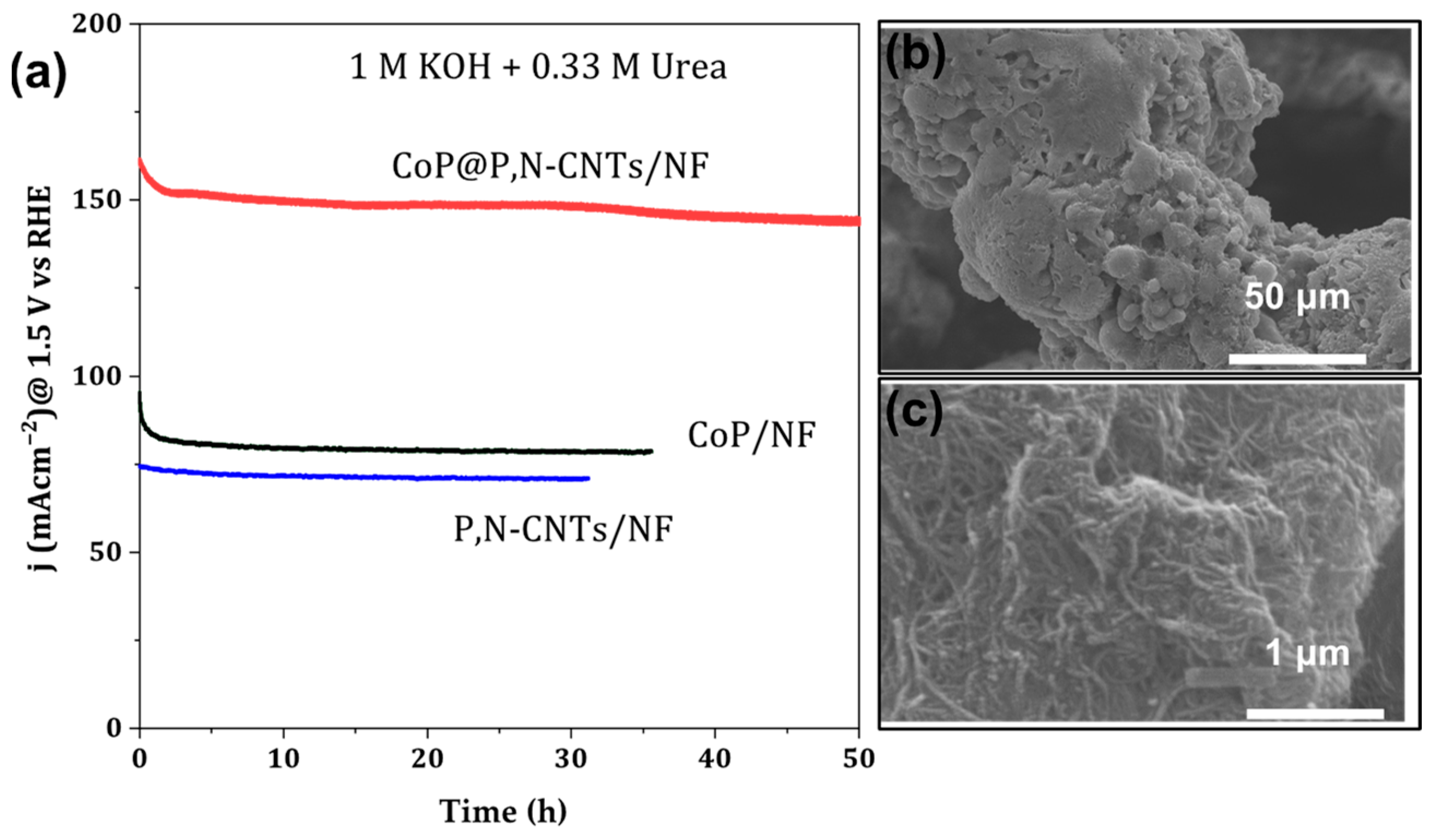
3.3.2. Long-Term Stability

The long-term stability of the P, N-CNTs/NF, CoP/NF, and CoP@P, N-CNTs/NF electrodes were evaluated using chronoamperometric measurements at 1.5 V vs. RHE in a conventional three-electrode system. For these tests, 250 mL of 0.1 M KOH containing 0.33 M urea served as the electrolyte. The experiments were conducted in batch mode, with no replacement or replenishment of the solution throughout the entire measurement period, thus simulating practical operational conditions. Figure 7a presents the chronoamperometric stability curves for all electrodes. Among the tested samples, the CoP@P, N-CNTs/NF electrode demonstrated outstanding stability, exhibiting negligible loss in current density over approximately 50 h of continuous operation. Post-stability HR-TEM analysis (Figure 7b,c) further confirmed that the microstructure of CoP@P, N-CNTs/NF remained unchanged after prolonged electrolysis, indicating remarkable structural robustness. This high degree of stability was consistently observed across multiple fabricated samples, underscoring the reproducibility provided by our single-step synthesis method.
The exceptional durability and performance of the CoP@P, N-CNTs/NF electrode can be attributed to the synergistic effects between CoP nanoparticles and the P, N co-doped CNTs, as well as the presence of structural defects that promote enhanced electrocatalytic activity for urea oxidation reaction (UOR). Furthermore, the electrode’s high current density, efficient electron transport, and excellent mechanical integrity highlight its strong potential for practical applications in energy-efficient hydrogen generation and wastewater treatment.

4. Conclusions

In summary, we have developed a simple and effective one-step thermal annealing process under nitrogen atmosphere to fabricate nickel foam (NF) electrodes uniformly coated with CoP@P, N-CNTs. This method enables the direct integration of phosphorus and nitrogen co-doped carbon nanotubes (P, N-CNTs) and a conformal CoP shell onto NF, resulting in a robust and highly active electrode architecture. The CoP@P, N-CNTs/NF electrode demonstrates outstanding electrocatalytic performance for urea oxidation reaction (UOR), achieving current densities of 158.5 mA cm−2 at 1.5 V and 232.95 mA cm−2 at 1.6 V versus RHE. Notably, the electrode maintains excellent long-term operational stability, with negligible performance loss over 50 h of continuous operation. The synergistic effects of P, N co-doping in CNTs and the presence of CoP nanoparticles contribute to enhanced catalytic activity and durability, representing a significant advancement in NF-based electrocatalysts. This work highlights the importance of rational doping strategies and streamlined fabrication techniques, offering a promising and cost-effective route for the development of efficient UOR electrodes and advancing the field of sustainable hydrogen generation.

Author Contributions

H.M.Y.: data curation, formal analysis, funding acquisition, project administration. M.N.S.: conceptualization, data curation, formal analysis, investigation, writing—review and editing, supervision. S.A.A.: data curation, review and editing, formal analysis, investigation. A.M.A.: review and editing, formal analysis, data curation. All authors have read and agreed to the published version of the manuscript.

Funding

The authors extend their appreciation to Prince Sattam bin Abdulaziz University for funding this research work through the project number (PSAU/2024/01/22467).

Data Availability Statement

All data generated or analyzed during this study are included in this published article.

Conflicts of Interest

The authors declare no conflicts of interest.

References

  1. Strielkowski, W.; Civín, L.; Tarkhanova, E.; Tvaronavičienė, M.; Petrenko, Y. Renewable Energy in the Sustainable Development of Electrical Power Sector: A Review. Energies 2021, 14, 8240. [Google Scholar] [CrossRef]
  2. Qazi, A.; Hussain, F.; Rahim, N.A.B.D.; Hardaker, G.; Alghazzawi, D.; Shaban, K.; Haruna, K. Towards Sustainable Energy: A Systematic Review of Renewable Energy Sources, Technologies, and Public Opinions. IEEE Access 2019, 7, 63837–63851. [Google Scholar] [CrossRef]
  3. Agyekum, E.B.; Nutakor, C.; Agwa, A.M.; Kamel, S.; Kame, S. A Critical Review of Renewable Hydrogen Production Methods: Factors Affecting Their Scale-Up and Its Role in Future Energy Generation. Membranes 2022, 12, 173. [Google Scholar] [CrossRef] [PubMed]
  4. Wang, M.; Wang, G.; Sun, Z.; Zhang, Y.; Xu, D. Review of Renewable Energy-Based Hydrogen Production Processes for Sustainable Energy Innovation. Glob. Energy Interconnect. 2020, 2, 436–443. [Google Scholar] [CrossRef]
  5. Sun, H.; Xu, X.; Kim, H.; Jung, W.C.; Zhou, W.; Shao, Z. Electrochemical Water Splitting: Bridging the Gaps Between Fundamental Research and Industrial Applications. Energy Environ. Mater. 2023, 6, e12441. [Google Scholar] [CrossRef]
  6. Kumar, S.; Rajan, A.; Rugma, T.P.; Bernaurdshaw, N. A Review on Particulate Photocatalytic Hydrogen Production System: Progress Made in Achieving High Energy Conversion Efficiency and Key Challenges Ahead. Renew. Sustain. Energy Rev. 2021, 152, 111694. [Google Scholar]
  7. Zhu, B.; Liang, Z.; Zou, R. Designing Advanced Catalysts for Energy Conversion Based on Urea Oxidation Reaction, REVIEW. Small 2020, 16, 1906133. [Google Scholar] [CrossRef]
  8. Qiu, Z. Transition Metal-Based Electrocatalysts for Alkaline Water Splitting and CO2 Reduction-Dissertation; Ångström Laboratory: Uppsala, Sweden, 2019. [Google Scholar]
  9. Yang, X.; Sun, X.; Qi, J.; Zhang, J.; Zheng, X.; Zhang, X.; Lei, F.; Sun, X.; Tang, B.; Xie, J. Two-Dimensional Confined Topotactic Transformation to Produce Co-Pi/Co3O4 Hybrid Porous Nanosheets for Promoted Water Oxidation. J. Colloid Interface Sci. 2025, 677, 406–416. [Google Scholar] [CrossRef]
  10. Chen, J.; Wang, K.; Liu, Z.; Sun, X.; Zhang, X.; Lei, F.; Wan, X.; Xie, J.; Tang, B. Sulfurization-Induced Lattice Disordering in High-Entropy Catalyst for Promoted Bifunctional Electro-Oxidation Behavior. Chem. Eng. J. 2024, 489, 151234. [Google Scholar] [CrossRef]
  11. Noor, T.; Yaqoob, L.; Iqbal, N. Recent Advances in Electrocatalysis of Oxygen Evolution Reaction Using Noble-Metal, Transition-Metal, and Carbon-Based Materials. ChemElectroChem 2021, 8, 447–483. [Google Scholar] [CrossRef]
  12. Chang, H.; Liang, Z.; Wang, L.; Wang, C. Research Progress in Improving the Oxygen Evolution Reaction by Adjusting the 3d Electronic Structure of Transition Metal Catalysts. Nanoscale 2022, 14, 5639–5656. [Google Scholar] [CrossRef]
  13. Omar ben Gubaer, S.; Shaddad, M.N.; Arunachalam, P.; Amer, M.S.; Aladeemy, S.A.; Al-Mayouf, A.M. Enhanced Electrocatalytic Oxygen Redox Reactions of Iron Oxide Nanorod Films by Combining Oxygen Vacancy Formation and Cobalt Doping. RSC Adv. 2023, 13, 33242–33254. [Google Scholar] [CrossRef]
  14. Shaddad, M.N.; Alharthi, A.I.; Aladeemy, S.A.; Arunachalam, P. Engineering Oxygen Vacancy on Nickel-Doped Iron Oxide Nanorods as Efficient Bifunctional Electrocatalysts for Oxygen Evolution and Urea Oxidation Reaction. J. Taiwan Inst. Chem. Eng. 2024, 105928, in press. [Google Scholar] [CrossRef]
  15. Aladeemy, S.A.; Arunachalam, P.; Al-Mayouf, A.M.; Sudha, P.N.; Rekha, A.; Vidhya, A.; Hemapriya, J.; Latha, S.; Prasad, P.S.; Pavithra, S.; et al. Engineered CoS/Ni3S2 Heterointerface Catalysts Grown Directly on Carbon Paper as an Efficient Electrocatalyst for Urea Oxidation. Catalysts 2024, 14, 570. [Google Scholar] [CrossRef]
  16. Aladeemy, S.A.; Arunachalam, P.; Amer, M.S.; Al-Mayouf, A.M. Electrochemically Embedded Heterostructured Ni/NiS Anchored onto Carbon Paper as Bifunctional Electrocatalysts for Urea Oxidation and Hydrogen Evolution Reaction. RSC Adv. 2025, 15, 14–25. [Google Scholar] [CrossRef]
  17. Al-Sulmi, W.A.; Ghanem, M.A.; Aladeemy, S.A.; Al-Mayouf, A.M.; Alotaibi, N.H. Chemical Deposition from a Liquid Crystal Template: A Highly Active Mesoporous Nickel Phosphate Electrocatalyst for Hydrogen Green Production via Urea. Arab. J. Chem. 2023, 16, 105266. [Google Scholar] [CrossRef]
  18. Hu, X.; Zhu, J.; Li, J.; Wu, Q. Urea Electrooxidation: Current Development and Understanding of Ni-Based Catalysts. ChemElectroChem 2020, 7, 3211–3228. [Google Scholar] [CrossRef]
  19. Li, Q.; Wang, Y.; Pan, T.; Zhu, Y.; Pang, H. Ni-Based Electrocatalysts for Urea Oxidation Reaction: Mechanism, Catalyst Design Strategies and Future Perspectives. Sci. China Mater. 2025, 68, 317–340. [Google Scholar] [CrossRef]
  20. Wang, G.; Chen, J.; Li, Y.; Jia, J.; Cai, P.; Wen, Z. Energy-Efficient Electrolytic Hydrogen Production Assisted by Coupling Urea Oxidation with a PH-Gradient Concentration Cell. Chem. Commun. 2018, 54, 2603–2606. [Google Scholar] [CrossRef]
  21. Aladeemy, S.A.; Al-Mayouf, A.M.; Shaddad, M.N.; Amer, M.S.; Almutairi, N.K.; Ghanem, M.A.; Alotaibi, N.H.; Arunachalam, P. Electrooxidation of Urea in Alkaline Solution Using Nickel Hydroxide Activated Carbon Paper Electrodeposited from DMSO Solution. Catalysts 2021, 11, 102. [Google Scholar] [CrossRef]
  22. Hao, M.; Chen, J.; Chen, J.; Wang, K.; Wang, J.; Lei, F.; Hao, P.; Sun, X.; Xie, J.; Tang, B. Lattice-Disordered High-Entropy Metal Hydroxide Nanosheets as Efficient Precatalysts for Bifunctional Electro-Oxidation. J. Colloid Interface Sci. 2023, 642, 41–52. [Google Scholar] [CrossRef]
  23. Sun, W.; Li, J.; Gao, W.; Kang, L.; Lei, F.; Xie, J. Recent Advances in the Pre-Oxidation Process in Electrocatalytic Urea Oxidation Reactions. Chem. Commun. 2022, 58, 2430–2442. [Google Scholar] [CrossRef] [PubMed]
  24. Yang, X.; Kang, L.; Wei, Z.; Lou, S.; Lei, F.; Hao, P.; Xie, J.; Tang, B. A Self-Sacrificial Templated Route to Fabricate CuFe Prussian Blue Analogue/Cu(OH)2 Nanoarray as an Efficient Pre-Catalyst for Ultrastable Bifunctional Electro-Oxidation. Chem. Eng. J. 2021, 422, 130139. [Google Scholar] [CrossRef]
  25. Wei, Z.; Sun, W.; Liu, S.; Qi, J.; Kang, L.; Li, J.; Lou, S.; Xie, J.; Tang, B.; Xie, Y. Lanthanum-Doped α-Ni(OH)2 1D-2D-3D Hierarchical Nanostructures for Robust Bifunctional Electro-Oxidation. Particuology 2021, 57, 104–111. [Google Scholar] [CrossRef]
  26. Xie, J.; Gao, L.; Cao, S.; Liu, W.; Lei, F.; Hao, P.; Xia, X.; Tang, B. Copper-Incorporated Hierarchical Wire-on-Sheet α-Ni(OH)2 Nanoarrays as Robust Trifunctional Catalysts for Synergistic Hydrogen Generation and Urea Oxidation. J. Mater. Chem. A 2019, 7, 13577–13584. [Google Scholar] [CrossRef]
  27. Xie, J.; Qu, H.; Lei, F.; Peng, X.; Liu, W.; Gao, L.; Hao, P.; Cui, G.; Tang, B. Partially Amorphous Nickel-Iron Layered Double Hydroxide Nanosheet Arrays for Robust Bifunctional Electrocatalysis. J. Mater. Chem. A 2018, 6, 16121–16129. [Google Scholar] [CrossRef]
  28. Xie, J.; Liu, W.; Lei, F.; Zhang, X.; Qu, H.; Gao, L.; Hao, P.; Tang, B.; Xie, Y. Iron-Incorporated α-Ni(OH)2 Hierarchical Nanosheet Arrays for Electrocatalytic Urea Oxidation. Chem.–A Eur. J. 2018, 24, 18408–18412. [Google Scholar] [CrossRef]
  29. Hopsort, G.; Carmo, D.P.D.; Latapie, L.; Loubière, K.; Serrano, K.G.; Tzedakis, T. Progress toward a Better Understanding of the Urea Oxidation by Electromediation of Ni(III)/Ni(II) System in Alkaline Media. Electrochim. Acta 2023, 442, 141898. [Google Scholar] [CrossRef]
  30. Boggs, B.K.; King, R.L.; Botte, G.G. Urea Electrolysis: Direct Hydrogen Production from Urine. Chem. Commun. 2009, 2009, 4859–4861. [Google Scholar] [CrossRef]
  31. Ma, Y.; Ma, C.; Wang, Y.; Wang, K. Advanced Nickel-Based Catalysts for Urea Oxidation Reaction: Challenges and Developments. Catalysts 2022, 12, 337. [Google Scholar] [CrossRef]
  32. Asnavandi, M. Nanostructured Metallic Catalysts for Electrochemical Energy Conversion-Dissertation. Ph.D. Thesis, University of New South Wales, Sydney, Australia, 2017. [Google Scholar]
  33. Singh, R.K.; Schechter, A. Electrochemical Investigation of Urea Oxidation Reaction on β Ni(OH)2 and Ni/Ni(OH)2. Electrochim. Acta 2018, 278, 405–411. [Google Scholar] [CrossRef]
  34. Wei, S.; Wang, X.; Wang, J.; Sun, X.; Cui, L.; Yang, W.; Zheng, Y.; Liu, J. CoS2 Nanoneedle Array on Ti Mesh: A Stable and Efficient Bifunctional Electrocatalyst for Urea-Assisted Electrolytic Hydrogen Production. Electrochim. Acta 2017, 246, 776–782. [Google Scholar] [CrossRef]
  35. Yan, Y.; Xia, B.Y.; Zhao, B.; Wang, X. A Review on Noble-Metal-Free Bifunctional Heterogeneous Catalysts for Overall Electrochemical Water Splitting. J. Mater. Chem. A 2016, 4, 17587–17603. [Google Scholar] [CrossRef]
  36. Cheng, Y.; Liao, F.; Dong, H.; Wei, H.; Geng, H.; Shao, M. Engineering CoN/Ni(OH)2 Heterostructures with Improved Intrinsic Interfacial Charge Transfer toward Simultaneous Hydrogen Generation and Urea-Rich Wastewater Purification. J. Power Sources 2020, 480, 229151. [Google Scholar] [CrossRef]
  37. Vidhya, M.S.; Ravi, G.; Yuvakkumar, R.; Velauthapillai, D.; Thambidurai, M.; Dang, C.; Saravanakumar, B. Nickel-Cobalt Hydroxide: A Positive Electrode for Supercapacitor Applications. RSC Adv. 2020, 10, 19410–19418. [Google Scholar] [CrossRef]
  38. Aladeemy, S.A.; AlRijraji, T.R.; Amer, M.S.; Arunachalam, P.; Al-Mayouf, A.M. Electrooxidation of Ethylene Glycol Coupled with Hydrogen Production on Porous NiO/Ni@NF Nanosheet Electrocatalysts. Catal. Sci. Technol. 2025, 15, 2571–2583. [Google Scholar] [CrossRef]
  39. Xu, X.; Wang, T.; Su, L.; Zhang, Y.; Dong, L.; Miao, X. In Situ Synthesis of Superhydrophilic Amorphous NiFe Prussian Blue Analogues for the Oxygen Evolution Reaction at a High Current Density. ACS Sustain. Chem. Eng. 2021, 9, 5693–5704. [Google Scholar] [CrossRef]
  40. Guo, F.; Cao, D.; Du, M.; Ye, K.; Wang, G.; Zhang, W.; Gao, Y.; Cheng, K. Enhancement of Direct Urea-Hydrogen Peroxide Fuel Cell Performance by Three-Dimensional Porous Nickel-Cobalt Anode. J. Power Sources 2016, 307, 697–704. [Google Scholar] [CrossRef]
  41. Peng, L.; Shen, J.; Zheng, X.; Xiang, R.; Deng, M.; Mao, Z.; Feng, Z.; Zhang, L.; Li, L.; Wei, Z. Rationally Design of Monometallic NiO-Ni3S2/NF Heteronanosheets as Bifunctional Electrocatalysts for Overall Water Splitting. J. Catal. 2019, 369, 345–351. [Google Scholar] [CrossRef]
  42. Yu, H.; Quan, T.; Mei, S.; Kochovski, Z.; Huang, W.; Meng, H.; Lu, Y. Prompt Electrodeposition of Ni Nanodots on Ni Foam to Construct a High-Performance Water-Splitting Electrode: Efficient, Scalable, and Recyclable. Nano-Micro Lett. 2019, 11, 41. [Google Scholar] [CrossRef]
  43. Babar, P.; Patil, K.; Lee, D.M.; Karade, V.; Gour, K.; Pawar, S.; Kim, J.H. Cost-Effective and Efficient Water and Urea Oxidation Catalysis Using Nickel-Iron Oxyhydroxide Nanosheets Synthesized by an Ultrafast Method. J. Colloid Interface Sci. 2021, 584, 760–769. [Google Scholar] [CrossRef] [PubMed]
  44. Yan, X.; Hu, Q.T.; Wang, G.; Zhang, W.D.; Liu, J.; Li, T.; Gu, Z.G. NiCo Layered Double Hydroxide/Hydroxide Nanosheet Heterostructures for Highly Efficient Electro-Oxidation of Urea. Int. J. Hydrogen Energy 2020, 45, 19206–19213. [Google Scholar] [CrossRef]
  45. Wang, Y.-T.; He, X.-F.; Chen, X.-M.; Zhang, Y.; Li, F.-T.; Zhou, Y.; Meng, C. Laser Synthesis of Cobalt-Doped Ni3S4-NiS/Ni as High-Efficiency Supercapacitor Electrode and Urea Oxidation Electrocatalyst. Appl. Surf. Sci. 2022, 596, 153600. [Google Scholar] [CrossRef]
  46. Justyna, Ł.; Lieder, M. Nickel-Based Catalysts for Electrolytic Decomposition of Ammonia towards Hydrogen Production. Adv. Colloid Interface Sci. 2023, 319, 102963. [Google Scholar]
  47. Patil, S.J.; Chodankar, N.R.; Hwang, S.K.; Rama Raju, G.S.; Huh, Y.S.; Han, Y.K. Fluorine Engineered Self-Supported Ultrathin 2D Nickel Hydroxide Nanosheets as Highly Robust and Stable Bifunctional Electrocatalysts for Oxygen Evolution and Urea Oxidation Reactions. Small 2022, 18, 2103326. [Google Scholar] [CrossRef] [PubMed]
  48. Zhou, W.; Zhao, J.; Guan, J.; Wu, M.; Li, G.R. Ni3S2 in Situ Grown on Ni Foam Coupled with Nitrogen-Doped Carbon Nanotubes as an Efficient Electrocatalyst for the Hydrogen Evolution Reaction in Alkaline Solution. ACS Omega 2019, 4, 20244–20251. [Google Scholar] [CrossRef] [PubMed]
  49. Zheng, X.; Chen, S.; Li, J.; Wu, H.; Zhang, C.; Zhang, D.; Chen, X.; Gao, Y.; He, F.; Hui, L.; et al. Two-Dimensional Carbon Graphdiyne: Advances in Fundamental and Application Research. ACS Nano 2023, 17, 14309–14346. [Google Scholar] [CrossRef]
  50. Al-Enizi, A.M.; Ghanem, M.A.; El-Zatahry, A.A.; Al-Deyab, S.S. Nickel Oxide/Nitrogen Doped Carbon Nanofibers Catalyst for Methanol Oxidation in Alkaline Media. Electrochim. Acta 2014, 137, 774–780. [Google Scholar] [CrossRef]
  51. Karuppiah, C.; Venkatesh, K.; Arunachalam, P.; Ramaraj, S.K.; Al-Mayouf, A.M.; Yang, C.C. Optimization of S-Dopant on N, S Co-Doped Graphene/CNT-Fe3C Nanocomposite Electrode for Non-Enzymatic H2O2 Sensor. Mater. Lett. 2021, 285, 129001. [Google Scholar] [CrossRef]
  52. Zhang, H.; Wang, T.; Sumboja, A.; Zang, W.; Xie, J.; Gao, D.; Pennycook, S.J.; Liu, Z.; Guan, C.; Wang, J. Integrated Hierarchical Carbon Flake Arrays with Hollow P-Doped CoSe2 Nanoclusters as an Advanced Bifunctional Catalyst for Zn–Air Batteries. Adv. Funct. Mater. 2018, 28, 1–9. [Google Scholar] [CrossRef]
  53. Abdelkareem, M.A.; Al Haj, Y.; Alajami, M.; Alawadhi, H.; Barakat, N.A.M. Ni-Cd Carbon Nanofibers as an Effective Catalyst for Urea Fuel Cell. J. Environ. Chem. Eng. 2018, 6, 332–337. [Google Scholar] [CrossRef]
  54. Yan, L.; Sun, Y.; Hu, E.; Ning, J.; Zhong, Y.; Zhang, Z.; Hu, Y. Facile In-Situ Growth of Ni2P/Fe2P Nanohybrids on Ni Foam for Highly Efficient Urea Electrolysis. J. Colloid Interface Sci. 2019, 541, 279–286. [Google Scholar] [CrossRef]
  55. Qian, G.; Chen, J.; Luo, L.; Zhang, H.; Chen, W.; Gao, Z.; Yin, S.; Tsiakaras, P. Novel Bifunctional V2O3Nanosheets Coupled with N-Doped-Carbon Encapsulated Ni Heterostructure for Enhanced Electrocatalytic Oxidation of Urea-Rich Wastewater. ACS Appl. Mater. Interfaces 2020, 12, 38061–38069. [Google Scholar] [CrossRef] [PubMed]
  56. Kareem, A.; Jose, E.; Thenmozhi, K.; Senthilkumar, S. In Situ Growth of Trimetallic FeCoNi Selenide Nanosheets on Nickel Foam for Electrocatalytic Water Splitting. ACS Appl. Nano Mater. 2025, 8, 8424–8432. [Google Scholar] [CrossRef]
  57. Leuaa, P.; Farzin, Y.A.; Iqbal, S.; Chatzichristodoulou, C. Cobalt Oxide (CoOx) Coated Ni Foam Anodes for High Temperature (150 °C) and Pressure (45 Bar) Alkaline Electrolysis. J. Power Sources 2025, 625, 235625. [Google Scholar] [CrossRef]
  58. Mu, J.; Xu, J.; Zhou, C.; Wang, Q.; Wang, X.G.; Liu, Z.Y.; Zhao, X.J.; Yang, E.C. Self-Supported Oxygen and Molybdenum Dual-Doped Cobalt Phosphide Hierarchical Nanomaterials as Superior Bifunctional Electrocatalysts for Overall Water Splitting. ChemElectroChem 2021, 8, 103–111. [Google Scholar] [CrossRef]
  59. Yao, C.; Xu, J.; Zhu, Y.; Zhang, R.; Shen, Y.; Xie, A. Porous CoP@N/P Co-Doped Carbon/CNTs Nanocubes: In-Situ Autocatalytic Synthesis and Excellent Performance as the Anode for Lithium-Ion Batteries. Appl. Surf. Sci. 2020, 513, 145777. [Google Scholar] [CrossRef]
  60. Ehsan, M.A.; Ullah, Z.; Nazar, M.F.; Younas, M.; Suliman, M. One Step Fabrication of Nanostructured Nickel Thin Films on Porous Nickel Foam for Drastic Electrocatalytic Oxygen Evolution. Int. J. Hydrogen Energy 2023, 48, 15784–15795. [Google Scholar] [CrossRef]
  61. Luo, K.-H.; Cheng, C.-K.; Lin, J.-Y.; Huang, C.-H.; Yeh, T.-K.; Hsieh, C.-K. Highly-Porous Hierarchically Microstructure of Graphene-Decorated Nickel Foam Supported Two-Dimensional Quadrilateral Shapes of Cobalt Sulfide Nanosheets as Efficient Electrode for Methanol Oxidation. Surf. Coat. Technol. 2020, 393, 125850. [Google Scholar] [CrossRef]
  62. Zhang, J.; Chen, J.; Wang, X.L.; Ma, Y.; Li, Y.; Yang, X.; Li, Y. Multi-Electron Transfer Mechanism and Band Structures of CNTs in MOF-Derived CNTs/Co Hybrids for Enhanced Electromagnetic Wave Absorption Property. Mater. Today Commun. 2024, 39, 108936. [Google Scholar] [CrossRef]
  63. Yin, Y.; Liu, X.; Wei, X.; Yu, R.; Shui, J. Porous CNTs/Co Composite Derived from Zeolitic Imidazolate Framework: A Lightweight, Ultrathin, and Highly Efficient Electromagnetic Wave Absorber. ACS Appl. Mater. Interfaces 2016, 8, 34686–34698. [Google Scholar] [CrossRef] [PubMed]
  64. Guo, F.; Ye, K.; Du, M.; Huang, X.; Cheng, K.; Wang, G.; Cao, D. Electrochemical Impedance Analysis of Urea Electro-Oxidation Mechanism on Nickel Catalyst in Alkaline Medium. Electrochim. Acta 2016, 210, 474–482. [Google Scholar] [CrossRef]
  65. Wang, X.; Li, J.; Duan, Y.; Li, J.; Wang, H.; Yang, X.; Gong, M. Electrochemical Urea Oxidation in Different Environment: From Mechanism to Devices. ChemCatChem 2022, 14, e202101906. [Google Scholar] [CrossRef]
  66. Urbańczyk, E.; Sowa, M.; Simka, W. Urea Removal from Aqueous Solutions—A Review. J. Appl. Electrochem. 2016, 46, 1011–1029. [Google Scholar] [CrossRef]
  67. Xu, S.; Ruan, X.; Ganesan, M.; Wu, J.; Ravi, S.K.; Cui, X. Transition Metal-Based Catalysts for Urea Oxidation Reaction (UOR): Catalyst Design Strategies, Applications, and Future Perspectives. Adv. Funct. Mater. 2024, 34, 2313309. [Google Scholar] [CrossRef]
  68. Gautam, J.; Lee, S.; Park, S. Cutting-Edge Optimization Strategies and In Situ Characterization Techniques for Urea Oxidation Reaction Catalysts: A Comprehensive Review. Adv. Energy Mater. 2025, 15, 2406047. [Google Scholar] [CrossRef]
Figure 1. Synthetic route of CoP@P, N-CNTs/NF.
Catalysts 15 00652 g001
Figure 2. Morphological features of electrodes. FE-SEM top-view images of as-prepared NF (a), CoP/NF (b), P, N-CNTs/NF (c), CoP@P, N-CNTs/NF (d), and CoP@P, N-CNTs/NF with different magnifications (e,f).
Catalysts 15 00652 g002
Figure 3. Morphological features of electrodes. TEM and HR-TEM images of CoP@P, N-CNTs/NF with different magnifications (ac).
Catalysts 15 00652 g003
Figure 4. Crystalline and chemical composition features of electrodes. (a) XRD patterns of P, N-CNTs/NF, CoP/NF, and CoP@P, N-CNTs/NF. (b) Survey XPS spectra for NF, P, N-CNTs/NF, CoP/NF, and CoP@P, N-CNTs/NF. The corresponding high-resolution XPS spectra of the Ni 2p region (c), Co 2p region (d), P 2p region (e), and N 1s region (f).
Catalysts 15 00652 g004
Figure 5. (a) LSVs (OER) for NF, CoP/NF, P, N-CNTs/NF, and CoP@P, N-CNTs/NF in 1 M KOH. (b) LSVs (UOR) for NF, CoP/NF, P, N-CNTs/NF, and CoP@P, N-CNTs/NF in 1.0 M KOH with 0.33 M of urea. (c) LSVs comparison for CoP@P, N-CNTs/NF in 1 M KOH with and without 0.33 M of urea. (d) EIS patterns of CoP/NF, P, N-CNTs/NF, and CoP@P, N-CNTs/NF in 1.0 M KOH with 0.33 M of urea. All measurements were carried out in 1.0 M KOH with and without 0.33 M of urea at a scan rate of 20 mVs−1.
Catalysts 15 00652 g005
Figure 6. The j–v curves obtained at various scanning speeds. The corresponding double-layer (Cdl) capacitances of P, N-CNTs/NF (a,b), CoP/NF (c,d), and CoP@P, N-CNTs/NF (e,f).
Catalysts 15 00652 g006
Figure 7. (a) The long-term stability test of P, N-CNTs/NF, CoP/NF, and CoP@P, N-CNTs/NF at 1.5 V vs. RHE. (b,c) FE-SEM image of CoP@P, N-CNTs/NF with different magnification after long-term stability.
Catalysts 15 00652 g007
Table 1. Potential vs. Current density (50, 100, and 200 mA/cm2) for NF, CoP/NF, P, N-CNTs/NF, and CoP@P, N-CNTs/NF for OER and UOR in 1.0 M KOH + 0.33 M urea.
ElectrodesOERUOR
50 mA/cm2100 mA/cm250 mA/cm2100 mA/cm2200 mA/cm2
NF1.66 V1.83 V1.48 V1.71 V----------
CoP/NF1.63 V1.78 V1.31 V1.86 V----------
P, N-CNTs/NF1.65 V1.74 V1.41 V1.70 V----------
CoP@P,N-CNTs/NF1.56 V1.65 V1.33 V1.48 V1.57 V
Disclaimer/Publisher’s Note: The statements, opinions and data contained in all publications are solely those of the individual author(s) and contributor(s) and not of MDPI and/or the editor(s). MDPI and/or the editor(s) disclaim responsibility for any injury to people or property resulting from any ideas, methods, instructions or products referred to in the content.

