Review

Membrane-Based Photocatalytic and Electrocatalytic Systems: A Review

by
Islam Ibrahim
1,2,*,
Ahmed Mourtada Elseman
3,
Hassan Sadek
2,
Essam M. Eliwa
2,
Moustafa S. Abusaif
2,
Periklis Kyriakos
4,
George V. Belessiotis
4,
Mukesh Madan Mudgal
1,
Sabah M. Abdelbasir
3,
Mohamed Hammad Elsayed
5,
Gehad G. Mohamed
6,7 and
Tarek M. Salama
2,*
1
Department of Chemistry and Biochemistry, Florida International University, Miami, FL 33199, USA
2
Department of Chemistry, Faculty of Science (Boys), Al-Azhar University, Cairo 11884, Egypt
3
Electronic & Magnetic Materials Department, Central Metallurgical Research and Development Institute (CMRDI), Helwan, P.O. Box 87, Cairo 11421, Egypt
4
School of Electrical Engineering, National Technical University of Athens, Zografou, 15780 Athens, Greece
5
Interdisciplinary Research Center for Hydrogen Technologies and Carbon Management (IRC-HTCM), King Fahd University of Petroleum and Minerals (KFUPM), Dhahran 31261, Saudi Arabia
6
Department of Nanoscience, Basic and Applied Sciences Institute, Egypt-Japan University of Science and Technology, Borg El Arab, Alexandria 21934, Egypt
7
Chemistry Department, Faculty of Science, Cairo University, Giza 12613, Egypt
*
Authors to whom correspondence should be addressed.
Catalysts 2025, 15(6), 528; https://doi.org/10.3390/catal15060528
Submission received: 28 March 2025 / Revised: 24 April 2025 / Accepted: 1 May 2025 / Published: 27 May 2025

Abstract

:
The necessity for efficient water treatment methods has led the research community to turn to hybrid technologies that combine individual advantages optimally for a greater final result. Membranes are vital to water purification technologies due to their natural barrier and filtration capabilities. On the other hand, green catalytic technologies such as photocatalysis and electrocatalysis have attracted increased attention for water purification applications due to a multitude of advantages. Therefore, the combination of catalytic and membrane technologies is the natural next step. This review focuses on several aspects of this hybrid technology: several promising materials are presented, the fabrication methods and challenges for the successful integration of the two technologies are examined, and the mechanisms for micropollutant removal are detailed. Finally, future perspectives are offered concerning these hybrid technologies. This review aims to shed light on this promising trend of membrane-based photocatalytic/electrocatalytic systems and their potential for efficient water treatment.

1. Introduction

As global population growth and the intensification of industrial and agricultural activities persist, the concentration of organic pollutants in water resources is progressively increasing. Biological treatment methods are utilized to remove biodegradable contaminants from wastewater. However, several types of industrial wastewater, including pharmaceutical [1], textile [2], and agricultural wastewater [3], include harmful chemicals with limited biodegradability. Surface water, groundwater, and sewage treatment plants were all found to contain traces of harmful compounds that are never completely eliminated in wastewater treatment [4]. A low biological oxygen demand (BOD)-to-chemical oxygen demand (COD) ratio indicates the presence of persistent organic pollutants with complex chemical structures in the wastewater. Despite the availability of several promising chemical treatment technologies, oxidizing agents used in water treatment struggle to dissolve and mineralize the complex structure of contaminants. Since the discovery of the photoelectrochemical water splitting reaction in a semiconductor by Fujishima and Honda in 1972, photocatalysis has quickly become a prominent advanced oxidation process (AOP). The technology has a reputation for being sustainable, eco-friendly, and efficient. This technology is well-suited for wastewater with low biodegradability, high complexity, and high concentration of contaminants. When pollutants are degraded using solar radiation, the cost of the treatment process is significantly reduced, thanks to the use of photocatalysts [5].
Previous research has shown that using photocatalysts in water to destroy persistent organic pollutants by light absorption is effective [6]. Titanium dioxide (TiO2) and zinc oxide (ZnO) are the primary photocatalytic materials utilized in bulk-phase applications, owing to their advantageous physicochemical properties. Highly oxidizing reactive oxygen species (ROS) are produced when photo-generated electrons and holes interact with oxygen (O2), water (H2O), and hydroxyl groups. The reactive oxygen species (ROS) are the primary agents responsible for the degradation of persistent organic pollutants (POPs) in wastewater. However, the widespread application of these photocatalysts in technology has been limited due to challenges such as wide-band-gap energies (Eg), limited light absorption, and rapid recombination of photogenerated electrons and holes [7]. Higher power is required for charge carrier separation if the Eg has a wide range. Photocatalytic activity may be inhibited if electrons and holes recombine in a way that renders them inactive. Due to the high recombination rate, there are less photo-generated reactive oxygen species (ROS) available at surface reaction sites to catalyze photodegradation; thus, the photocatalytic quantum efficiency drastically drops [8]. As a result, several investigations have centered on tailoring photocatalysts to satisfy these requirements. Bulk photocatalysts doped with high-dipole-moment materials exhibit a lower Eg value as they allow more electrons to transition from the valence band to the conduction band [9]. A lower Eg value indicates greater absorption of sunlight and other forms of visible light. To make a hybrid photocatalyst, two semiconductors are combined together. As a result, photo-generated electrons can migrate from regions of higher to lower Fermi energy (EF) within the conduction band (CB), while photo-generated holes move from higher to lower EF in the valance band (VB) [10].
However, the composite’s microstructure, size, and morphology all have a role in how well it performs. The adsorption behavior of organic pollutants varied across different surfaces, even when comparing different allotropes of the same photocatalyst [10]. Interactions between oxides and support materials can result in the formation of smaller nanoparticles at the active sites of the support. In situ formation methods and self-assembly are only two examples of the formation strategies that may be used to produce the anchors. Precipitation, sol–gel, solvothermal, and microwave-assisted techniques fall under “later approaches”. Therefore, the photocatalyst’s effective surface area may be increased, and the support materials may serve as an electron sink [11]. As a result, photo-generated electron and hole recombination rates are slowed down, allowing for more contaminant degradation. Graphene, carbon nanotubes, the biomass of many types, and clay, all abundant in oxygen functional groups, are examples of support materials. A membrane separation technique is always linked with a photocatalytic reactor containing suspended photocatalysts to remove them from the medium after treatment. The membrane prevents photocatalyst particles from passing through it, opening the door to the potential of recycling them. The system often utilizes pressure-driven filtration processes, employing membranes such as microfiltration (MF), ultrafiltration (UF), and nanofiltration (NF) [12]. However, photocatalysts can clog the membrane surface, decreasing the permeate flow and gradually increasing the required membrane area and associated costs. In this review, an innovative solution to this problem is discussed by immobilizing the photocatalyst within the membrane, employing various fabrication methods. The photocatalytic membrane can gather pollutants near the catalyst surface where they can be broken down [13]. Increased wettability due to photocatalyst addition also helps decrease membrane fouling [14]. The efficiency of the photocatalytic membrane in degrading pollutants through oxidation and reduction processes is enhanced while reducing the overall system footprint. They have the same fundamental properties, making it easy to merge both technologies. As a consequence, it is expected that operational and maintenance costs would be reduced.
The first part of this review is focused on photocatalytic membrane-based systems for pollutant removal. Furthermore, this research surveys the characteristics that influence the photocatalytic performance of slurry photocatalysts and the architectures of photocatalytic membrane reactors (PMRs). The second part of this review focuses on electrocatalytic membrane systems, and their mechanisms for pollutant removal. A conclusion and outlook on the future of the photocatalytic process are also provided.

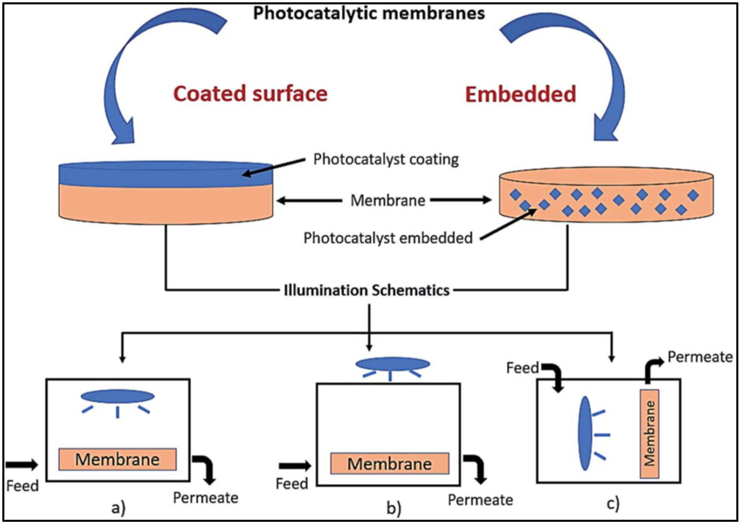
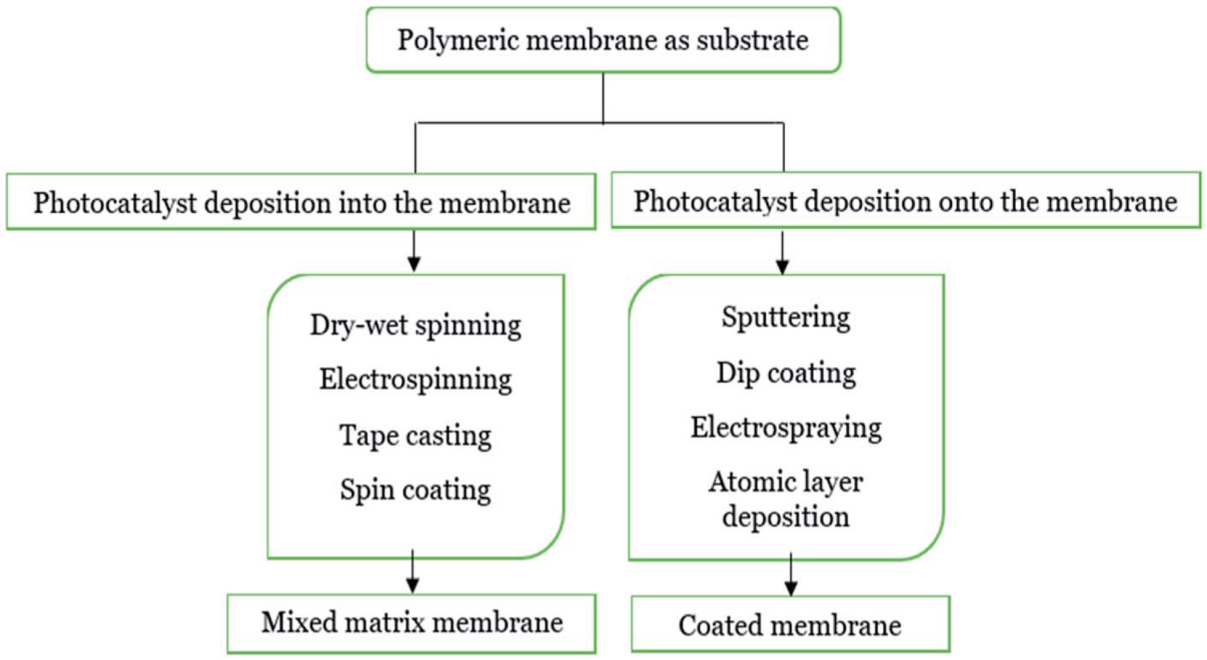
2. Photocatalytic Membranes

One of the challenges of photocatalysis is the presence of suspended photocatalysts during the membrane separation process. Recently, photocatalytic membranes have emerged as a promising solution to this problem. According to Molinari et al., the suspended photocatalyst offers advantages such as a larger surface area, leading to improved photocatalytic effectiveness. The suspended nanosized photocatalyst poses challenges during the recovery process and persists in the water during filtration. As a result, it can lead to membrane fouling, which reduces both the permeate flux and the photocatalytic activity. Additionally, recovering the photocatalyst after the separation procedure may demand expensive treatment and take more time [15].
Before membrane casting, the photocatalyst nanoparticles can either be applied to the membrane surface or dispersed within the polymer dope solution. Other approaches for creating polymeric and ceramic photocatalytic membranes have been suggested and tested (Figure 1). The primary goal is to attach the photocatalyst to the membrane and enhance its photocatalytic activity.
Polymer membranes can be produced using several methods, including electrospinning, sintering, template leaching, stretching, track-etching, and phase inversion. A straightforward method called phase inversion may be implemented to create different kinds of polymers with different membrane layouts. Furthermore, electrospinning facilitates the fast and easy production of membranes with different diameters and structures, despite having a slow membrane yield rate. Other techniques, including sintering and stretching can create durable microfiltration polymeric membranes using specific polymers, such as PE and PTFE. Although there is no solvent used in this process, a greater temperature is required. Furthermore, the track-etching technique is advantageous since it can create polymeric membranes for both microfiltration and ultrafiltration. It also presents a disadvantage due to its costly process, which is similar to that of the template leaching method. Table 1 summarizes the benefits and limitations of these techniques [15].
Ceramic membranes can be produced using several methods, such as slip casting, extrusion, and pressing, among others. The preparation process may be summed up in the phases below:
(a)
Suspension preparation involves combining the starting powders with an appropriate binding liquid.
(b)
Forming entails reshaping the prepared suspension using a predefined technique.
(c)
Heat treatment is the process of sintering membrane particles together at high temperatures.
Regardless of subsequent preparation stages, this fire phase is the most crucial step in the creation of ceramic membranes. Multi-layer membranes can be created by applying the necessary layers (sol–gel, CVD, etc.) to a membrane support before the firing phase [4]. As shown in Figure 2, the manufacture of composite membranes involves coating the membrane support and then burning it.

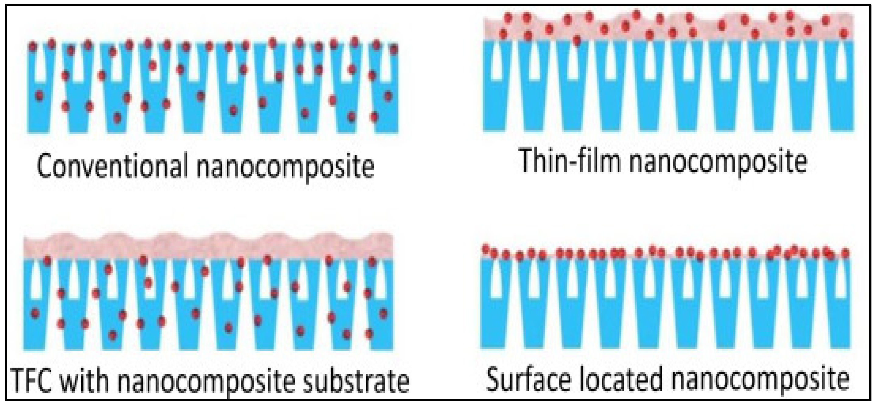
3. Nanocomposite Photocatalytic Membranes

Concentration polarization and membrane fouling are the primary factors that diminish the efficiency of membrane separation. An increased concentration of rejected suspended or dissolved materials near the membrane surface results in concentration polarization. Membrane fouling occurs when the overall performance of the membrane is impaired by the irreversible accumulation of suspended or dissolved particles on its outer surface or within its pores. When a membrane filter becomes fouled, it necessitates challenging and often costly cleaning procedures that disrupt the continuous operation of the membrane filtration process. These methods include forward and reverse flushing, backwashing, air scouring, and back permeation. Although membrane systems may have greater initial or operational costs compared to conventional methods like evaporation, activated carbon, deep-bed filtration, coagulation, sedimentation, or chemical treatment, they generally deliver higher-quality water and have a reduced environmental impact. In an effort to address these issues, a lot of research is being conducted on fouling remediation, which involves enhancing the antifouling capabilities of conventional membranes [3]. Recently, a brand-new area of research with a membrane modification focus has arisen. One such breakthrough is tinkering with the properties of membranes using nanomaterials to optimize performance for particular pollutant types or enhance fouling resistance.
Nanocomposites are materials that contain one or more nanoscale-sized phases contained inside a matrix phase. To create smart materials that meet or exceed the original design expectations, it is essential to optimize the interactions between different phase components during the fabrication process [16].
Nanoparticles integrated into membrane matrices or coated onto their surfaces have been utilized to enhance membrane functionality, enabling them to selectively capture specific pollutants or facilitate degradation reactions. The resulting mixed matrix membranes (MMMs) have multiple uses in the treatment of water [16]. The properties of the hybrid material are determined by various factors, including nanomaterial loading, matrix composition, particle dispersion, nanoscale phase size, shape, and orientation, as well as the interactions between different phases. To enhance the properties of the resulting polymer, nanoscale inorganic photocatalysts are incorporated into the membrane matrices in photocatalytic membranes.
The initial efforts to integrate photocatalysis with membrane technology aimed to isolate and utilize photocatalysts. This method, however, faced common problems such as membrane fouling, photocatalyst deactivation, and nanoparticle aggregation. This sparked curiosity in developing standalone hybrid photocatalysis/filtration water treatment technologies that were effective at both separation and photocatalysis. One of the advantages of these innovations is the lack of any post- or pre-treatment stages, making it an attractive option for scaling up the technique in membrane wastewater treatment applications [17].
TiO2 has become one of the most promising and active photocatalysts for heterogenous photocatalysis and advanced oxidation processes due to its stability, low cost, availability, non-toxicity, unique photocatalytic efficiency, and potential applications in water and wastewater treatment [18]. Recently, various methods have been developed and improved for the production of TiO2-based photocatalytic membranes. These methods involve anodizing titanium films deposited onto stainless steel substrates, incorporating TiO2 nanoparticles into the polymer membrane matrix, and applying coatings to porous supports through dipping or spinning with TiO2 precursor sols. TiO2 nanofibers are also passed through glass filters before undergoing hot pressing or liquid phase pressurization [18]. It also includes, among other processes, the creation of free-standing and flow-through TiO2 nanotube membranes, the electrospinning of TiO2 nanotube fibers or flat membranes, the fast atmospheric plasma spray coating of TiO2 layers, and the electrospinning of TiO2 fibers or flat membranes [17]. Based on where the nanoparticles are located on the membrane, photocatalytic membranes may be roughly divided into four kinds [19] (Figure 3):
  • Standard nanocomposites;
  • Nanocomposites with thin films (TFCs);
  • Nanocomposite thin film on a nanocomposite substrate;
  • Nanocomposites with a surface-based position.

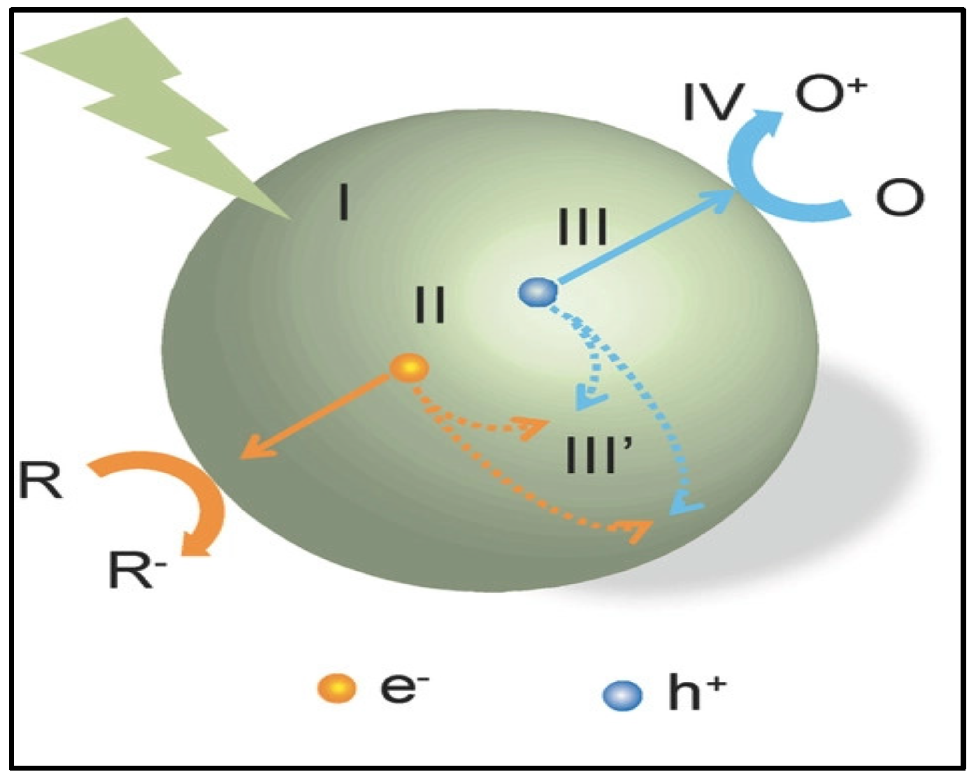
4. Photocatalysis Against Water Pollutants

There are two categories of photocatalysts: homogeneous and heterogeneous photocatalysts. Homogenous photocatalysis, according to Baruah et al. [18], happens when the photocatalyst and medium interact within the same phase, whereas in heterogeneous photocatalysis, they react in different phases. Heterogeneous photocatalysis is preferred over homogeneous photocatalysis as the applied catalyst can be more easily separated after use. Furthermore, the heterogeneous photocatalyst uses renewable solar energy, which promotes green technology to address environmental issues, making it more successful in the removal of pollutants [21]. For instance, in heterogeneous photocatalysis, a solid-phase photocatalyst and a reactive pollutant in the liquid phase can be easily adsorbed and decomposed. The photocatalytic reaction is important as it harnesses solar energy to generate additional charge carriers, enhancing their utilization in the redox process [22]. The ideal photocatalyst for this method should exhibit strong photocatalytic performance, including efficient separation of photogenerated charge carriers, broad light absorption, enhanced stability, and reusability [21]. The efficiency of the degradation process, however, could be influenced by factors such as the charge carrier recombination rate, lower reduction potential, and photocorrosion [23].
The photocatalytic reaction theory suggests that, depending on the specific energy band gap, photoexcitation by visible light, UV light, or infrared light must proceed through a redox process. Equations (1)–(8) provide an example of the fundamental theory behind the photocatalytic process [15]. When light energy is absorbed by the photocatalyst, electrons (e) in the valence band (VB) are excited to the conduction band (CB), creating holes (h+) in the VB [24]. Water undergoes splitting into oxygen (O2) and hydrogen (H+) as a result of the electron being photoexcited, creating holes in the process. A semiconductor absorbs energy that is equal to or greater than its band gap. Water splitting occurs in three steps, beginning with energy absorption and the generation of electrons (e) and holes (h+) through photoexcitation [15]. The second step involves charge separation on opposite sides with minimal recombination, while the final step consists of charge carriers driving oxidation at the valance band (VB) and reduction at the conduction band (CB). A hydroxyl radical is created when holes in water oxidize toward the hydroxyl ion, degrading the pollutant and generating CO2 and H2O in the process. Figure 4 shows a schematic representation of the fundamental photocatalysis for better comprehension. It explains how the photocatalyst interacts with light to degrade pollutants, resulting in water purification.
e (CB) + h+ (VB)/energy
H2O + h+ (VB)/cOH + H+
O2 + e (CB)/O2c_
cOH + pollutant/H2O + CO2
O2c_ + H+/cOOH
cOOH + cOOH/H2O2 + O2
O2c_ + pollutant/CO2 + H2O
cOOH + pollutant/CO2 + H2O
When selecting a photocatalyst for light-induced reactions, key factors include physical and chemical stability, cost-effectiveness, availability, oxidative capacity, and non-toxicity [5]. Titanium dioxide (TiO2), either in suspended form or integrated into or onto the membrane, is the most widely studied and notable photocatalyst in the literature [15]. The majority of prior research teams have chosen TiO2 as a photocatalyst owing to its increased catalytic activity, stability across a wide pH range, and well-known characteristic as a cost-effective material. Due to TiO2’s greater band gap, it can be utilized as a photocatalyst when exposed to UV light at wavelengths less than 400 nm [26]. For the same reason, it cannot be employed under visible light illumination. This problem can be addressed by doping TiO2 with a narrow-band-gap photocatalyst or utilizing a small-band-gap photocatalyst alone for reactions under visible light. It is possible to utilize photocatalysts with configurable band gaps, including ZnO, Cu2O, Ag, Bi2O3, carbon nanotubes, and others [27].
Using clean, renewable solar energy, photocatalysis serves as an excellent substitute for energy-saving treatment techniques. Various hazardous substances can be destroyed as a result of the procedure, creating safe products in the process. The reaction state also produces little secondary waste and needs little chemical input. Photocatalysis is not just useful for treating water; it can also be used to produce hydrogen and treat solid and gaseous phases of media. Charge separation, interfacial charge transfer, and prevention of charge carrier recombination are additional difficulties in photocatalysis [28].
The chemical and physical characteristics of both the photocatalyst and the polymeric membrane play a crucial role in determining their interaction [15]. Understanding the interaction between the photocatalyst and the polymeric membrane is essential for a membrane-binding photocatalyst. Rasch et al. investigated the interaction between gold (Au) nanoparticles and the cell membrane [29]. The hydrophobic zone was seen to be penetrated and embedded by Au nanoparticles (L-α-phosphatidylcholine). The energy applied in this process led to the accumulation and incorporation of nanoparticles on one side of the vesicle, as illustrated in Figure 5. Moreover, considering the strong pushing force driving nanoparticle insertion, the increased number of embedded nanoparticles in the bilayer can be explained. The diameter of the nanoparticle and the liquid–vapor surface tension of the water are denoted by D and γ, respectively. The free energy change (ΔGsolv) required for hydrophobically modified Au nanoparticles to transition from the water phase into the hydrophobic cell membrane was found to be πD2γ. The accumulation of nanoparticles and the cell membrane may lead to the formation of cavities around individual nanoparticles [29].
The clustering phenomena that result from the voids attracting other nanoparticles may be referred to as the interparticle interaction [30]. Additionally, it is suggested that the nanoparticle clustering during the heating process results from strong Vander Waals forces. According to the attractive forces in the fluid phase and the repulsive forces in the gel phase, the implanted nanoparticles spontaneously cluster during heating and decluster during cooling. Additionally, one of the contact modalities between the photocatalyst and polymer membrane may be adsorption or the charge of the particle. To enable electrostatic interaction, the photocatalyst and membrane must carry opposite charges. Consequently, the nanoparticles may either become embedded within the polymeric membrane or attach to its surface. According to Chen et al. [31], electrostatic attraction plays a key role, as a positively charged polymer interacting with a negatively charged nanoparticle enhances stiffness and alters permeability.
The shape of the interaction is significantly affected by the charge and size of the components when nanoparticles come into contact with a polymeric membrane [32]. Additionally, the better stability of the nanoparticles may be the cause of their larger loading through adsorption or absorption into the polymeric membrane [33]. Different behavior may be seen when the polymeric membrane interacts with nanoparticles up to 100 nm in size. The claim states that hydrophilic nanoparticles are attached to or embedded within the membrane, while hydrophobic nanoparticles can only be slowly integrated into the membrane due to damage occurring when a higher nanoparticle load is applied [34].
Krack et al. [35] state that the mass ratio of the nanoparticles is r = mn/mp, where mn stands for the nanoparticle and mp for the polymer. To avoid the agglomeration of the polymer and nanoparticles, the essential ratio, r*, should be less than 0.2 to 0.3. As shown in Figure 6 below, the decoration of the polymeric membrane interface with nanoparticles could result in the formation of a bridge linking one bilayer to an adjacent bilayer, which leads to bilayer pairing [36]. Additionally, the introduction of the hydrophobic nanoparticles had a tendency to thicken the membrane and improve its mechanical strength. Due to their hydrophilicity, polymeric membranes have been extensively used in earlier research to include the photocatalyst to reduce fouling, give strength, and boost permeability [37]. According to earlier studies, the perm-selectivity and temperature fluctuations caused the polymeric membrane to become more stable when particles or a catalyst were included into the matrix of the polymer. Additionally, the postseparation barrier related to the powdered photocatalyst can be eliminated by immobilizing the photocatalyst onto a support, like a polymeric membrane. Consequently, the polymeric membrane can both support the photocatalyst and act as a membrane barrier for pollutant removal, thereby enhancing the effectiveness of the photocatalytic technology. Figure 7 illustrates the immobilized photocatalyst on the surface-coated and embedded membrane, along with a depiction of the light illumination. Figure 8 displays the general flow chart for the study’s immobilized photocatalyst approach using a polymeric membrane. Deposition can be performed in one of two ways: into or onto the substrate. Deposition onto the substrate membrane is termed a coated membrane, whereas deposition within the membrane is referred to as a mixed matrix membrane. This work will cover the deposition of the photocatalyst into the polymeric membrane using methods such as dry–wet spinning, electrospinning, tape casting, and spin coating. At the same time, sputtering, dip coating, electro spraying, and atomic layer deposition are employed to apply the photocatalyst on the membrane’s surface [15].

5. Electrocatalytic Membranes

The electrocatalysis method usually employs conventional flat-plate electrodes to activate electrochemical reactions that lead to the catalysis of pollutants. It is however possible to utilize membrane-based electrodes. Electrocatalytic membranes (EMs), in such systems where the membrane surface is the reactive surface, employ both membrane technologies and electrochemical mechanisms to combat water pollutants with a variety of processes; electrosorption, electrochemical oxidation, and membrane filtration are the three primary electromigration (EM) processes for the removal of micropollutants [38].

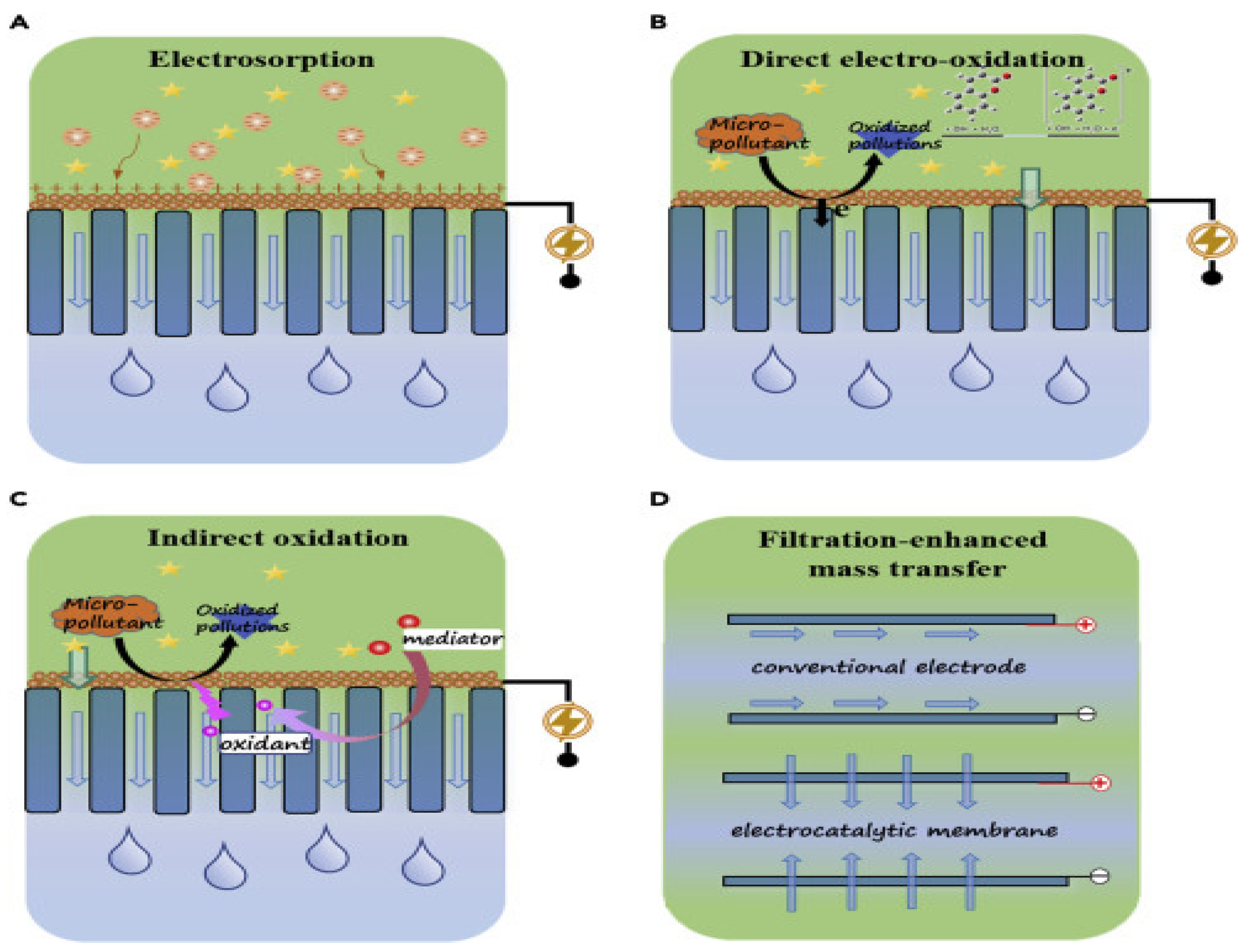
5.1. Electrosorption

The physical sorption mechanism known as electrosorption (Figure 9A) does not entail an electron transfer reaction. Furthermore, electromigration could promote the selective movement of charged micropollutants toward the electrode with the opposite charge for electrosorption. Diffusion, convection, and other processes can also take place in the EM. A critical factor governing the adsorption and elimination of micropollutants is the electrostatic interaction between the pollutant molecules and the surfaces of porous electrode materials. The removal efficiency is strongly dependent on the physicochemical characteristics of the electrode materials—including specific surface area, pore structure, and surface electronic properties—as well as the ionization behavior of the micropollutants [39]. As previously reported [40], electrosorption enhances anodic electrocatalytic membrane processes by facilitating the removal of negatively charged micropollutants, such as per- and polyfluoroalkyl substances (PFASs), antibiotics, and pharmaceuticals containing acidic functional groups.

5.2. Electrochemical Oxidation

The main method for removing micropollutants in electrocatalytic membrane-based systems is electrochemical oxidation. Figure 9B,C illustrate two more categories for electrochemical oxidation processes: (1) direct electro-oxidation and (2) indirect oxidation methods [41]. It is noteworthy that the electrochemical oxidation efficiency of micropollutants in EM surpasses that of the conventional flat-plate electrodes, primarily due to the enhanced mass transfer facilitated by the filtration process within the EM system (Figure 9D) [42].

5.2.1. Direct Electro-Oxidation

In a direct electro-oxidation process, electrons are directly transferred from the micropollutants to the surface of the electrocatalytic membrane. The micropollutants, after being immediately oxidized to intermediates, are then converted to CO2 and H2O. At low potentials, direct electro-oxidation is theoretically feasible. For instance, Zhou et al. [43] demonstrated nearly complete elimination of pyrrole via direct oxidation in a graphite–RuO2–MWCNT filter at 0.3–1.2 V, which is lower than the 1.42 V oxygen evolution potential, with indirect oxidation being more prominent with an anodic potential higher than 1.2 V [43]. However, due to the sluggish reaction rate at low potentials, direct oxidation as a micropollutant removal method is often a lengthy procedure [44]. However, a recent study revealed that noble metals such as Pd can be utilized in direct anodic oxidation with a high electrochemical reaction rate. In the study by Huang et al. [45], amorphous palladium (Pd) was integrated into a Ti4O7 electrode, and the formation of Pd-O bonds was shown to boost the electron transfer rate, thereby promoting the direct oxidation of perfluorooctanoic acid (PFOA).

5.2.2. Indirect Oxidation

While hydroxyl radicals (·OH) are regarded as the main reactive oxygen species for eliminating micropollutants in electrocatalytic membrane processes, the indirect oxidation of these pollutants relies on the formation of powerful oxidizing species (such as ·OH, Cl·, and 1O2) within the electrocatalytic membrane system (Figure 10). Feng and Johnson suggested that water electrolysis processes generate adsorbed ·OH, which can oxidize micropollutants via an oxygen-transfer reaction at a high anodic potential [46]. The membrane material and electrode voltage both affect how well micropollutants are removed during hydroxyl radical-mediated oxidation. According to the literature, “active” and “nonactive” membrane materials can be differentiated when the electrochemical membrane is used as an anode [44]. Because “active” membrane materials such as carbon, graphite, IrO2, and RuO2 have a low oxygen evolution overpotential, the generated ·OH can further react with the active anode, leading to the partial oxidation of micropollutants. The oxygen evolution overpotential of “nonactive” anodes, such as antimony-doped tin oxide and Ti4O7, is typically high, allowing for the direct mineralization of micropollutants into carbon dioxide. Mart’nez-Huitle et al. [47] reported that “nonactive” anodes, such as Ti4O7 (with an oxygen evolution potential of 2.2–2.7 V vs. SHE), typically exhibit higher OPE values compared to “active” anodes like carbon, which has an OEP around 1.7 V.
The electro-Fenton process can indirectly produce ·OH with an electrochemical membrane as a cathode [48]. In the electro-Fenton process, a two-electron oxygen reduction is employed to transform dissolved oxygen into H2O2, and the resulting H2O2 then combines with Fe(II) to generate ·OH. Fe(II) dose and H2O2 yield are essential for the production of ·OH. A 3D flow carbon-based cathode can enhance the production of H2O2 [49]. Since the electro-reduction of Fe(III) on the membrane generates some Fe(II), the electro-Fenton process requires less Fe(II) compared to the traditional Fenton process [48]. When stainless steel wire mesh is used as the cathode, Fe(II) can be generated in situ via a Fe(III)/Fe(II) redox cycle on the membrane surface. The resulting Fe(II) then reacts with H2O2 to efficiently produce ·OH [50].
When chloride ions are present in wastewater, anodic oxidation of chloride ions on the anode can generate reactive chlorine species (RCS), including chlorine radicals (Cl·, Cl2·) and free chlorine (Cl2, HClO, ClO) [51]. Platinum or metal oxides (such as RuO2 or IrO2) are commonly used to construct in situ active chlorine electrodes because of their excellent electrocatalytic properties for chlorine evolution [52]. Sulfamethoxazole, sulfamethazine, paracetamol, and other micropollutants have reportedly been removed using active chlorine-mediated oxidation [53]. However, in certain situations, harmful chlorine-containing organic compounds (e.g., chloroform) and chlorine–oxygen byproducts (such as ClO2 and ClO3) can be formed simultaneously.
In some cases, toxic chlorine organic derivatives (such as chloroform) and chlorine–oxygen byproducts (like ClO2 and ClO3) are also produced at the same time [54].
Singlet oxygen (1O2), an oxygen derivative, is one of the most potent reactive oxygen species. According to Zhao et al. [55], the superoxide-mediated chain reaction and the cathodic activation of persulfate are major methods of 1O2 production from electrically excited precursors (such as O2· and H2O2) [56]. Recent research on EM has demonstrated that singlet oxygen (1O2) can effectively eliminate micropollutants such sulfamethoxazole, carbamazepine, nitrobenzene, diclofenac, and tetracycline, due to its high reactivity and excellent selectivity [57].

5.3. Filtration-Boosted Mass Transfer

In the conventional electrode oxidation method, the standard batch or flow-by operation results in the formation of a thick (100 µm) diffusion boundary layer [58]. In this approach, the efficiency of micropollutant removal is limited by the rate at which contaminants diffuse to the electrode surface. Based on the steady-state balance between convection and diffusion, the theoretical membrane pore radius exceeds the thickness of the diffusion boundary layer. In flow-through mode, the mass transfer of micropollutants from the bulk solution to the electrode surface is enhanced by convection, leading to a mass transfer rate increase [59]. For example, Chen et al. showed that using an electrocatalytic membrane, a 10.3-fold improvement in the removal of 2-methyl-4-isothiazolin-3-one was observed under flow-through conditions relative to flow-by conditions. This significant improvement was attributed to enhanced mass transfer due to convection through the membrane in the flow-through setup, which accelerated the reaction kinetics [60].

6. Applications of Electrocatalytic Membranes for Micropollutant Removal

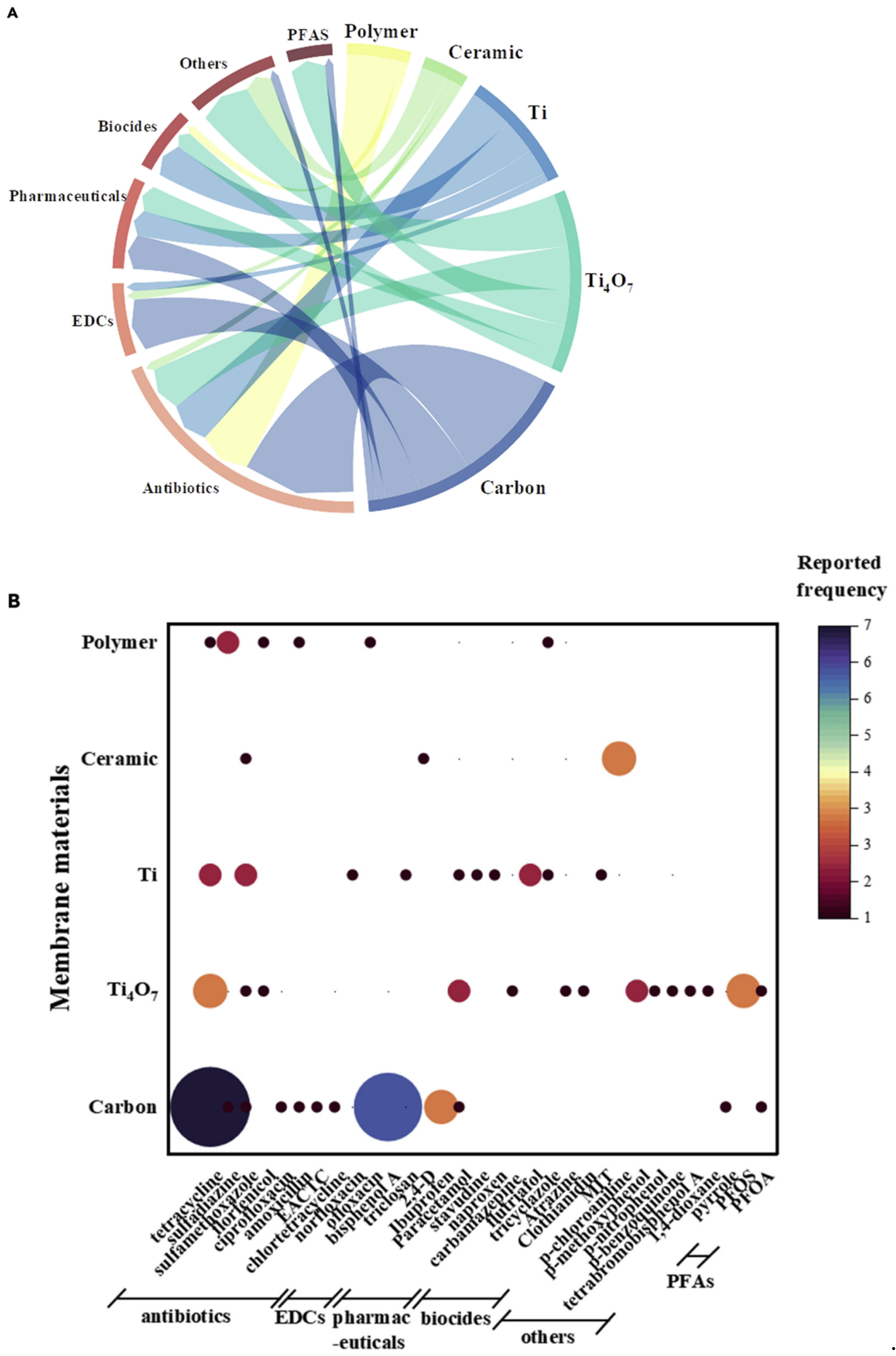
6.1. Membrane Materials

The characteristics of electrocatalytic membrane materials have a significant impact on the effectiveness of micropollutant removal and electrochemical oxidation [38]. At the moment, the most common types of electrode membranes are microfiltration membranes made of carbon-based, porous-Ti, magnetic-phase (mostly Ti4O7), electrochemical ceramic, and polymer composite materials. This section outlines the application and operational parameters of different electrode membrane materials used for micropollutant removal [38].

6.1.1. Carbon-Based Electrocatalytic Membranes

Carbon-based electrocatalytic membranes have been widely used for micropollutant degradation due to their ease of synthesis, high specific surface area, excellent conductivity, and superior mechanical strength [61]. A brief overview of the ability of carbon-based electrocatalytic membranes to remove micropollutants will be discussed. As demonstrated, most carbon-based electrocatalytic membranes show significant removal efficiencies for drugs, endocrine disruptors, antibiotics, and other compounds. Additionally, carbon nanotubes (CNTs) are the predominant carbon-based material utilized in electrocatalytic membrane processes.
Tetracycline [62,63], sulfadiazine [64], sulfamethoxazole, ciprofloxacin and ampicillin [65], and 4-epianhydro-chlortetracycline [66] may all be removed using carbon-based electrocatalytic membranes. For instance, a carbon nanotube (CNT)-based electrochemical filter achieved over 99% removal of tetracycline at a cell potential of 2.5 V and a flow rate of 1.5 mL/min (HRT of 2 s). In a separate study, a newly developed carbon membrane coated with micro-sized antimony-doped tin dioxide (Sb-SnO2) reached a tetracycline removal efficiency of up to 96.5% after 6 h of operation. In addition, a CNT-based electrocatalytic filter showed high efficiency in removing 4-epianhydrochlortetracycline—a hydrolysis byproduct of tetracycline—with a removal rate of 96.8% [66]. Tan et al. designed an electrochemical membrane incorporating multi-walled carbon nanotubes (MWCNTs) to target a range of antibiotics, achieving removal efficiencies of 90% for sulfamethoxazole, 99% for ciprofloxacin, and 75% for amoxicillin, respectively [65].
A common endocrine disruptive substance known as bisphenol A (BPA) is a crucial monomer for the synthesis of adhesives and plastics [67]. BPA has the potential to seriously harm the endocrine system even at concentrations of only a few ng/L [68]. Recent studies have shown the high effectiveness of carbon-based electrocatalytic membranes in removing BPA [67,69,70]. For instance, Pan et al. reported the development and use of a novel electrochemical microfiltration membrane fabricated from coal-derived carbon materials [71]. The BPA and COD removal efficiency (wastewater containing 50 mg/L) were up to almost 97 and 90%, respectively, while ibuprofen, paracetamol, and other drugs were also removed using electrocatalytic membranes made of carbon [72]. At a low applied voltage of 2 V, the membrane composed of carboxylated multi-walled carbon nanotubes (MWNTs-COOH) effectively removed nearly all of the ibuprofen [73]. By using a carbon-based membrane as the cathode in a dynamic cross-flow electro-Fenton (DCF-EF) system, Olvera-Vargas et al. were able to completely degrade paracetamol and obtain 44% mineralization [72].

6.1.2. Porous Ti-Based Electrocatalytic Membranes

High porosity, great corrosion resistance, superb conductivity, and remarkable biocompatibility are all characteristics of porous titanium [74]. The composite membrane can exhibit high electrocatalytic activity by applying catalysts such as IrO2, RuO2, PbO2, and doped SnO2 onto the surface of porous Ti [75,76], which has been extensively used for removing micropollutants, including biocides, antibiotics, pharmaceuticals, and endocrine disruptors. Qian et al. [77] described a titanium-based membrane (TiO2NTA) for the removal of triclosan pollutant, with 99.80% removal.
Tetracycline, sulfamethoxazole, and norfloxacin were successfully removed at high concentrations (>90%) using electrocatalytic membranes based on titanium. For instance, Yang et al. designed a novel ultrahigh-throughput tubular filter coated with β-PbO2, which efficiently removed trace levels of norfloxacin and sulfamethoxazole from both surface water and wastewater effluent, achieving this within a short residence time of 2.0 to 5.4 s [78]. Ren et al. developed an innovative reactive electrochemical layer on a palladium-loaded porous titanium anode, where singlet oxygen was directly produced on the anode via Pd-O2 interaction, resulting in an exceptionally fast and efficient anodic oxidation of the trace antibiotic sulfamethoxazole [79].
Using electrocatalytic membranes made of titanium, biocides have also been eliminated. Liu et al. have engineered an electrochemical membrane made from Ti and 3D ordered macroporous PbO2 that effectively removed flutriafol (75%) from the mixture [80]. Tricyclazole was eliminated using an electrochemical membrane made of porous Ti that was filled with RuO2. The elimination effectiveness of tricyclazole was around 78.4% under the ideal circumstances (3 mA/cm2) [81]. In a different study, Chen et al. designated an innovative electrocatalytic membrane to remove 2-methyl-4-isothiazolin-3-one, initially developed by creating a TiO2 nanotube array on a macroporous Ti substrate. Next, they coated the substrate with SnO2-Sb2O3 [82]. The removal effectiveness was around 80% [60].
By the same token, drugs can be eliminated using an electrocatalytic membrane made of porous Ti. The Ti-based membrane doped with Sb-doped SnO2 has been used for removing common antiretroviral drugs, such as stavudine and tetracycline, due to its low cost, easy fabrication, and strong catalytic activity [83]. Additionally, Xu et al. developed a porous Ti/SnO2-Sb/Ce-PbO2 membrane for degrading naproxen in aqueous solution, achieving a removal rate of nearly 100% at a current density of 10 mA/cm2 [84].

6.1.3. Electrocatalytic Membranes Based on Magnéli Phase

Titanium (Ti4O7) in the Magnéli phase, recognized for its outstanding chemical stability, high electrical conductivity, and cost-effective production, has garnered significant attention in recent years for its application in electrocatalytic membranes (EMs) [85,86,87]. Previous studies have shown that the Ti4O7 electrode can function as an active electrode for the direct oxidation of pollutants or as an inactive electrode for the indirect oxidation of pollutants through OH radicals. A brief summary on the effectiveness of the elimination of micropollutants using an a Magnéli-phase-based electrocatalytic membrane has been discussed [38]. A removal efficiency of over 90% can be achieved for most micropollutants, including pharmaceuticals, antibiotics, biocides, PFAS, and p-substituted phenol, via the Magnéli-phase-based electrocatalytic membrane.
When a wastewater treatment facility’s secondary effluent, which contains 100 g/L of carbamazepine, is treated, degradation of carbamazepine can reach high levels (>98%), with a mineralization efficiency of 70% [88]. Trellu et al. assessed the performance of a newly developed TiOx membrane, synthesized via the carbothermal reduction of TiO2, by using paracetamol as a model contaminant. The elimination efficiency of paracetamol was greater than 99.9% at the ideal existing density (6 mA/cm2) [59]. The intermediate paracetamol product, 1,4-benzoquinone, presents a considerable barrier to direct electron transfer, making the mineralization process more challenging. The mineralization efficiency increased to 77% when the Trellu research group combined a TiOx membrane anode with a cathodic electro-Fenton process, which worked together to breakdown paracetamol into intermediate compounds like carboxylic acids [89]. Furthermore, antibiotics can be removed using the porous Magnéli phase Ti4O7 anode, achieving removal efficiencies greater than 95% (e.g., Tetracycline, sulfamethoxazole [86,90]). The degradation of antibiotics was mainly facilitated by hydroxyl radicals targeting the antibiotics’ double bonds, as well as their phenolic and amine functional groups [91]. Ozonation and a Ti4O7 electrochemical membrane can lead to the complete elimination of Tetracycline in less than 20 min (mineralization efficiency of 77% in ideal circumstances) [92].
The high generation of OH radicals in the Magneli-phase-based membrane coated with bismuth-doped tin oxide (BDTO) catalysts enhances the efficiency of pesticide mineralization. In just 3.6 s (at a flux of 600 L m−2 h−1) and an applied potential of 3.5 V versus SHE, the Magnéli-phase electrocatalytic membrane accomplished full mineralization of the pollutants atrazine (ATZ) and clothianidin (CDN) [93].
Due to its extensive electrochemical behavior, Magnéli-phase-based electrocatalytic membranes were utilized to eliminate PFAs [42]. At an anodic potential ranging from 3.7 to 3.9 V against SHE, the porous Ti4O7 electrocatalytic membrane can efficiently eliminate perfluorooctanoic acid (PFOA) with over 99.9% removal [42] and perfluorooctane sulfonate (PFOS) with 93.1% of removal [94]. It has also been noted that the reaction can be driven by OH radicals produced via water oxidation, initiated by direct electron transfer at the anode, leading to the formation of PFOS free radicals during the breakdown of PFOS [95].
The porous Ti4O7 electrocatalytic membrane may also be used to efficiently extract p-substituted phenol. Removal efficiencies exceeding 98% reported for both p-methoxyphenol and p-nitrophenol, mostly accomplished by electrochemical adsorption and OH oxidation [96]. Meanwhile, the removal of tetrabromobisphenol A and 1,4-dioxane micropollutants using fluorinated titanium suboxide (TiSO) (removal efficiency 99.70%) [97] and GO/Fe3O4/Ti4O7 [98] electrocatalytic membranes has been reported.

6.1.4. Electrochemical Ceramic Membranes

Ceramic membranes are characterized by high water permeability and strong mechanical strength. Al2O3 and ZrO2 are commonly used ceramic membrane materials, but they are non-conductive. Therefore, electrochemical ceramic membranes are usually made by either integrating electrode materials into the ceramic membranes or by applying a coating of electrocatalytic materials onto their surfaces [99]. Widely employed for the removal of micropollutants, electrochemical ceramic membranes exhibit excellent electrochemical corrosion resistance. For endocrine disruptors, antibiotics, and aniline chemicals, the electrochemical ceramic membrane typically demonstrates good removal efficiency, with elimination efficiencies between 62% and 100% when a voltage of 1.6 to 3.0 V is applied.
Para-Chloroamphetamine PCA, a chlorinated aromatic amine molecule, has been eliminated using an electrochemical ceramic membrane. Zheng et al. used a TiO2@SnO2-Sb anode to develop a new electrochemical ceramic microfiltration membrane. The removal efficiency of PCA was 85.5% under ideal circumstances (3 V working voltage and 17.4 L/(m2h) membrane flow), and the majority of the breakdown products were harmless short-chain carboxylic acids, such as formic, acetic, and oxalic acids [100]. High PCA elimination efficiency was also demonstrated by Xu et al., who used the Ti/RuO2 electrocatalytic’s membrane. At 2.0 V of power, PCA had an 87.1% elimination efficiency [101]. For the elimination of PCA, a cathodic electrochemical membrane technique in conjunction with an electro-Fenton procedure was also employed. PCA was entirely broken down at pH 3 and 0.2 mM Fe2+ addition, and mineralization efficiency was 75.1% [102]. Furthermore, by combining a ceramic membrane with a molecularly imprinted TiO2@SnO2-Sb anode, selective removal of 2,4-dichlorophenoxyacetic acid was achieved, reaching a removal efficiency of 63.6% [82]. Utilizing confocal co-sputtering, Zhao et al. constructed a Pd–Pt–ceramic membrane that can remove 82.9% of sulfamethoxazole using the singlet oxygen produced during the electrocatalytic reaction [55].

6.1.5. Polymer Composite Membranes

Electrocatalytic membranes are also fabricated using conductive polymers like polyaniline (PANI) and polypyrrole (PPy) because of their conjugated molecular structures, hydrophilic nature, and comparatively high electrical conductivity [103]. For example, Liu et al. developed a conductive polymer composite membrane by blending polyaniline (PANI) and polyimide (PI), with both polymers doped using sulfosalicylic acid [104]. Support layers composed of stainless steel or titanium mesh can be used in conductive polymer composite membranes [105]. As an illustration, a composite membrane was employed by Zheng and co-workers to remove sulphanilic acid (>80% removal efficiency) by incorporating a stainless-steel mesh into the active layer of a polyvinylidene fluoride (PVDF) microfiltration membrane. The OH radicals produced through the Fenton reaction were responsible for degrading the sulphanilic acid [50]. The elimination of sulfadiazine from surface water was claimed to have produced similar results (79% removal efficiency) [106]. Jiang et al. created a polytetrafluoroethylene (PTFE) membrane that has been electro-Fenton catalytically modified with graphene for the breakdown of antibiotics [48].
The interaction between different electrode membrane materials and the target micropollutants was examined in accordance with the literature survey (Figure 11) [38]. Carbon-based electrocatalytic membranes are among the most commonly used membranes for removing micropollutants due to their excellent electrical conductivity and adsorption capacity. These membranes are mainly used to remove pharmaceuticals, endocrine-disrupting compounds, and antibiotics. However, due to the low standard potential for carbon oxidation (0.207 V vs. SHE), carbon-based electrocatalytic membranes are susceptible to the degradation of carbon materials when exposed to high anodic potentials [38]. Consequently, carbon-based electrocatalytic membranes are generally operated at relatively low applied voltages, typically around 3 V. Ti-based and Magnéli-phase electrocatalytic membranes are commonly utilized for eliminating antibiotics, endocrine disruptors, pharmaceuticals, pesticides, PFAs, and other micropollutants due to their outstanding mechanical strength and electrochemical stability [38]. Among them, Ti4O7 has a high potential for oxygen evolution and can interact with a variety of micropollutants over a broad spectrum of redox potentials. Electrochemical ceramic composite membranes and polymer composite membranes are mainly employed for the removal of antibiotics and aniline compounds because of their high hydrophilicity and porous structure.

7. Summary and Future Work

This review provides a concise overview of the various photocatalytic/electrocatalytic membranes and the distinct methods by which they catalyze pollutant degradation. For photocatalytic systems, studies have shown that doping with some earth-abundant transition metals is more successful than doping with noble metals. In comparison, earth-abundant and noble transition metals are expensive and toxic, while photocatalysts modified from non-metal and metalloid elements are inexpensive and safe for the environment. Each element produces a photocatalyst with its own set of characteristics, and the synthesis technique may be expanded to tailor the photocatalyst’s spectrum in order to boost its photocatalytic activity. Clay and biomass, two eco-friendly photocatalytic supporting materials, have been demonstrated to dramatically boost photodegradation efficacy using an easy-to-implement synthesis approach. The sol–gel technique seems to be the most common approach for producing biomass-based photocatalysts because of its low sintering temperature, great adaptability of processing, excellent homogeneity at the molecular level, and lower energy requirements. Carbon from biomass should not be leached into wastewater, since this might lead to the introduction of a secondary pollutant.
In the field of electrocatalytic membrane systems, micropollutants in water and wastewater may be effectively removed with EMs thanks to electrocatalytic oxidation and improved mass transfer. Several studies have been published in the past several years on micropollutant removal using electrocatalytic membranes; however, the technology is still in its infancy with respect to actual implementation. There are a few major problems that require fixing before electrocatalytic membranes can be widely used for micropollutant removal. Certain intermediates can be as harmful as, or even more toxic than, the parent chemicals, even when micropollutants are oxidized through direct oxidation or by strong oxidants (e.g., OH, 1O2). Furthermore, electro-oxidation can produce harmful by-products, including perchlorate and halogenated organic compounds. Thus, the performance of electrocatalytic membranes should be assessed by taking into account the generation of intermediate products and the toxicity of by-products. In addition, enhancing electrocatalytic membranes’ mineralization performance is critically crucial. The effectiveness and affordability of electrocatalytic membrane-based processes are significantly impacted by the material of the membrane used. Despite their widespread use, CNT and Ti-based membrane materials remain too expensive for large-scale application. Filtration encounters difficulties because loaded catalysts like Pb and Sb can leach into the solution. As a result, research on durable, economically viable, and stable membrane materials that can be used in EMs is essential. Electrocatalytic membrane preparation techniques are currently somewhat involved and limited to the laboratory setting. For instance, Magnéli-phase titanium oxides need a lengthy reduction period at a certain pressure during the synthesis process. That is why it is crucial to find a way to efficiently prepare electrocatalytic membranes for use in large-scale production, since this will allow the technology to be used in real-world wastewater treatment applications. Electrochemical nanofiltration and reverse osmosis procedures are rather rare in comparison to electrochemical microfiltration/ultrafiltration, as discussed in the Section 6.1. It is important to learn more about how well electrochemical advanced oxidation technology may work when coupled with nanofiltration and reverse osmosis membranes. Integrating biological processes with electrocatalytic membrane filtration presents promising opportunities to improve the elimination of micropollutants. While offering valuable insights into (1) the mechanisms by which electrocatalytic membranes remove micropollutants and (2) the optimization of removal efficiency through the adjustment of operating conditions, laboratory research often faces a gap when it comes to practical applications. Matrix complexity in water reflects actual wastewater conditions. More research is needed into EM’s efficacy and durability in actual wastewater settings. Micropollutant removal using electrocatalytic membranes has only been studied on a small scale. Further testing is needed to ensure the technique can be used at scale.
This review also includes topics such as sol–gel, anodization, LPD, and SEE for the manufacture of photocatalytic membranes. A major benefit of combining photocatalysts with membrane technology is that the photocatalysts may be used in a continuous process, cutting down on operational time and costs by eliminating a separation step. Using various photocatalysts, the photocatalytic membrane’s characteristics may be adjusted. However, because photocatalytic membranes have such a small amount of photocatalyst surface area per unit volume, they are best suited for dealing with pollutants present in dilute concentrations. As an added concern, the polymeric membrane structure containing the photocatalysts may be damaged by exposure to UV light and the action of oxidizing species. It is recommended that more focus be placed on research into the actual treatment of wastewater utilizing inorganic photocatalytic membranes.

Author Contributions

Conceptualization, E.M.E.; methodology, A.M.E.; software, T.M.S.; validation, I.I.; formal analysis, H.S.; investigation, M.M.M., M.H.E., I.I., P.K. and G.V.B.; resources, S.M.A.; data curation, T.M.S. and M.S.A.; writing, I.I. and E.M.E.; review and editing, M.H.E., A.M.E. and I.I.; visualization, T.M.S. and G.G.M.; supervision, T.M.S.; project administration, T.M.S. All authors have read and agreed to the published version of the manuscript.

Funding

This research received no external funding.

Institutional Review Board Statement

Not applicable.

Data Availability Statement

No new data were created or analyzed in this study.

Acknowledgments

The authors would like to thank the staff of the Al azhar university for their cooperation.

Conflicts of Interest

The authors declare no conflicts of interest.

References

  1. Bhayana, P.; Dandekar, T.; Bala, R.; Madaan, R.; Mahajan, P. Role of carbon nanotubes in remediation of pharmaceutical wastewater. Remediation 2024, 34, 21776. [Google Scholar] [CrossRef]
  2. Zhou, H.; Zhou, L.; Ma, K. Microfiber from textile dyeing and printing wastewater of a typical industrial park in China: Occurrence, removal and release. Sci. Total Environ. 2020, 739, 140329. [Google Scholar] [CrossRef]
  3. Kushniarou, A.; Garrido, I.; Fenoll, J.; Vela, N.; Flores, P.; Navarro, G.; Hellin, P.; Navarro, S. Solar photocatalytic reclamation of agro-waste water polluted with twelve pesticides for agricultural reuse. Chemosphere 2019, 214, 839–845. [Google Scholar] [CrossRef]
  4. Molinari, R.; Severino, A.; Lavorato, C.; Argurio, P. Which Configuration of Photocatalytic Membrane Reactors Has a Major Potential to Be Used at an Industrial Level in Tertiary Sewage Wastewater Treatment? Catalysts 2023, 13, 1204. [Google Scholar] [CrossRef]
  5. Jabbar, Z.; Graimed, B.; Ammar, S.; Sabit, D.; Najim, A.; Radeef, A.; Taher, A. The latest progress in the design and application of semiconductor photocatalysis systems for degradation of environmental pollutants in wastewater: Mechanism insight and theoretical calculations. Mater. Sci. Semicond. Process. 2024, 173, 108153. [Google Scholar] [CrossRef]
  6. Ali, Z.; Saif, M.; Nawaz, F.; Fareed, I.; Khan, M.D.; Saif, A. Exploring the catalytic potential of MnO for photodegradation of organic dyes. MRS Adv. 2025. [Google Scholar] [CrossRef]
  7. Acharya, R.; Parida, K. A review on TiO2/g-C3N4 visible-light- responsive photocatalysts for sustainable energy generation and environmental remediation. J. Environ. Chem. Eng. 2020, 8, 103896. [Google Scholar] [CrossRef]
  8. Jo, Y.K.; Lee, J.M.; Son, S.; Hwang, S.J. 2D inorganic nanosheet-based hybrid photocatalysts: Design; applications, and perspectives. J. Photochem. Photobiol. C Photochem. Rev. 2019, 40, 150–190. [Google Scholar] [CrossRef]
  9. Chiu, Y.H.; Chang, T.F.M.; Chen, C.Y.; Sone, M.; Hsu, Y.J. Mechanistic Insights into Photodegradation of Organic Dyes Using Heterostructure Photocatalysts. Catalysts 2019, 9, 430. [Google Scholar] [CrossRef]
  10. Wu, X.; Lu, J.; Huang, S.; Shen, X.; Cui, S.; Chen, X. Facile fabrication of novel magnetic 3-D ZnFe2O4/ZnO aerogel based heterojunction for photoreduction of Cr(VI) under visible light: Controlled synthesis, facial change distribution, and DFT study. Appl. Surf. Sci. 2022, 594, 153486. [Google Scholar] [CrossRef]
  11. Dong, J.; Yu, J.; Deng, P.; Qu, D.; Liu, J.; Ji, X.; Zhang, D.; Pu, X.; Cai, P. Highly efficient Bi/BiOCl with oxygen vacancies photocatalyst with synergetic effects of oxygen vacancy, surface plasmon resonance, and electron sink effects of metallic Bi. Appl. Organomet. Chem. 2024, 38, e7633. [Google Scholar] [CrossRef]
  12. Darowna, D.; Wrobel, R.; Morawski, A.W.; Mozia, S. The influence of feed composition on fouling and stability of a polyethersulfone ultrafiltration membrane in a photocatalytic membrane reactor. Chem. Eng. J. 2017, 310, 360–367. [Google Scholar] [CrossRef]
  13. Ikrari, K.I.; Hasbullah, H.; Salleh, W.N.W.; Nakagawa, K.; Yoshioka, T. Photocatalytic membrane technologies for removal of recalcitrant pollutants. Mater. Proc. 2022, 65, 3101–3108. [Google Scholar] [CrossRef]
  14. Baig, U.; Waheed, A.; Abu-Zahra, N.; Aljundi, I.H. A polymeric-ceramic hybrid membrane with a self-cleaning and super-wettable surface decorated with polypyrrole-G-C3N4 photocatalyst for oily wastewater treatment. Sep. Purif. Technol. 2024, 339, 126487. [Google Scholar] [CrossRef]
  15. Zakria, H.S.; Othman, M.H.D.; Kamaludin, R.; Kadir, S.; Kurniawan, T.A.; Jilani, A. Immobilization techniques of a photocatalyst into and onto a polymer membrane for photocatalytic activity. RSC Adv. 2021, 11, 6985–7014. [Google Scholar] [CrossRef]
  16. Sarkar, S.; Chakraborty, S. Nanocomposite polymeric membrane a new trend of water and wastewater treatment: A short review. Groundw. Sustain. Dev. 2021, 12, 100533. [Google Scholar] [CrossRef]
  17. Wang, C.; Wang, Y.; Qin, H.; Lin, H.; Chhuon, K. Application of Microfiltration membrane Technology in Water treatment. IOP Conf. Ser. Earth Environ. Sci. 2020, 571, 012158. [Google Scholar] [CrossRef]
  18. Shi, F.M.; Ma, Y.X.; Ma, J.; Wang, P.P.; Sun, W.X. An overview on nanostructured TiO2–containing fibers for photocatalytic degradation of organic pollutants in wastewater treatment. J. Water Process Eng. 2012, 389, 522–531. [Google Scholar]
  19. Pasini, S.M.; Valério, A.; Yin, G.; Wang, J.; Souza, S.M.A.G.U.; Hotza, D.; Souza, A.A.U. Development of advanced nanocomposite membranes using graphene nanoribbons and nanosheets for water treatment. J. Membr. Sci. 2021, 40, 101827. [Google Scholar]
  20. Khanlari, S.; Tofighy, M.A.; Mohammadi, T. Transport phenomena through nanocomposite membranes. Micro Nano Technol. 2020, 91–112. [Google Scholar] [CrossRef]
  21. Li, C.C.; Zhang, H.; Wang, F.; Zhu, H.L.; Guo, Y.H.; Chen, M.Y. PVA and CS cross-linking combined with in situ chimeric SiO2 nanoparticle adhesion to enhance the hydrophilicity and antibacterial properties of PTFE flat membranes. RSC Adv. 2019, 9, 19205–19216. [Google Scholar] [CrossRef]
  22. Li, Y.; Jin, C.L.; Peng, Y.L.; An, Q.F.; Chen, Z.P.; Zhang, J.C.; Ge, L.; Wang, S.B. Fabrication of PVDF hollow fiber membranes via integrated phase separation for membrane distillation. J. Taiwan Inst. Chem. Eng. 2019, 95, 487–494. [Google Scholar] [CrossRef]
  23. Cai, T.; Zeng, W.G.; Liu, Y.T.; Wang, L.L.; Dong, W.Y.; Chen, H.; Xia, X.N. A promising inorganic-organic Z-scheme photocatalyst Ag3PO4/PDI supermolecule with enhanced photoactivity and photostability for environmental remediation. Appl. Catal. B Environ. 2020, 263, 118327. [Google Scholar] [CrossRef]
  24. You, J.H.; Guo, Y.Z.; Guo, R.; Liu, X.W. A review of visible light-active photocatalysts for water disinfection: Features and prospects. Chem. Eng. J. 2019, 373, 624–641. [Google Scholar] [CrossRef]
  25. Zhu, S.S.; Wang, D.W.; Principles, B. Diverse Forms of Implementations and Emerging Scientific Opportunities. Adv. Energy Mater. 2017, 7, 1700841. [Google Scholar] [CrossRef]
  26. Ibrahim, I.; Kaltzoglou, A.; Athanasekou, C.; Katsaros, F.; Devlin, E.; Kontos, A.G.; Ioannidis, N.; Perraki, M.; Tsakiridis, P.; Sygellou, L.; et al. Magnetically separable TiO2/CoFe2O4/Ag nanocomposites for the photocatalytic reduction of hexavalent chromium pollutant under UV and artificial solar light. Chem. Eng. J. 2020, 381, 122730. [Google Scholar] [CrossRef]
  27. Singh, R.; Yadav, V.S.K.; Purkait, M.K. Cu2O photocatalyst modified antifouling polysulfone mixed matrix membrane for ultrafiltration of protein and visible light driven photocatalytic pharmaceutical removal. Sep. Purif. Technol. 2019, 212, 191–204. [Google Scholar] [CrossRef]
  28. Madhavi, V.; Kondaiah, P.; Rao, G.M. Influence of silver nanoparticles on titanium oxide and nitrogen doped titanium oxide thin films for sun light photocatalysis. Appl. Surf. Sci. 2018, 436, 708–719. [Google Scholar]
  29. Rasch, M.R.; Rossinyol, E.; Hueso, J.L.; Goodfellow, B.W.; Arbiol, J.; Korgel, B.A. Hydrophobic Gold Nanoparticle Self-Assembly with Phosphatidylcholine Lipid: Membrane-Loaded and Janus Vesicles. Nano Lett. 2010, 10, 3733–3739. [Google Scholar] [CrossRef] [PubMed]
  30. Von White, G.; Chen, Y.J.; Roder-Hanna, J.; Bothun, G.D.; Kitchens, C.L. Structural and Thermal Analysis of Lipid Vesicles Encapsulating Hydrophobic Gold Nanoparticles. ACS Nano 2012, 6, 4678–4685. [Google Scholar] [CrossRef]
  31. Chen, R.; Pearce, D.J.G.; Fortuna, S.; Cheung, D.L.; Bon, S.A.F. Polymer Vesicles with a Colloidal Armor of Nanoparticles. J. Am. Chem. Soc. 2011, 133, 2151–2153. [Google Scholar] [CrossRef]
  32. Houga, C.; Giermanska, J.; Lecommandoux, S.; Borsali, R.; Taton, D.; Gnanou, Y.; Le Meins, J.F. Micelles and Polymersomes Obtained by Self-Assembly of Dextran and Polystyrene Based Block Copolymers. Biomacromolecules 2009, 10, 32–40. [Google Scholar] [CrossRef]
  33. Binder, W.H.; Sachsenhofer, R. Polymersome/silica capsules by ’Click’-chemistry. Macromol. Rapid Commun. 2008, 29, 1097–1103. [Google Scholar] [CrossRef]
  34. Binder, W.H.; Sachsenhofer, R.; Farnik, D.; Blaas, D. Guiding the location of nanoparticles into vesicular structures: A morphological study. Phys. Chem. Chem. Phys. 2008, 10, 7328. [Google Scholar] [CrossRef]
  35. Krack, M.; Hohenberg, H.; Kornowski, A.; Lindner, P.; Weller, H.; Forster, S. Nanoparticle-loaded magnetophoretic vesicles. J. Am. Chem. Soc. 2008, 130, 7315–7320. [Google Scholar] [CrossRef]
  36. Schulz, M.; Olubummo, A.; Binder, W.H. Beyond the lipid-bilayer: Interaction of polymers and nanoparticles with membranes. Soft Matter 2012, 8, 4849–4864. [Google Scholar] [CrossRef]
  37. Al Harby, N.F.; El-Batouti, M.; Elewa, M.M. Prospects of Polymeric Nanocomposite Membranes for Water Purification and Scalability and their Health and Environmental Impacts: A Review. Nanomaterials 2022, 12, 3637. [Google Scholar] [CrossRef]
  38. Ren, L.; Ma, J.; Chen, M.; Qiao, Y.; Dai, R.; Li, X.; Wang, Z. Recent advances in electrocatalytic membrane for the removal of micropollutants from water and wastewater. Iscience 2022, 25, 104342. [Google Scholar] [CrossRef]
  39. Foo, K.Y.; Hameed, B.H. A short review of activated carbon assisted electrosorption process: An overview, current stage and future prospects. J. Hazard. Mater. 2009, 170, 552–559. [Google Scholar] [CrossRef]
  40. Radjenovic, J.; Duinslaeger, N.; Avval, S.S.; Chaplin, B.P. Facing the Challenge of Poly- and Perfluoroalkyl Substances in Water: Is Electrochemical Oxidation the Answer? Environ. Sci. Technol. 2020, 54, 14815–14829. [Google Scholar] [CrossRef]
  41. Wang, X.Y.; Li, F.X.; Hu, X.M.; Hua, T. Electrochemical advanced oxidation processes coupled with membrane filtration for degrading antibiotic residues: A review on its potential applications, advances, and challenges. Sci. Total Environ. 2021, 784, 146912. [Google Scholar] [CrossRef]
  42. Le, T.X.H.; Haflich, H.; Shah, A.D.; Chaplin, B.P. Energy-Efficient Electrochemical Oxidation of Perfluoroalkyl Substances Using a Ti4O7 Reactive Electrochemical Membrane Anode. Environ. Sci. Technol. Lett. 2019, 6, 504–510. [Google Scholar] [CrossRef]
  43. Zhou, X.Z.; Liu, S.Q.; Xu, A.L.; Wei, K.J.; Han, W.Q.; Li, J.S.; Sun, X.Y.; Shen, J.Y.; Liu, X.D.; Wang, L.J. A multi-walled carbon nanotube electrode based on porous Graphite-RuO2 in electrochemical filter for pyrrole degradation. Chem. Eng. J. 2017, 330, 956–964. [Google Scholar] [CrossRef]
  44. Panizza, M.; Cerisola, G. Direct And Mediated Anodic Oxidation of Organic Pollutants. Chem. Rev. 2009, 109, 6541–6569. [Google Scholar] [CrossRef]
  45. Huang, D.H.; Wang, K.X.; Niu, J.F.; Chu, C.H.; Weon, S.; Zhu, Q.H.; Lu, J.J.; Stavitski, E.; Kim, J.H. Amorphous Pd-Loaded Ti4O7 Electrode for Direct Anodic Destruction of Perfluorooctanoic Acid. Environ. Sci. Technol. 2020, 54, 10954–10963. [Google Scholar] [CrossRef]
  46. Feng, J.R.; Johnson, D.C. Electrocatalysis of anodic oxygen-transfer reactions—Fe-doped beta-lead dioxide electrodeposited on noble-metals. J. Electrochem. Soc. 1990, 137, 507–510. [Google Scholar] [CrossRef]
  47. Martinez-Huitle, C.A.; Rodrigo, M.A.; Sires, I.; Scialdone, O. Single and Coupled Electrochemical Processes and Reactors for the Abatement of Organic Water Pollutants: A Critical Review. Chem. Rev. 2015, 115, 13362–13407. [Google Scholar] [CrossRef]
  48. Jiang, W.L.; Xia, X.; Han, J.L.; Ding, Y.C.; Haider, M.R.; Wang, A.J. Graphene Modified Electro-Fenton Catalytic Membrane for in Situ Degradation of Antibiotic Florfenicol. Environ. Sci. Technol. 2018, 52, 9972–9982. [Google Scholar] [CrossRef]
  49. Zhang, C.; Jiang, Y.H.; Li, Y.L.; Hu, Z.X.; Zhou, L.; Zhou, M.H. Three-dimensional electrochemical process for wastewater treatment: A general review. Chem. Eng. J. 2013, 228, 455–467. [Google Scholar] [CrossRef]
  50. Zheng, J.J.; Ma, J.X.; Wang, Z.W.; Xu, S.P.; Waite, T.D.; Wu, Z.C. Contaminant Removal from Source Waters Using Cathodic Electrochemical Membrane Filtration: Mechanisms and Implications. Environ. Sci. Technol. 2017, 51, 2757–2765. [Google Scholar] [CrossRef] [PubMed]
  51. Cho, K.; Qu, Y.; Kwon, D.; Zhang, H.; Cid, C.A.; Aryanfar, A.; Hoffmann, M.R. Effects of Anodic Potential and Chloride Ion on Overall Reactivity in Electrochemical Reactors Designed for Solar-Powered Wastewater Treatment. Environ. Sci. Technol. 2014, 48, 2377–2384. [Google Scholar] [CrossRef]
  52. Martinez-Huitle, C.A.; Panizza, M. Electrochemical oxidation of organic pollutants for wastewater treatment. Curr. Opin. Electrochem. 2018, 11, 62–71. [Google Scholar] [CrossRef]
  53. Chi, Z.X.; Zhao, J.Y.; Zhang, Y.; Yu, H.; Yu, H.B. Coral-like WO3/BiVO4 photoanode constructed via morphology and facet engineering for antibiotic wastewater detoxification and hydrogen recovery. Chem. Eng. J. 2022, 428, 131817. [Google Scholar] [CrossRef]
  54. Martinez-Huitle, C.A.; Brillas, E. Decontamination of wastewaters containing synthetic organic dyes by electrochemical methods: A general review. Appl. Catal. B Environ. 2009, 87, 105–145. [Google Scholar] [CrossRef]
  55. Zhao, Y.M.; Sun, M.; Wang, X.X.; Wang, C.; Lu, D.W.; Ma, W.; Kube, S.A.; Ma, J.; Elimelech, M. Janus electrocatalytic flow-through membrane enables highly selective singlet oxygen production. Nat. Commun. 2020, 11, 6228. [Google Scholar] [CrossRef]
  56. Cheng, X.; Guo, H.G.; Zhang, Y.L.; Wu, X.; Liu, Y. Non-photochemical production of singlet oxygen via activation of persulfate by carbon nanotubes. Water Res. 2017, 113, 80–88. [Google Scholar] [CrossRef]
  57. Liu, Z.; Ding, H.J.; Zhao, C.; Wang, T.; Wang, P.; Dionysiou, D.D. Electrochemical activation of peroxymonosulfate with ACF cathode: Kinetics, influencing factors, mechanism, and application potential. Water Res. 2019, 159, 111–121. [Google Scholar] [CrossRef]
  58. Chaplin, B.P. Critical review of electrochemical advanced oxidation processes for water treatment applications. Environ. Sci. Process. Impacts 2014, 16, 1182–1203. [Google Scholar] [CrossRef]
  59. Trellu, C.; Chaplin, B.P.; Coetsier, C.; Esmilaire, R.; Cerneaux, S.; Causserand, C.; Cretin, M. Electro-oxidation of organic pollutants by reactive electrochemical membranes. Chemosphere 2018, 208, 159–175. [Google Scholar] [CrossRef] [PubMed]
  60. Chen, M.; Wang, C.; Zhao, X.; Wang, Y.C.; Zhang, W.Q.; Chen, Z.F.; Meng, X.Y.; Luo, J.M.; Crittenden, J. Development of a highly efficient electrochemical flow -through anode based on inner in -site enhanced TiO2-nanotubes array. Environ. Int. 2020, 140, 105813. [Google Scholar] [CrossRef]
  61. Patil, J.J.; Jana, A.; Getachew, B.A.; Bergsman, D.S.; Gariepy, Z.; Smith, B.D.; Lu, Z.M.; Grossman, J.C. Conductive carbonaceous membranes: Recent progress and future opportunities. J. Mater. Chem. A 2021, 9, 3270–3289. [Google Scholar] [CrossRef]
  62. Liu, Z.M.; Zhu, M.F.; Wang, Z.; Wang, H.; Deng, C.; Li, K. Novel antimony doped tin oxide/carbon aerogel as efficient electrocatalytic filtration membrane. AIP Adv. 2016, 6, 055015. [Google Scholar] [CrossRef]
  63. Liu, Z.M.; Zhu, M.F.; Wang, Z.; Wang, H.; Deng, C.; Li, K. Effective Degradation of Aqueous Tetracycline Using a Nano-TiO2/Carbon Electrocatalytic Membrane. Materials 2016, 9, 364. [Google Scholar] [CrossRef]
  64. Li, X.H.; Shao, S.L.; Yang, Y.; Mei, Y.; Qing, W.H.; Guo, H.; Peng, L.E.; Wang, P.; Tang, C.Y.Y. Engineering Interface with a One-Dimensional RuO2/TiO2 Heteronanostructure in an Electrocatalytic Membrane Electrode: Toward Highly Efficient Micropollutant Decomposition. ACS Appl. Mater. Interfaces 2020, 12, 21596–21604. [Google Scholar] [CrossRef]
  65. Tan, T.Y.; Zeng, Z.T.; Zeng, G.M.; Gong, J.L.; Xiao, R.; Zhang, P.; Song, B.; Tang, W.W.; Ren, X.Y. Electrochemically enhanced simultaneous degradation of sulfamethoxazole, ciprofloxacin and amoxicillin from aqueous solution by multi-walled carbon nanotube filter. Sep. Purif. Technol. 2020, 235, 116167. [Google Scholar] [CrossRef]
  66. Yang, S.N.; Liu, Y.B.; Shen, C.S.; Li, F.; Yang, B.; Huang, M.H.; Yang, M.; Wang, Z.W.; Sand, W. Rapid decontamination of tetracycline hydrolysis product using electrochemical CNT filter: Mechanism, impacting factors and pathways. Chemosphere 2020, 244, 125525. [Google Scholar] [CrossRef]
  67. Bakr, A.R.; Rahaman, M.S. Removal of bisphenol A by electrochemical carbon-nanotube filter: Influential factors and degradation pathway. Chemosphere 2017, 185, 879–887. [Google Scholar] [CrossRef] [PubMed]
  68. Kumari, P.; Bahadur, N.; Cretin, M.; Kong, L.X.; O’Dell, L.A.; Merenda, A.; Dumee, L.F. Electro-catalytic membrane reactors for the degradation of organic pollutants—A review. React. Chem. Eng. 2021, 6, 1508–1526. [Google Scholar] [CrossRef]
  69. Li, Z.Z.; Shen, C.S.; Liu, Y.B.; Ma, C.Y.; Li, F.; Yang, B.; Huang, M.H.; Wang, Z.W.; Dong, L.M.; Wolfgang, S. Carbon nanotube filter functionalized with iron oxychloride for flow-through electro-Fenton. Appl. Catal. B Environ. 2020, 260, 118204. [Google Scholar] [CrossRef]
  70. Zhao, L.; Zhang, X.Q.; Liu, Z.M.; Deng, C.; Xu, H.M.; Wang, Y.; Zhu, M.F. Carbon nanotube-based electrocatalytic filtration membrane for continuous degradation of flow-through Bisphenol A. Sep. Purif. Technol. 2021, 265, 118503. [Google Scholar] [CrossRef]
  71. Pan, Z.L.; Yu, F.P.; Li, L.; Song, C.W.; Yang, J.W.; Wang, C.L.; Pan, Y.Q.; Wang, T.H. Electrochemical microfiltration treatment of bisphenol A wastewater using coal-based carbon membrane. Sep. Purif. Technol. 2019, 227, 115695. [Google Scholar] [CrossRef]
  72. Olvera-Vargas, H.; Rouch, J.C.; Coetsier, C.; Cretin, M.; Causserand, C. Dynamic cross-flow electro-Fenton process coupled to anodic oxidation for wastewater treatment: Application to the degradation of acetaminophen. Sep. Purif. Technol. 2018, 203, 143–151. [Google Scholar] [CrossRef]
  73. Yang, Q.; Huang, H.; Li, K.L.; Wang, Y.J.; Wang, J.; Zhang, X.Y. Ibuprofen removal from drinking water by electro-peroxone in carbon cloth filter. Chem. Eng. J. 2021, 415, 127618. [Google Scholar] [CrossRef]
  74. Zhao, W.; Xing, J.T.; Chen, D.H.; Bai, Z.L.; Xia, Y.S. Study on the performance of an improved Ti/SnO2-Sb2O3/PbO2 based on porous titanium substrate compared with planar titanium substrate. RSC Adv. 2015, 5, 26530–26539. [Google Scholar] [CrossRef]
  75. Wang, Y.P.; Zhou, C.Z.; Wu, J.H.; Niu, J.F. Insights into the electrochemical degradation of sulfamethoxazole and its metabolite by Ti/SnO2-Sb/Er-PbO2 anode. Chin. Chem. Lett. 2020, 31, 2673–2677. [Google Scholar] [CrossRef]
  76. Li, F.; Duan, J.; Tian, S.T.; Ji, H.D.; Zhu, Y.M.; Wei, Z.S.; Zhao, D.Y. Short-chain per- and polyfluoroalkyl substances in aquatic systems: Occurrence, impacts and treatment. Chem. Eng. J. 2020, 380, 122506. [Google Scholar] [CrossRef]
  77. Qian, X.B.; Xu, L.; Zhu, Y.Q.; Yu, H.Y.; Niu, J.F. Removal of aqueous triclosan using TiO2 nanotube arrays reactive membrane by sequential adsorption and electrochemical degradation. Chem. Eng. J. 2021, 420, 127615. [Google Scholar] [CrossRef]
  78. Yang, K.; Xu, J.L.; Lin, H.; Xie, R.Z.; Wang, K.; Lv, S.H.; Liao, J.B.; Liu, X.H.; Chen, J.; Yang, Z.F. Developing a low-pressure and super stable electrochemical tubular reactive filter: Outstanding efficiency for wastewater purification. Electrochim. Acta 2020, 335, 135634. [Google Scholar] [CrossRef]
  79. Ren, L.H.; Chen, M.; Ma, J.X.; Li, Y.; Wang, Z.W. Pd-O2 interaction and singlet oxygen formation in a novel reactive electrochemical membrane for ultrafast sulfamethoxazole oxidation. Chem. Eng. J. 2022, 428, 131194. [Google Scholar] [CrossRef]
  80. Liu, S.Q.; Wang, Y.; Zhou, X.Z.; Han, W.Q.; Li, J.S.; Sun, X.Y.; Shen, J.Y.; Wang, L.J. Improved degradation of the aqueous flutriafol using a nanostructure macroporous PbO2 as reactive electrochemical membrane. Electrochim. Acta 2017, 253, 357–367. [Google Scholar] [CrossRef]
  81. Zhang, Y.H.; Wei, K.J.; Han, W.Q.; Sun, X.Y.; Li, J.S.; Shen, J.Y.; Wang, L.J. Improved electrochemical oxidation of tricyclazole from aqueous solution by enhancing mass transfer in a tubular porous electrode electrocatalytic reactor. Electrochim. Acta 2016, 189, 1–8. [Google Scholar] [CrossRef]
  82. Chen, M.; Zheng, J.J.; Dai, R.B.; Wu, Z.C.; Wang, Z.W. Preferential removal of 2,4-dichlorophenoxyacetic acid from contaminated waters using an electrocatalytic ceramic membrane filtration system: Mechanisms and implications. Chem. Eng. J. 2020, 387, 124132. [Google Scholar] [CrossRef]
  83. Zhou, C.Z.; Wang, Y.P.; Chen, J.; Niu, J.F. Porous Ti/SnO2-Sb anode as reactive electrochemical membrane for removing trace antiretroviral drug stavudine from wastewater. Environ. Int. 2019, 133, 105157. [Google Scholar] [CrossRef]
  84. Xu, L.; Ma, X.; Niu, J.F.; Chen, J.; Zhou, C.Z. Removal of trace naproxen from aqueous solution using a laboratory-scale reactive flow-through membrane electrode. J. Hazard. Mater. 2019, 379, 120692. [Google Scholar] [CrossRef]
  85. Gayen, P.; Spataro, J.; Avasarala, S.; Ali, A.M.; Cerrato, J.M.; Chaplin, B.P. Electrocatalytic Reduction of Nitrate Using Magneli Phase TiO2 Reactive Electrochemical Membranes Doped with Pd-Based Catalysts. Environ. Sci. Technol. 2018, 52, 370–9379. [Google Scholar] [CrossRef]
  86. Liang, S.T.; Lin, H.; Yan, X.F.; Huang, Q.G. Electro-oxidation of tetracycline by a Magneli phase Ti4O7 porous anode: Kinetics, products, and toxicity. Chem. Eng. J. 2018, 332, 628–636. [Google Scholar] [CrossRef]
  87. Qaseem, S.; Dlamini, D.S.; Zikalala, S.A.; Tesha, J.M.; Husain, M.D.; Wang, C.H.; Jiang, Y.M.; Wei, X.; Vilakati, G.D.; Li, J.X. Electro-catalytic membrane anode for dye removal from wastewater. Colloids Surf. A Physicochem. Eng. Asp. 2020, 603, 125270. [Google Scholar] [CrossRef]
  88. Ganzenko, O.; Sistat, P.; Trellu, C.; Bonniol, V.; Rivallin, M.; Cretin, M. Reactive electrochemical membrane for the elimination of carbamazepine in secondary effluent from wastewater treatment plant. Chem. Eng. J. 2021, 419, 129467. [Google Scholar] [CrossRef]
  89. Trellu, C.; Rivallin, M.; Cerneaux, S.; Coetsier, C.; Causserand, C.; Oturan, M.A.; Cretin, M. Integration of sub-stoichiometric titanium oxide reactive electrochemical membrane as anode in the electro-Fenton process. Chem. Eng. J. 2020, 400, 125936. [Google Scholar] [CrossRef]
  90. Misal, S.N.; Lin, M.H.; Mehraeen, S.; Chaplin, B.P. Modeling electrochemical oxidation and reduction of sulfamethoxazole using electrocatalytic reactive electrochemical membranes. J. Hazard. Mater. 2020, 384, 121420. [Google Scholar] [CrossRef]
  91. Wang, J.B.; Zhi, D.; Zhou, H.; He, X.W.; Zhang, D.Y. Evaluating tetracycline degradation pathway and intermediate toxicity during the electrochemical oxidation over a Ti/Ti4O7 anode. Water Res. 2018, 137, 324–334. [Google Scholar] [CrossRef]
  92. Zhi, D.; Wang, J.B.; Zhou, Y.Y.; Luo, Z.R.; Sun, Y.Q.; Wan, Z.H.; Luo, L.; Tsang, D.C.W.; Dionysiou, D.D. Development of ozonation and reactive electrochemical membrane coupled process: Enhanced tetracycline mineralization and toxicity reduction. Chem. Eng. J. 2020, 383, 123149. [Google Scholar] [CrossRef]
  93. Gayen, P.; Chen, C.; Abiade, J.T.; Chaplin, B.P. Electrochemical Oxidation of Atrazine and Clothianidin on Bi-doped SnO2-TinO2n−1 Electrocatalytic Reactive Electrochemical Membranes. Environ. Sci. Technol. 2018, 52, 12675–12684. [Google Scholar] [CrossRef] [PubMed]
  94. Lin, H.; Niu, J.F.; Liang, S.T.; Wang, C.; Wang, Y.J.; Jin, F.Y.; Luo, Q.; Huang, Q.G. Development of macroporous Magneli phase Ti4O7 ceramic materials: As an efficient anode for mineralization of poly- and perfluoroalkyl substances. Chem. Eng. J. 2018, 354, 1058–1067. [Google Scholar] [CrossRef]
  95. Shi, H.H.; Wang, Y.Y.; Li, C.G.; Pierce, R.; Gao, S.X.; Huang, Q.G. Degradation of Perfluorooctanesulfonate by Reactive Electrochemical Membrane Composed of Magneli Phase Titanium Suboxide. Environ. Sci. Technol. 2019, 53, 14528–14537. [Google Scholar] [CrossRef] [PubMed]
  96. Zaky, A.M.; Chaplin, B.P. Porous Substoichiometric TiO2 Anodes as Reactive Electrochemical Membranes for Water Treatment. Environ. Sci. Technol. 2013, 47, 6554–6563. [Google Scholar] [CrossRef]
  97. Pei, S.Z.; Shi, H.; Zhang, J.N.; Wang, S.L.; Ren, N.Q.; You, S.J. Electrochemical removal of tetrabromobisphenol A by fluorine-doped titanium suboxide electrochemically reactive membrane. J. Hazard. Mater. 2021, 419, 126434. [Google Scholar] [CrossRef] [PubMed]
  98. Li, W.; Xiao, R.L.; Lin, H.; Yang, K.; He, K.C.; Yang, L.H.; Pu, M.J.; Li, M.Y.; Lv, S.H. Electro-activation of peroxymonosulfate by a graphene oxide/iron oxide nanoparticle-doped Ti4O7 ceramic membrane: Mechanism of singlet oxygen generation in the removal of 1,4-dioxane. J. Hazard. Mater. 2022, 424, 127342. [Google Scholar] [CrossRef]
  99. Fu, W.C.; Wang, X.Y.; Zheng, J.J.; Liu, M.X.; Wang, Z.W. Antifouling performance and mechanisms in an electrochemical ceramic membrane reactor for wastewater treatment. J. Membr. Sci. 2019, 570, 355–361. [Google Scholar] [CrossRef]
  100. Zheng, J.J.; Wang, Z.W.; Ma, J.X.; Xu, S.P.; Wu, Z.C. Development of an Electrochemical Ceramic Membrane Filtration System for Efficient Contaminant Removal from Waters. Environ. Sci. Technol. 2018, 52, 4117–4126. [Google Scholar] [CrossRef]
  101. Xu, S.P.; Zheng, J.J.; Wu, Z.C.; Liu, M.X.; Wang, Z.W. Degradation of p-chloroaniline using an electrochemical ceramic microfiltration membrane with built-in electrodes. Electrochim. Acta 2018, 292, 655–666. [Google Scholar] [CrossRef]
  102. Zheng, J.J.; Xu, S.P.; Wu, Z.C.; Wang, Z.W. Removal of p-chloroaniline from polluted waters using a cathodic electrochemical ceramic membrane reactor. Sep. Purif. Technol. 2019, 211, 753–763. [Google Scholar] [CrossRef]
  103. Ahmed, F.; Lalia, B.S.; Kochkodan, V.; Hilal, N.; Hashaikeh, R. Electrically conductive polymeric membranes for fouling prevention and detection: A review. Desalination 2016, 391, 1–15. [Google Scholar] [CrossRef]
  104. Liu, M.L.; Li, L.; Sun, Y.X.; Fu, Z.J.; Cao, X.L.; Sun, S.P. Scalable conductive polymer membranes for ultrafast organic pollutants removal. J. Membr. Sci. 2021, 617, 118644. [Google Scholar] [CrossRef]
  105. Chen, M.; Xu, J.; Dai, R.B.; Wu, Z.C.; Liu, M.X.; Wang, Z.W. Development of a moving-bed electrochemical membrane bioreactor to enhance removal of low-concentration antibiotic from wastewater. Bioresour. Technol. 2019, 293, 122022. [Google Scholar] [CrossRef]
  106. Sun, J.C.; Wang, Q.Y.; Zhang, J.; Wang, Z.W.; Wu, Z.C. Degradation of sulfadiazine in drinking water by a cathodic electrochemical membrane filtration process. Electrochim. Acta 2018, 277, 77–87. [Google Scholar] [CrossRef]
Figure 1. Techniques for creating photocatalytic membranes.
Catalysts 15 00528 g001
Figure 2. General ceramic membrane preparation procedures.
Catalysts 15 00528 g002
Figure 3. Common types of nanocomposite membranes (with the red spheres representing photocatalyst nanoparticles) (adapted with permission from ref. [20]).
Catalysts 15 00528 g003
Figure 4. Stages of the photocatalytic reaction process. R: Chemicals involved in the reductive reaction; O: chemicals involved in the oxidative reactions. (I) Absorption of light to produce electron–hole pairs; (II) separation of excited charge carriers; (III) transfer of holes (h+) and electron (e) to the photocatalyst surface; (III’) recombination of electrons and holes; (IV) utilization of surface charges for redox reactions (adapted with permission from Ref. [25], 2017, WILEY).
Catalysts 15 00528 g004
Figure 5. (i) The insertion of the hydrophobic nanoparticle into the lipid bilayer causes membrane deformation. (ii) Two nanoparticles are present within the bilayer, and (iii) aggregation of the nanoparticles (adapted with permission from ref. [15], 2021, RSC).
Catalysts 15 00528 g005
Figure 6. Nanoparticles decorating the polymeric membrane interface, leading to the formation of bridges (adapted with permission from Ref. [15], 2021, RSC).
Catalysts 15 00528 g006
Figure 7. An illustration of the immobilized photocatalyst on both the surface and embedded within the membrane, along with the light illumination depicted as (a) a light source inside the reactor, (b) a light source outside the reactor, and (c) a vertical light source with the membrane inside the reactor (adapted with permission from Ref. [15], 2021, RSC).
Catalysts 15 00528 g007
Figure 8. The technique for immobilizing the photocatalyst into or onto the polymeric membrane (adapted with permission from Ref. [15], 2021, RSC).
Catalysts 15 00528 g008
Figure 9. A schematic representation of the mechanisms involved in micropollutant removal within electrochemical membranes (EMs), including (A) electrosorption, (B) direct electrochemical oxidation, (C) indirect oxidation via reactive species, and (D) filtration-assisted mass transfer enhancement (adapted with permission from ref. [38], 2022, Elsevier).
Catalysts 15 00528 g009
Figure 10. Schematic illustration of indirect electro-oxidation processes (adapted with permission from ref. [38], 2022, Elsevier).
Catalysts 15 00528 g010
Figure 11. The relationship between electrocatalytic membrane materials and the removal of micropollutants is illustrated in (A) a chord diagram and (B) a bubble matrix diagram, showing various electrode membrane materials and the corresponding targeted micropollutants (adapted with permission from Ref. [38], 2022, Elsevier).
Catalysts 15 00528 g011
Table 1. The different techniques employed in the fabrication of polymer membranes [15].
Membrane Fabrication TechniquesAdvantagesDisadvantages
Phase inversion
  • Enhanced production rate
  • Improved porosity
  • Simple
  • Flat-sheet and tube-shaped membrane designs
  • Wide range of polymer options for fabrication
  • Requires solvent
Electrospinning
  • Improved flexibility in controlling nanofiber size and structure
  • Easy operation with additive
  • Simplified process
  • Low production rate
Sintering
  • No solvent required
  • Reduced porosity
  • Chemically stable for polytetrafluoroethylene (PTFE) and polyethylene (PE)
  • Difficult to achieve smaller pores than 100 nm
  • Produces pore sizes from 0.1 to 10 micrometer
  • High temperature required
Stretching
  • Produces pore sizes ranging from 0.1 to 3 micrometer
  • Porosity of 60–80% with a ladder-like slit shape
  • Chemically stable with PTFE and PE
  • High temperature required
Track-etching
  • Produces pore sizes ranging from 0.02 to 10 micrometer
  • Exhibits a narrow pore size distribution
  • Creates cylindrical pore shapes
  • Low porosity
  • Expensive
  • Limited polymer options
Template leaching
  • Produces pore sizes ranging from 0.1 to 10 micrometer
  • High flux rate
  • Challenging to achieve nanopores
  • Expensive
  • Complex process
Disclaimer/Publisher’s Note: The statements, opinions and data contained in all publications are solely those of the individual author(s) and contributor(s) and not of MDPI and/or the editor(s). MDPI and/or the editor(s) disclaim responsibility for any injury to people or property resulting from any ideas, methods, instructions or products referred to in the content.

