Article

Cu-Sn Electrocatalyst Prepared with Chemical Foaming and Electroreduction for Electrochemical CO2 Reduction

School of Chemistry, Chemical Engineering and Life Science, Wuhan University of Technology, Wuhan 430070, China
*
Authors to whom correspondence should be addressed.
These authors contributed equally to this work.
Catalysts 2025, 15(5), 484; https://doi.org/10.3390/catal15050484
Submission received: 20 April 2025 / Revised: 12 May 2025 / Accepted: 15 May 2025 / Published: 16 May 2025
(This article belongs to the Section Electrocatalysis)

Abstract

:
The conversion of CO2 through the electrochemical reduction reaction (ECO2RR) into chemicals or fuels is regarded as one of the effective ways to decrease atmospheric CO2 concentrations. In this study, a Cu-Sn bimetallic electrocatalyst (ER-SnmCunOx-t/CC) was successfully prepared via a chemical foaming method and electrochemical reduction. SEM showed that ER-Sn1Cu1Ox-500 nanoparticles were uniformly distributed on the carbon cloth, which benefited from foaming. The XPS results demonstrated the synergistic interaction between Cu and Sn and the existence of oxygen vacancies originating from the electroreduction. Due to the above features, ER-Sn1Cu1Ox-500/CC achieved 84.1% FE for HCOOH at −1.1 V vs. RHE, and the corresponding JHCOOH was up to 32.4 mA·cm−2 in the H-type cell. Especially in the flow cell, ER-Sn1Cu1Ox-500/GDE could reach a high JHCOOH of 190 mA·cm−2 at −1.1 V vs. RHE and maintained JHCOOH higher than 100 mA·cm−2 for 24 h with a formic acid selectivity over 70%, indicating both excellent catalytic activity and high HCOOH selectivity. In situ FTIR results revealed that synergism between Cu and Sn could regulate the adsorption of intermediates, thus enhancing the catalytic performance of ER-Sn1Cu1Ox-500 for ECO2RR.

Graphical Abstract

1. Introduction

With the acceleration of global industrialization, escalating fossil fuel consumption has resulted in surging CO2 emissions, exacerbating the greenhouse effect. Converting CO2 to high-value fuels or chemicals is believed to be an economical and effective strategy to decrease atmospheric CO2 concentrations [1,2,3]. Electrocatalytic CO2 reduction (ECO2RR) has emerged as a promising technology due to the controllable and mild conditions as well as the progress of the renewable energy [4,5,6,7,8]. The adsorption and activation of CO2, as the critical initial steps in ECO2RR, usually determine the overall reaction performance [9,10]. However, as a thermodynamically stable inert molecule, CO2 activation needs to overcome the high energy barriers through multiple proton-coupled electron transfer processes to form reduced products [11,12]. Therefore, it is necessary to explore efficient and inexpensive electrocatalysts for ECO2RR.
HCOOH, one of the ECO2RR products, exhibits extensive applications in fuel cells, hydrogen storage systems, and pharmaceutical intermediates [13,14]. Although multicarbon products from ECO2RR offer a higher economic value, HCOOH still remains the most economically valuable ECO2RR product currently, considering electricity costs, separation technologies, and market demands [15].
For HCOOH-selective electrocatalysts, investigations have been conducted on noble metals (e.g., Au, Ag, and Pd) and non-noble metals (e.g., Sn, In, Bi, and Cu), along with metal oxide/carbon nanocomposites [16,17,18,19,20,21,22,23,24,25,26,27,28,29]. Among these, Sn-based catalysts attract particular interest due to their non-noble metal properties, high formate selectivity, and environmental friendliness. However, bulk Sn typically exhibits limited catalytic activity [30], and various strategies have been developed to enhance its ECO2RR activity and selectivity. Based on Nørskov’s theory [31], the design of bimetallic catalysts can disrupt the scaling relationships and lower the overpotentials through the stabilization of reaction intermediates. Synergistic interactions in bimetallic or multicomponent systems modulate binding strengths of intermediates by regulating electronic structures and geometric configurations, whose dual regulation mechanism facilitates precise control over reactant adsorption/activation and product desorption processes, thereby establishing a thermodynamic and kinetic environment conducive to achieving high-efficiency catalytic reactions [32,33,34]. For instance, Hu et al. [35] achieved efficient electroreduction of CO2 to formate at low overpotentials by introducing Cu and S atoms into SnO2 catalysts. Rabiee et al. [36] demonstrated that by regulating electron transfer from Cu to Sn species, the surface ratio of SnOx moieties on electrodes could be optimized to drive the preferential formation of formate. In a related study, Li et al. [37] regulated the electronic structure of the catalyst through alloying Cu and Sn, balancing the adsorption and protonation processes of the *CO2 intermediate, which exhibited a maximum formate Faraday efficiency of 92.8% with a corresponding current density of 8.5 mA·cm−2. Wang et al. [38] designed a flexible carbon fiber cloth-supported Sn2⁺/Cu⁺ bimetallic catalyst for efficient electrocatalytic conversion of gaseous CO2 to formate at moderate potentials. The catalyst featured electron fixation at the Sn2⁺/Cu⁺ interface, enabling low-overpotential CO2 reduction on a flexible substrate. The study highlighted the material’s ability to achieve high formate selectivity and long-term stability under mild electrochemical conditions. The rational design of novel Sn-Cu bimetallic catalysts with high selectivity for ECO2RR holds promising prospects; however, substantial challenges persist in the practical implementation.
For example, Wang et al. [39] synthesized Cu-doped SnO2 nanocrystals via hydrothermal methods, which required a reaction at 200 °C for 10 h for CO2 reduction. The products exhibited dense structures with low mass transfer efficiency, and Cu doping induced lattice distortion and particle agglomeration, resulting in FE of only 23%. The high-temperature and high-pressure conditions of hydrothermal synthesis (typically 120–200 °C) readily cause agglomeration of metal species, insufficient exposure of active sites, and diffusion/adsorption limitations of CO2 molecules due to dense morphologies. Go et al. [40] prepared Cu-Sn alloy catalysts via electrodeposition and found that their selectivity was regulated by phase structures. For instance, Cu-SnO2 nanofibers achieved a CO selectivity of 59.1% at −0.89 V vs. RHE but required high overpotentials and showed limited stability. The uniformity of electrodeposited coatings highly depends on current density and electrolyte composition, with thick coatings prone to forming in local high-current regions, leading to the uneven distribution of active sites. Additionally, electrodeposited layers exhibit weak adhesion to substrates, making them prone to detachment during long-term electrolysis. For example, Stojkov et al. [41] prepared Cu-Sn foam electrodes from waste Cu-Sn bronze via electrochemical conversion, which showed good stability in continuous electrolysis; their electrodeposition process still required precise parameter control to avoid structural defects. Zhou et al. [42] pioneered a glucose-based chemical foaming method for fabricating metal oxide foams: ruthenium chloride, cobalt chloride, urea, and glucose were dissolved in water to form a foaming solution, which was heated to 140 °C to trigger urea decomposition and generate glucose-derived foam templates. This process enabled uniform dispersion of ruthenium and cobalt salts within the templates, followed by annealing at 500 °C to remove the templates and oxidize salts into RuCoOx nanofoams. Although this strategy demonstrates potential generality, reports on its application for synthesizing Cu-Sn metal oxide nanofoams in ECO2RR remain scarce.
In this study, a novel CuSn bimetallic electrocatalyst for ECO2RR was fabricated via a chemical foaming method and electrochemical reduction. Here, the chemical foaming method was employed to prevent the electrocatalyst nanoparticles from agglomeration in order to expose more catalytic sites. And the following electrochemical reduction not only reduced bimetallic oxides but also promoted the production of oxygen vacancies. Profiting from the synergism between Sn and Cu, more catalytic sites, and the oxygen vacancies, ER-SnmCunOx-t/CC exhibited both excellent catalytic activity and high HCOOH selectivity.

2. Results and Discussion

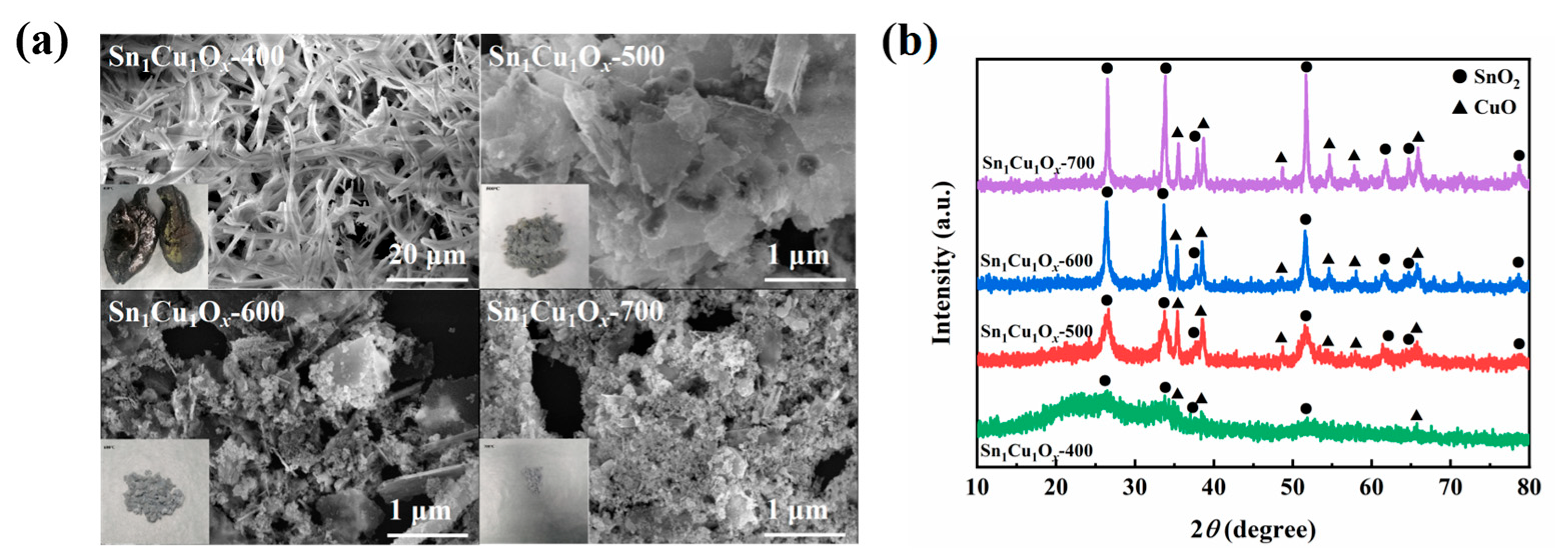
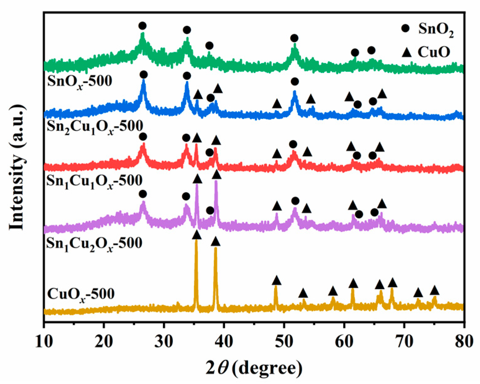
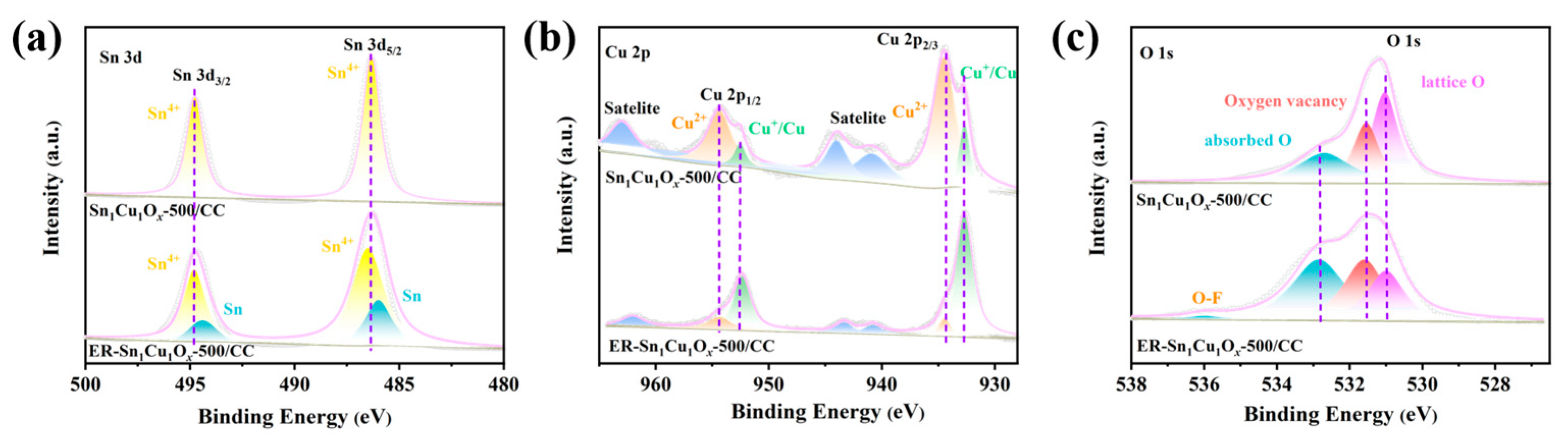
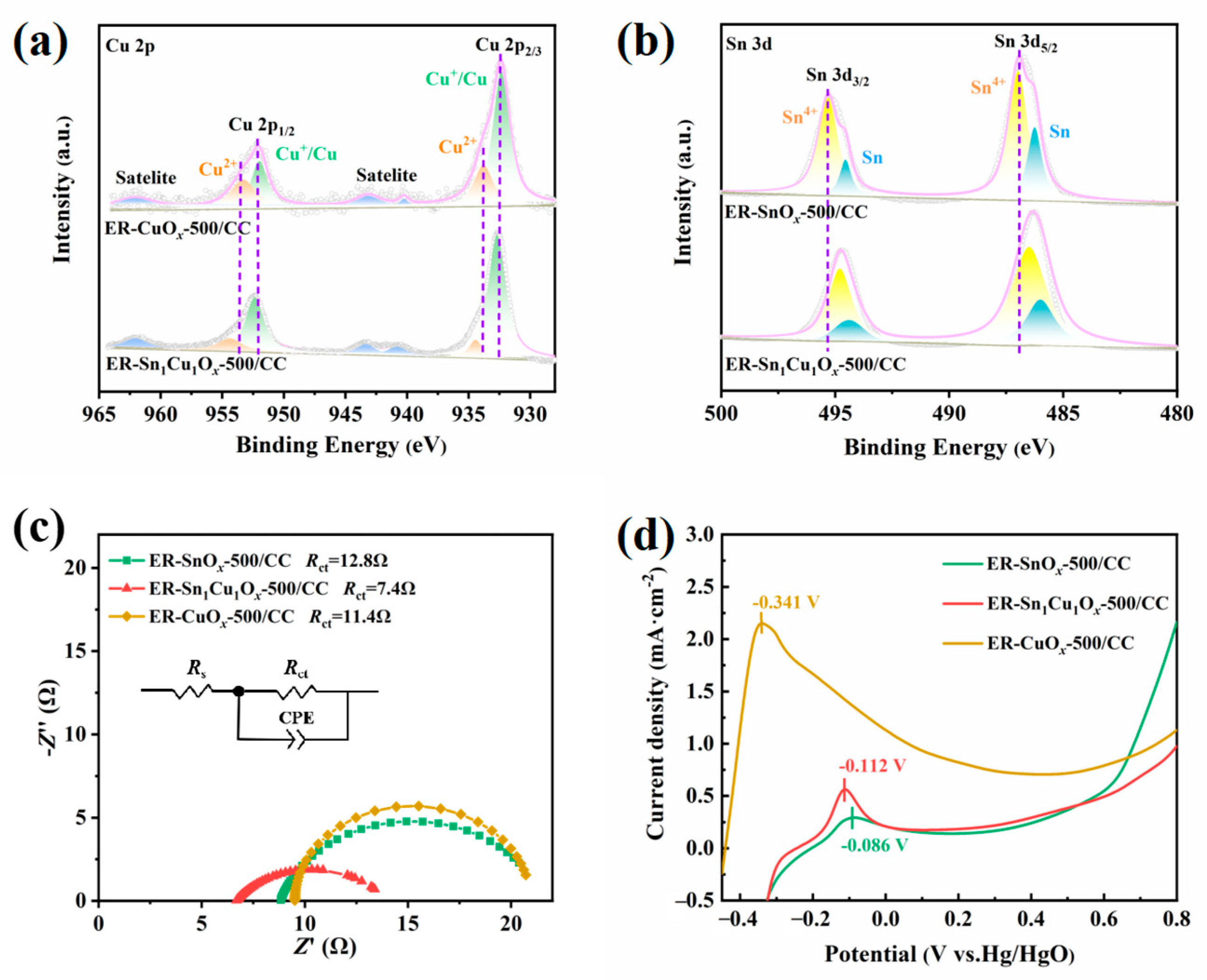
2.1. Synthesis and Characterizations of Catalysts

As schematically illustrated in Figure 1, SnmCunOx-t was first synthesized via a chemical foaming method. Here, m/n was the molar ratio of Sn salt to Cu salt in the foaming solution. Take Sn1Cu1Ox-t as an example, the transparent foaming solution consisted of 0.2 mmol SnCl4, 0.2 mmol CuCl2, 2 g urea, 10 g glucose, and 10 mL water, and was foamed at 140 °C for 12 h. The obtained foam was annealed in a muffle furnace at an appropriate temperature(t) for 12 h to remove the organic template and generate the Sn1Cu1Ox-t powder. Then, Sn1Cu1Ox-t ink was formed by the ultrasonic dispersion of Sn1Cu1Ox-t powder in a mixed solution and uniformly dropped onto the carbon cloth (CC) to fabricate the Sn1Cu1Ox-t/CC electrode. After one hour of electrochemical reduction of the Sn1Cu1Ox/CC electrode, ER-Sn1Cu1Ox-t/CC was obtained and employed as the working electrode for ECO2RR. In this work, the influence of the annealing temperature (t = 400, 500, 600, and 700 °C) and bimetallic ratio (m/n = 1/2, 1/1, and 2/1) on the structure, composition, catalytic activity, and selectivity of ER-SnmCunOx-t/CC was systematically investigated. Monometallic SnOx-t and CuOx-t electrocatalysts were also prepared under identical conditions for comparative analysis.
The annealing temperature significantly influences both the removal efficiency of the foam template and the nanoparticle morphology. Figure 2 presents SEM images and XRD patterns of Sn1Cu1Ox-t. Sn1Cu1Ox-400 had a foamy appearance, and its SEM image also showed a nanosheet structure, indicating incomplete removal of the foam template. Moreover, there was a wide peak around 24°, which belonged to the diffraction peak of amorphous C on the XRD patterns of Sn1Cu1Ox-400, further demonstrating that the template had remnants [43]. And the diffraction peaks from CuO and SnO2 were very weak. As for Sn1Cu1Ox-500, the SEM images revealed that the template almost disappeared, and the nanoparticles presented as a thin film, macroscopically resulting in a fluffy shape. On the XRD pattern of Sn1Cu1Ox-500, the diffraction peaks of CuO and SnO2 could be observed, and the wide peak at 24° disappeared, which was consistent with the SEM results. The peaks at 26.4°, 33.7°, 38.0°, 51.9°, 62.0°, 64.6°, and 78.7° corresponded to the (110), (101), (200), (211), (310), (220), and (321) planes of SnO2 (PDF#02-1340), respectively, and those at 35.4°, 38.7°, 48.7°, 54.4°, 58.0°, and 66.1° were assigned to the (002), (200), (−202), (020), (202), and (022) planes of CuO (PDF#02-1041), indicating that Sn1Cu1Ox-500 was composed of CuO and SnO2. As the annealing temperature increased, the morphology of Sn1Cu1Ox-600 and Sn1Cu1Ox-700 gradually transformed from a thin film to a granular form, and there was a tendency to aggregation. In addition, Sn1Cu1Ox-500 exhibited broader diffraction peaks of CuO and SnO2 than Sn1Cu1Ox-600 and Sn1Cu1Ox-700, implying that Sn1Cu1Ox-500 had a certain amorphous structure.
To investigate the effect of bimetallic ratio (m/n) on product composition, a series of SnmCunOx-500 were synthesized and characterized with XRD. As shown in Figure 3, all XRD patterns of SnmCunOx-500 exhibited diffraction features of SnO2 and CuO. As the Sn/Cu molar ratio m/n changed from 1:2 to 2:1, the relative peak intensities of SnO2 increased and those of CuO decreased, indicating bimetallic ratio had an influence on the content of SnO2 and CuO in SnmCunOx-500.
After the electrochemical reduction, SnmCunOx-t/CC was converted to ER-SnmCunOx-t/CC. Figure 4 shows the XRD pattern and SEM image of ER-Sn1Cu1Ox-500/CC. The two broad peaks at 25.0° and 43.1° were attributed to CC [44]. The diffraction peaks at 30.6°, 32.1°, 44.9°, 62.5°, and 64.6° corresponded to the (200), (101), (211), (112), and (321) planes of metallic Sn (PDF#65-0296), respectively. The peaks at 29.3°, 61.2°, and 77.5° were attributed to the (110), (220), and (222) planes of Cu2O (PDF#03-0892), respectively. And the peaks at 43.2° and 50.9° were assigned to the (111) and (200) planes of Cu (PDF#04-0836), respectively. In addition, there were some diffraction peaks of SnO2 at 26.4°, 33.7°, 38.0°, and 39.3°. The above results revealed that SnO2 was partially reduced to Sn, and CuO was transformed to Cu2O and Cu during the electrochemical reduction process. Consequently, ER-Sn1Cu1Ox-500/CC consisted of SnO2, Cu2O, Sn, and Cu. The SEM image in Figure 4b shows that ER-Sn1Cu1Ox-500 exhibited a distinct morphology compared to Sn1Cu1Ox-500. The appearance became grainy, and the particle size was smaller, which was advantageous for increasing the surface area and exposing the active sites. Additionally, due to the thin-film morphology of Sn1Cu1Ox-500, ER-Sn1Cu1Ox-500 can be uniformly distributed on CC, thereby promoting the mass transport efficiency of CO2 and electrolyte, increasing the electrochemically active surface area to enable efficient CO2 adsorption and reduction, and further enhancing the electrocatalytic performance [45,46,47].
Figure 5 shows the XPS spectra of ER-Sn1Cu1Ox-500/CC and Sn1Cu1Ox-500/CC. The peaks at 494.7 and 486.5 eV were ascribed to Sn4+ 3d3/2 and 3d5/2, while signals at 494.3 and 486.0 eV were attributed to metallic Sn 3d3/2 and 3d5/2 [48]. Figure 5a shows that only Sn4+ existed in Sn1Cu1Ox-500/CC, and ER-Sn1Cu1Ox-500/CC consisted of Sn4+ and metallic Sn, indicating SnO2 was partially transformed into metallic Sn during the electroreduction process. Similarly, as presented in Figure 5b, compared with Sn1Cu1Ox-500/CC, the increase in the peak areas for Cu+/Cu0 (952.3 and 932.5 eV attributed to 2p1/2 and 2p3/2) and the decrease in the peak areas for Cu2+ (954.4 and 934.3 eV attributed to 2p1/2 and 2p3/2) in ER-Sn1Cu1Ox-500/CC indicated a reduction in Cu2+ to Cu+/Cu0 [49]. Additionally, Figure 5c revealed that ER-Sn1Cu1Ox-500/CC had a smaller peak area of lattice O at 531.0 eV than Sn1Cu1Ox-500/CC [50], further illustrating the electroreduction of metal oxides. Notably, the peak at 531.6 eV assigned to oxygen vacancies also became stronger after the electroreduction of Sn1Cu1Ox-500/CC to ER-Sn1Cu1Ox-500/CC, which was believed to benefit the electrocatalytic activity (Sections S1, S2 and Table S1) [51,52,53].

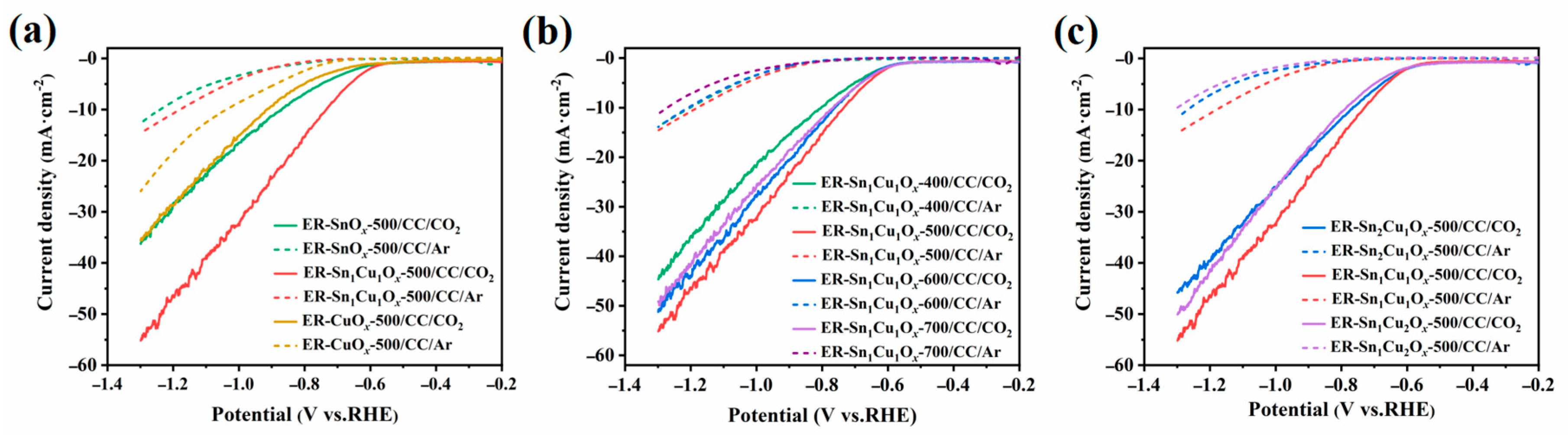
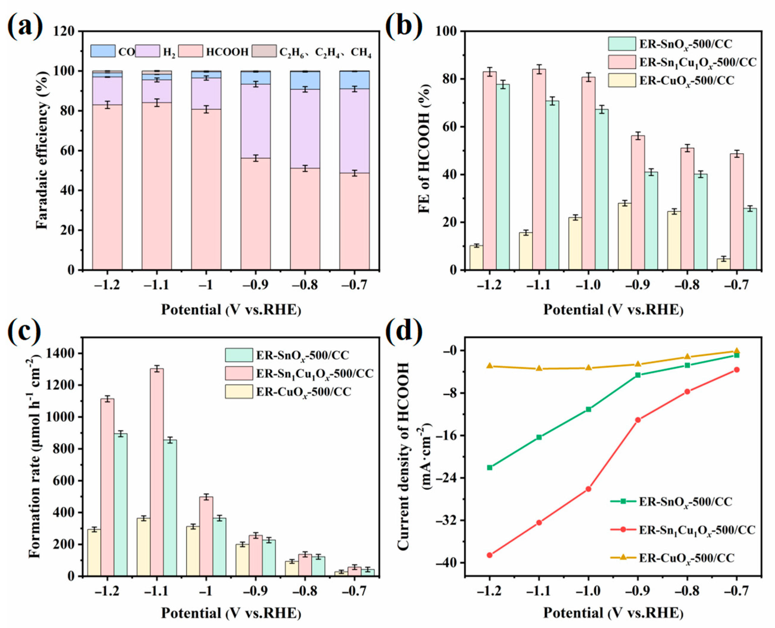
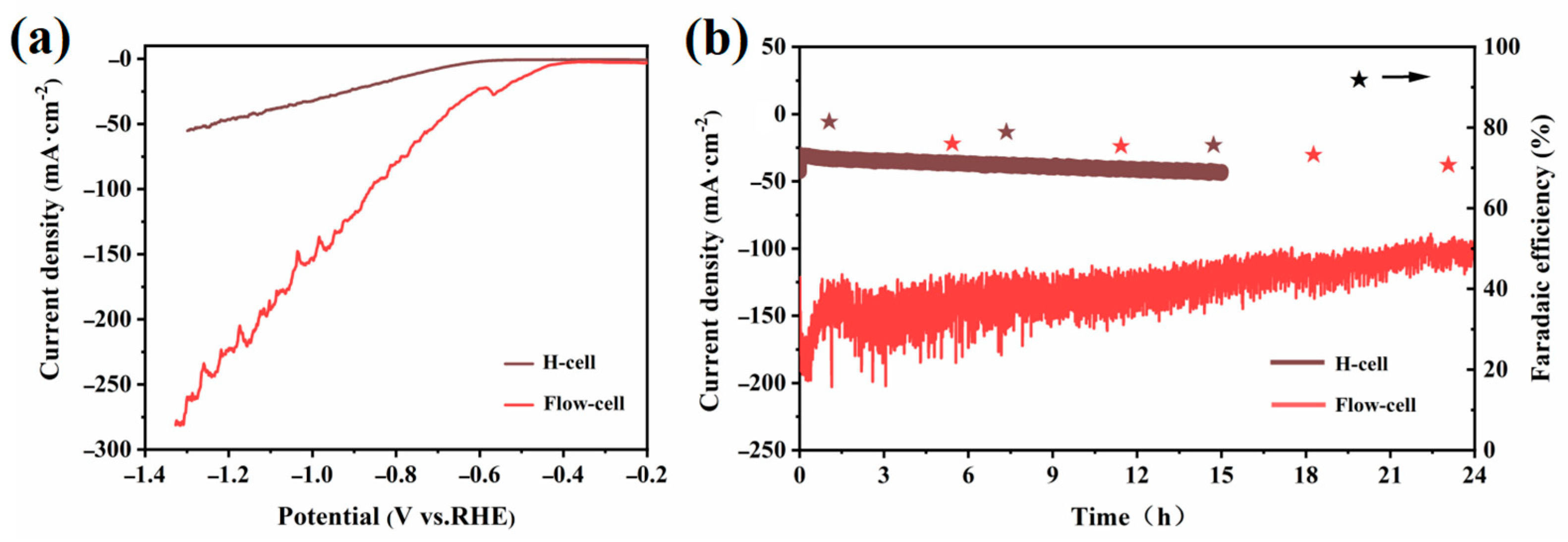
2.2. Electrocatalytic CO2RR Performance of the Catalysts

The electrocatalytic performances of ER-SnmCunOx-t/CC on ECO2RR were investigated in an H-type cell with three electrodes, and the electrolyte was CO2-saturated 0.5 mol·L−1 KHCO3 solution. All the potentials presented here are versus the reversible hydrogen electrode (RHE) unless it was specifically mentioned.
Figure 6a displays the linear scanning voltammetry (LSV) curves of ER-Sn1Cu1Ox-500/CC, ER-SnOx-500/CC, and ER-CuOx-500/CC in CO2 (or Ar)-saturated 0.5 mol·L−1 KHCO3 solution. The onset potentials and the overpotentials at the same current density for the three electrocatalysts in the CO2-saturated solution were lower than those in the Ar-saturated solution, demonstrating that the three electrocatalysts all had an electrocatalytic activity on ECO2RR. And ER-Sn1Cu1Ox-500/CC exhibited the best catalytic performance and achieved a current density of 38.6 mA·cm−2 at −1.1 V vs. RHE, which was about 1.7-fold higher than ER-SnOx-500/CC and ER-CuOx-500/CC.
Evidently, the annealing temperature and bimetallic ratio should play a critical role in their electrocatalytic performance on ECO2RR because they had an effect on the morphology and composition of ER-SnmCunOx-t/CC. Annealing at 500 °C ensures the complete removal of the foam template, avoiding residual amorphous carbon, and generates a hierarchical thin-film structure with optimal crystallinity of CuO and SnO2. This balance between active site exposure and structural stability is unattainable in samples annealed at lower temperatures (incomplete template removal) or higher temperatures (particle agglomeration). A 1:1 Sn/Cu molar ratio facilitates synergistic heterointeractions between SnO2 and CuO phases. Upon electrochemical reduction, these phases yield a multicomponent active layer comprising SnO2, Cu2O, Sn, Cu, and oxygen vacancies. These components enhance CO2 adsorption and intermediate stabilization. As depicted in Figure 6b,c, ER-Sn1Cu1Ox-500/CC presented the optimal electrochemical performance. Therefore, 500 °C and 1/1 were selected as the annealing temperature and bimetallic ratio, respectively, to prepare the electrocatalyst in subsequent experiments.
Differential electrochemical mass spectrometry (DEMS) was used to qualitatively analyze the ECO2RR products of ER-Sn1Cu1Ox-500/CC. As shown in Figure 7, there were four products detected by DEMS: H2 (m/z = 2), CH4 (m/z = 16), CO (m/z = 28), and HCOO- (m/z = 44). Based on these results, the conclusion could be drawn that the liquid-phase product of ECO2RR at ER-Sn1Cu1Ox-500/CC was HCOOH, and the gas-phase products included CO and CH4.
Nuclear magnetic resonance spectroscopy (1H NMR) and gas chromatography (GC) were employed to quantify the product distribution, and Faradaic efficiency (FE) calculated via Equations (3) and (4) was used to evaluate the product selectivity of ER-Sn1Cu1Ox-500/CC. Figure 8a revealed that the products of ECO2RR at ER-Sn1Cu1Ox-500/CC mainly included HCOOH and CO, which matched DEMS results. Figure 8b,c shows that ER-Sn1Cu1Ox-500/CC and ER-SnOx-500/CC exhibit excellent selectivity toward HCOOH, with both FEs and formation rates increasing as the potential becomes more negative. ER-Sn1Cu1Ox-500/CC reaches peak values of 84.1% and 1303 μmol h−1 cm⁻2 at −1.1 V, higher than those of ER-SnOx-500/CC (77.7%, 855 μmol h⁻1 cm⁻2) and ER-CuOx-500/CC (28.0%, 364 μmol h⁻1 cm⁻2). Moreover, as displayed in Figure 8d, partial current densities (JHCOOH) of ER-Sn1Cu1Ox-500/CC were much higher than those of ER-SnOx-500/CC at the same potentials, and at −1.1 V, it was about twice that of ER-SnOx-500/CC. Correspondingly, Figure 8b,c indicates that ER-CuOx-500/CC exhibited low selectivity for HCOOH. These results demonstrated that ER-Sn1Cu1Ox-500/CC not only maintained the high selectivity of ER-SnOx-500/CC for HCOOH but also enhanced the electrocatalytic activity.
To evaluate the practical applicability of ER-Sn1Cu1Ox and solve the restricted solubility of CO2 in aqueous electrolytes, a flow cell reactor was also employed to investigate the electrochemical performance. By employing a gas diffusion electrode (GDE) as the working electrode, gaseous CO2 was directly delivered to the electrode-electrolyte interface, effectively circumventing the limitations of mass transfer and improving the current density. Figure 9a compares the LSV curves of ER-Sn1Cu1Ox-500 in the flow cell and H-type cell. The flow cell enables a significant enhancement in current density, reaching a peak of 280 mA·cm⁻2 at −1.3 V vs. RHE, which shows great catalytic activity and is approximately five times higher than that in the H-type cell (55 mA·cm⁻2).
Stability is a critical performance metric for the practical application of electrocatalysts. As shown in Figure 9b, after 15 h of electrolysis at −1.1 V vs. RHE in the H-type cell, the current density of ER-Sn1Cu1Ox-500 remained undiminished, and the FE for HCOOH stayed above 76.3%. In contrast, the flow cell exhibited equally remarkable durability during a 24-h i-t test, maintaining a current density exceeding 100 mA·cm⁻2 and HCOOH selectivity greater than 70%, which collectively demonstrates excellent electrochemical stability. Additionally, minor carbonate deposition (predominantly potassium carbonate) was observed on the electrode surface after prolonged electrolysis, which is attributed to side reactions between generated OH⁻ and CO2 in the solution [54]. However, the high formic acid selectivity at −1.1 V suppresses competitive reactions such as hydrogen evolution (HER), thereby slowing down the excessive accumulation of alkalinity and reducing the carbonate deposition rate, both of which are beneficial for maintaining the stability of catalytic performance. Collectively, ER-Sn1Cu1Ox-500 exhibited high electrocatalytic activity, favorable selectivity, and superior stability toward ECO2RR, which was comparable or superior to the reported HCOOH-selective electrocatalysts for ECO2RR in Table 1 in terms of Faradaic efficiency and current density.

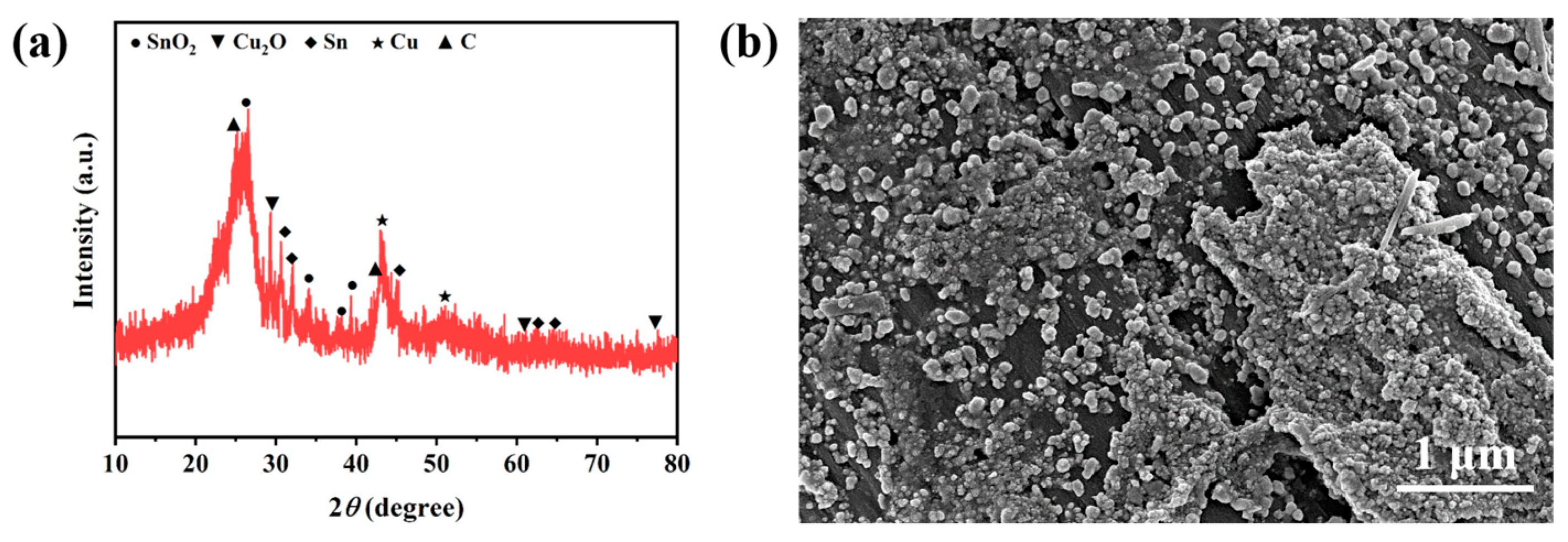
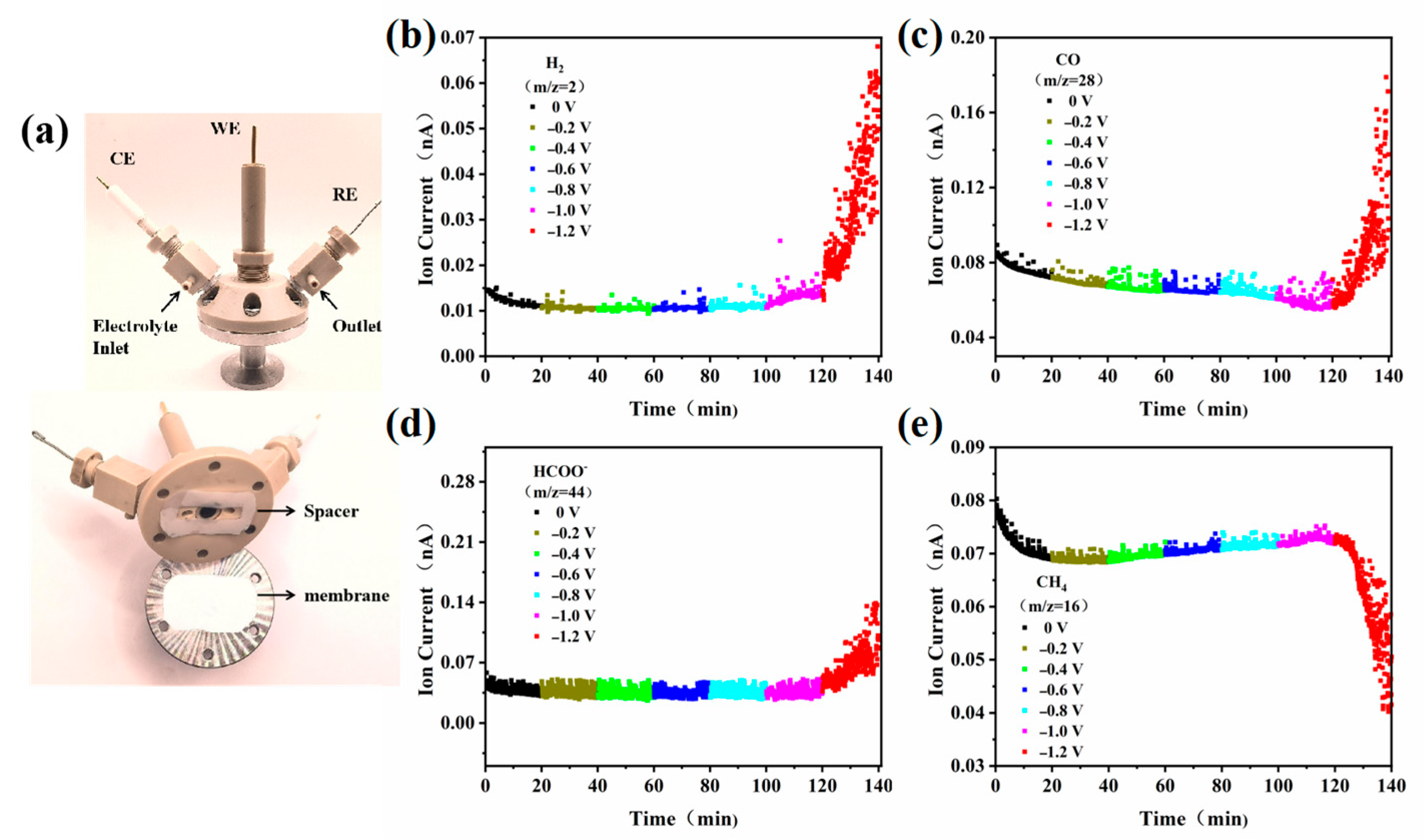
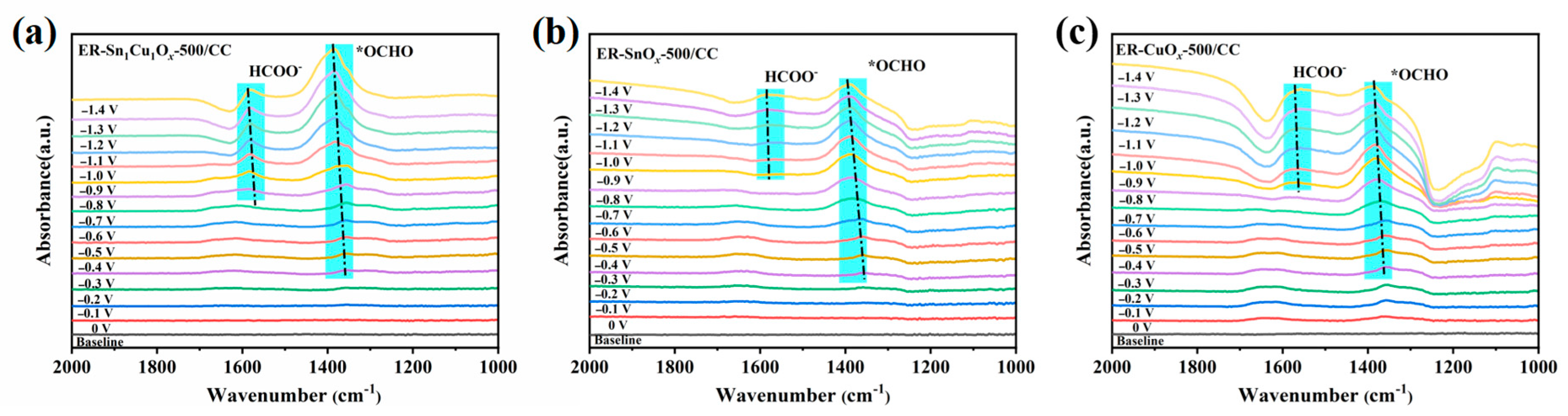
2.3. Electrocatalytic Mechanism Study of ECO2RR

The excellent electrocatalytic performance of ER-Sn1Cu1Ox-500 largely benefited from the combined effect of Cu and Sn.
First, the coexistence of Cu and Sn had an influence on the electronic structure of the catalyst. As shown in Figure 10a,b, compared with ER-SnOx-500 and ER-CuOx-500, the binding energy of Cu 2p from ER-Sn1Cu1Ox-500 exhibits a slight positive shift, while that of Sn 3d shows a slight negative shift. This indicates that the interaction between Cu and Sn induces partial electron transfer from Cu to Sn via an interfacial coupling effect, leading to charge redistribution between the two metals [68].
Secondly, ER-Sn1Cu1Ox-500 possessed a faster charge transfer and appropriate adsorption for the intermediate *CO2 than ER-SnOx-500/CC and ER-CuOx-500/CC, further confirming the interplay between Cu and Sn. Figure 10c shows the Nyquist plots of the three electrodes measured via electrochemical impedance spectroscopy (EIS). Among them, ER-Sn1Cu1Ox-500/CC exhibited the smallest semicircular radius and charge transfer resistance (Rct), demonstrating the fastest ECO2RR kinetics at the electrode/solution interface [69]. The bonding strength between the intermediate *CO2 and the electrocatalyst is considered to have a significant impact on ECO2RR [70]. A too-weak binding strength usually requires a higher overpotential for ECO2RR, making it difficult to proceed, while too-strong binding is not conducive to the desorption of *CO2, hindering the progress of subsequent steps. LSV tests of OH- adsorption in a N2-saturated 1 mol·L−1 KOH solution can serve as an alternative method to evaluate the bonding strength between the intermediate *CO2 and the electrocatalyst [71]. Generally, a more negative potential for OH- adsorption indicates a stronger binding of *CO2 on the electrodes. As shown in Figure 10d, ER-CuOx-500/CC had the most negative potential at −0.341 V, while ER-SnOx-500/CC had the most positive potential at −0.089 V, suggesting the strongest and weakest bonding ability with *CO2, respectively. Meanwhile, ER-Sn1Cu1Ox-500/CC displayed an intermediate bonding ability with *CO2, which allowed the initial step of ECO2RR to proceed at a lower overpotential and facilitated the desorption of *CO2 for the subsequent reaction.
Finally, in situ Fourier transform infrared spectroscopy tests (in situ FTIR) also supported the above results. As shown in Figure 11, the absorption peaks at 1357 cm⁻1 and 1583 cm⁻1, corresponding to key intermediates in the ECO2RR. These peaks can be assigned to the vibrational modes of *OCHO (the critical intermediate for HCOOH production) and HCOO⁻, respectively [72,73]. Although these peaks are detected in the FTIR spectra of all three electrodes, the highest peak intensities are observed for ER-Sn1Cu1Ox-500/CC, indicating its superior ability to stabilize the *OCHO intermediate and promote HCOOH formation.
In summary, the synergistic interaction between Cu and Sn could regulate the electronic structure, promote the charge transfer and the adsorption of *CO2, and stabilize *OCHO, thus enhancing the catalytic activity for ECO2RR and the selectivity for HCOOH.

3. Experiments and Methods

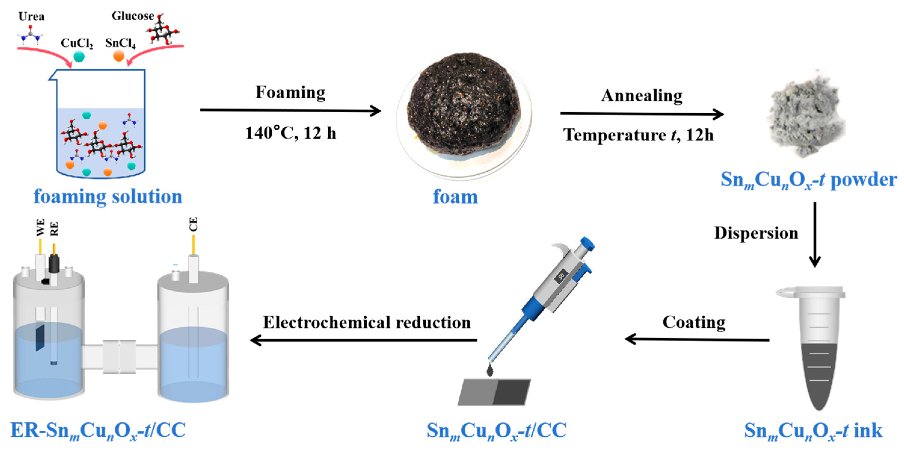
3.1. Preparation of SnmCunOx-t

SnmCunOx-t was synthesized via a chemical foaming method. A total of 2 g urea and 10 g glucose were sequentially dissolved in 10 mL solution containing SnCl4 and CuCl2 with a certain molar ratio (m/n = 1/2, 1/1, and 2/1) to form a homogeneous foaming solution. Here, CuCl2 remained at 0.2 mmol, and SnCl4 was added in the m/n ratio. Then the foaming solution was transferred to a blast oven and heated at 140 °C for 12 h to induce foaming. The resulting foam was annealed in a muffle furnace at an optimized temperature (t = 400, 500, 600, and 700 °C) for 12 h to obtain SnmCunOx-t. Monometallic SnOx-t and CuOx-t were prepared under identical conditions but without CuCl2 or SnCl4, respectively.

3.2. Fabrication of ER-SnmCunOx-t/CC

ER-SnmCunOx-t/CC was fabricated as follows: First, CC (1 cm × 2 cm) was pretreated with ultrasonic cleaning in acetone, ethanol, and deionized water for 5 min each, followed by drying at 30 °C. A catalyst ink was prepared by dispersing 15 mg SnmCunOx-t and 10 μL 5 wt% Nafion solution in a mixture containing 495 μL DMF and 495 μL deionized water via sonication for 30 min. The ink was dropped onto a 1 cm × 1 cm area of pretreated CC and dried at 30 °C to remove solvents. Finally, SnmCunOx-t/CC was electrochemically reduced at −0.8 V vs. RHE for 1 h to generate ER-SnmCunOx-t/CC.

3.3. Characterization

The structure and chemical compositions of the prepared materials were investigated using SEM (Hitachi SU8010, Tokyo, Japan), XRD (Bruker D8 advance, Bremen, Germany), and XPS (Thermo K-alpha, Waltham, MA, USA). The generation of intermediate products and products during ECO2RR with the elevation of potential was monitored using in situ FTIR (PE Spectrum 3, Waltham, MA, USA) with an MCT detector.

3.4. Electrochemical Measurements

The electrochemical experiments for ECO2RR were carried out using an electrochemical workstation (CHI660E, Shanghai, China) at room temperature. The electrolyte was CO2-saturated 0.5 mol·L−1 KHCO3.
For the tests in the H-type cell, Nafion 117 membrane was used to separate the cathode and anode pool. ER-SnmCunOx-t/CC, a Pt column electrode, and a saturated calomel electrode (SCE) were used as the working electrode, counter electrode, and reference electrode, respectively. During the experiment process, CO2 was constantly flowed into the electrolyte solution with 30 mL·min−1 to maintain the saturation state of CO2 in the solution. The recorded potentials relative to SCE (ESCE) in this part of the work were converted to potentials vs. RHE (ERHE) via Equation (1).
ERHE = ESCE + 0.244 V + 0.0591 pH
For the measurements in the flow cell, the gas diffusion electrode (GDE, 0.5 cm × 2 cm) was coated with SnmCunOx-t ink and then reduced at −0.8 V vs. RHE for 1 h to obtain ER-SnmCunOx-t/GDE, which worked as the cathode. A platinum plate (2 cm × 2 cm × 1 mm) and Ag/AgCl electrode (in saturated KCl solution) served as the anode and reference electrode, respectively. The electrolyte solution was pumped into the cell at a flow rate of 10 r·min−1, and the flow rate of CO2 gas into the cathode region was kept at 40 sccm. The obtained potentials relative to the Ag/AgCl electrode (EAg/AgCl) were converted to potentials vs. RHE (ERHE) via Equation (2).
ERHE = EAg/AgCl + 0.21 V + 0.0591 pH

3.5. Product Analysis

The products were analyzed using DEMS (Linglu QMG 220M2, Shanghai, China), gas chromatography (GC, Fuli 9790Plus, Wenling, China), and 1H NMR (Bruker AVANCE III 500MHz, Germany).
For DEMS measurements, the glassy carbon electrode attached with ER-SnmCunOx-t/CC was the working electrode. The platinum wire electrode and Ag/AgCl electrode were the counter electrode and reference electrode, respectively. The i-t test at the various potentials in the range of −0.2~−1.2 V vs. RHE was performed, and at the same time, mass spectra were recorded by a mass spectrometer (Pfeiffer Vacuum QMA 200, Piddinghoe, UK) at 70 eV and 2 mA. Throughout the testing process, the vacuum level was kept at 3–6 × 10⁻⁶ mbar to prevent liquid from entering the mass spectrometer.
FEg(%) of the gas-phase products and FEl (%) could be obtained via Equations (3) and (4), respectively.
FEg = (CgutZF/VmQtotal) × 100%
FEl = (ZFClV/Qtotal) × 100%
Here, Cg is the concentration of gas products detected by GC, and Cl is the concentration of liquid products obtained from 1HNMR. Qtotal is the total charge passed through the circuit. t, u, and Vm present the reaction time, flow rate, and molar volume of CO2, respectively. V is the electrolyte volume in the cathode chamber. Z and F are the number of electrons transferred and Faraday’s constant, respectively.
The formation rate of the product was calculated using Equation (5) as follows:
Formation rate = Qtotal FE/ZFtS
where t is the electrolysis time (h) and S is the geometric area of the electrode (cm2).
Each of the tests described above was performed in triplicate to evaluate performance variability.

4. Conclusions

In summary, a chemical foaming method was employed to prepare SnmCunOx-t with a thin-film structure, and then an electrochemical method was applied to reduce SnmCunOx-t to ER-SnmCunOx-t. The thin-film-like morphology of Sn1Cu1Ox-500 made ER-Sn1Cu1Ox-500 nanoparticles uniformly distributed on CC, and the electroreduction caused the generation of oxygen vacancies in ER-Sn1Cu1Ox-500, which favored the electrocatalytic performance of ER-Sn1Cu1Ox-500 for ECO2RR. Moreover, there was a synergistic interaction between Cu and Sn, which could regulate the electronic structure, promote the charge transfer, and regulate the adsorption of intermediates, resulting in a significant improvement in the catalytic activity for ECO2RR and the selectivity for HCOOH. Under the optimal conditions, ER-Sn1Cu1Ox-500/CC achieved 84.1% FE for HCOOH at −1.1 V vs. RHE, and the corresponding JHCOOH was up to 32.4 mA·cm−2 in the H-type cell. Especially in the flow cell, ER-Sn1Cu1Ox-500/GDE could reach a high JHCOOH of 190 mA·cm−2 at −1.1 V vs. RHE and maintained a JHCOOH higher than 100 mA·cm−2 for 24 h, outperforming most reported HCOOH-selectivity electrocatalysts. This work provides a novel strategy for designing efficient bimetallic catalysts for ECO2RR.

Supplementary Materials

The following supporting information can be downloaded at https://www.mdpi.com/article/10.3390/catal15050484/s1, Section S1: Explanation for demonstrating the presence of oxygen vacancies via XPS; Section S2: The process of determining the oxygen vacancy concentration by XPS; Table S1: The area ratio of oxygen vacancy-related peaks to the total O 1s peak area. Refs. [51,52,53,74,75] are cited in the Supplementary Materials.

Author Contributions

C.Z.: Data curation, Formal analysis, Investigation, Methodology, Validation, Visualization, Writing—original draft, Writing—review and editing. A.Y.: Data curation, Formal analysis, Investigation, Methodology, Validation, Visualization, Writing—original draft, Writing—review and editing. Y.Z.: Data curation, Formal analysis, Investigation, Methodology. W.C.: Investigation, Methodology, Validation, Writing—original draft. Z.W.: Formal analysis, Validation. M.X.: Investigation, Validation. D.Q.: Supervision, Writing—review and editing. J.D.: Conceptualization, Supervision, Writing—review and editing. X.L.: Conceptualization, Funding acquisition, Supervision, Writing—review and editing. All authors have read and agreed to the published version of the manuscript.

Funding

This work was supported by the Fundamental Research Funds for the Central Universities (104972024KFYjc0079) and the National Training Program of Innovation and Entrepreneurship for Undergraduates (S202410497197).

Data Availability Statement

The raw data supporting the conclusions of this article will be made available by the authors upon request.

Acknowledgments

The authors would like to thank SCI-GO (www.sci-go.com (accessed on 14 May 2025)) for XPS and SEM measurements and the Center for Materials Research and Analysis of Wuhan University of Technology for XRD tests.

Conflicts of Interest

The authors declare no conflicts of interest.

References

  1. Houghton, R. Global carbon budgets and the role of remote sensing. Remote Sens. Handb. 2024, 4, 395–422. [Google Scholar]
  2. Xu, H.; Wang, L.; Geng, R.; Li, J.; Zhang, C.; Lu, F. Comparison of international low-carbon and sustainable district evaluation systems and the implications for China. EDP Sci. 2025, 618, 3003. [Google Scholar] [CrossRef]
  3. Zhao, J.; Zhang, P.; Yuan, T.; Cheng, D.; Zhen, S.; Gao, H.; Wang, T.; Zhao, Z.; Gong, J. Modulation of *CHxO adsorption to facilitate electrocatalytic reduction of CO2 to CH4 over Cu-based catalysts. J. Am. Chem. Soc. 2023, 145, 6622–6627. [Google Scholar] [CrossRef]
  4. Jia, G.; Wang, Y.; Sun, M.; Zhang, H.; Li, L.; Shi, Y.; Zhang, L.; Cui, X.; Lo, T.; Huang, B. Size effects of highly dispersed bismuth nanoparticles on electrocatalytic reduction of carbon dioxide to formic acid. J. Am. Chem. Soc. 2023, 145, 14133–14142. [Google Scholar] [CrossRef]
  5. Cao, Y.; Chen, S.; Bo, S.; Fan, W.; Li, J.; Jia, C.; Zhou, Z.; Liu, Q.; Zheng, L.; Zhang, F. Single atom Bi decorated copper alloy enables C−C coupling for electrocatalytic reduction of CO2 into C2+ products. Angew. Chem. Int. Ed. 2023, 62, e202303048. [Google Scholar] [CrossRef]
  6. Ma, Y.; Xu, R.; Wu, X.; Wu, Y.; Zhao, L.; Wang, G.; Li, F.; Shi, Z. Progress in catalysts for formic acid production by electrochemical reduction of carbon dioxide. Top. Curr. Chem. 2025, 383, 2. [Google Scholar] [CrossRef]
  7. Lin, J.; Zhang, N. Constructing strain in electrocatalytic materials for CO2 reduction reactions. Green Chem. 2024, 26, 4449–4467. [Google Scholar] [CrossRef]
  8. Zhou, S.; Guan, Z.; Chen, G.; Wu, J.; Pan, Y.; Guo, Y.; Yang, Z. Advances and strategies in the electrocatalytic conversion of carbon dioxide to valuable chemicals and fuels. Fuel 2024, 377, 132539. [Google Scholar] [CrossRef]
  9. Yu, X. Research and significance of Electroenzymatic conversion of carbon dioxide. Appl. Comput. Eng. 2025, 123, 248–254. [Google Scholar] [CrossRef]
  10. Kong, F.; Chen, W. Carbon dioxide capture and conversion using metal-organic framework (MOF) materials: A comprehensive review. Nanomaterials 2024, 14, 1340. [Google Scholar] [CrossRef]
  11. Sun, Z.; Zhai, Y.; Mei, G.; Guo, W.; Fang, Z.; Jiao, L.; Zhu, Z.; Lu, X.; Tang, J. In situ generated controllable Ag0-Ag+ sites for enhanced eletroreduction of CO2 to CO. Electrochim. Acta. 2023, 470, 143328. [Google Scholar] [CrossRef]
  12. Zhang, H.; Sun, Y.; Wang, J.; Gao, X.; Tang, Z.; Li, S.; Hou, Z.; Wang, X.; Nie, K.; Xie, J. Engineering COBridge adsorption in Cu2O-TiO2 heterojunction catalyst for selective electrochemical CO2 reduction to ethanol. ACS Appl. Energy Mater. 2023, 6, 11448–11457. [Google Scholar] [CrossRef]
  13. Zhang, G.; Qin, X.; Deng, C.; Cai, W.; Jiang, K. Electrocatalytic CO2 and HCOOH interconversion on Pd-based catalysts. Adv. Sens. Energy Mater. 2022, 1, 100007. [Google Scholar] [CrossRef]
  14. Shi, J.; Sun, S.; Liu, J.; Niu, Q.; Dong, L.; Huang, Q.; Liu, J.; Wang, R.; Xin, Z.; Zhang, D. Calixarene-functionalized stable bismuth oxygen clusters for specific CO2-to-HCOOH electroreduction. ACS Catal. 2022, 12, 14436–14444. [Google Scholar] [CrossRef]
  15. Zheng, T.; Liu, C.; Guo, C.; Zhang, M.; Li, X.; Jiang, Q.; Xue, W.; Li, H.; Li, A.; Pao, C. Copper-catalysed exclusive CO2 to pure formic acid conversion via single-atom alloying. Nat. Nanotechnol. 2021, 16, 1386–1393. [Google Scholar] [CrossRef]
  16. Song, M.; Wang, M.; Yuan, Z.; Liu, H.; Zhang, B.; Cui, B.; Chen, B.; Liu, T.; Zhang, X. Efficient electrocatalytic reduction of CO2 to CO by Cu-doped carbon materials derived from ZIF-8. Chem. Select. 2024, 9, e202304917. [Google Scholar] [CrossRef]
  17. Liu, Y.; Zhang, M.; Bao, K.; Huang, H.; Kang, Z. Highly selective conversion of carbon dioxide to methane by copper single atom electrocatalysts. ChemSusChem 2025, 18, e202401314. [Google Scholar] [CrossRef]
  18. Li, M.; Wang, H.; Luo, W.; Sherrell, P.; Chen, J.; Yang, J. Heterogeneous Single-atom catalysts for electrochemical CO2 reduction reaction. Adv. Mater. 2020, 32, 2001848. [Google Scholar] [CrossRef]
  19. Díaz-Sainz, G.; Fernández-Caso, K.; Ávila-Bolívar, B.; Montiel, V.; Solla-Gullón, J.; Alvarez-Guerra, M.; Irabien, A. Advances in the development of innovative Bi-Sn-Sb-based gas diffusion electrodes for continuous CO2 electroreduction to formate. J. CO2 Util. 2025, 95, 103070. [Google Scholar] [CrossRef]
  20. Fernández-Caso, K.; Díaz-Sainz, G.; Álvarez-Guerra, M.; Irabien, A. Electroreduction of CO2: Advances in the continuous production of formic acid and formate. ACS Energy Lett. 2023, 8, 1992–2024. [Google Scholar] [CrossRef]
  21. Ding, P.; Zhao, H.; Li, T.; Luo, Y.; Fan, G.; Chen, G.; Gao, S.; Shi, X.; Lu, S.; Sun, X. Metal-based electrocatalytic conversion of CO2 to formic acid/formate. J. Mater. Chem. A. 2020, 8, 21947–21960. [Google Scholar] [CrossRef]
  22. Peña-Rodríguez, A.; Fernández-Caso, K.; Díaz-Sainz, G.; Álvarez-Guerra, M.; Montiel, V.; Solla-Gullón, J. Single-Pass Electrooxidation of glycerol on bismuth-modified platinum electrodes as an anodic process coupled to the continuous CO2 electroreduction toward formate. ACS Sustain. Chem. Eng. 2024, 12, 3671–3679. [Google Scholar] [CrossRef]
  23. Han, N.; Ding, P.; He, L.; Li, Y.; Li, Y. Promises of main group metal-based nanostructured materials for electrochemical CO2 reduction to formate. Adv. Energy Mater. 2020, 10, 1902338. [Google Scholar] [CrossRef]
  24. Díaz-Sainz, G.; Álvarez-Guerra, M.; Irabien, A. Continuous electrochemical reduction of CO2 to formate: Comparative study of the influence of the electrode configuration with Sn and Bi-based electrocatalysts. Molecules 2020, 25, 4457. [Google Scholar] [CrossRef]
  25. Al-Tamreh, S.A.; Ibrahim, M.H.; El-Naas, M.H.; Vaes, J.; Pant, D.; Benamor, A.; Amhamed, A. Electroreduction of carbon dioxide into formate: A comprehensive review. ChemElectroChem 2021, 8, 3207–3220. [Google Scholar] [CrossRef]
  26. Abarca, J.A.; Abdolhosseini, G.; Sanz, J.M.; Solla-Gullón, J.; Garcés-Pineda, F.A.; Díaz-Sainz, G.; Irabien, A. Coupling Ni-based anodes for textile industry process stream electrooxidation with electrocatalytic CO2 reduction to formate in gas phase. J. CO2 Util. 2025, 93, 103053. [Google Scholar] [CrossRef]
  27. Duarah, P.; Haldar, D.; Yadav, V.; Purkait, M.K. Progress in the electrochemical reduction of CO2 to formic acid: A review on current trends and future prospects. J. Environ. Chem. Eng. 2021, 9, 106394. [Google Scholar] [CrossRef]
  28. Proietto, F.; Patel, U.; Galia, A.; Scialdone, O. Electrochemical conversion of CO2 to formic acid using a Sn based electrode: A critical review on the state-of-the-art technologies and their potential. Electrochim. Acta. 2021, 389, 138753. [Google Scholar] [CrossRef]
  29. Tay, Y.F.; Tan, Z.H.; Lum, Y. Engineering Sn-based catalytic materials for efficient electrochemical CO2 reduction to formate. ChemNanoMat 2021, 7, 380–391. [Google Scholar] [CrossRef]
  30. Shaikh, N.; Shaikh, J.; Márquez, V.; Pathan, S.; Mali, S.; Patil, J.; Hong, C.; Kanjanaboos, P.; Fontaine, O.; Tiwari, A. New perspectives, rational designs, and engineering of Tin (Sn)-based materials for electrochemical CO2 reduction. Mater. Today Sustain. 2023, 22, 100384. [Google Scholar] [CrossRef]
  31. Peterson, A.; Nørskov, J. Activity descriptors for CO2 electroreduction to methane on transition-metal catalysts. J. Phys. Chem. Lett. 2012, 3, 251–258. [Google Scholar] [CrossRef]
  32. Tang, S.; Lu, X.; Zhang, C.; Wei, Z.; Si, R.; Lu, T. Decorating graphdiyne on ultrathin bismuth subcarbonate nanosheets to promote CO2 electroreduction to formate. Sci. Bull. 2021, 66, 1533–1541. [Google Scholar] [CrossRef] [PubMed]
  33. Li, Z.; Cao, A.; Zheng, Q.; Fu, Y.; Wang, T.; Arul, K.; Chen, J.; Yang, B.; Adli, N.; Lei, L.; et al. Elucidation of the synergistic effect of dopants and vacancies on promoted selectivity for CO2 electroreduction to formate. Adv. Mater. 2021, 33, 2005113. [Google Scholar] [CrossRef] [PubMed]
  34. Wang, P.; Yang, H.; Xu, Y.; Huang, X.; Wang, J.; Zhong, M.; Cheng, T.; Shao, Q. Synergized Cu/Pb core/shell electrocatalyst for high-efficiency CO2 reduction to C2+ liquids. ACS Nano 2020, 15, 1039–1047. [Google Scholar] [CrossRef]
  35. Hu, X.; Yang, H.; Guo, M.; Gao, M.; Zhang, E.; Tian, H.; Liang, Z.; Liu, X. Synthesis and characterization of (Cu, S) Co-doped SnO2 for electrocatalytic reduction of CO2 to formate at low overpotential. ChemElectroChem 2018, 5, 1330–1335. [Google Scholar] [CrossRef]
  36. Rabiee, H.; Zhang, X.; Ge, L.; Hu, S.; Li, M.; Smart, S.; Zhu, Z.; Yuan, Z. Tuning the product selectivity of the Cu hollow fiber gas diffusion electrode for efficient CO2 reduction to formate by controlled surface Sn electrodeposition. ACS Appl. Mater. Interfaces 2020, 12, 21670–21681. [Google Scholar] [CrossRef]
  37. Li, D.; Huang, L.; Tian, Y.; Liu, T.; Zhen, L.; Feng, Y. Facile synthesis of porous Cu-Sn alloy electrode with prior selectivity of formate in a wide potential range for CO2 electrochemical reduction. Appl. Catal. B Environ. 2021, 292, 120119. [Google Scholar] [CrossRef]
  38. Wang, M.; Yang, J.; You, X.; Yan, J.; Ding, Y.; Zhang, X.; Dong, S. Electron fixation of Sn2+/Cu+ bimetallic catalyst on flexible carbon fiber cloth for highly converting gaseous CO2 to formate at moderate potential. Int. J. Hydrogen Energy 2022, 47, 2114–2123. [Google Scholar] [CrossRef]
  39. Wang, H.; Maiyalagan, T.; Wang, X. Review on recent progress in nitrogen-doped graphene: Synthesis, characterization, and its potential applications. ACS Catal. 2012, 2, 781–794. [Google Scholar] [CrossRef]
  40. Go, S.; Kwon, W.S.; Hong, D.; Lee, T.; Oh, S.; Bae, D.; Kim, J.; Lim, S.; Joo, Y.; Nam, D. Thermodynamic Phase Control of Cu-Sn Alloy Electrocatalysts for Selective CO₂ Reduction. Nanoscale Horiz. 2024, 9, 2295–2305. [Google Scholar]
  41. Stojkov, S.; El-Nagar, G.A.; Firschke, F.; Pardo Pérez, L.; Choubrac, L.; Najdoski, M.; Mayer, M. Electrocatalyst derived from waste Cu-Sn bronze for CO₂ conversion into CO. ACS Appl. Mater. Interfaces 2021, 13, 38161–38169. [Google Scholar] [CrossRef] [PubMed]
  42. Zhou, C.; Zhao, S.; Meng, H.; Han, Y.; Jiang, Q.; Wang, B.; Shi, X.; Zhang, W.; Zhang, L.; Zhang, R. RuCoOx nanofoam as a high-performance trifunctional electrocatalyst for rechargeable zinc-air batteries and water splitting. Nano Lett. 2021, 21, 9633–9641. [Google Scholar] [CrossRef] [PubMed]
  43. Nie, R.; Wang, J.; Wang, L.; Qin, Y.; Chen, P.; Hou, Z. Platinum supported on reduced graphene oxide as a catalyst for hydrogenation of nitroarenes. Carbon 2012, 50, 586–596. [Google Scholar] [CrossRef]
  44. Jiang, H.; Yang, L.; Deng, W.; Tan, Y.; Xie, Q. Macroporous graphitic carbon foam decorated with polydopamine as a high-performance anode for microbial fuel cell. J. Power Sources 2017, 363, 27–33. [Google Scholar] [CrossRef]
  45. Yang, W.; Qian, L.; Zheng, R.; Yang, D.; Lu, X. Elucidating mass transport within nanoporous Au for CO₂ electroreduction. Catalysts 2023, 13, 883. [Google Scholar] [CrossRef]
  46. Chan, T.; Kong, C.; King, A.; Babbe, F.; Prabhakar, R.; Kubiak, C.; Ager, J. Role of mass transport in electrochemical CO2 reduction to methanol using immobilized cobalt phthalocyanine. ACS Appl. Energy Mater. 2024, 7, 3091–3098. [Google Scholar] [CrossRef]
  47. Qi, Z.; Hawks, S.; Horwood, C.; Biener, J.; Biener, M. Mitigating mass transport limitations: Hierarchical nanoporous gold flow-through electrodes for electrochemical CO2 reduction. Mater. Adv. 2022, 3, 381–388. [Google Scholar] [CrossRef]
  48. Dong, X.; Sun, X.; Jia, S.; Han, S.; Yao, T.; Zhou, D.; Xie, Y.; Xia, W.; Wu, H.; Han, B. In situ formation of Cu-Sn bimetallic catalysts for CO2 electroreduction to formate with high efficiency. Catal. Sci. Technol. 2023, 13, 2303–2307. [Google Scholar] [CrossRef]
  49. Jiang, X.; Li, X.; Kong, Y.; Deng, C.; Li, X.; Hu, Q.; Yang, H.; He, C. Oxidation State Modulation of bimetallic tin-copper oxide nanotubes for selective CO2 electroreduction to formate. Small 2022, 18, 2204148. [Google Scholar] [CrossRef]
  50. Zhuang, G.; Chen, Y.; Zhuang, Z.; Yu, Y.; Yu, J. Oxygen vacancies in metal oxides: Recent progress towards advanced catalyst design. Sci. China Mater. 2020, 63, 2089–2118. [Google Scholar] [CrossRef]
  51. Han, H.; Jin, S.; Park, S.; Kim, Y.; Jang, D.; Seo, M.H.; Kim, W. Plasma-induced oxygen vacancies in amorphous MnOx boost catalytic performance for electrochemical CO2 reduction. Nano Energy 2021, 79, 105492. [Google Scholar] [CrossRef]
  52. Lakhi, K.; Park, D.; Al-Bahily, K.; Cha, W.; Viswanathan, B.; Choy, J.; Vinu, A. Mesoporous carbon nitrides: Synthesis, functionalization, and applications. Chem. Soc. Rev. 2017, 46, 72–101. [Google Scholar] [CrossRef] [PubMed]
  53. Wang, J.; Sun, M.; Xu, H.; Hao, F.; Wa, Q.; Su, J.; Zhou, J.; Wang, Y.; Yu, J.; Zhang, P. Coordination environment engineering of metal centers in coordination polymers for selective carbon dioxide electroreduction toward multicarbon products. ACS Nano 2024, 18, 7192–7203. [Google Scholar] [CrossRef] [PubMed]
  54. Chen, C.; Li, Y.; Yang, P. Addressing the “alkalinity problem” in CO₂ electrolysis with catalyst design and translation. Joule 2021, 5, 737–742. [Google Scholar] [CrossRef]
  55. Choi, S.; Kwon, T.; Lee, Y. Tailoring the product selectivity of electrochemical CO2 reduction at copper-tin composite oxide nanofibers. J. Alloys Comp. 2025, 1013, 178574. [Google Scholar] [CrossRef]
  56. Kawabe, Y.; Ito, Y.; Hori, Y.; Kukunuri, S.; Shiokawa, F.; Nishiuchi, T.; Jeong, S.; Katagiri, K.; Xi, Z.; Li, Z.; et al. 1T/1H-SnS2 sheets for electrochemical CO2 reduction to formate. ACS Nano. 2023, 17, 11318–11326. [Google Scholar] [CrossRef]
  57. Wang, Y.; Cheng, L.; Zhu, Y.; Liu, J.; Xiao, C.; Chen, R.; Zhang, L.; Li, Y.; Li, C. Tunable selectivity on copper-bismuth bimetallic aerogels for electrochemical CO2 reduction. Appl. Catal. B Environ. 2022, 317, 121650. [Google Scholar] [CrossRef]
  58. Zhao, Z.; Yue, Y.; Wu, S.; Li, Z.; Huang, Q. Synchronous introduction of S into Cu3BiS3 bi-active sites catalyst for synergistic electrocatalysis towards the conversion of CO2 into HCOOH. Surf. Interfaces 2025, 56, 105538. [Google Scholar] [CrossRef]
  59. Cheng, X.; Wu, M.; Xu, Y.; Wang, S.; Wang, D.; Wang, W.; Mitsuzaki, N.; Chen, Z. Electrodeposition of CuxBi1-x-MOF for electrochemical reduction of CO2. J. Solid State Chem. 2024, 338, 124804. [Google Scholar] [CrossRef]
  60. Huo, S.; Weng, Z.; Wu, Z.; Zhong, Y.; Wu, Y.; Fang, J.; Wang, H. Coupled metal/oxide catalysts with tunable product selectivity for electrocatalytic CO₂ reduction. ACS Appl. Mater. Interfaces 2017, 9, 28519–28526. [Google Scholar] [CrossRef]
  61. Wang, J.; Ji, Y.; Shao, Q.; Yin, R.; Guo, J.; Li, Y.; Huang, X. Phase and structure modulating of bimetallic CuSn nanowires boosts electrocatalytic conversion of CO₂. Nano Energy 2019, 59, 138–145. [Google Scholar] [CrossRef]
  62. Tan, S.; Xiong, Z.; Xu, Z.; Zhang, J.; Zhao, Y. Pd-doped tin oxide nanostructured catalysts for electrochemical reduction of carbon dioxide. Electrocatalysis 2025, 16, 153–161. [Google Scholar] [CrossRef]
  63. Lim, J.; Garcia-Esparza, A.; Lee, J.; Kang, G.; Shin, S.; Jeon, S.; Lee, H. Electrodeposited Sn-Cu@Sn dendrites for selective electrochemical CO2 reduction to formic acid. Nanoscale 2022, 14, 9297–9303. [Google Scholar] [CrossRef]
  64. Wang, Z.; Li, Z.; Liu, S.; Hou, L.; Wei, X.; Liu, X.; Qin, Q. Enhancing the selectivity of CO2-to-HCOOH conversion by constructing tensile-strained Cu catalyst. Mater. Today Phys. 2023, 38, 101247. [Google Scholar] [CrossRef]
  65. Feng, H.; Chen, C.; Wang, S.; Zhang, M.; Ding, H.; Liang, Y.; Zhang, X. Theoretical investigation of Cu-Au alloy for carbon dioxide electroreduction: Cu/Au ratio determining C1/C2 selectivity. J. Phys. Chem. Lett. 2022, 13, 8002–8009. [Google Scholar] [CrossRef]
  66. Lim, J.; Kang, P.; Jeon, S.; Lee, H. Electrochemically deposited Sn catalysts with dense tips on a gas diffusion electrode for electrochemical CO₂ reduction. J. Mater. Chem. A. 2020, 8, 9032–9038. [Google Scholar] [CrossRef]
  67. Li, D.; Xie, S.W.; Liang, J.B.; Ma, B.Z.; Fu, J.N.; Wu, J.; Feng, Y.J.; Feng, Z.M. Structure regulated CuSn alloy catalyst for selective electrochemical CO₂-to-formate conversion at higher current densities. Sep. Purif. Technol. 2024, 340, 126545. [Google Scholar] [CrossRef]
  68. Ren, B.; Shao, J.; Li, H.; Xu, Q. Copper-tin bimetallic aerogel alloy for the electroreduction of CO2 to formate. New J. Chem. 2025, 49, 2201–2208. [Google Scholar] [CrossRef]
  69. Kempasiddaiah, M.; Samanta, R.; Panigrahy, S.; Barman, S. Interface-rich highly oxophilic copper/tin-oxide nanocomposite on reduced graphene oxide for efficient electroreduction of CO2 to formate. ACS Appl. Energy Mater. 2023, 6, 3020–3031. [Google Scholar] [CrossRef]
  70. Ning, B.; Liu, M.; Hu, Y.; Jiang, H.; Li, C. Defect engineered SnO2 nanoparticles enable strong CO2 chemisorption toward efficient electroconversion to formate. Dalton Trans. 2022, 51, 3512–3519. [Google Scholar] [CrossRef]
  71. Zhang, B.; Chen, S.; Wulan, B.; Zhang, J. Surface modification of SnO2 nanosheets via ultrathin N-doped carbon layers for improving CO2 electrocatalytic reduction. Chem. Eng. J. 2021, 421, 130003. [Google Scholar] [CrossRef]
  72. Jiang, Y.; Shan, J.; Wang, P.; Huang, L.; Zheng, Y.; Qiao, S.-Z. Stabilizing oxidation state of SnO2 for highly selective CO2 electroreduction to formate at large current densities. ACS Catal. 2023, 13, 3101–3108. [Google Scholar] [CrossRef]
  73. Tu, X.; Liu, X.; Zhang, Y.; Zhu, J.; Jiang, H. Advances in Sn-based oxide catalysts for the electroreduction of CO2 to formate. Green Carbon 2024, 2, 131–148. [Google Scholar] [CrossRef]
  74. Aragón, F.H.; Gonzalez, I.; Coaquira, J.; Hidalgo, P.; Brito, H.; Ardisson, J.; Macedo, W.; Morais, P. Structural and surface study of praseodymium-doped SnO2 nanoparticles prepared by the polymeric precursor method. J. Nanoparticle Res. 2016, 18, 318. [Google Scholar] [CrossRef]
  75. Liang, L.; Niu, K.; Zhang, L.; Tian, J.; Zhou, K.; Wang, X.; Zhang, X.; Hong, M. Engineering oxygen vacancies in mesocrystalline CuO nanosheets for water oxidation. ACS Appl. Nano Mater. 2021, 4, 6135–6144. [Google Scholar] [CrossRef]
Figure 1. Schematic diagram of the ER-SnmCunOx-t/CC electrode preparation.
Catalysts 15 00484 g001
Figure 2. (a) SEM images (inserts were the corresponding optical photographs) and (b) XRD patterns of Sn1Cu1Ox-t.
Catalysts 15 00484 g002
Figure 3. XRD patterns of SnmCunOx-500.
Catalysts 15 00484 g003
Figure 4. (a) XRD pattern and (b) SEM image of ER-Sn1Cu1Ox-500/CC.
Catalysts 15 00484 g004
Figure 5. XPS spectra of ER-Sn1Cu1Ox-500/CC and Sn1Cu1Ox-500/CC: (a) Sn 3d, (b) Cu 2p, and (c) O 1s.
Catalysts 15 00484 g005
Figure 6. LSV curves of (a) ER-Sn1Cu1Ox-500/CC, ER-SnOx-500/CC, and ER-CuOx-500/CC, (b) ER-Sn1Cu1Ox-t/CC, and (c) ER-SnmCunOx-500/CC in CO2 (or Ar)-saturated 0.5 mol·L−1 KHCO3 solution.
Catalysts 15 00484 g006
Figure 7. (a) The electrolytic cell used for DEMS measurements, and the obtained current signals at ER-Sn1Cu1Ox-500/CC: (b) H2, (c) CO, (d) HCOO, (e) CH4.
Catalysts 15 00484 g007
Figure 8. (a) Product FEs of ER-Sn1Cu1Ox-500/CC, (b) FEs, (c) formation rates, and current densities (d) for HCOOH of ER-Sn1Cu1Ox-500/CC, ER-SnOx-500/CC, and ER-CuOx-500/CC at different potentials.
Catalysts 15 00484 g008
Figure 9. (a) LSV curves and (b) stability tests of ER-Sn1Cu1Ox-500 in the flow cell and H-type cell.
Catalysts 15 00484 g009
Figure 10. XPS spectra of (a) Cu 2p of ER-Sn1Cu1Ox-500/CC and ER-CuOx-500/CC and (b) Sn 3d of ER-Sn1Cu1Ox-500/CC and ER-SnOx-500/CC; (c) Nyquist plots in CO2-saturated 0.5 mol·L−1 KHCO3 solution; and (d) LSV curves in 0.1 mol·L−1 KOH solution at ER-Sn1Cu1Ox-500/CC, ER-SnOx-500/CC, and ER-CuOx-500/CC.
Catalysts 15 00484 g010
Figure 11. In situ ATR-FTIR spectra of (a) ER-Sn1Cu1Ox-500/CC, (b) ER-SnOx-500/CC, and (c) ER-CuOx-500/CC.
Catalysts 15 00484 g011
Table 1. Summary of metal catalysts for the reduction of carbon dioxide to HCOOH.
CatalystCellElectrolyteMain
Product
FE
(%)
Current Density at Controlled
Potential
(mA·cm−2)
Controlled
Potential
(V vs. RHE)
Ref.
CuSn2OyH-cell0.1 mol·L−1 KHCO3HCOOH90.03.0−1.1[55]
1T/1H-SnS2H-cell0.1 mol·L−1 KHCO3HCOOH63.311.0−1.31[56]
Cu1Sn3-CCH-cell0.5 mol·L−1 KHCO3HCOOH91.413.79−0.8[57]
Cu3BiS3H-cell0.5 mol·L−1 KHCO3HCOOH88.825.48−0.99[58]
Cux/Bi1-x-BTCH-cell0.1 mol·L−1 KHCO3HCOOH73.414.4−1.5[59]
CuOy/SnOx-CNTH-cell0.1 mol·L−1 KHCO3HCOOH79.06.2−1.1[60]
CuSn NWs/C-AirH-cell0.5 mol·L−1 KHCO3HCOOH87.021.8−1.1[61]
ER-Sn1Cu1OxH-cell0.5 mol·L−1 KHCO3HCOOH84.132.4−1.1This work
0.5 Pd/SnO2Flow cell1 mol·L−1 KOHHCOOH63.090.59−1.2[62]
Sn-Cu@Sn Flow cell1.0 mol·L−1 KHCO3HCOOH84.230.0−0.68[63]
In2O3/CuFlow cell0.5 mol·L−1 KHCO3HCOOH87.570.0−1.4[64]
PEI–Sn/Cu foamFlow cell0.5 mol·L−1 KHCO3HCOOH92.357.1−0.97[65]
SnDTFlow cell1.0 mol·L−1 KHCO3HCOOH62.518.7−0.76[66]
CuSn4Flow cell0.5 mol·L−1 KHCO3HCOOH69.061.0−1.1[67]
ER-Sn1Cu1OxFlow cell0.5 mol·L−1 KHCO3HCOOH70.0192.5−1.1This work
Disclaimer/Publisher’s Note: The statements, opinions and data contained in all publications are solely those of the individual author(s) and contributor(s) and not of MDPI and/or the editor(s). MDPI and/or the editor(s) disclaim responsibility for any injury to people or property resulting from any ideas, methods, instructions or products referred to in the content.

