Article

A Ternary Spinel Strategy for Increasing the Performances of Oxygen Reduction Reaction and Anion Exchange Membrane Fuel Cell Based on Mn-Co Spinel Oxides

School of Energy and Power Engineering, Nanjing University of Science and Technology, 200 Xiaolingwei Street, Nanjing 210094, China
*
Author to whom correspondence should be addressed.
Catalysts 2025, 15(11), 1031; https://doi.org/10.3390/catal15111031 (registering DOI)
Submission received: 29 September 2025 / Revised: 23 October 2025 / Accepted: 25 October 2025 / Published: 1 November 2025
(This article belongs to the Special Issue Metal Oxide-Supported Catalysts)

Abstract

Anion exchange membrane fuel cells (AEMFCs) represent a promising class of clean energy devices, with their performance being critically dependent on the efficiency of the cathode oxygen reduction reaction (ORR) catalyst. Manganese-cobalt spinel (Mn1.5Co1.5O4, MCS) has been demonstrated to be a highly active ORR catalyst. Herein, we report a strategy of incorporating Cu (MCCS) and Fe (MCFS) into MCS to form ternary spinel oxides for tuning ORR activity. Among them, MCS exhibits the best ORR performance, with a half-wave potential (E1/2) of 0.736 V vs. RHE in 0.1 M KOH and a peak power density (PPD) of 248.3 mW·cm−2 for the fuel cell test. In contrast, MCCS and MCFS show divergent behaviors in a rotating disk-ring electrode (RRDE) and fuel cell tests. X-ray diffraction (XRD) analyses and X-ray photoelectron spectroscopy (XPS) analyses reveal that the introduction of Cu2+ and Fe3+ induces a phase transformation in the spinel structure, leading to a reduction in oxygen vacancies and an increase in the valence state of Mn, thereby degrading catalytic activity. However, the incorporation of these elements also modulates the hydration capability of the catalysts, which is critical for the ion and charge transfer in the fuel cell environment and has been validated in the distribution of relaxation time (DRT) analysis of the fuel cell test. This study provides a valuable strategy for designing and synthesizing low-cost, highly efficient, and stable ternary spinel electrocatalysts for AEMFC applications, and bridges the gap between RRDE evaluation and fuel cell testing through DRT analysis.

Graphical Abstract

1. Introduction

Hydrogen fuel cells have been recognized as a critical renewable energy technology, especially for powering electric vehicles, portable electronic devices, and stationary applications [1,2,3]. However, the sluggish kinetics of the oxygen reduction reaction (ORR) at the cathode remains as one of the key challenges [4,5]. To date, Pt-based and Pd-based electrocatalysts are still considered as the most effective commercial candidates for ORR in acidic media, but their high cost and scarcity hinder the widespread and large-scale application of polymer electrolyte membrane fuel cells (PEMFCs) [6,7]. Alternatively, anion exchange membrane fuel cells (AEMFCs) have attracted tremendous attention because they enable the use of nonprecious metal electrocatalysts, which exhibit an improved stability in alkaline media compared to acidic electrolytes [8,9]. To facilitate the ORR kinetics in alkaline media, research efforts have been devoted to searching for cost-effective electrocatalysts, including metal-containing nitrogen-doped carbons (M–N–C) [10,11,12], transition metal oxides (TMOs) [13,14], transition metal nitrides [15], and non-metal catalysts [16,17]. Among them, transition metal oxides such as perovskite and spinel have received much attention due to their tunable d-orbital filling, flexible composition, and abundant reserves, and, most importantly, their good catalytic activity close to noble metal catalysts under alkaline conditions [18,19]. Particularly, spinel metal oxides have been demonstrated to be auspicious ORR electrocatalysts [20].
Spinel-type composite oxides (AB2O4) are typically composed of a tetrahedral coordinated A-site and octahedral coordinated B-site. In AB2O4, different metal ions occupy the A and B sites, and, due to their different valence states and radii, they have different inclinations in the gaps between the oxygen tetrahedra and oxygen octahedra, resulting in a structural transformation of spinel [21]. Meanwhile, the presence of a large number of void positions makes the crystal structure very open and favors the migration of cations [22]. The charge transfer between cations in different valencies through a leap process requires relatively low activation energy, so the inherent multivalency of spinel oxides can significantly improve the electrical conductivity and catalytic activity. In the case of spinel, numerous strategies have been attempted in order to optimize the reactivity and stability of catalysts for the ORR. Recently, spinel oxides containing Mn and Co cations have been proven to be excellent ORR electrocatalysts [23]. Chen et al. [24] reported a simple and rapid method for preparing MxMn3-xO4 (M = divalent metals) spinel nanocrystals at room temperature. The results showed that this method increased the specific surface area of the catalyst from 7 cm2·g−1 to 122 cm2·g−1 compared to traditional solid-phase synthesis, and obtained a half-wave potential (E1/2) of 0.77 V vs. RHE (Reversible Hydrogen Electrode). In addition, Chen et al. [25] proposed a general synthesis of ultrasmall cobalt manganese spinel with tailored structural symmetry and composition through a facile solution-based oxidation–precipitation and insertion–crystallization process at modest condition. This method successfully prepared six CoxMn3-xO4 spinel samples with an active phase selection. Among them, the ORR performance of cubic CoMn2O4 spinel was the best with an E1/2 of 0.73 V vs. RHE, and the oxygen evolution reaction (OER) performance was also relatively excellent. Due to the superior bifunctional oxygen catalytic performance of the CoMn2O4 catalyst, the average potential of the assembled Zn-air battery decreased by only 8.5% after 155 cycles of charge and discharge, which was only half of Pt/C (17.6%), and the voltage platform was more stable. Wang et al. [14] further investigated the catalytic synergy mechanism and membrane electrode assembly (MEA) performance of cobalt manganese spinel. They found Mn-Co spinel exhibits activity that is inferior to that of Pt for ORR in RDE tests, but superior performance in AEMFC tests, in particular under low-humidity conditions. In rotating disk electrode (RDE) tests, the E1/2 for Mn1.5Co1.5O4 was about 0.85 V vs. RHE, which was about 50 mV lower than the typical E1/2 of Pt/C (0.90 V vs. RHE), indicating that the performance of Mn-Co spinel in MEA was lower than that of Pt/C. However, under 100% relative humidity, 60 °C, and H2-O2 mode, the power density of Mn1.5Co1.5O4 was 1.1 W·cm−2, which was better than the 1.0 W·cm−2 of Pt/C. In reality, at a lower relative humidity (50%), Mn1.5Co1.5O4 could still maintain a high level of power density of 0.92 W·cm−2, while the power density of Pt/C dropped sharply to 0.7 W·cm−2. Through comprehensive characterizations, a synergistic effect of the Mn-Co spinel surface was unraveled, where the Mn sites preferred O2 binding and the Co sites favored H2O activation. Such a mechanism was pivotal in the AEMFC cathode, where water was a reactant but usually depleted. This indicated that, in the early catalyst development and screening process, in addition to RDE testing, MEA testing was also necessary. Tang et al. [26] designed a three-dimensional porous spinel NiCo2O4 that allows electrons, ions, and oxygen to pass through continuously, enhancing the electrochemical performance by promoting O2 mass transfer. In RDE testing, the E1/2 of NiCo2O4 was 0.79 V vs. RHE, which was close to Pt/C. At the same time, it also had OER performance, with an overpotential of approximately 390 mV at a current of 10 mA·cm−2.
Moreover, due to the similar radius between Fe ion and Ni/Co ions, Liu et al. [27] doped NiCo2O4 with Fe. Fe preferentially enters the tetrahedral sites, which induced a high proportion of Ni3+ and Co2+ at the octahedral sites, acting as active sites for OER. The improved activity was attributed to the increase in orbital hybridization between TM-3d and O-2p. Yang et al. [7] prepared a series of AB2O4/C spinel nanoparticles with a well-controlled octahedral morphology. Among them, MnFe2O4/C, FeMn2O4, and CuMn2O4/C exhibited significant ORR performance, and their E1/2 were about 0.797 V vs. RHE in 1M KOH. Meanwhile, Zhou et al. [28] reported a strategy of ORR improvement by controlling the crystallographic facets of ultra-small CuMn2O4 spinel nano catalysts through a developed colloidal synthesis approach. The CuMn2O4 synthesized by this method was exclusively {101} facet-exposed and exhibited improved electrocatalytic activity toward the ORR in 1 M KOH, when compared to their spherical counterparts, exhibiting E1/2 of 0.881 V vs. RHE and a mass activity (MA) of 37.6 A·g−1 at 0.85 V vs. RHE. After 10,000 cycles of the ORR durability test, the nano-octahedra still retained an MA of 24.5 A·g−1, which was twice that of the CuMn2O4 spinel nanospheres.
Although numerous spinel transition metal oxides have been extensively studied as potential materials for ORR under alkaline conditions, most of them are focused on binary spinel. There is relatively little research on ternary spinel, and its performance is not as good as that of binary spinel. For example, Wang et al. [29] used the more electro-negative Mn3+ ion to partially replace Co3+ at the octahedral site of spinel ZnCo2O4, i.e., forming ternary Zn–Mn–Co spinel oxide. They found that the synthesized ZnMn1.4Co0.6O4/NCNTs had the highest ORR activity, with E1/2 of 0.77 V vs. RHE. Considering the physical characterization and theoretical calculations, it demonstrated that the bond competition played a key role in regulating the cobalt valence state and the electrocatalytic activity. The partial replacement of octahedral-site-occupied Co3+ by Mn3+ could effectively modulate the adjacent Co–O bond and induced the Jahn–Teller effect, thus changing the originally stable crystal structure and optimizing the binding strength between the active center and reaction intermediates. Chen et al. [30] developed one-dimensional Co-Mn-Ni ternary spinel oxides using the co-precipitation method. Due to its reasonable elemental composition, mesoporous nanorod structure, strong oxygen absorption ability, and good charge transfer ability, Co-Mn-Ni ternary spinel oxide (CMN-231) exhibited the best ORR activity among the prepared spinel oxides, with a half-wave potential of 0.78 V vs. RHE and great charging and discharging characteristics in Zn-air batteries. Xiong et al. [31] prepared a family of rationally designed Mn-doped cobalt ferrite (MCF) spinel nanocrystals and found that their optimal composition was Mn0.8(CoFe2)0.73O4 (MCF-0.8), which was an effective electrocatalyst for ORR. The E1/2 of MCF-0.8 in 1 M NaOH was 0.89 V vs. RHE, which was only 0.02 V lower than commercial Pt/C under the same testing conditions, and it also had excellent durability (ΔE1/2 = 0.014 V). Through characterization, it was found that the excellent performance of MCF-0.8 was attributed to the synergistic catalytic effect of Mn and Co, while Fe helped maintain the spinel structure during the cycling process.
Based on the above discussion, it was hypothesized that introducing Cu2+ with ORR activity and Fe3+ with an enhanced stability into MCS could improve its overall catalytic performance and stability. To test this hypothesis, we used the hydrothermal method to synthesize Mn1.5Co1.5O4, Mn1.5Co0.75Cu0.75O4, and Mn1.5Co0.75Fe0.75O4 (denoted MCS, MCCS, and MCFS, respectively) under mild conditions (150 °C) through a simple solution-based oxidation–precipitation and insertion–crystallization process, and loaded them onto high-surface-area carbon black at a mass of 40%. Meanwhile, we constructed a porous structure using freeze-drying technology. Subsequently, we systematically investigated their ORR activity, selectivity, and stability, and established correlations with the structure and local chemical environment, using a series of physical and chemical characterizations. Then, we assembled it into a membrane electrode to test its single-cell performance, and analyzed its electrode reaction process by the distribution of relaxation times method (DRT).

2. Results

2.1. Characterization of Materials

MCS, MCCS, and MCFS were prepared using a facile hydrothermal method followed by a freeze-drying treatment. For MCS, we achieved phase selection by simply altering the adding order of reactants in the first step. To obtain a cubic spinel, aqueous Mn2+ was dripped into a solution containing Co2+ and NH3·H2O [25]. For MCCS and MCFS, the introduction of Cu2+ or Fe3+ was added to the Co2+ solution. The crystal structures of the samples were examined by powder X-ray diffraction (XRD), as presented in Figure 1a. The broad peak at around 25° in the XRD profiles originate from the (002) plane of the graphite (2H_187640-ICSD) from the carbon black Vulcan XC-72R, and the remaining diffraction peaks of MCS match well with the standard cubic spinel MnCo2O4 (PDF 00-023-1237) [32]. With the introduction of Cu2+ and Fe3+, due to the Jahn–Teller distortion of Mn3+, the c-axis of the crystal elongates, the symmetry decreases, and the crystalline phase changes from cubic to tetragonal [33]. Figure 1b–d shows the scanning electron microscopy (SEM) images of the samples. The spinel obtained by the facile freeze-drying method all presents loose granular structures, which accelerates the oxygen diffusion and charge transfer. Additionally, elemental analyses through energy-dispersive spectrometer (EDS) mapping confirm that the composition of the prepared spinel oxide is consistent with the nominal composition. The related elemental distribution maps for Mn, Co, Cu, and Fe in spinel are displayed in Figure 1, which confirm that the Fe and Cu species are uniformly present in the manganese cobalt spinel. No separated Fe2O3 and CuO phases are observed, and it can be inferred that some of the Fe and Cu in the spinel occupy the original Co positions.

2.2. Electrochemical Performance

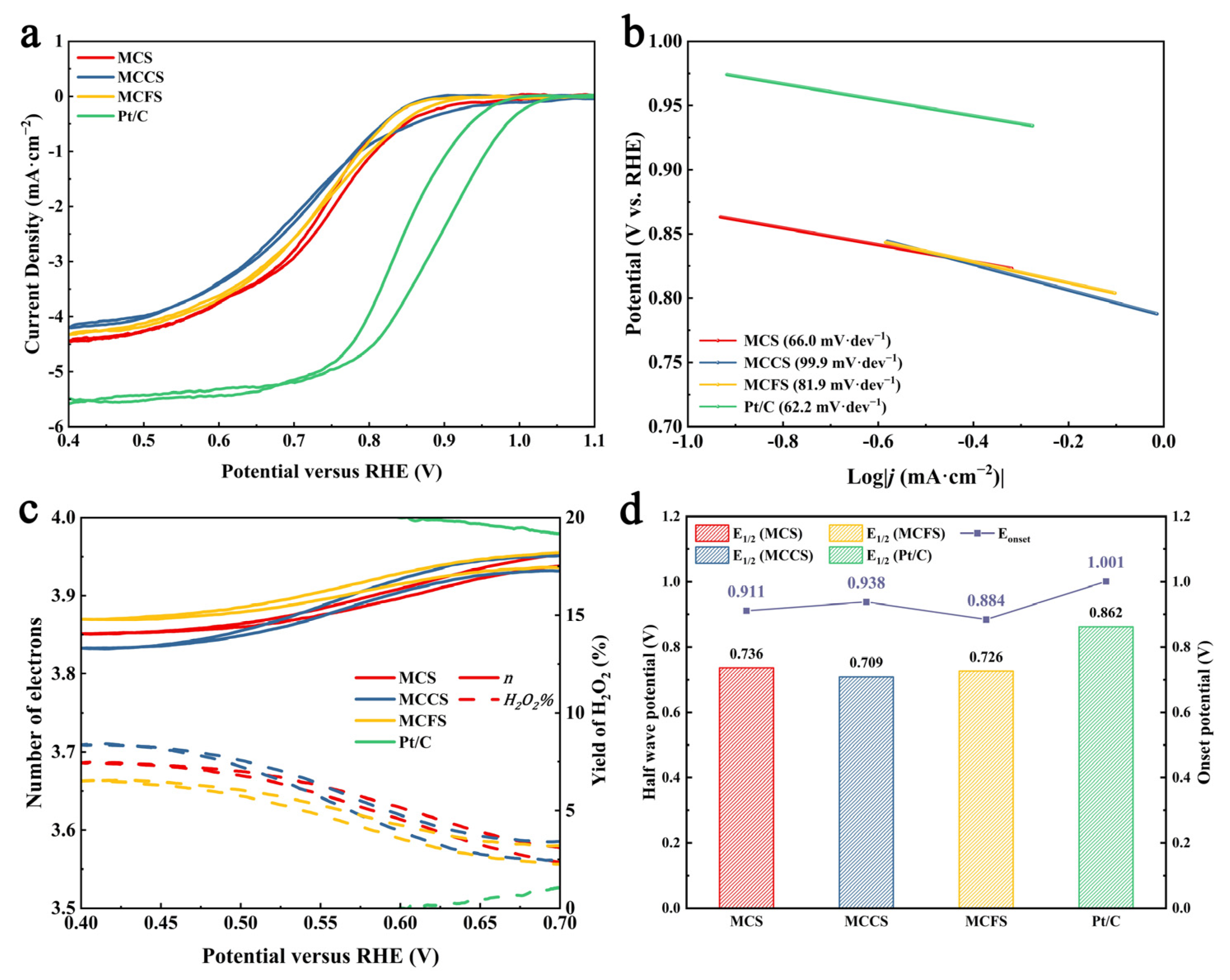
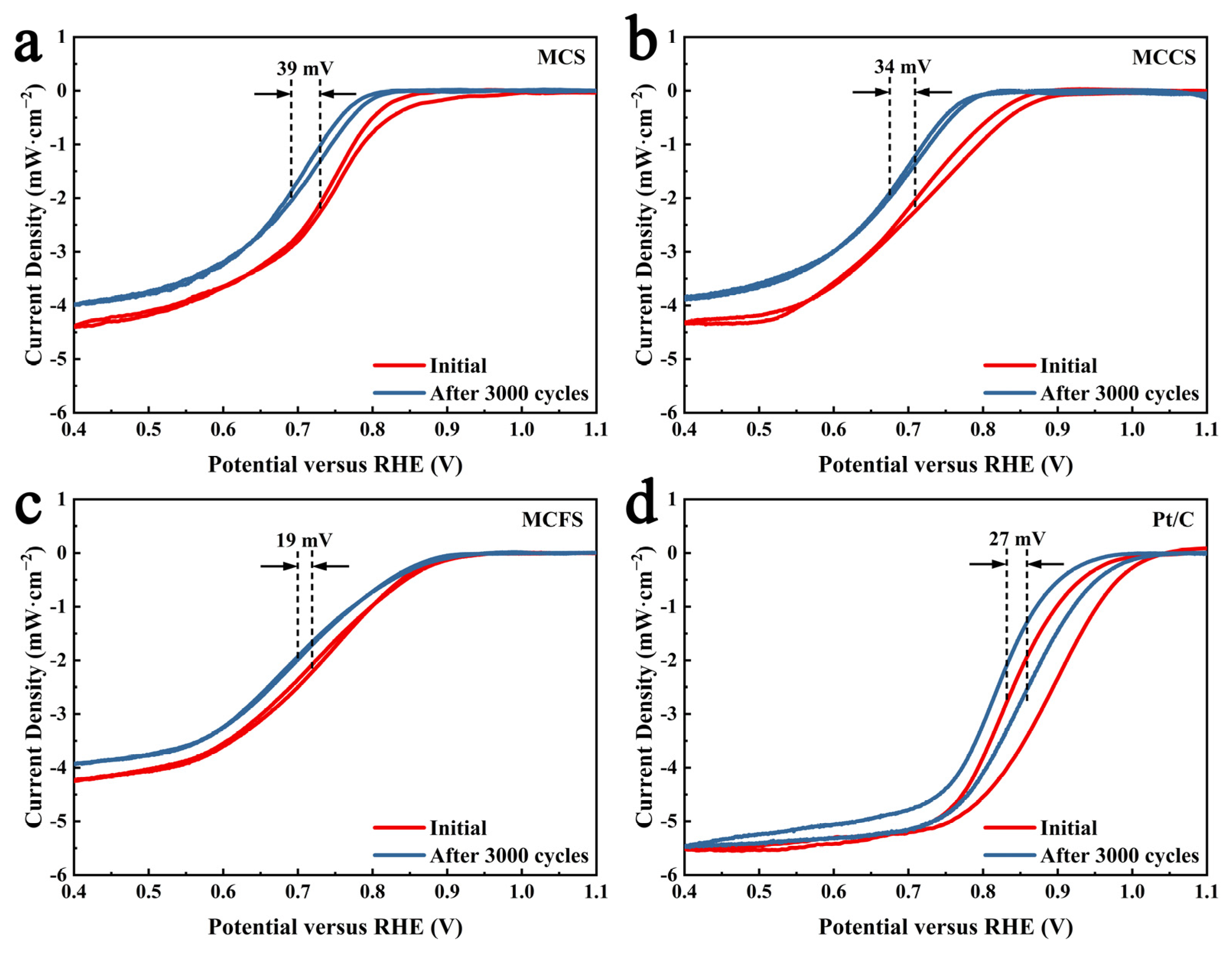
A typical three-electrode system was used to systematically study the ORR performance of the spinel oxides in 0.1 mol·L−1 O2-Saturated KOH solutions. Cyclic voltammetry (CV) was applied to MCS, MCCS, MCFS, and commercial Pt/C catalysts by using 1600 r·min−1 and 5 mV·s−1, as presented in Figure 2. It is generally believed that the effect of the glassy carbon (GC) electrode in this process is negligible [34]. As shown in Figure 2a,d, the electrocatalytic activity of MCFS for the ORR is superior to the MCCS, with a more positive ORR half-wave potential of 0.726 V vs. RHE and a higher limited current density of 4.329 mA·cm−2. But both are inferior to MCS and Pt/C. In addition, the Tafel slope, which is a criterion used for evaluating the reaction kinetics of electrocatalysts, is presented in Figure 2b. Compared with the Tafel slopes of MCCS and MCFS, which are 99.9 and 81.9 mV·dec−1, respectively, the decreased Tafel slope observed for MCS (66.0 mV·dec−1) indicates that less voltage is required for the ORR rate-limiting step with MCS. Furthermore, MCS shows the closest Tafel slope to the commercial Pt/C catalyst which means similar kinetics. To understand in depth the ORR kinetics for several spinel oxides, the ring current was collected by the rotating disk-ring electrode (RRDE) test while the electron number (n) and the yield of hydrogen peroxide ( H 2 O 2 % ) were calculated. As shown in Figure 2c, MCS, MCCS, and MCFS follow an approximately four-electron ( 4 e ) reaction path (n > 3.83) with a low hydrogen peroxide yield ( H 2 O 2 % < 8%), and approaching the level of commercial Pt/C ( n > 3.98, H 2 O 2 % < 2%). Overall, the ORR performance decreases in the order Pt/C > MCS > MCFS > MCCS. Meanwhile, spinel oxides are promising candidates for ORR. To evaluate the cycling stability, accelerated durability tests (ADTs) were conducted on the catalysts, which involved 3000 cycles between 0.6 and 1.1 V (vs. RHE) at a scan rate of 50 mV·s−1 in an O2-saturated 0.1 M KOH solution [35]. The results shown in Figure 3 indicate a gradual negative shift in the polarization curves for all four samples after cycling. Among them, MCCS and MCFS exhibited enhanced stability, with ΔE1/2 values of 34 mV and 19 mV, respectively, both lower than that of MCS (39 mV). Notably, the stability of MCFS even surpassed that of Pt/C (with a ΔE1/2 of 27 mV), suggesting that the introduction of Fe3+ contributes to the long-term stability of the catalyst.

2.3. Fuel Cell Test

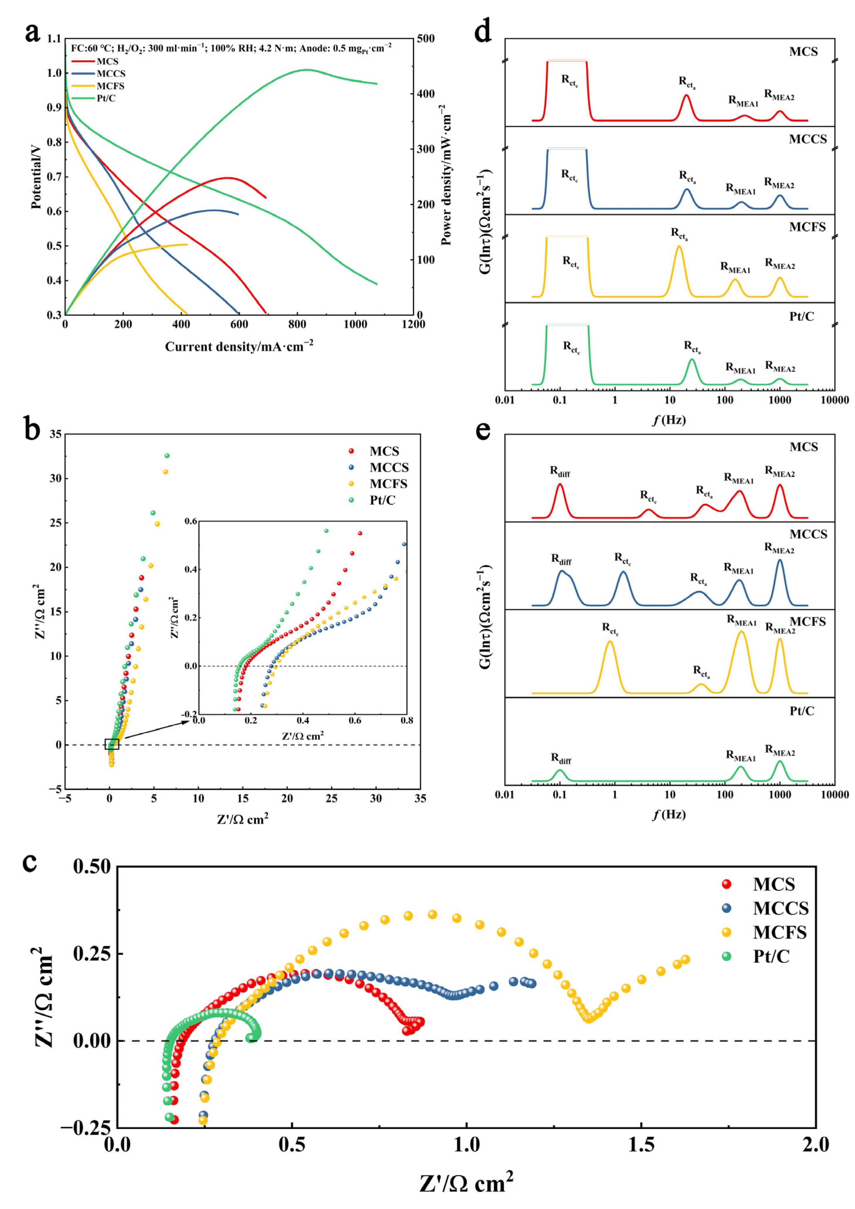
To further explore the application of the as-prepared ORR catalysts for practical AEMFC, MCS, MCCS, and MCFS were used as cathodic oxygen reduction catalysts to construct MEA, and the commercial Pt/C catalyst was also used for comparison. Figure 4a shows the polarization and power density curves of AEMFC by capitalizing on MCS, MCCS, MCFS, and Pt/C as cathodic oxygen reduction catalysts, with Pt/C as anodic catalyst. A divergence from the expectations based on RRDE measurements is observed in the actual single-cell fuel cell tests, where the peak power density (PPD) follows the order Pt/C > MCS > MCCS > MCFS, at 443.4, 248.3, 189.6, and 127.6 mW·cm−2, respectively, and the open-circuit potential (OCP) follows the order Pt/C > MCCS > MCS > MCFS, at 1.08, 0.995, 0.986, and 0.984 V, respectively.
In order to further understand the reasons why the AEMFC performances of ternary spinel differ from the RRDE test, we collected the Electrochemical Impedance Spectroscopy (EIS) data at different applied potentials. The Nyquist diagrams in Figure 4b was obtained at OCP, illustrating the equilibrium scenario for all cell configurations. Only a kinetic loop is expected in this zero-current system, as the concentration profile development for electroactive species has not been reached. Consequently, the interfacial kinetics represent the primary loss in the system. However, an additional loop is observed in the high-frequency region (enlarged area in Figure 4b) attributed to the contact capacitance within the structure of the MEA and its ohmic internal resistance, as explained by Refs. [36,37]; therefore, this impedance is associated with the ion transport in the MEA ionomer [38]. From the EIS data, it can obtain the order of the ohmic impedance of the four cells is Pt/C > MCS > MCCS > MCFS, at 0.16, 0.18, 0.29, and 0.31 Ω·cm2, respectively. The resistance spectrum is analyzed using DRT tools, and the peak position and height in the fitting results are used to analyze the reaction process. As shown in Figure 4d, according to the position of each peak, it can be divided into Rcta, Rctc, RMEA1, and RMEA2, from low to high frequency. Among them, Rcta and Rctc represent the charge transfer resistances of the anode and cathode, respectively. These resistances originate from the activation energy barriers of the respective half-reactions and are manifest as the kinetic overpotential which is directly related to the concentration of oxygen vacancies in spinel. RMEA1 and RMEA2 represent the ohmic losses at the cathode and anode, respectively. These losses arise from the ionic and electronic resistances of various cell components, including the bipolar plates, gas diffusion layers, catalyst layers, and membrane. Specifically, the ionic resistance is closely linked to the catalyst’s hydration capability, as it governs proton transport and the mobility of hydroxide ions within the membrane and ionomer. Consequently, RMEA1 is directly influenced by the quantity of adsorbed water [39,40,41]. Notably, the ternary spinel, especially the MCFS, has a higher peak than MCS and Pt/C, indicating a poor charge and ion transfer processes. In addition, under the polarized steady-state conditions with an applied potential of 0.6 V, new Nyquist and DRT diagrams were generated which were shown in Figure 4c,e. According to the polarization curve, the fuel cells are in the mixed transport limited regions. The order of the Polarization impedance of the four cells is also Pt/C > MCS > MCCS > MCFS, at 0.23, 0.64, 0.90, and 1.33 Ω·cm2, respectively. Compared to OCP, when a potential of 0.6 V is applied, the Rcta and Rctc peaks shift towards higher frequencies and lower their polarization resistance concerning the equilibrium cell state, while the RMEA1 and RMEA2 do not have a change in their characteristic frequency. Simultaneously, the Rcta and Rctc peaks disappear in the Pt/C spectrum. This disappearance can be attributed to the cell operating near the limiting current density region at 0.6 V, where the charge transfer resistance becomes significantly lower than the ion transport resistance [40]. Moreover, a new peak appears at a low-frequency region (0.5 ≤ f ≤ 1 Hz). This process is associated with a mass transport limitation (Rdiff) which typically arises from the limited diffusion rates of the reactants and products through the porous medium at high current densities, coinciding with the polarization curve which means the system is changing to a limiting current condition (mixed control). Compared to MCS, the Rdiff of MCCS has a larger peak area, indicating that it may be due to the total conversion of water or oxygen on the cathode or by the lack of hydrogen over the anode caused by clogging pores with liquid water [38]. Specifically, this peak is absent from the DRT diagram of the MCFS-based cell because, at 0.6 V, the system operates primarily within the charge-transport limitation region, where ohmic and charge transfer processes dominate. Overall, compared to MCS, MCCS and MCFS exhibit higher Rctc and RMEA1 peaks, indicating that both cathodic charge transfer and ion transfer processes are suppressed and the activity of ternary spinel is not as good as that of binary spinel.

2.4. Mechanism Analysis

The electrochemical properties and fuel cell performances discussed above indicate that the introduction of Cu2+ and Fe3+ has a detrimental effect on MCS, and MCCS and MCFS perform differently in the RRDE and fuel cell test. In the RRDE test, the adverse impact is primarily reflected in a reduction in catalytic activity, whereas, in the fuel cell test, it mainly manifests as a hindered charge and ion transfer processes. The main drawback of using RRDE is the difference in the electrochemical environment between the fuel cell and the RRDE system. The former develops an electrode–solid electrolyte interface, where accessible catalyst active sites are limited to the triple-phase boundary where the reactant gas, charge carriers, and catalyst intersect [38,42]. In contrast, the latter, the electrode–liquid electrolyte interface, allows full access of the electrolyte to the active sites for the charge carrier. However, the reactant gas concentration is limited by its solubility in the liquid medium. In addition, the electrodes are supplied with humidified gas in AEMFC, exposing the catalyst surfaces to a humid atmosphere rather than a liquid aqueous electrolyte, as is typical in RRDE system. Thus, it is not surprising that good-performing electrocatalysts in RRDE tests can often exhibit poor performance under fuel cell operation. To elucidate the inferior performance of ternary spinel catalysts relative to their binary counterparts and the discrepancies between the fuel cell and RDE test results, the structure, morphology, and valence state of catalysts were analyzed.
The pore size distribution and specific surface area are important parameters that affect the catalytic performance of catalysts [43]. In this sense, nitrogen adsorption–desorption studies and the corresponding pore size distribution analysis for MCS, MCCS, and MCFS were performed and the data were displayed in Figure 5a–d. The catalysts show a typical type-IV isotherm, suggesting that the catalyst structure is mesoporous [44]. The derived Brunauer–Emmett–Teller (BET) surface areas of MCS, MCCS, and MCFS are 86.61, 127.95, and 120.78 m2·g−1, respectively, with a pore volume of 0.32, 0.35, and 0.35 cm3·g−1, respectively. Moreover, the pore size distribution shown in the inset indicates that the apertures of the three samples are mainly concentrated between 20–60 nm and there is no significant difference among the three. Such large pores are desirable for fuel cell operation as they provide high accessibility to the active centers and play an important role in mass transfer because large pores are less likely to be blocked by liquid water. Combined with SEM, which is shown in Figure 1, it indicates that the catalyst particles prepared by freeze-drying have a high porosity and similar pore size distribution, which is beneficial for the fuel cell environment. In addition, it is also demonstrated that the introduction of Cu2+ and Fe3+ can increase the specific surface area, which may be related to their larger atomic radius.
In addition to BET gas adsorption, the electrochemical active surface area (ECSA) is commonly evaluated by determining the double-layer capacitance (Cdl) of the catalysts. It is widely accepted that the ECSA of a catalyst is proportional to its Cdl, meaning that a larger Cdl corresponds to a greater ECSA. As shown in Figure 5e–g, the Cdl of MCS, MCCS, and MCFS are obtained by fitting the CV curves at different scan rates within the potential range near OCP. According to the formula, the calculated Cdl of the synthesized catalysts follows the trend of MCCS (3.67 mF·cm−2) > MCFS (3.03 mF·cm−2) > MCS (2.98 mF·cm−2), which is consistent with the trend of the specific surface area measured by BET. The ECSA is calculated using a reference capacitance value of 40 μF·cm−2 [45] and is presented in Figure 5e. The results demonstrate that the MCCS catalyst exhibits the largest ECSA of approximately 45.36 m2·g−1, followed by MCFS (37.45 m2·g−1) and MCS (36.83 m2·g−1). Combined with the half-wave potential, it can be explained that, although MCCS has the worst ORR intrinsic activity, it can provide more reaction sites and a greater contact area, which benefits it in the fuel cell test.
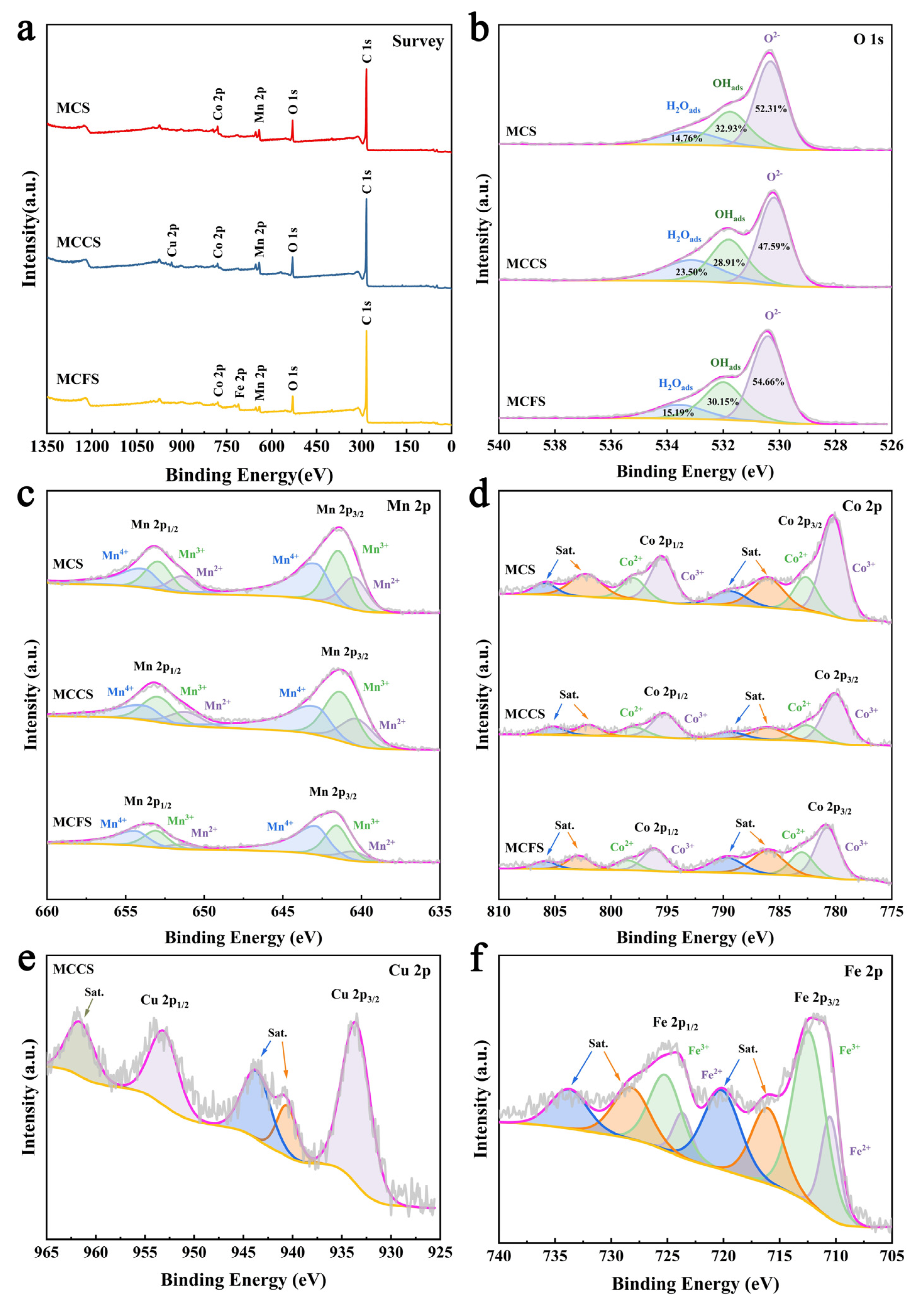
In addition to factors such as morphology and structure, the electrochemical behaviors of spinel are closely related to the valence states and oxygen vacancies. To identify the valence states of Mn, Co, Cu, Fe, and O and the surface composition of these spinel catalysts supported on carbon, X-ray photoelectron spectroscopy (XPS) measurements were carried out. As revealed in Figure 6a, XPS was used to obtain relative information on element contents and valence states, which provided the indicated BEs for the following elements: C 1s, 284.8 eV; O 1s, 530.08 eV; Mn 2p, 642.08 eV; Co 2p, 781.08 eV; Cu 2p, 934.08 eV; and Fe 2p, 711.08 eV. The typical two peaks of Cu 2p and Fe 2p represent the introduction of Cu and Fe. The O 1s single peak in Figure 6b is assigned to three subpeaks involving lattice oxygen (O2−, 530.18 eV) that comprises the spinel and hydroxyl groups (OHads, 531.78 eV) and physiosorbed or chemisorbed water molecules (H2Oads, 533.38 eV) [31,34]. The ORR process in alkaline media on cobalt manganese-based spinel catalysts can be broken down into several stages: (1) the initial adsorption of oxygen and the first electron transfer to form an intermediate oxygen species: O 2 + * O 2 * ; O 2 * + e O O H * ; (2) the cleavage of the O–O bond and a subsequent electron transfer to generate adsorbed oxygen atoms and hydroxide ions: O O H * + e O * + O H ; (3) the reduction in the adsorbed oxygen atoms via the reaction with a water molecule and the acceptance of another electron to form adsorbed hydroxide: O * + H 2 O + e O H * + O H ; (4) and, finally, the desorption of the adsorbed hydroxide, releasing the hydroxide ion and regenerating the active site: O H * + e O H + * [46,47]. Among them, O 2 * , O O H * , O * , and O H * represent the reaction intermediates generated and consumed along the oxygen reduction reaction pathway. These transient species exist only during the dynamic process of the reaction, and their surface coverage is governed by both reaction kinetics and thermodynamics. In contrast, OHads refers to the stably adsorbed hydroxyl species detected by XPS on the pristine catalyst surface prior to the electrochemical reaction. These OHads species are predominantly stabilized at surface defect sites, such as oxygen vacancies. Although they are distinct concepts, there is a strong correlation between them: A surface that can stably adsorb a large amount of OHads prior to reaction indicates that the surface possesses the following: (1) abundant oxygen vacancies, providing adsorption sites for OHads; (2) the appropriate electrophilic/nucleophilic properties, enabling stable chemical bonding with oxygen-containing species; and (3) an optimized electronic structure—this is precisely the key to modulating the adsorption strength of ORR intermediates [47]. Therefore, OHads mainly affects the ORR reaction process through the following mechanisms:
Mechanism 1: Lowering the energy barrier of the rate-determining step (RDS): O 2 * + e O O H *
The first electron transfer process of O 2 * + e O O H * is widely recognized as the rate-determining step (RDS). Oxygen vacancies, acting as positively charged defects, reduce the surrounding metal ions, creating locally electron-rich active sites, and the OHads residing on them serves as a marker of this electron-rich characteristic. This electron-rich environment significantly enhances the ability to inject electrons into the π* antibonding orbital of O2 molecules, thereby effectively weakening the O=O bond and markedly accelerating the RDS step of the formation of O O H * . Consequently, a higher OHads content indicates that the catalyst surface possesses more active sites capable of efficiently activating O2 molecules, thereby directly reducing the energy barrier of the RDS [48].
Mechanism 2: Optimizing the intermediate adsorption energy and steering the 4 e reaction path
The presence of surface OHads reflects the modulated state of the d-band center of the metal sites. A modulated d-band center optimizes the adsorption strength of key intermediates, particularly O O H * and O * . If the adsorption is too weak, the reaction cannot proceed efficiently; if it is too strong, intermediates poison the active sites. The high OHads content on our catalyst surfaces suggests an achieved optimal adsorption strength. This ensures the following: (1) the effective formation of O O H * and the subsequent bond cleavage in Step (2) O O H * + e O * + O H ; and (2) the prevention of the premature desorption of O O H * from the surface to form H2O2 (the 2 e pathway). Therefore, a higher OHads content is directly correlated with optimized intermediate adsorption, facilitated O–O bond cleavage, and guidance of the reaction efficiently along the 4 e pathway (Steps 1–4) [49]. Therefore, the OHads quantified by XPS serves as a structural descriptor that reflects the abundance and electronic properties of intrinsic active sites such as oxygen vacancies on the pristine catalyst surface. These intrinsic properties govern both the RDS barrier and the reaction pathway selectivity of the ORR, thereby playing a decisive role in determining the overall electrocatalytic activity. Apparently, the high-resolution O 1s spectrum results indicate that MCS shows the highest percentage of OHads adsorbed to surface oxygen vacancies at 32.93%, whereas the introduction of Cu2+ and Fe3+ reduces the OHads content, ultimately resulting in the ORR activity trend: MCS (32.93%) > MCFS (30.15%) > MCCS (28.91%). It should be noted that the introduction of Cu2+ results in a substantial increase in the percentage of H2Oads (23.50%), which is significantly higher than the 15.19% of MCFS. This indicates that, under humid fuel cell conditions, MCCS can adsorb more water, which can promote the Grotthuss mechanism for H+ transport [14]. As a consequence, MCCS exhibits a lower charge transfer resistance and reduced ion transport resistance with lower Rctc and RMEA1 peaks shown in Figure 4d, ultimately leading to a higher performance in the fuel cell compared to MCFS. The Mn 2p peaks are deconvoluted into multiple spin-orbit doublets as shown in Figure 6c. The doublets with BEs of 640.45/651.40 eV, 641.46/652.92 eV, and 642.88/653.83 eV are assigned to Mn2+, Mn3+, and Mn4+, respectively, in which the surfaces of these samples are mainly dominated by Mn3+ and Mn4+. Similarly, the Co 2p peaks are deconvoluted into multiple spin-orbit doublets and its associated satellite peaks as shown in Figure 6d. The doublets with BEs of 780.18/795.42 eV and 782.65/798.00 eV are assigned to Co3+ and Co2+ and the peaks with BEs of 786.00, 802.22, 789.40, and 805.90 eV, corresponding to the Co satellites peaks (Sat.), respectively. For the Cu 2p spectrum illustrated in Figure 6e, the peaks positioned at 933.54 and 953.09 eV in MCCS can be assigned to Cu2+, while the remaining features correspond to the satellite peaks. Notably, no metallic Cu or Cu+ species are detected in the sample. Furthermore, the deconvoluted Fe 2p spectrum shown in Figure 6f indicates the presence of Fe2+ and Fe3+ species at binding energies of 710.51/723.65 eV and 712.38/725.18 eV, respectively, while the remaining peaks are attributed to satellite peaks. By fitting the data, the content of different elements and valence states in the material can be calculated. For MCS, the existing research has shown that the MCS possesses a synergistic surface for ORR catalysis, with the Mn sites binding and cleaving O2, and the Co sites enriching and activating H2O, so as to facilitate the proton-coupled electron transfer processes of oxygen reduction [14]. Meanwhile, cubic spinel exhibits higher activity than tetragonal spinel due to the higher catalytic site number, stronger O2 adsorption, and higher average oxidation state of Mn [25]. With the introduction of Cu2+ and Fe3+, the crystalline phase changes from cubic to tetragonal as previously demonstrated, resulting in an inferior ORR performance and fuel cell performance of MCCS and MCFS compared to MCS. Among these modifications, the incorporation of Cu2+ not only reduces the valence state of Mn but also increases the Co3+/Co2+ ratio from 2.88 to 3.10. It is considered that Co ions with a high valence state in octahedral sites are favorable for the catalytic splitting of water [50]. Combined with the stronger hydration ability of Cu2+, the performance of MCCS in the fuel cell has been further improved.
Furthermore, the introduction of Fe3+ induces a shift of the Mn 2p and Co 2p spectra toward higher binding energies, indicating that Mn and Co ions have lost electrons, while Fe3+ has gained electrons, resulting in a mixed valence state of Fe2+ and Fe3+. The loss of electrons from Mn ions increases the proportion of Mn3+ with a 3d4 electronic configuration, which facilitates electron conduction (via hopping) and enhances the charge transfer [51]. Concurrently, the positive shift in the Co binding energy also contributes to improved catalytic activity, despite a Co3+/Co2+ ratio of only 2.68 and a degree of hydration lower than that of MCFS [52]. This is why the ORR activity of MCFS is lower than that of MCCS, while the fuel cell performance is better than MCCS. As for the superior stability of MCFS, it can be attributed to the unique behavior of Fe. Unlike Mn and Co, which undergo cyclic valence changes within the ORR potential window, Fe maintains a relatively constant local electronic structure over a broad potential range of 0.2 to 1.2 V vs. RHE, thereby acting as a stabilizer to enhance the long-term durability of the spinel catalyst [31].

3. Conclusions

In summary, MCS, MCCS, and MCFS were synthesized via hydrothermal and freeze-drying methods. Among them, MCS exhibited the highest ORR activity and fuel cell performance, with a half-wave potential of 0.736 V vs. RHE and a peak power density of 248.3 mW·cm−2. In contrast, MCCS (E1/2 = 0.709 V vs. RHE, and PPD = 189.6 mW·cm−2) demonstrated a superior performance to MCFS (E1/2 = 0.726 V vs. RHE, and PPD = 127.6 mW·cm−2) in RRDE tests but an inferior fuel cell performance. To elucidate the underlying reasons, we compared the differences between the RRDE and fuel cell testing environments. And a series of characterizations were carried out on the catalyst, while DRT analysis was performed on the single cell. The main conclusions are summarized as follows: (1) Oxygen vacancies play a dominant role in determining the electrocatalytic activity. The introduction of Cu2+ and Fe3+ transformed the crystalline phase of MCS from the cubic to tetragonal phase, which reduced the content of oxygen vacancy, weakened the oxygen adsorption, and reduced the average valence state of Mn, leading to an inferior performance compared to MCS. (2) Although Cu2+ incorporation decreased the oxygen vacancy content and reduced the ORR activity, it increased the ECSA and raised the Co3+/Co2+ ratio, thereby enhancing the hydration capability and water dissociation activity, which contributed to its superior performance in fuel cell operation. (3) Although the incorporation of Fe3+ increases the Mn3+ ratio, which improves the electron conduction and charge transfer—thereby enhancing the RRDE performance—and maintains a relatively constant local electronic structure over a wide potential range of 0.2 to 1.2 V vs. RHE, thus boosting stability, it concurrently reduces the Co3+/Co2+ ratio. This reduction impairs water adsorption under humidified gas conditions, ultimately leading to an inferior fuel cell performance. Therefore, a comprehensive evaluation of electrocatalysts requires not only RRDE measurements but also a fuel cell test. In conclusion, this work was conducted to test the hypothesis that introducing Cu2+ with ORR activity and Fe3+ with an enhanced stability into MCS could improve its overall catalytic performance and stability. It led to an unexpected outcome, for which a clear mechanistic explanation was provided.

4. Materials and Methods

4.1. Materials

Manganese (II) acetate tetrahydrate (Mn(OAc)2·4H2O, 99.0%), Cobalt(II) acetate tetrahydrate (Co(OAc)2·4H2O, 99.9%), Copper (II) nitrate trihydrate (Cu(NO3)2·3H2O, 99.0%), Iron(III) nitrate nonahydrate (Fe(NO3)3·9H2O, 99.9%), and ammonium hydroxide (NH3·H2O, ≥25%) were purchased from Aladdin (Shanghai, China). Vulcan XC-72 was purchased from Cabot (Boston, MA, USA), and 40 wt.% Pt/C was purchased from Johnson Matthey (London, UK). Nafion was purchased from Dupont (Wilmington, DE, USA). All chemicals were used as received without further purification.

4.2. Catalyst Preparation

In a typical synthesis of cubic nanocrystalline MCS supported on carbon black, 152.6 mg Vulcan XC-72R (preheated at 110 °C in air for 10 min) and 161.9 mg Co(OAc)2·4H2O were added to 77 mL deionized (DI) water. After ultrasonic mixing for 15 min, 1.3 mL NH3·H2O was added under magnetic stirring, followed with 15 min magnetic stirring. Then, Mn(OAc)2 solution (159.3 mg dissolved in 13 mL DI water) was dropped into the mixed solution while heating the mixed solution in an oil bath to 60 °C and stirring continuously for 2 h. After that, the suspension was ultrasonically mixed for 10 min, and then transferred to a 100 mL Teflon autoclave for hydrothermal reaction at 150 °C for 3 h. The resulting product was collected by centrifugation and washed with water, then freeze-dried under vacuum. MCCS and MCFS supported on carbon black were prepared in the same method.

4.3. Material Characterization

Powder X-ray diffraction (XRD) analyses were carried out with a Bruker-AXS D8-Advance X-ray powder diffractometer (Bruker, Billerica, MA, USA), and the data were recorded over the range of 10°–90° with a scanning speed of 8°·min−1. Scanning electron microscopy (SEM) images were taken with an FEI Quanta 250FEG microscope (operating voltage, 15 kV) equipped with an energy-dispersive spectrometer (EDS) analyzer (FEI Company, Hillsboro, OR, USA). Before analysis, the samples were coated with a thin Au film to provide better conductivity. Surface areas and pore size distributions were detected at −196 °C with a Micromeritics ASAP 2460 adsorption instrument (Micromeritics, Norcross, GA, USA) in conjunction with the Brunauer–Emmett–Teller (BET) and Barrett–Joyner–Halenda (BJH) methods, respectively. In addition, X-ray photoelectron spectroscopy (XPS) was performed on a Thermo Scientific K-Alpha spectrometer (Thermo Fisher Scientific, Newton, MA, USA) to identify the binding energies (BEs) of surface species.

4.4. Electrochemical Measurements

All electrochemical measurements were carried out in a three-electrode cell using an electrochemical workstation (DH7003B, DongHua Analytical, Taizhou, China) at room temperature (~25 °C). In this cell, a graphite rod was used as the counter electrode and a Hg/HgO electrode (aqueous 1 M KOH internal solution) was used as reference electrode. The working electrode was a rotating disk-ring electrode (Hydrogen Core Technology Co., Ltd., Wuxi, China) with a Pt ring and a glassy carbon (GC) disk (geometric surface areas: disk, 0.2472 cm2; ring, 0.1859 cm2).
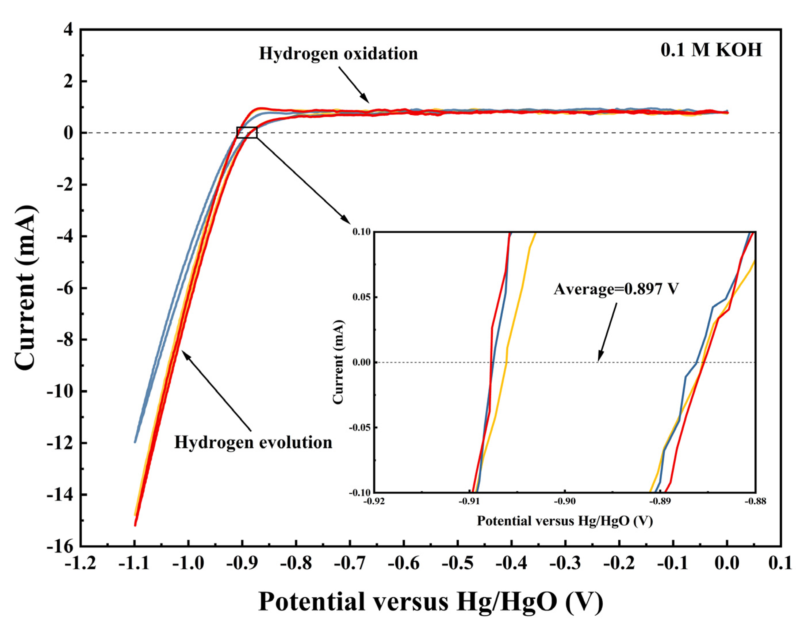
The Hg/HgO reference electrode was calibrated with respect to the reversible hydrogen electrode (RHE), as shown in Figure 7. The calibration was performed in an H2-saturated 0.1 M KOH solution with a Pt sheet electrode as the working electrode and an Hg/HgO as the reference electrode. With the continuous H2 conveying during calibration, the average of the two potentials at which the current crossed zero was taken to be the thermodynamic potential for the hydrogen electrode reactions. Therefore, in 0.1 M KOH, E(RHE) = E(Hg/HgO) + 0.897 V.
The catalyst ink was a suspension of catalyst powder (5.0 mg, 40 wt.%), isopropanol (975 μL), and Nafion solution (25 μL, 5 wt.%) formed by ultrasonication for 60 min. For the test of ORR, 10 μL ink was dropped on the RRDE electrode with a loading mass of 80.9 μg·cm−2 and dried in air at room temperature. This loading was commonly used and empirically confirmed to form a uniform, thin catalyst film on the glassy carbon electrode that provides a strong electrochemical signal without introducing significant mass transport limitations. Prior to electrochemical measurements, the cyclic voltammetry (CV) test was performed at a potential sweep rate of 50 mV·s−1 from 0.4 to 1.2 V (vs. RHE) for 50 cycles in Ar-saturated 0.1 M KOH electrolyte to active the electrode. The working electrodes were scanned between 0.4 to 1.2 V (vs. RHE) at 5 mV·s−1 and 1600 rpm in O2-saturated 0.1 M KOH. It should be pointed out that the capacitive background currents in CV curves measured in Ar-saturated 0.1 M KOH solution were subtracted from the raw ORR data.
To evaluate the hydrogen peroxide yield ( H 2 O 2 % ) and the electron transfer number ( n ) of the catalysts, the Pt ring potential was set to 1.3 V (vs. RHE) in the RRDE measurements. The H 2 O 2 % and n were calculated using the following equation:
H 2 O 2 % = 200 × I R / N 0 I R N 0 + I D  
n = 4 × I D I R N 0 + I D  
where n is the average number of electrons transferred per reacting oxygen, IR and ID are the ring and disk currents, respectively, and N0 = 0.37 is the collection efficiency of the RRDE.
The accelerated durability tests (ADTs) were performed at room temperature (~25 °C) in O2-saturated 0.1 M KOH solution. The cyclic potential sweeps were applied to RHE from 0.6 to 1.1 V at a scan rate of 50 mV·s−1 for 3000 cycles, and the initial and final CV curves were collected.

4.5. Fuel Cell Tests

Regarding the preparation of catalyst ink, 30 mg of catalyst, 162 mg of binder (5 wt.%, PiperION-A5-HCO3, Versogen, Wilmington, DE, USA), 0.3 mL of DI water, and 6 mL of isopropanol were mixed in ice bath by ultrasonication for 60 minutes until the formation of a well-dispersed solution. Subsequently, with the support of a vacuum adsorption heating platform, catalyst ink was sprayed onto a gas diffusion layer (GDL, 29BC, Sigracet, SGL Carbon, Wiesbaden, Germany) with an active area of 4 cm2 to prepare a gas diffusion electrode (GDE). Anode catalyst was commercial Pt/C with the loading amount of 0.5 mgPt·cm−2. The cathode catalysts used spinel catalyst with the loadings of 0.8 mgmetal·cm−2, while a Pt/C catalyst with a loading of 0.5 mgPt·cm−2 was used as a comparison. Before forming the MEA by pressing the cathode and anode to the two sides of the AEM (PiperION-A20-HCO3, Versogen, Wilmington, DE, USA), the GDE and AEM were immersed in a 1 M KOH solution for 12 h. Following this step, the AEM, GDE and two gaskets were assembled in the cell using a torch wrench with the desired level of 4.2 N·m. The fuel cell performance was tested at 60 °C, 100% relative humidity (RH), and the flow rate of H2/O2 gas=300 ml·min−1 without the back pressure at both electrode sides.

Author Contributions

Conceptualization, methodology, and writing—original draft, W.J.; validation, R.S.; software, J.Y.; formal analysis, H.P., W.Z. and X.Z.; funding acquisition, supervision, and writing—review and editing, J.Z. All authors have read and agreed to the published version of the manuscript.

Funding

This work was funded by the National Key Research and Development Program of China (2022YFB4002603).

Data Availability Statement

The data will be made available upon request.

Conflicts of Interest

The authors declare that they have no known competing financial interests or personal relationships that could have appeared to influence the work reported in this paper.

References

  1. Cigolotti, V.; Genovese, M.; Fragiacomo, P. Comprehensive Review on Fuel Cell Technology for Stationary Applications as Sustainable and Efficient Poly-Generation Energy Systems. Energies 2021, 14, 4963. [Google Scholar] [CrossRef]
  2. Debe, M.K. Electrocatalyst approaches and challenges for automotive fuel cells. Nature 2012, 486, 43–51. [Google Scholar] [CrossRef]
  3. Dunn, B.; Kamath, H.; Tarascon, J.M. Electrical Energy Storage for the Grid: A Battery of Choices. Science 2011, 334, 928–935. [Google Scholar] [CrossRef] [PubMed]
  4. Zhao, Y.G.; Saseendran, D.P.A.; Huang, C.; Triana, C.A.; Marks, W.R.; Chen, H.; Zhao, H.; Patzke, G.R. Oxygen Evolution/Reduction Reaction Catalysts: From In Situ Monitoring and Reaction Mechanisms to Rational Design. Chem. Rev. 2023, 123, 6257–6358. [Google Scholar] [CrossRef] [PubMed]
  5. Xiong, Y.; Yang, Y.; Joress, H.; Padgett, E.; Gupta, U.; Yarlagadda, V.; Agyeman-Budu, D.N.; Huang, X.; Moylan, T.E.; Zeng, R.; et al. Revealing the atomic ordering of binary intermetallics using in situ heating techniques at multilength scales. Proc. Natl. Acad. Sci. USA 2019, 116, 1974–1983. [Google Scholar] [CrossRef] [PubMed]
  6. Xu, H.; Wang, D.; Yang, P.X.; Du, L.; Lu, X.Y.; Li, R.P.; Liu, L.L.; Zhang, J.Q.; An, M.Z. A hierarchically porous Fe-N-C synthesized by dual melt-salt-mediated template as advanced electrocatalyst for efficient oxygen reduction in zinc-air battery. Appl. Catal. B-Environ. Energy 2022, 305, 121040. [Google Scholar] [CrossRef]
  7. Yang, Y.; Xiong, Y.; Holtz, M.E.; Feng, X.R.; Zeng, R.; Chen, G.; DiSalvo, F.J.; Muller, D.A.; Abruña, H.D. Octahedral spinet electrocatalysts for alkaline fuel cells. Proc. Natl. Acad. Sci. USA 2019, 116, 24425–24432. [Google Scholar] [CrossRef]
  8. Jin, Y.M.; Su, L.X.; Jia, H.N.; Men, Y.; Luo, W. Nickel-Based Electrocatalysts for Hydrogen Oxidation Reaction Under Alkaline Electrolytes. ChemCatChem 2023, 15, e202300056. [Google Scholar] [CrossRef]
  9. Yang, Y.; Peltier, C.R.; Zeng, R.; Schimmenti, R.; Li, Q.H.; Huang, X.; Yan, Z.F.; Potsi, G.; Selhorst, R.; Lu, X.Y.; et al. Electrocatalysis in Alkaline Media and Alkaline Membrane-Based Energy Technologies. Chem. Rev. 2022, 122, 6117–6321. [Google Scholar] [CrossRef]
  10. Adabi, H.; Shakouri, A.; Ul Hassan, N.; Varcoe, J.R.; Zulevi, B.; Serov, A.; Regalbuto, J.R.; Mustain, W.E. High-performing commercial Fe-N-C cathode electrocatalyst for anion-exchange membrane fuel cells. Nat. Energy 2021, 6, 834–843. [Google Scholar] [CrossRef]
  11. Lu, X.Y.; Li, Y.Q.; Yang, P.X.; Wan, Y.B.; Wang, D.; Xu, H.; Liu, L.L.; Xiao, L.H.; Li, R.P.; Wang, G.Z.; et al. Atomically dispersed Fe-N-C catalyst with densely exposed Fe-N4 active sites for enhanced oxygen reduction reaction. Chem. Eng. J. 2024, 485, 149529. [Google Scholar] [CrossRef]
  12. Huang, M.X.; Zhu, X.Y.; Shi, W.W.; Qin, Q.Q.; Yang, J.; Liu, S.S.; Chen, L.F.; Ding, R.M.; Gan, L.; Yin, X. Manipulating the coordination dice: Alkali metals directed synthesis of Co-N-C catalysts with CoN4 sites. Sci. Adv. 2025, 11, eads6658. [Google Scholar] [CrossRef] [PubMed]
  13. Wang, W.; Liu, E.; Hu, Y.C.; Jiao, L.; Kolla, P.; Liu, Y.C.; Tang, M.H.; Luo, J.; Sun, Q.; Chen, S.L.; et al. Understanding the ORR Electrocatalysis on Co-Mn Oxides. J. Phys. Chem. C 2021, 125, 25470–25477. [Google Scholar] [CrossRef]
  14. Wang, Y.; Yang, Y.; Jia, S.F.; Wang, X.M.; Lyu, K.J.; Peng, Y.Q.; Zheng, H.; Wei, X.; Ren, H.; Xiao, L.; et al. Synergistic Mn-Co catalyst outperforms Pt on high-rate oxygen reduction for alkaline polymer electrolyte fuel cells. Nat. Commun. 2019, 10, 1506. [Google Scholar] [CrossRef] [PubMed]
  15. Zeng, R.; Yang, Y.; Feng, X.R.; Li, H.Q.; Gibbs, L.M.; DiSalvo, F.J.; Abruña, H.D. Nonprecious transition metal nitrides as efficient oxygen reduction electrocatalysts for alkaline fuel cells. Sci. Adv. 2022, 8, eabj1584. [Google Scholar] [CrossRef]
  16. Shui, Z.Y.; Tian, H.Y.; Yu, S.L.; Xiao, H.; Zhao, W.; Chen, X. La0.75Sr0.25MnO3-based perovskite oxides as efficient and durable bifunctional oxygen electrocatalysts in rechargeable Zn-air batteries. Sci. China-Mater. 2023, 66, 1002–1012. [Google Scholar] [CrossRef]
  17. Hughes, L.; Roy, A.; Downing, C.; Browne, M.P.; Zhussupbekova, A.; Shvets, I.V.; Nicolosi, V. Surface Reduced Manganese States as a Source of Oxygen Reduction Activity in BaMnO3. Adv. Funct. Mater. 2023, 33, 2214883. [Google Scholar] [CrossRef]
  18. Tegl, G.; Hanson, J.; Chen, H.M.; Kwan, D.H.; Santana, A.G.; Withers, S.G. Facile Formation of β-thioGlcNAc Linkages to Thiol-Containing Sugars, Peptides, and Proteins using a Mutant GH20 Hexosaminidase. Angew. Chem.-Int. Ed. 2019, 58, 1632–1637. [Google Scholar] [CrossRef]
  19. Wu, C.H.; Liu, C.; Su, D.; Xin, H.L.L.; Fang, H.T.; Erens, B.; Zhang, S.; Murray, C.B.; Salmeron, M.B. Bimetallic synergy in cobalt-palladium nanocatalysts for CO oxidation. Nat. Catal. 2019, 2, 78–85. [Google Scholar] [CrossRef]
  20. Huang, J.J.; Yang, Y.; Weinstock, D.; Bundschu, C.R.; Li, Q.H.; Sarker, S.; Ruff, J.P.C.; Arias, T.A.; Abruna, H.D.; Singer, A. Multimodal in situ X-ray mechanistic studies of a bimetallic oxide electrocatalyst in alkaline media. Nat. Catal. 2025, 8, 116–125. [Google Scholar] [CrossRef]
  21. Sun, J.; Xue, H.; Zhang, Y.F.; Zhang, X.L.; Guo, N.K.; Song, T.S.; Dong, H.L.; Kong, Y.; Zhang, J.W.; Wang, Q. Unraveling the Synergistic Effect of Heteroatomic Substitution andVacancy Engineering in CoFe2O4 for Superior Electrocatalysis Performance. Nano Lett. 2022, 22, 3503–3511. [Google Scholar] [CrossRef]
  22. Harada, M.; Kotegawa, F.; Kuwa, M. Structural Changes of Spinel MCo2O4 (M = Mn, Fe, Co, Ni, and Zn) Electrocatalysts during the Oxygen Evolution Reaction Investigated by In Situ X-ray Absorption Spectroscopy. ACS Appl. Energy Mater. 2022, 5, 278–294. [Google Scholar] [CrossRef]
  23. Celorrio, V.; Leach, A.S.; Huang, H.L.; Hayama, S.; Freeman, A.; Inwood, D.W.; Fermin, D.J.; Russell, A.E. Relationship between Mn Oxidation State Changes and Oxygen Reduction Activity in (La,Ca)MnO3 as Probed by In Situ XAS and XES. ACS Catal. 2021, 11, 6431–6439. [Google Scholar] [CrossRef]
  24. Cheng, F.Y.; Shen, J.A.; Peng, B.; Pan, Y.D.; Tao, Z.L.; Chen, J. Rapid room-temperature synthesis of nanocrystalline spinels as oxygen reduction and evolution electrocatalysts. Nat. Chem. 2011, 3, 79–84. [Google Scholar] [CrossRef]
  25. Li, C.; Han, X.P.; Cheng, F.Y.; Hu, Y.X.; Chen, C.C.; Chen, J. Phase and composition controllable synthesis of cobalt manganese spinel nanoparticles towards efficient oxygen electrocatalysis. Nat. Commun. 2015, 6, 7345. [Google Scholar] [CrossRef]
  26. Tang, W.Q.; Tang, J.Y.; Liao, K.M.; Shao, Z.P. Self-reconstruction of highly active NiCo2O4 with triple-continuous transfer of electrons, ions, and oxygen for Zn-air batteries. Chem. Eng. J. 2023, 455, 140855. [Google Scholar] [CrossRef]
  27. Liu, Y.; Ying, Y.R.; Fei, L.F.; Liu, Y.; Hu, Q.Z.; Zhang, G.G.; Pang, S.Y.; Lu, W.; Mak, C.L.; Luo, X.; et al. Valence Engineering via Selective Atomic Substitution on Tetrahedral Sites in Spinel Oxide for Highly Enhanced Oxygen Evolution Catalysis. J. Am. Chem. Soc. 2019, 141, 8136–8145. [Google Scholar] [CrossRef]
  28. Zhou, M.; Wang, H.S.; Zhang, L.H.; Li, C.; Kumbhar, A.; Abruña, H.D.; Fang, J.Y. Facet Impact of CuMn2O4 Spinel Nanocatalysts on Enhancement of the Oxygen Reduction Reaction in Alkaline Media. ACS Catal. 2022, 12, 13663–13670. [Google Scholar] [CrossRef]
  29. Wang, Z.P.; Wu, P.Y.; Zou, X.B.; Wang, S.; Du, L.; Ouyang, T.; Liu, Z.Q. Optimizing the Oxygen-Catalytic Performance of Zn-Mn-Co Spinel by Regulating the Bond Competition at Octahedral Sites. Adv. Funct. Mater. 2023, 33, 2214275. [Google Scholar] [CrossRef]
  30. Chen, B.; Miao, H.; Yin, M.M.; Hu, R.G.; Xia, L.; Zhang, C.F.; Yuan, J.L. Mn-based spinels evolved from layered manganese dioxides at mild temperature for the robust flexible quasi-solid-state zinc-air batteries. Chem. Eng. J. 2021, 417, 129179. [Google Scholar] [CrossRef]
  31. Xiong, Y.; Yang, Y.; Feng, X.R.; DiSalvo, F.J.; Abruña, H.D. A Strategy for Increasing the Efficiency of the Oxygen Reduction Reaction in Mn-Doped Cobalt Ferrites. J. Am. Chem. Soc. 2019, 141, 4412–4421. [Google Scholar] [CrossRef]
  32. Cermenek, B.; Genorio, B.; Winter, T.; Wolf, S.; Connell, J.G.; Roschger, M.; Letofsky-Papst, I.; Kienzl, N.; Bitschnau, B.; Hacker, V. Alkaline Ethanol Oxidation Reaction on Carbon Supported Ternary PdNiBi Nanocatalyst using Modified Instant Reduction Synthesis Method. Electrocatalysis 2020, 11, 203–214. [Google Scholar] [CrossRef]
  33. Gillot, B.; El Guendouzi, M.; Kharroubi, M.; Tailhades, P.; Metz, R.; Rousset, A. Phase transformation-related kinetics in the oxidation of a manganese mixed oxide with a spinel structure. Mater. Chem. Phys. 1989, 24, 199–208. [Google Scholar] [CrossRef]
  34. Zhu, Y.L.; Zhou, W.; Yu, J.; Chen, Y.B.; Liu, M.L.; Shao, Z.P. Enhancing Electrocatalytic Activity of Perovskite Oxides by Tuning Cation Deficiency for Oxygen Reduction and Evolution Reactions. Chem. Mater. 2016, 28, 1691–1697. [Google Scholar] [CrossRef]
  35. Bai, J.; Zhao, T.; Xu, M.; Mei, B.; Yang, L.; Shi, Z.; Zhu, S.; Wang, Y.; Jiang, Z.; Zhao, J.; et al. Monosymmetric Fe-N4 sites enabling durable proton exchange membrane fuel cell cathode by chemical vapor modification. Nat. Commun. 2024, 15, 4219. [Google Scholar] [CrossRef]
  36. Yuan, X.-Z.; Song, C.; Wang, H.; Zhang, J. Electrochemical Impedance Spectroscopy in PEM Fuel Cells: Fundamentals and Applications; Springer: London, UK, 2010. [Google Scholar]
  37. Ahn, S.; Tatarchuk, B.J. Air electrode: Identification of intraelectrode rate phenomena via ac impedance. J. Electrochem. Soc. 1995, 142, 4169. [Google Scholar] [CrossRef]
  38. Romero-Castañón, T.; Arriaga, L.G.; Cano-Castillo, U. Impedance spectroscopy as a tool in the evaluation of MEA’s. J. Power Sources 2003, 118, 179–182. [Google Scholar] [CrossRef]
  39. León, M.I.; Romero-Castañón, T.; Flores-Hernández, J.R.; Nava, J.L. Experimental determination of HOR and ORR kinetic parameters in an AEMFC by the distribution of relaxation times method. J. Power Sources 2025, 629, 236000. [Google Scholar] [CrossRef]
  40. Douglin, J.C.; Vijaya Sankar, K.; Biancolli, A.L.G.; Santiago, E.I.; Tsur, Y.; Dekel, D.R. Quantifying the resistive losses of the catalytic layers in anion-exchange membrane fuel cells. ChemSusChem 2023, 16, e202301080. [Google Scholar] [CrossRef]
  41. Risch, M. Perovskite electrocatalysts for the oxygen reduction reaction in alkaline media. Catalysts 2017, 7, 154. [Google Scholar] [CrossRef]
  42. Wang, Q.; Hu, Z.Y.; Xu, L.F.; Li, J.Q.; Gan, Q.Q.; Du, X.L.; Ouyang, M.G. A comparative study of equivalent circuit model and distribution of relaxation times for fuel cell impedance diagnosis. Int. J. Energy Res. 2021, 45, 15948–15961. [Google Scholar] [CrossRef]
  43. Jayaramulu, K.; Dubal, D.P.; Nagar, B.; Ranc, V.; Tomanec, O.; Petr, M.; Datta, K.K.R.; Zboril, R.; Gómez-Romero, P.; Fischer, R.A. Ultrathin Hierarchical Porous Carbon Nanosheets for High-Performance Supercapacitors and Redox Electrolyte Energy Storage. Adv. Mater. 2018, 30, 1705789. [Google Scholar] [CrossRef]
  44. Baldovino-Medrano, V.G.; Niño-Celis, V.; Giraldo, R.I. Systematic Analysis of the Nitrogen Adsorption-Desorption Isotherms Recorded for a Series of Materials Based on Microporous-Mesoporous Amorphous Aluminosilicates Using Classical Methods. J. Chem. Eng. Data 2023, 68, 2512–2528. [Google Scholar] [CrossRef]
  45. McCrory, C.C.L.; Jung, S.H.; Peters, J.C.; Jaramillo, T.F. Benchmarking Heterogeneous Electrocatalysts for the Oxygen Evolution Reaction. J. Am. Chem. Soc. 2013, 135, 16977–16987. [Google Scholar] [CrossRef]
  46. Bundschu, C.R.; Ahmadi, M.; Méndez-Valderrama, J.F.; Yang, Y.; Abruña, H.D.; Arias, T.A. Oxygen Reduction Pathway for Spinel Metal Oxides in Alkaline Media: An Experimentally Supported Ab Initio Study. J. Am. Chem. Soc. 2024, 146, 4680–4686. [Google Scholar] [CrossRef]
  47. Ji, Q.Q.; Bi, L.; Zhang, J.T.; Cao, H.J.; Zhao, X.S. The role of oxygen vacancies of ABO3 perovskite oxides in the oxygen reduction reaction. Energy Environ. Sci. 2020, 13, 1408–1428. [Google Scholar] [CrossRef]
  48. Cui, X.; Gao, L.K.; Lu, C.H.; Ma, R.; Yang, Y.K.; Lin, Z.Q. Rational coordination regulation in carbon-based single-metal-atom catalysts for electrocatalytic oxygen reduction reaction. Nano Converg. 2022, 9, 34. [Google Scholar] [CrossRef]
  49. Yang, Z.; Yang, S.H.; Tang, Y.; Wang, G.; Pang, H.; Yu, F. Inhibiting demetalation of Zn-N-C via bimetallic CoZn alloy for an efficient and durable oxygen reduction reaction. J. Colloid Interface Sci. 2025, 689, 137276. [Google Scholar] [CrossRef]
  50. Joya, K.S.; de Groot, H.J.M. Controlled Surface-Assembly of Nanoscale Leaf-Type Cu-Oxide Electrocatalyst for High Activity Water Oxidation. ACS Catal. 2016, 6, 1768–1771. [Google Scholar] [CrossRef]
  51. Cheng, F.Y.; Zhang, T.R.; Zhang, Y.; Du, J.; Han, X.P.; Chen, J. Enhancing Electrocatalytic Oxygen Reduction on MnO2 with Vacancies. Angew. Chem.-Int. Ed. 2013, 52, 2474–2477. [Google Scholar] [CrossRef]
  52. Masa, J.; Weide, P.; Peeters, D.; Sinev, I.; Xia, W.; Sun, Z.Y.; Somsen, C.; Muhler, M.; Schuhmann, W. Amorphous Cobalt Boride (Co2B) as a Highly Efficient Nonprecious Catalyst for Electrochemical Water Splitting: Oxygen and Hydrogen Evolution. Adv. Energy Mater. 2016, 6, 1502313. [Google Scholar] [CrossRef]
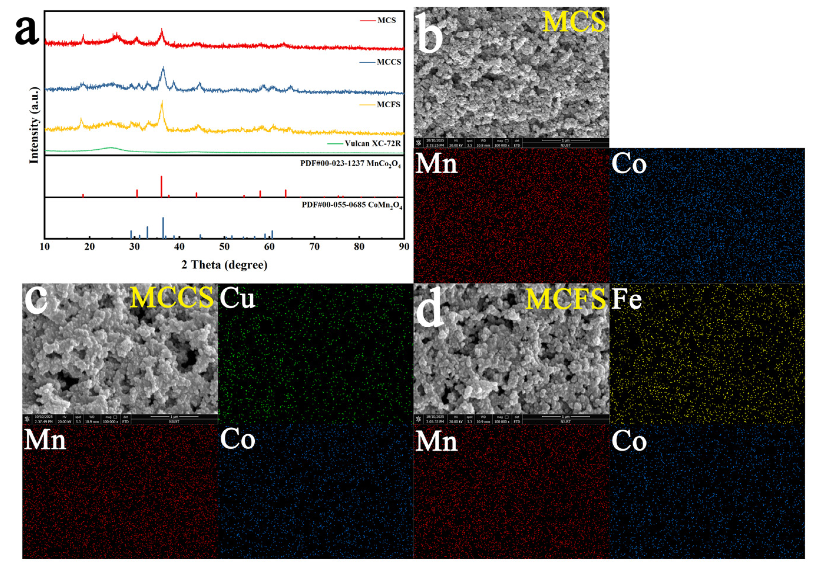
Figure 1. (a) XRD of MCS, MCCS, and MCFS and Vulcan XC-72R; SEM images and EDS mapping images of (b) MCS, (c) MCCS, and (d) MCFS.
Catalysts 15 01031 g001
Figure 2. (a) ORR at 1600 r·min−1 and 5 mV·s−1 in 0.1 mol·L−1 O2-Saturated KOH, and the curve for a commercial Pt/C catalyst is also shown for comparison; (b) Tafel plots for MCS, MCCS, MCFS, and Pt/C; (c) electron transfer numbers ( n ) and yield of hydrogen peroxide ( H 2 O 2 % ) for MCS, MCCS, MCFS, and Pt/C; and (d) half-wave potential (E1/2) for MCS, MCCS, MCFS, and Pt/C.
Catalysts 15 01031 g002
Figure 3. Polarization profiles at 1600 r·min−1 and 5 mV·s−1 in 0.1 mol·L−1 O2-Saturated KOH of (a) MCS, (b) MCCS, (c) MCFS, and (d) Pt/C after 3000 cycles of stability testing.
Catalysts 15 01031 g003
Figure 4. (a) Polarization and power density plots of AEMFC with MCS, MCCS, MCFS, and Pt/C as cathode catalysts; Nyquist plots of AEMFC at (b) open-circuit potential (OCP) and (c) 0.6 V; comparison diagram of DRT curves of AEMFC at (d) OCP, and (e) 0.6 V. Regularization parameter λ = 1 × 10⁻⁴.
Catalysts 15 01031 g004
Figure 5. Nitrogen adsorption–desorption isotherm and pore size distribution (inset) of (a) MCS, (b) MCCS, and (c) MCFS; (d) BET Surface area and Electrochemical Active Surface area for MCS, MCCS, and MCFS; CV curves of (e) MCS, (f) MCCS, and (g) MCFS at the different scan rates; and (h) double-layer capacitance fitting curves of MCS, MCCS, and MCFS.
Catalysts 15 01031 g005
Figure 6. XPS spectroscopy of MCS, MCCS, and MCFS: (a) survey; (b) O 1s; (c) Mn 2p; (d) Co 2p; (e) Cu 2p; and (f) Fe 2p.
Catalysts 15 01031 g006
Figure 7. CV curves of Hg/HgO electrode calibration in H2-Saturated 0.1 M KOH.
Catalysts 15 01031 g007
Disclaimer/Publisher’s Note: The statements, opinions and data contained in all publications are solely those of the individual author(s) and contributor(s) and not of MDPI and/or the editor(s). MDPI and/or the editor(s) disclaim responsibility for any injury to people or property resulting from any ideas, methods, instructions or products referred to in the content.