Article

Investigation of Pore Size on the Hydrogen Evolution Reaction of 316L Stainless Steel Porous Electrodes

by
Victor Manuel Solorio
1,
Luis Olmos
2,
Melina Velasco-Plascencia
1,
Héctor J. Vergara-Hernández
1,*,
Julio C. Villalobos
1,
Mario Misael Machado López
1 and
Juan Manuel Salgado López
3
1
Tecnológico Nacional de México, Instituto Tecnológico de Morelia, Avenida Tecnológico No. 1500, Lomas de Santiaguito, Morelia 58120, Mexico
2
Instituto de Investigaciones en Ciencias de la Tierra—INICIT, Universidad Michoacana de San Nicolás de Hidalgo, Avenida Francisco J. Múgica S/N Ciudad Universitaria, Morelia 58040, Mexico
3
Centro de Ingeniería y Desarrollo Industrial, Querétaro 76125, Mexico
*
Author to whom correspondence should be addressed.
Catalysts 2025, 15(1), 38; https://doi.org/10.3390/catal15010038
Submission received: 20 November 2024 / Revised: 27 December 2024 / Accepted: 30 December 2024 / Published: 3 January 2025

Abstract

:
This work aims to analyze the effect of pore size on the catalytic reaction of 316L stainless steel electrodes. Porous compacts were fabricated using the space holder technique and sintering at low temperatures. The fabricated porous compacts were characterized using computed tomography and the hydrogen evolution reaction was evaluated under 0.5 M and 1.5 M NaOH. Results indicate that porosity is well controlled by the pore formers, which allows different pore size distributions of pores with similar relative density values to be obtained. The pores are fully interconnected, allowing the passing of fluid throughout the compacts. Permeability is sensitive to the pore size, increasing as the pore size does. The catalytic activity of hydrogen evolution reaction HER is improved as the pore volume and pore size increase concerning the compact fabricated without pore formers. The compact that showed higher Cdl and Rf values was fabricated with S100 pore formers, which means a higher active area that favors the HER. It can be concluded that porosity enhances HER reactivity. However, larger pores are not beneficial due to a more significant permeability value.

1. Introduction

Hydrogen is considered an essential clean and alternative energy source due to its multiple large-scale applications requiring high consumption and production. Technologies that dominate hydrogen production include natural gas reforming, coal gasification, heavy oil reforming, and, to a lesser extent, the alkaline electrolysis process. The latter is one of the simplest methods and most used at the industrial scale, with the advantage of producing high-purity hydrogen (<99.99%) [1]. However, this electrochemical process consumes a large amount of electrical energy. For this reason, the study of high-performance materials as electrodes aims to improve the hydrogen evolution reaction (HER) [2]. In order to increase hydrogen production, the electrodes used in industrial electrolyzer equipment require specific characteristics such as good catalytic activity, a large surface area, chemical and mechanical stability, and a low cost [3,4,5]. Noble metals such as Pt and Ru are among the most active and stable materials, but their high cost and limited abundance are the biggest obstacles to their industrial application. The most crucial objective in electrocatalysis is to replace these metals with catalytic materials that have a lower cost, such as Fe, Ni, or Co [1,6,7]. 316L stainless steel (SS) is frequently used in electrodes for alkaline electrolysis due to its stability, electrocatalytic activity, relatively low cost, and high corrosion resistance [8,9,10]. One potential avenue to further improve the material’s performance and broaden its applications is through the introduction of controlled porosity [11], which increases the surface area of porous electrodes that can be processed by powder metallurgy technique [12,13]. This processing route not only improves the strength and durability of the material but also allows for the formation of intricate structures and complex shapes [14]. Recent research has demonstrated that by optimizing the manufacturing process parameters, particularly during the solid-state sintering stage, the porous structure and properties of 316L SS can be tailored to specific requirements [15,16,17]. There are different techniques for making tailored porosities, such as hot isostatic pressing [18,19], slurry foaming [20], space holders [21,22], and additive manufacturing [23,24]. Among those techniques, the space holder is the most helpful method for achieving structures with an open interconnected porous structure with controlled pore size and shape [25,26]. Interconnectivity among those pores, created during the sintering process, provides a pathway for efficient fluid flow, enabling better diffusion and faster reaction rates [27,28].
Furthermore, the combination of 316L SS powders with a space holder and controlled sintering conditions offers several benefits. First, it allows the production of complex and customized structures to optimize fluid diffusion and maximize surface area [29], further enhancing efficiency. Second, the use of stainless steel, known for its durability and resistance to corrosion, ensures the longevity and reliability of the hydrogen production process [30,31,32,33].
The main objective of this research is to fabricate porous 316L SS materials with different pore size distributions to evaluate its effect on hydrogen generation through alkaline electrolysis of water. Powder metallurgy is used to fabricate the porous compacts, and the characterization is performed using computed microtomography. Different porosity parameters, such as pore size, active area, permeability, and overpotential in porous electrodes, are evaluated.

2. Results and Discussion

2.1. Sintering

Porous samples with different pore size distributions were fabricated by solid-state sintering, and the shrinkage during the thermal cycle is shown in Figure 1. All samples show a swelling during the heating stage at around 550 °C. This is attributed to the elimination of the oxygen content on the surface of particles and the stress relief generated by the compaction process, as it was reported for the sintering of copper and silver powders [34,35,36]. Next, the shrinkage of the samples indicates that sintering has been activated, which occurs at around 850 °C for all samples. However, the sintering activation temperature undergoes small changes; this cannot be attributed to adding pore formers. Once the sintering plateau is reached, the shrinkage continues but with a different behavior. Finally, the samples show an additional shrinkage during cooling due to the thermal contraction. It is found that the addition of pore formers induced a higher shrinkage during sintering. This shrinkage increases as the pore size does, which suggests that small pores are more difficult to reduce than large ones. The additional shrinkage is mainly due to the deformation of artificially induced large pores, which are deformed by the compression stresses generated during the densification of samples by the sintering nature. This effect has been reported during the sintering of porous compacts [37]. The final shrinkage for the sample with the larger pore formers is around three times that of the sample without pore formers.
The relative density of the sintered materials is shown in Figure 2. The higher relative density is obtained for the sample without pore formers, which is logical since the pore formers induce porosity. Thus, the relative density is reduced because it represents the volume occupied by the solid phase, which means that the difference corresponds to the void space, i.e., the pores. The values of relative density are grouped in two different ranges. The highest value is the WS electrode with a value close to 81%, meanwhile, the values for the samples fabricated with pore formers range from 58 to 62% (S100, S200, and S300 samples) and are similar among them. This difference is roughly the volume fraction of pore formers added during fabrication. However, the samples fabricated with the largest pore formers show the lowest relative density values, which is due to the larger shrinkage undergone during sintering, as discussed above. This indicates that smaller pore formers cannot be well dispersed into the matrix of Ti particles, which could be due to the ratio between both particles, matrix, and pore former. Additionally, it was found that larger pores can attain more considerable deformation during sintering, which improved the relative density of those samples.

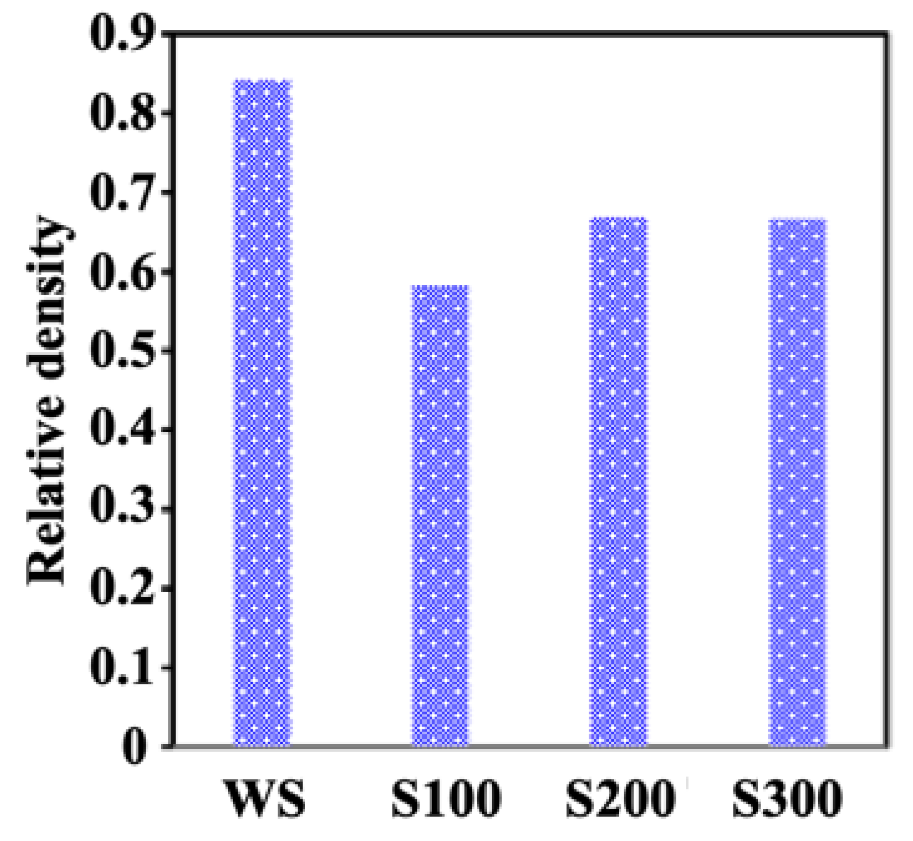
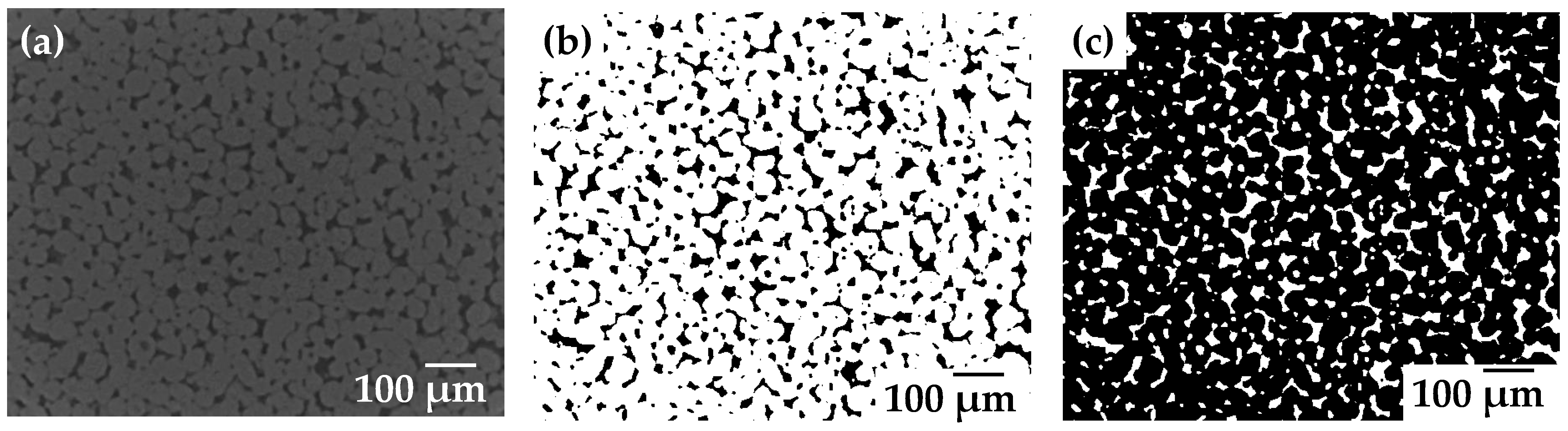
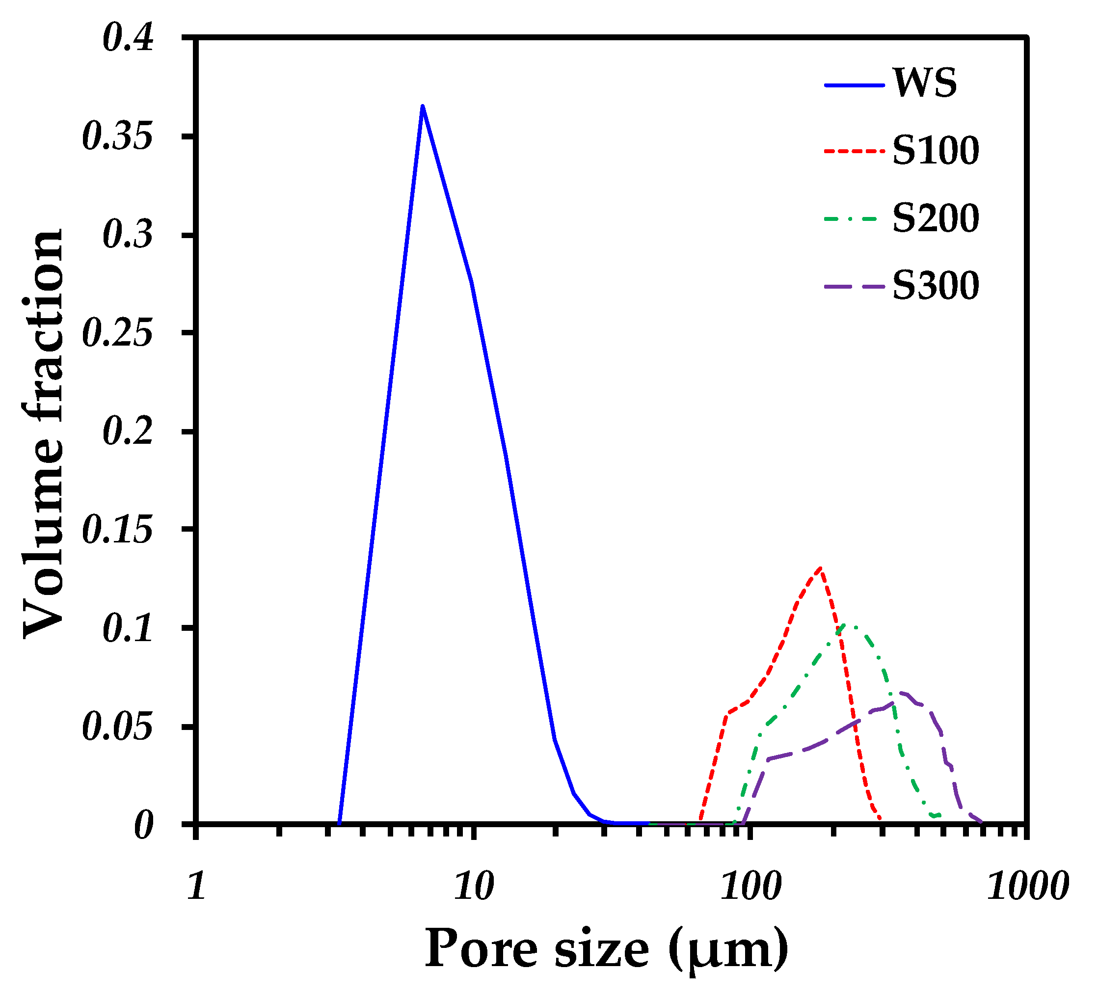
2.2. 3D Image Analysis

To determine the pore characteristics, 3D images of the samples were acquired using computed microtomography (MCT). Figure 3a–d shows 2D virtual slices of the initial images. In order to analyze the porosity of the sample without pore formers, a resolution of 1 µm voxel size was used (Figure 3a), which allows us to observe and measure the interparticle pores left after the sintering process. Conversely, for studying the larger pores created by the pore formers, a resolution of 8 µm voxel size was used to observe the whole sample (Figure 3b–d). In order to eliminate the border issues, an inner volume is virtually cropped from the initial images, as illustrated by the rectangle in Figure 3a–d. The volume used to analyze the samples was 500 × 500 × 500 voxels, representing a volume of 0.125 mm3 for the WS pore formers and 64 mm3 for samples with pore formers; the 3D rendering of the four samples is shown in Figure 3e–h to illustrate the distribution of pores.
The quality of the 3D images after reconstruction was good since the empty space is clearly distinguished from the solid part, i.e., the 316L particles, see Figure 3a–d. However, the contrast between the solid and porous phases was improved using filters in the Image J IJ 1.46r software. Both unsharp masks and median filters were used to enhance the contrast between solid and void phases. For example, a virtual slice of the WS electrode after the filtering process is shown in Figure 4a. To allow the analysis of the porosity, thresholding to distinguish the solid and pore phases is performed based on the gray-level histogram. Next, different morphological operations, like opening, closing, and erosion, were achieved to improve the quality of the binary images. Figure 4b shows the binary image of 316L SS particles in white and pores in black. The binary image is then inverted to obtain information on the porosity, as shown in Figure 4c.
Quantitative data of the porosity can be extracted from the binary images; for this case, the pore volume fraction is calculated by dividing the number of voxels corresponding to the pore phase by the total number of voxels in the image. The pore size distribution is estimated from the pore binary images by measuring the pore volume englobed in an octahedral structural element, which starts with a size of 2 voxels per side and increases at each step. Previous authors have used this methodology to determine the distribution of pores when porosity is interconnected for both metallic and ceramic foams [38]. Pore interconnectivity was determined by following the methodology proposed by Olmos et al. [34,39]. The specific surface was estimated using the module contained in the Avizo® software (V9.0).
The pore size distribution of the samples with and without pore formers is plotted in Figure 5. It is found that interparticle pore sizes ranged between 4 to 30 µm, lower than the initial particle sizes. The median pore size (d50) is around 8 µm, see Table 1, which is around a third of the median particle size. Adding pore formers increases the pore sizes to 80 µm or above because the voxel size image resolution used in this kind of sample cannot detect the interparticle pores. However, it is expected that the solid structure of the samples fabricated with pore formers have similar interparticle pore sizes. Nevertheless, those kinds of pores cannot be taken into account because it is assumed that liquid will pass preferably through the largest pores that bring easier flow paths. As expected, the pore size distribution of samples increased as the size of the pore formers increased. The d50 of pores increased from 114 to 333 µm by increasing the particle size distribution of pore formers from S100 to S300, suggesting that large pores remain in the particle size range used to create them.
Most pores are connected in 3D since the pore connectivity gives values of 90% and higher, see Table 1. It is also noticed that connectivity improved with increasing pore volume fraction since the WS sample shows lower connectivity. To illustrate the pore connectivity, Figure 6a,b show a 3D rendering of the porosity inside the sample, and pseudo-colors are used to identify interconnected pores. It can be noticed that large pores are fully interconnected, while interparticle pores have more disconnected pores, which is due to the densification during sintering. It should be pointed out that pore former particles were randomly distributed inside the sample because particle agglomerates cannot be observed in Figure 6b.

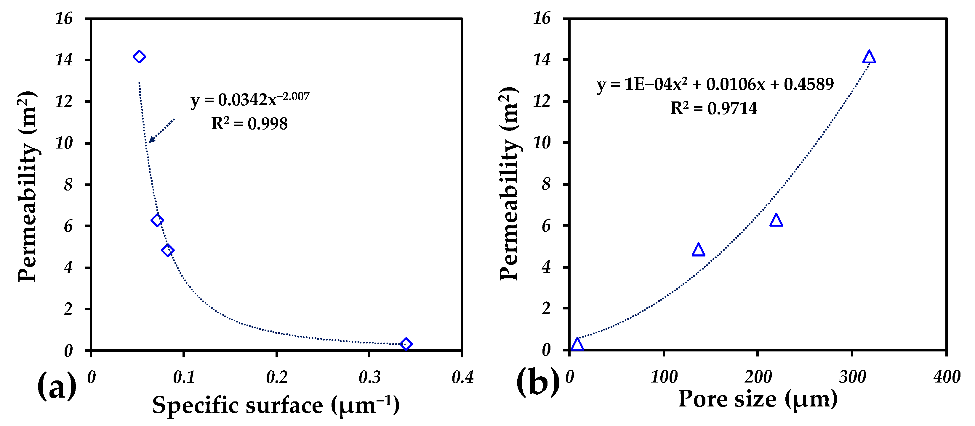
2.3. Permeability Analysis

Permeability simulations were carried out on the 3D images with the aid of Avizo software® (V9.0) by considering water viscosity at room temperature. Numerical simulations are performed by solving the Navier–Stokes equations in a laminar regime; more details about the numerical simulations can be found elsewhere [40]. Figure 6c,d show the simulated flow patterns through the samples WS sample and S300, respectively. The flow paths are completely different; for the sample without pore formers, the flow passes for the whole sample with many tortuous paths. Conversely, the samples fabricated with pore formers (S100, S200, and S300) mainly show a few paths concentrated in the middle of the sample, which indicates that the connection between pores plays an important role in permeability processes. The color code of the streamlines indicates the velocity of the fluid at any point in the 3D image, being highest for red and lowest for blue. It can be seen that the velocity undergoes more changes in the WS sample, which is mainly associated with the tortuosity of the path because the interparticle porosity is more complex than that obtained when pore formers are used.
The permeability values for all samples are listed in Table 1. It was found that adding pore formers improves permeability. To evaluate the characteristics of porosity that have a greater influence, the permeability values are plotted as a function of the specific surface and median pore size in Figure 7a and Figure 7b, respectively. It is found that permeability is highly reduced as the specific surface increases; a power law can be used to describe the effect of the specific surface on the permeability, as can be seen in Figure 7a. It was estimated that the specific surface diminishes as the particle size of the pore formers increases, which is consistent with the concept that “the specific surface area increases with decreasing particle size”. The maximum reduction in specific surface area is around ten times that seen in the WS sample.
The effect of pore size indicates that permeability increases quadratically as the median pore increases. The values indicate that permeability is improved around ten times for the sample fabricated with the larger pore formers compared to the WS sample.

2.4. Linear Sweep Voltammetry Analysis

Figure 8a shows the cathodic branch of the η–I (overpotential–cathodic current density) curves obtained from the linear sweep voltammetry (LSV) tests used to determine the catalytic activity in the HER in a NaOH medium at a concentration of 0.5 M. It is shown that to generate a current density of 50 mA/cm2 [1,41,42], the S100 and S300 electrodes presented a cathodic overpotential of around −0.64 V, this value being lower than those of the WS and S200 electrodes, which presented values of about −0.68 and −0.71 V, respectively. It is important to note that the electrodes display a similar catalytic behavior at this concentration, and according to some studies, the high Ni content in 316L SS increases its intrinsic electrocatalytic activity [43,44]; at the same time, the porous systems increase the electrocatalytic area as observed in the study by Shervedani [45], who concluded that the increase in surface roughness increases the catalytic activity of porous electrodes by 30%. Conversely, analyzing the η–I curves corresponding to sintered 316L SS with induced porosity evaluated at a concentration of 1.5 M NaOH (Figure 8b), it is observed that the cathodic overpotential obtained at a current density of 50 mA/cm2 is reduced compared to that seen in a low concentration of alkaline medium, indicating that the increase in the concentration induces a better HER activity [46,47]. The values obtained for hydrogen production overpotential were −0.37 V for the S100 and S200 electrodes, the best catalytic performance. Furthermore, the overpotential values obtained for WS and S300 were −0.45 and −0.57 V, respectively. In general terms, as the particle formers reduce in size, the specific surface area increases, for this reason, the reduction in pore size increases the catalytic activity of 316L SS by approximately 35% at high concentrations. Conversely, at low concentrations, the variation in the overpotential of all samples is less than 10%, which does not represent a significant variation in the porous size effect. This could be caused by a lower cathodic reaction rate compared to at the higher concentration that causes saturation of the catalytic active sites [48]. This could cause the S300 electrode to show lower catalytic activity, due to its lower specific active area and lower number of active sites for HER.

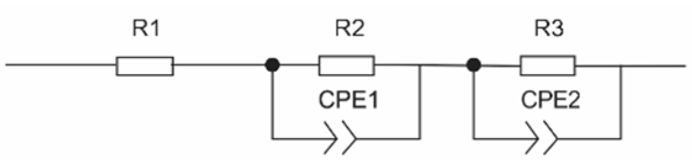
2.5. Electrochemical Impedance Spectroscopy Analysis

In order to evaluate the behavior of the electrode/electrolyte interface and the electrocatalytic activity of the different porosities evaluated, the HER was investigated using the EIS technique. In Figure 9a, the impedance spectra of porous 316L SS are shown in WS sintered conditions and with different pore sizes (S100, S200, and S300 samples) evaluated in a solution of 0.5 M NaOH. A semicircle at high frequencies is observed in the Nyquist plot of the WS electrode caused by a charge transfer mechanism. Conversely, at low frequencies, it is observed that there is a tendency to form a line with an angle of 45° related to a diffusion of the ions (OH) diluted in the electrolyte toward the interior of the pores. The sintered samples using pore formers of different sizes showed an incomplete semicircle related to a charge transfer mechanism [49,50]. In Figure 9b, the condition that presented a greater magnitude of electrochemical impedance was the S300 electrode, indicative of more excellent resistance to corrosion in an alkaline medium (Figure 9b). However, this means a lower charge transfer for HER [51,52]. Conversely, the electrodes that presented a lower impedance value were the WS and S100 electrodes, presenting a lower resistance to corrosion but higher charge transfer. This effect is caused by a more significant increase in the area caused by the induced porosity, which produces a lower electrocatalytic activity for HER and a higher corrosion resistance.
Figure 9d shows the impedance spectra of the porous electrodes evaluated in a 1.5 M NaOH solution. A similar behavior was observed to that seen with samples tested at lower concentration solution; the WS electrode showed a degradation mechanism controlled by charge transfer and diffusion of species (Figure 9c), related to anodic dissolution and diffusion of hydroxyl ion species (OH) diluted in the electrolyte towards the interior of the pores [53]. The S100, S200, and S300 electrodes showed similar behavior with small semicircles caused by the charge transfer mechanism. In addition, these samples showed a higher impedance magnitude, indicating that their corrosion resistance is better than the condition without pore formers (Figure 9e); this behavior could be related to the pore volume fraction and, accordingly, the specific area, as specific area increases with pore volume. Furthermore, as observed in the LSV at a fixed concentration, lower porous volume induces a reduced overpotential that enhances the catalytic activity of the electrodes [54].
In order to determine the physical behavior and the catalytic activity at the electrode surface, the EIS experimental data were modeled to obtain an electrochemical equivalent circuit (EEC). In the literature, different equivalent circuits for porous systems alloy electrodes have been studied to explain the AC impedance in HER [55,56]. The fit was made using an EEC with two time constants in series (Figure 10) because it is the most suitable for describing the HER response for porous systems. This EEC showed an adequate agreement between the experimental and theoretical data and is made up of a resistive element that represents the resistance to the solution between the working electrode and the reference electrode (R1); at low frequencies, the process is related to the hydrogen evolution reaction, while at high frequencies is related to the porosity. Both processes are represented in the EEC as CPE1-R2 and CPE2-R3, respectively [57,58,59,60,61].
Another essential factor to consider in determining the catalytic activity of the electrodes is the capacitance of the double layer (Cdl) from which the roughness factor (Rf) can be determined, which is a parameter directly proportional to the actual surface area of the electrode due to the absorbed hydrogen. The Cdl value can be calculated using the equation proposed by Brug et al. [61,62]:
C d l = C P E R S 1 + R C T 1 1 C P E 1 φ
As shown in Table 2, the C d l values obtained were higher for the S100 electrode compared to those obtained for the other size particles in both test concentrations, indicating that the electrochemically active area in these electrodes is greater. Conversely, the Rf parameter was determined as shown below by comparing the C d l value obtained from the modeling of the equivalent circuit with the average C d l reference value for metallic electrodes with a smooth surface, which presents a value of 20 µF cm−2 [63,64,65]:
R f = C d l 20   μ F   cm 2
It is important to note that the electrode that showed the highest Cdl and Rf at a concentration of 0.5 M was S100 with 212.03 µF/cm2 and 10.60, respectively. This represents 84% more catalytic activity than the sample without pore formers (WS), which showed lower values of Cdl and Rf. Conversely, an increase in concentration (1.5 M) in the same sample, S100, showed higher Cdl and Rf values of about 234.95 µF/cm2 and 11.74, respectively. These values represent a 48% increase in catalytic activity compared to the S300 electrode, which showed the lowest catalytic activity. Bo Xu et al. [66] concluded that a higher capacitance confirms a relatively large area due to a faster electron transfer rate in the HER [51].

3. Experimental Method

3.1. Sintering 316L Stainless Steels

Spherical powders of 316L SS with a particle size distribution between 45 and 38 μm and ammonium bicarbonate ((NH4)HCO3) salt particles with irregular shapes and a particle size distribution between 100 and 500 µm were used as a matrix and space holders, respectively. In order to create samples with different pore sizes, the salt particles were sieved in 3 ranges: 100–200 μm (S100), 200–300 μm (S200), and 300–400 μm (S300). Samples without salts (WS) and 30 vol.% of salt particles were fabricated by dry mixing in a turbula for 30 min. Then, the powders were poured into an 8 mm die and were compacted in an Instron 1195 series universal testing machine at 450 MPa. After that, salt particles were eliminated in a cylindrical furnace at 180 °C for six hours under high-purity Argon as reported previously [37,39]. Next, all samples were sintered at 1260 °C, heating at 25 °C/min with a dwell time of 1 h monitored using a vertical dilatometer LINSEIS L75V. In order to determine the pore characteristics, 3D images of the sintered samples were acquired by computed microtomography (CMT) with a Zeiss Xradia 510 Versa 3D X-ray microscope (Zeiss, Jena, Germany). The beam intensity was set at 120 kV, and two different voxel sizes were used: 1 µm for samples without salts and 8 µm for samples with salt particles.

3.2. Electrochemical Analysis

Electrochemical tests were performed using a standard electrochemical cell to evaluate the HER. The sintered samples of porous 316L SS were used as a working electrode (WE), a platinum mesh was used as a counter electrode (CE), and a saturated calomel electrode (SCE) was used as a reference electrode (RE). To determine the cathodic overpotential, linear sweep voltammetry (LSV) was carried out in a range potential of −2.0 up to 2.0 V at a scanning rate of about 10 mV/s, and electrochemical impedance spectroscopy (EIS) was used, applying a sine signal in a range frequency of 10−2 a 105 Hz and 10 mV of amplitude, to determine the mechanism involve in HER and the effect of surface roughness and porous size of the electrodes. A CorrTest CS350 potentiostatic (Wuhan Corrtest Instruments Corp., Ltd., Wuhan, China) was used, and tests were conducted in 0.5 M and 1.5 M of NaOH at room temperature.

4. Conclusions

  • The increased NaOH concentration reduces the overpotential for HER, indicating a higher catalytic activity on porous electrodes.
  • The S100 and S200 electrodes in 1.5 M NaOH showed a reduction in overpotential caused by an increase in the active area due to an increment in porous size; however, the S300 electrode, with the largest pores, showed a slightly increased overpotential.
  • The S300 sample showed a higher impedance magnitude, indicating a higher corrosion resistance; however, a low charge transfer reduced the catalytic activity of HER.
  • The S100 and WS electrodes showed a lower impedance magnitude, indicating a lower corrosion resistance; however, high charge transfer increased the catalytic activity of HER.
  • The sample that showed higher Cdl and Rf values was S100, which means a higher active area favoring the HER.

Author Contributions

V.M.S.: conceptualization, formal analysis, investigation, writing—original draft. L.O.: conceptualization, writing—original draft, methodology and validation. M.V.-P.: formal analysis, writing—original draft. H.J.V.-H.: project administration, resources, supervision, and writing—review and editing. J.C.V.: supervision, writing—review and editing. J.M.S.L.: investigation and validation. M.M.M.L.: supervision and validation. All authors have read and agreed to the published version of the manuscript.

Funding

This research was funded by The Consejo Nacional de Humanidades Ciencias y Tecnologías (CONAHCyT) via its support for Victor Manuel Solorio García, Grant IDs 760947 and 474856. Additional funding was provided by the TecNM National Laboratory for Promoting R&D&I in Engineering, led by Héctor Javier Vergara Hernández.

Data Availability Statement

The manuscript “Investigation of Pore Size on the Hydrogen Evolution Reaction of 316L Stainless Steel Porous Electrodes” is an original work and has not been sent elsewhere. All the results are part of the research of the doctoral student Victor Manuel Solorio. These data will be the basis for future works in the author’s field of research.

Acknowledgments

The authors would like to thank CONACYT for its support in preparing Victor Manuel Solorio García studies. They also want to thank the technical support provided by Dante Arteaga in the acquisition and processing of 3D images and the TecNM National Laboratory for Promoting R&D&I in Engineering.

Conflicts of Interest

The authors declare no conflicts of interest.

References

  1. Ďurovič, M.; Hnát, J.; Bouzek, K. Electrocatalysts for the Hydrogen Evolution Reaction in Alkaline and Neutral Media. A Comparative Review. J. Power Sources 2021, 493, 229708. [Google Scholar] [CrossRef]
  2. Pletcher, D.; Li, X. Prospects for Alkaline Zero Gap Water Electrolysers for Hydrogen Production. Int. J. Hydrogen Energy 2011, 36, 15089–15104. [Google Scholar] [CrossRef]
  3. Safizadeh, F.; Ghali, E.; Houlachi, G. Electrocatalysis Developments for Hydrogen Evolution Reaction in Alkaline Solutions—A Review. Int. J. Hydrogen Energy 2015, 40, 256–274. [Google Scholar] [CrossRef]
  4. Shiva Kumar, S.; Lim, H. An Overview of Water Electrolysis Technologies for Green Hydrogen Production. Energy Rep. 2022, 8, 13793–13813. [Google Scholar] [CrossRef]
  5. Xie, J.; Wang, F.; Zhou, Y.; Dong, Y.; Chai, Y.; Dong, B. Internal Polarization Field Induced Hydroxyl Spillover Effect for Industrial Water Splitting Electrolyzers. Nanomicro Lett. 2024, 16, 39. [Google Scholar] [CrossRef]
  6. Marini, S.; Salvi, P.; Nelli, P.; Pesenti, R.; Villa, M.; Kiros, Y. Stable and Inexpensive Electrodes for the Hydrogen Evolution Reaction. Int. J. Hydrogen Energy 2013, 38, 11484–11495. [Google Scholar] [CrossRef]
  7. Gao, W.K.; Yang, M.; Chi, J.Q.; Zhang, X.Y.; Xie, J.Y.; Guo, B.Y.; Wang, L.; Chai, Y.M.; Dong, B. In Situ Construction of Surface Defects of Carbon-Doped Ternary Cobalt-Nickel-Iron Phosphide Nanocubes for Efficient Overall Water Splitting. Sci. China Mater. 2019, 9, 1285–1296. [Google Scholar] [CrossRef]
  8. Laleh, M.; Hughes, A.E.; Xu, W.; Cizek, P.; Tan, M.Y. Unanticipated Drastic Decline in Pitting Corrosion Resistance of Additively Manufactured 316L Stainless Steel after High-Temperature Post-Processing. Corros. Sci. 2020, 165, 108412. [Google Scholar] [CrossRef]
  9. Yu, F.; Li, F.; Sun, L. Stainless Steel as an Efficient Electrocatalyst for Water Oxidation in Alkaline Solution. Int. J. Hydrogen Energy 2016, 41, 5230–5233. [Google Scholar] [CrossRef]
  10. Alhakemy, A.Z.; Ahmed Amine Nassr, A.B.; Kashyout, A.E.H.; Wen, Z. Modifying the 316L Stainless Steel Surface by an Electrodeposition Technique: Towards High-Performance Electrodes for Alkaline Water Electrolysis. Sustain. Energy Fuels 2022, 6, 1382–1397. [Google Scholar] [CrossRef]
  11. Cabo Rios, A.; Hryha, E.; Olevsky, E.; Harlin, P. Sintering Anisotropy of Binder Jetted 316L Stainless Steel: Part I–Sintering Anisotropy. Powder Metall. 2022, 65, 273–282. [Google Scholar] [CrossRef]
  12. Garibay-Coria, S.; Velasco-Plascencia, M.; Villalobos, J.C.; Vázquez-Gómez, O.; Molina-Ocampo, A.; Vergara-Hernández, H.J. Chromium Effect Over the Hydrogen Evolution Reaction and Corrosion Behavior on Ni-Cr Porous Electrodes. J. Mater. Eng. Perform. 2024, 1–11. [Google Scholar] [CrossRef]
  13. Velasco-Plascencia, M.; Vázquez-Gómez, O.; Olmos, L.; Reyes-Calderón, F.; Vergara-Hernández, H.J.; Villalobos, J.C. Determination of Activation Energy on Hydrogen Evolution Reaction for Nickel-Based Porous Electrodes during Alkaline Electrolysis. Catalysts 2023, 13, 517. [Google Scholar] [CrossRef]
  14. Kan, X.; Yang, D.; Zhao, Z.; Sun, J. 316L FFF Binder Development and Debinding Optimization. Mater. Res. Express 2021, 8, 116515. [Google Scholar] [CrossRef]
  15. Larimian, T.; Kannan, M.; Grzesiak, D.; AlMangour, B.; Borkar, T. Effect of Energy Density and Scanning Strategy on Densification, Microstructure and Mechanical Properties of 316L Stainless Steel Processed via Selective Laser Melting. Mater. Sci. Eng. A 2020, 770, 138455. [Google Scholar] [CrossRef]
  16. Jamalkhani, M.; Dorula, M.; Roberts, E.; Mostafaei, A. Densification Kinetics, Microstructural Evolution and Mechanical Properties of Isothermally Sintered Binder Jetted 316L Stainless Steel. J. Manuf. Process 2024, 125, 267–282. [Google Scholar] [CrossRef]
  17. Nagaraju, K.V.V.; Kumaran, S.; Srinivasa Rao, T. Microwave Sintering of 316L Stainless Steel: Influence of Sintering Temperature and Time. Mater. Today Proc. 2020, 27, 2066–2071. [Google Scholar] [CrossRef]
  18. Chadha, K.; Tian, Y.; Spray, J.G.; Aranas, C. Effect of Annealing Heat Treatment on the Microstructural Evolution and Mechanical Properties of Hot Isostatic Pressed 316L Stainless Steel Fabricated by Laser Powder Bed Fusion. Metals 2020, 10, 753. [Google Scholar] [CrossRef]
  19. Tanvir, G.; Karim, M.A.; Jadhav, S.; Islam, S.; Kim, Y.M.; Ryu, H.J.; Kim, D.B. Effect of Hot Isostatic Pressing on Porosity of Wire-Arc Directed Energy Deposited TZM/NbZr1 Bimetallic Structure. Virtual Phys. Prototyp. 2024, 19, e2404989. [Google Scholar] [CrossRef]
  20. Ji, S.; Liu, Z.; Wang, G.; Liu, Y.; Jing, Y. Effects of Sintering Temperature and Particle Size on Permeability of Functionally Gradient Composite Porous Materials Prepared by Hanging Slurry Process. SN Appl. Sci. 2020, 2, 1–20. [Google Scholar] [CrossRef]
  21. Jain, H.; Mondal, D.P.; Gupta, G.; Kumar, R.; Singh, S. Synthesis and Characterization of 316L Stainless Steel Foam Made through Two Different Removal Process of Space Holder Method. Manuf. Lett. 2020, 26, 33–36. [Google Scholar] [CrossRef]
  22. Jain, H.; Mondal, D.P.; Gupta, G.; Kumar, R. Effect of Compressive Strain Rate on the Deformation Behaviour of Austenitic Stainless Steel Foam Produced by Space Holder Technique. Mater. Chem. Phys. 2021, 259, 124010. [Google Scholar] [CrossRef]
  23. Lecis, N.; Mariani, M.; Beltrami, R.; Emanuelli, L.; Casati, R.; Vedani, M.; Molinari, A. Effects of Process Parameters, Debinding and Sintering on the Microstructure of 316L Stainless Steel Produced by Binder Jetting. Mater. Sci. Eng. A 2021, 828, 142108. [Google Scholar] [CrossRef]
  24. Yusuf, S.M.; Chen, Y.; Boardman, R.; Yang, S.; Gao, N. Investigation on Porosity and Microhardness of 316L Stainless Steel Fabricated by Selective Laser Melting. Metals 2017, 7, 64. [Google Scholar] [CrossRef]
  25. Jain, H.; Gupta, G.; Mondal, D.P.; Srivastava, A.K.; Pandey, A.; Srivastava, S.K.; Kumar, R. Effect of Particle Shape on Microstructure and Compressive Response of 316L SS Foam by Space Holder Technique. Mater. Chem. Phys. 2021, 271, 124924. [Google Scholar] [CrossRef]
  26. Meenashisundaram, G.K.; Xu, Z.; Nai, M.L.S.; Lu, S.; Ten, J.S.; Wei, J. Binder Jetting Additive Manufacturing of High Porosity 316L Stainless Steel Metal Foams. Materials 2020, 13, 3744. [Google Scholar] [CrossRef]
  27. Zhang, G.; Qu, Z.; Tao, W.Q.; Wang, X.; Wu, L.; Wu, S.; Xie, X.; Tongsh, C.; Huo, W.; Bao, Z.; et al. Porous Flow Field for Next-Generation Proton Exchange Membrane Fuel Cells: Materials, Characterization, Design, and Challenges. Chem. Rev. 2023, 123, 989–1039. [Google Scholar] [CrossRef] [PubMed]
  28. Lu, X.; Zhao, Y.; Zhang, Y.; Wu, M. Numerical Study on Fluid Flow Behavior and Heat Transfer Performance of Porous Media Manufactured by a Space Holder Method. Materials 2024, 17, 2695. [Google Scholar] [CrossRef] [PubMed]
  29. Yun, S.J.; Kim, H.J.; Seo, E.C.; Kim, M.J.; Park, M.; Lee, J.; Yun, J.Y. Fabrication of a Plate-Type Porous Stainless Steel 316l Powder Filter with Different Pore Structures without Use of a Binder. Arch. Metall. Mater. 2024, 69, 497–500. [Google Scholar] [CrossRef]
  30. Kale, A.B.; Kim, B.K.; Kim, D.I.; Castle, E.G.; Reece, M.; Choi, S.H. An Investigation of the Corrosion Behavior of 316L Stainless Steel Fabricated by SLM and SPS Techniques. Mater. Charact. 2020, 163, 110204. [Google Scholar] [CrossRef]
  31. Zhang, C.; Yuan, Y.; Shi, C.; Chen, J. Material Extrusion-Based Fabrication of 316L Stainless Steel: Analysis of Debinding and Sintering, Mechanical Properties, and Corrosion Resistance. Int. J. Adv. Manuf. Technol. 2023, 129, 587–599. [Google Scholar] [CrossRef]
  32. Okonkwo, P.C.; Barhoumi, E.M.; Mansir, I.B.; Emori, W.; Bhowmik, H. Effect of Electrode Material on the Hydrogen Production Using a Low-Cost Home-Made Alkaline Electrolyzer. Vacuum 2022, 198, 110878. [Google Scholar] [CrossRef]
  33. Liu, J.; Gao, Y.; Fan, Y.; Zhou, W. Fabrication of Porous Metal by Selective Laser Melting as Catalyst Support for Hydrogen Production Microreactor. Int. J. Hydrogen Energy 2020, 45, 10–22. [Google Scholar] [CrossRef]
  34. Olmos, L.; Bouvard, D.; Salvo, L.; Bellet, D.; Di Michiel, M. Characterization of the Swelling during Sintering of Uniaxially Pressed Copper Powders by in Situ X-Ray Microtomography. J. Mater. Sci. 2014, 49, 4225–4235. [Google Scholar] [CrossRef]
  35. Manière, C.; Saccardo, E.; Lee, G.; McKittrick, J.; Molinari, A.; Olevsky, E.A. Swelling Negation during Sintering of Sterling Silver: An Experimental and Theoretical Approach. Results Phys. 2018, 11, 79–84. [Google Scholar] [CrossRef]
  36. Biguereau, E.; Bouvard, D.; Chaix, J.M.; Roure, S. On the Swelling of Silver Powder during Sintering. Powder Metall. 2016, 59, 394–400. [Google Scholar] [CrossRef]
  37. Cabezas-Villa, J.L.; Olmos, L.; Bouvard, D.; Lemus-Ruiz, J.; Jiménez, O. Processing and Properties of Highly Porous Ti6Al4V Mimicking Human Bones. J. Mater. Res. 2018, 33, 650–661. [Google Scholar] [CrossRef]
  38. Lin, C.L.; Miller, J.D. 3D Characterization and Analysis of Particle Shape Using X-Ray Microtomography (XMT). Powder Technol. 2005, 154, 61–69. [Google Scholar] [CrossRef]
  39. Olmos, L.; Bouvard, D.; Cabezas-Villa, J.L.; Lemus-Ruiz, J.; Jiménez, O.; Arteaga, D. Analysis of Compression and Permeability Behavior of Porous Ti6Al4V by Computed Microtomography. Met. Mater. Int. 2019, 25, 669–682. [Google Scholar] [CrossRef]
  40. Callow, B.; Falcon-Suarez, I.; Marin-Moreno, H.; Bull, J.M.; Ahmed, S. Optimal X-Ray Micro-CT Image Based Methods for Porosity and Permeability Quantification in Heterogeneous Sandstones. Geophys. J. Int. 2020, 223, 1210–1229. [Google Scholar] [CrossRef]
  41. Zeng, M.; Li, Y. Recent Advances in Heterogeneous Electrocatalysts for the Hydrogen Evolution Reaction. J. Mater. Chem. A Mater. 2015, 3, 14942–14962. [Google Scholar] [CrossRef]
  42. Fu, H.Q.; Zhou, M.; Liu, P.F.; Liu, P.; Yin, H.; Sun, K.Z.; Yang, H.G.; Al-Mamun, M.; Hu, P.; Wang, H.F.; et al. Hydrogen Spillover-Bridged Volmer/Tafel Processes Enabling Ampere-Level Current Density Alkaline Hydrogen Evolution Reaction under Low Overpotential. J. Am. Chem. Soc. 2022, 144, 6028–6039. [Google Scholar] [CrossRef]
  43. Takaki, S.; Nanba, S.; Imakawa, K.; Macadre, A.; Yamabe, J.; Matsunaga, H.; Matsuoka, S. Determination of Hydrogen Compatibility for Solution-Treated Austenitic Stainless Steels Based on a Newly Proposed Nickel-Equivalent Equation. Int. J. Hydrogen Energy 2016, 41, 15095–15100. [Google Scholar] [CrossRef]
  44. Liu, M.; Li, H.; Liu, S.; Wang, L.; Xie, L.; Zhuang, Z.; Sun, C.; Wang, J.; Tang, M.; Sun, S.; et al. Tailoring Activation Sites of Metastable Distorted 1T′-Phase MoS2 by Ni Doping for Enhanced Hydrogen Evolution. Nano Res. 2022, 15, 5946–5952. [Google Scholar] [CrossRef]
  45. Shervedani, R.K.; Alinoori, A.H.; Madram, A.R. Electrocatalytic Activities of Nickel-Phosphorous Composite Coating Reinforced with Codeposited Graphite Carbon for Hydrogen Evolution Reaction in Alkaline Solution. J. New Mater. Electrochem. Syst. 2008, 11, 259–265. [Google Scholar]
  46. Olivares-Ramírez, J.M.; Campos-Cornelio, M.L.; Uribe Godínez, J.; Borja-Arco, E.; Castellanos, R.H. Studies on the Hydrogen Evolution Reaction on Different Stainless Steels. Int. J. Hydrogen Energy 2007, 32, 3170–3173. [Google Scholar] [CrossRef]
  47. Yin, H.; Rong, F.; Xie, Y. A Review of Typical Transition Metal Phosphides Electrocatalysts for Hydrogen Evolution Reaction. Int. J. Hydrogen Energy 2024, 52, 350–375. [Google Scholar] [CrossRef]
  48. Argyle, M.D.; Bartholomew, C.H. Heterogeneous Catalysts Deactivation and Regeneration: A Review. Catalysts 2015, 5, 145–269. [Google Scholar] [CrossRef]
  49. Gomez, M.J.; Franceschini, E.A.; Lacconi, G.I. Ni and NixCoy Alloys Electrodeposited on Stainless Steel AISI 316L for Hydrogen Evolution Reaction. Electrocatalysis 2018, 9, 459–470. [Google Scholar] [CrossRef]
  50. Zhang, Y.; Pan, J.; Gong, G.; Song, R.; Yuan, Y.; Li, M.; Hu, W.; Fan, P.; Yuan, L.; Wang, L. In Situ Surface Reconstruction of Catalysts for Enhanced Hydrogen Evolution. Catalysts 2023, 13, 120. [Google Scholar] [CrossRef]
  51. Łosiewicz, B.; Budniok, A.; Rówiński, E.; Łagiewka, E.; Lasia, A. The Structure, Morphology and Electrochemical Impedance Study of the Hydrogen Evolution Reaction on the Modified Nickel Electrodes. Int. J. Hydrogen Energy 2004, 29, 145–157. [Google Scholar] [CrossRef]
  52. Tang, J.; Xu, J.L.; Li, L.L.; Ma, Y.C.; Ye, Z.G.; Luo, H.Y.; Luo, J.M. In-Situ Hydrothermal Synthesis of Ni–MoO2 Heterostructure on Porous Bulk NiMo Alloy for Efficient Hydrogen Evolution Reaction. Trans. Nonferrous Met. Soc. China 2022, 32, 1598–1608. [Google Scholar] [CrossRef]
  53. Xu, J.L.; Li, L.L.; Tang, J.; Dai, L.; Li, X.B.; Ye, Z.G.; Luo, J.M. Powder Metallurgy Synthesis of Porous NiMo Alloys as Efficient Electrocatalysts to Enhance the Hydrogen Evolution Reaction. J. Alloys Compd. 2021, 865, 158901. [Google Scholar] [CrossRef]
  54. Vesborg, P.C.K.; Seger, B.; Chorkendorff, I. Recent Development in Hydrogen Evolution Reaction Catalysts and Their Practical Implementation. J. Phys. Chem. Lett. 2015, 6, 951–957. [Google Scholar] [CrossRef] [PubMed]
  55. Hitz, C.; Lasia, A. Experimental Study and Modeling of Impedance of the Her on Porous Ni Electrodes. J. Electroanal. Chem. 2001, 500, 213–222. [Google Scholar] [CrossRef]
  56. Navarro-Flores, E.; Chong, Z.; Omanovic, S. Characterization of Ni, NiMo, NiW and NiFe Electroactive Coatings as Electrocatalysts for Hydrogen Evolution in an Acidic Medium. J. Mol. Catal. A Chem. 2005, 226, 179–197. [Google Scholar] [CrossRef]
  57. Wu, L.; Guo, X.; Xu, Y.; Xiao, Y.; Qian, J.; Xu, Y.; Guan, Z.; He, Y.; Zeng, Y. Electrocatalytic Activity of Porous Ni–Fe–Mo–C–LaNi 5 Sintered Electrodes for Hydrogen Evolution Reaction in Alkaline Solution. RSC Adv. 2017, 7, 32264–32274. [Google Scholar] [CrossRef]
  58. Metikoš-Huković, M.; Jukić, A. Correlation of Electronic Structure and Catalytic Activity of Zr–Ni Amorphous Alloys for the Hydrogen Evolution Reaction. Electrochim. Acta 2000, 45, 4159–4170. [Google Scholar] [CrossRef]
  59. Kramer, M.; Tomkiewicz, M. Porous Electrodes: I. Numerical Simulation Using. Random Network and Single-Pore Models. J. Electrochem. Soc. 1984, 131, 1283. [Google Scholar] [CrossRef]
  60. Navarro-Flores, E.; Omanovic, S. Hydrogen Evolution on Nickel Incorporated in Three-Dimensional Conducting Polymer Layers. J. Mol. Catal. A Chem. 2005, 242, 182–194. [Google Scholar] [CrossRef]
  61. Brug, G.J.; van den Eeden, A.L.G.; Sluyters-Rehbach, M.; Sluyters, J.H. The Analysis of Electrode Impedances Complicated by the Presence of a Constant Phase Element. J. Electroanal. Chem. Interfacial Electrochem. 1984, 176, 275–295. [Google Scholar] [CrossRef]
  62. Panek, J.; Serek, A.; Budniok, A.; Rówinski, E.; Łagiewka, E. Ni+Ti Composite Layers as Cathode Materials for Electrolytic Hydrogen Evolution. Int. J. Hydrogen Energy 2003, 28, 169–175. [Google Scholar] [CrossRef]
  63. Solmaz, R.; Döner, A.; Şahin, I.; Yüce, A.O.; Kardaş, G.; Yazici, B.; Erbil, M. The Stability of NiCoZn Electrocatalyst for Hydrogen Evolution Activity in Alkaline Solution during Long-Term Electrolysis. Int. J. Hydrogen Energy 2009, 34, 7910–7918. [Google Scholar] [CrossRef]
  64. Danaee, I.; Noori, S. Kinetics of the Hydrogen Evolution Reaction on NiMn Graphite Modified Electrode. Int. J. Hydrogen Energy 2011, 36, 12102–12111. [Google Scholar] [CrossRef]
  65. Torres, C.; Moreno, B.; Chinarro, E.; de Fraga Malfatti, C. Nickel-Polyaniline Composite Electrodes for Hydrogen Evolution Reaction in Alkaline Media. Int. J. Hydrogen Energy 2017, 42, 20410–20419. [Google Scholar] [CrossRef]
  66. Xu, B.; Chen, Z.; Zhang, H.; Sun, Y.; Li, C. Novel Ni(S0.49Se0.51)2 Porous Flakes Array on Carbon Fiber Cloth for Efficient Hydrogen Evolution Reaction. Int. J. Hydrogen Energy 2017, 42, 30119–30125. [Google Scholar] [CrossRef]
Figure 1. Shrinkage as a function of time and temperature during sintering samples without and with three different particle size distributions of pore formers powders.
Catalysts 15 00038 g001
Figure 2. Sintered density as a function of the particle size distribution of pore formers.
Catalysts 15 00038 g002
Figure 3. 2D virtual slices and 3D rendering of a REV extracted from the center of WS samples fabricated without pore formers (a,e), and with 30% of pore formers with different particle size distributions; (b,f) S100, (c,g) S200, (d,h) S300, respectively. The white rectangle indicates where the inner volume was extracted to make the 3D rendering.
Catalysts 15 00038 g003
Figure 4. 2D virtual slices of the sample without pore formers showing the image processing, (a) initial, binary images of (b) 316L particles, and (c) pores.
Catalysts 15 00038 g004
Figure 5. Pore size distributions of samples without and with pore formers of different sizes.
Catalysts 15 00038 g005
Figure 6. 3D rendering of the porosity after sintering of samples (a) WS and (b) S300 particle; distribution and streamlines for the flow of water through pores in the vertical direction for both samples (c) without and (d) with pore formers particles. The color of the streamlines indicates the flow velocity, being the red the fastest and blue slowest.
Catalysts 15 00038 g006
Figure 7. Permeability estimated from numerical simulations as a function of (a) specific surface and (b) median pore size.
Catalysts 15 00038 g007
Figure 8. HER current density of porous stainless steel as a function of particle size, evaluated with (a) 0.5 M NaOH and (b) 1.5 M NaOH.
Catalysts 15 00038 g008
Figure 9. EIS at 0.5 M NaOH, (a) Nyquist diagram, (b) Bode diagram—impedance magnitude and (c) Bode diagram—phase angle; EIS at 1.5 M NaOH, (d) Nyquist diagram, (e) Bode diagram—impedance magnitude and (f) Bode diagram—phase angle.
Catalysts 15 00038 g009
Figure 10. Electrochemical equivalent circuit used by modeling RCT and Cdl in 316L stainless steel in the different sintering conditions.
Catalysts 15 00038 g010
Table 1. 3D Pore characteristics of samples containing pore formers of different particle sizes.
Sampled50
(µm)
Specific Surface (µm−1)Pore Connectivity (%)Permeability
(µm2)
WS8.190.339564900.2734
S100144.910.0829015982.3083
S200228.520.071612995.5710
S300333.050.0519835999.4606
Table 2. Parameters obtained from electrochemical equivalent circuit.
Cdl (µF/cm2)Rf
Sample0.5 M1.5 M0.5 M1.5 M
WS33.50153.341.677.66
S100212.03234.9510.6011.74
S20039.98155.841.997.79
S30048.17131.702.406.58
Disclaimer/Publisher’s Note: The statements, opinions and data contained in all publications are solely those of the individual author(s) and contributor(s) and not of MDPI and/or the editor(s). MDPI and/or the editor(s) disclaim responsibility for any injury to people or property resulting from any ideas, methods, instructions or products referred to in the content.

