Abstract
Copper and iron-based bimetallic nickel catalysts supported on Mesostructured Silica Nanoparticles (MSNs) with compositions of 50% Ni–5% Cu/MSN and 50% Ni–5% Fe/MSN were prepared using an impregnation method, and they were compared with a monometallic 50% Ni–MSN catalyst for their activity and stability in methane decomposition reaction. The influence of promoters, such as Cu and Fe, at different reaction temperatures (700 °C, 800 °C and 900 °C) was investigated. The results revealed that the Cu and Fe-promoted catalysts significantly increased the hydrogen yield in methane decomposition compared with the unpromoted catalyst. This could be attributed to the formation of Ni–Cu and Ni–Fe bimetallic alloys in the catalysts, respectively, and this favored the stability of the catalysts. With increasing reaction temperature, the hydrogen yield also increased. However, the hydrogen yield and the lifetime of the nickel catalyst were enhanced upon the addition of iron compared to copper at all the reaction temperatures. The analysis conducted over the spent catalysts validated the formation of multi-walled carbon nanotubes with a bamboo-like internal channel over the catalysts along with a high crystallinity and graphitization degree of the carbon produced.
1. Introduction
Global warming, a phenomenon caused by increased human activity, has instigated widespread environmental pollution. The emission of greenhouse gases coming from transportation, industrial and other human activities leads to severe environmental pollution. Therefore, an alternative to fossil fuel as a major source of energy for transportation and stationary applications is needed. Many studies have been conducted to develop alternative sources of renewable energy worldwide [1]. Hydrogen energy is a green energy that can be used in stationary and practical applications [2]. Recently, hydrogen has been applied in the field of transportation and has been used in fuel cell technology [3,4].
Hydrogen can be produced from various sources, such as biomass, water, natural gas and hydrocarbon, via different kinds of available methods [5]. Methane decomposition is a practical method to produce hydrogen directly from methane without producing any greenhouse gas [6]. In contrast to conventional steam reforming, methane decomposition requires no further process to purify the produced hydrogen [7]. A variety of carbon structures, such as carbon nanotubes, graphite and graphene, were produced at the end of the reaction [8]. This graphitic carbon can be further utilized for miscellaneous applications, such as a catalyst for several catalytic processes or in hydrogen storage materials [9,10]. Methane decomposition is a highly endothermic process that requires high temperatures of approximately 1200 °C. The reaction can be represented as
To reduce the reaction temperature, the use of heterogeneous catalysts has been introduced in the reaction. Studies have assessed the use of metal catalysts in methane decomposition [11]. Apart from being low cost, the abundance of transition metals, such as Ni, Cu, Fe and Co, has made them the most used catalyst in methane decomposition [12,13,14,15]. Syed-Muhammad et al. summarized studies on metallic catalysts, promoters, metal loading, operational conditions and feedstock mixtures in methane decomposition [16]. They found that these factors play a crucial role in determining the performance in methane decomposition. Ni catalysts supported over several metal oxides, such as silica, magnesia, zirconia and titania, display optimal performance and higher stability in methane decomposition compared with other monometallic catalysts, such as Co, Cu and Fe [17,18,19]. Hasnan et al. recently found that Ni is the most active metal in methane decomposition [20]. The selection of appropriate catalyst support is crucial in the performance of Ni-based catalysts. Mesoporous silica-based materials are seldom used as catalyst support in methane decomposition, but they are commonly used in other catalytic processes, such as dry reforming [21], CO2 methanation [22] and drug delivery [23]. The outstanding characteristics of mesoporous silica, such as high surface area and porosity, contribute to adequate active sites available for the reaction, and the presence of a large pore size would help in metal dispersion [24,25].
Apart from that, the influence of the catalyst composition in the bimetallic catalyst also plays an important role in determining its catalytic performance [26]. Pudukudy et al. examined the performance of a Ni catalyst regarding Pd addition in the catalytic decomposition of methane [10]. They found that the incorporation of a co-metal improves the hydrogen yield and stability of the Ni catalyst throughout the 420 min of the reaction. Even though only a small amount of Pd is added, the performance of the Ni-based catalyst is still enhanced compared with that of the unpromoted catalyst. This result agrees with the findings of another study by Pudukudy et al. on a monometallic Ni catalyst, in which Ni/SiO2 displayed low stability during 300 min of reaction [27]. Saraswat and Pant reported a Ni-based bimetallic catalyst in the catalytic decomposition of methane using Cu and Zn as promoters supported over Ni/MCM-22 [28]. They found that the presence of Cu and Zn prevents nanoparticle agglomeration and enhances the metal dispersion on the catalyst support, thus contributing to the high catalytic performance in methane decomposition. Hence, many studies focused on bimetallic catalysts to develop Ni-based catalysts with improved activity in methane decomposition [29,30,31,32,33].
Cu and Fe are metals commonly studied as promoters in the methane decomposition process. Cunha et al. reported that the formation of a Ni–Cu alloy promotes catalyst stability during the reaction [34]. The addition of Cu inhibited the development of encapsulating carbon, owing to the formation of a Ni–Cu alloy, which segregated the Ni active sites, complicating the reaction of the adsorbed carbon species with each other on the catalyst surface. This result agrees with the findings of Awad et al. [29]. In another study, Bayat et al. examined the activity of a Ni–Fe/Al2O3 catalyst in methane decomposition and noticed that the introduction of Fe improves the carbon diffusion rate, thus enhancing the catalyst stability, even at high temperatures [32]. Tezel et al. synthesized a Ni–Fe-doped catalyst via a co-impregnation method and obtained 69% methane conversion at 700 °C [35]. They reported that an increase in the reaction temperature improved the initial conversion of methane and enhanced the stability of the catalyst throughout the reaction. This is due to the high amount of Fe present in the catalyst as well as the formation of the cubic structure of the Fe2O3 compared to the hexagonal structure, which helps to extend the catalyst lifetime as well as enhance its catalytic stability throughout the reaction [36].
Our previous work examined the effect of Ni loading (5%, 10%, 30% and 50%) over a Mesostructured Silica Nanoparticle (MSN) support and found that a 50% Ni/MSN catalyst exhibited the best results regarding the hydrogen yield and stability throughout 360 min of reaction [37]. This can be ascribed to the enhanced properties of the MSNs that favored the dispersion of the Ni particles on the MSN surface. An increase in the reaction temperature would result in increased activity because methane decomposition is a highly endothermic process [33,36]. However, the stability of the catalyst would be affected as a large amount of carbon is produced [16]. Therefore, this research has been conducted to study the effect of Fe and Cu addition on the activity and stability of a Ni/MSN catalyst in methane decomposition at different reaction temperatures, by considering the high thermal, chemical and mechanical stability of the MSNs. Moreover, the properties of the deposited nanocarbon were also evaluated using various analytical techniques.
2. Results and Discussion
2.1. Catalyst Characterization
The XRD patterns of the fresh 50% Ni/MSN, 50% Ni–5% Cu/MSN and 50% Ni–5% Fe/MSN catalysts are displayed in Figure 1. All the catalysts exhibited sharp diffraction peaks at 2θ values of 37.2°, 43.2°, 62.9°, 75.3° and 79.4°, which were related to the formation of NiO and Ni-based solid solutions for the unpromoted and Cu and Fe-promoted samples, respectively [38,39]. No characteristic peaks for the MSNs were present, and only a small hump was detected in all of the catalysts, which demonstrated the amorphous nature of the MSNs [37]. The absence of any other diffraction peaks further validated the fine dispersion of promoter metallic species in the catalysts. After 5% Cu incorporation in the 50% Ni/MSN sample, a NixCu(1−x)O mixed oxide solid solution could be formed in the catalyst [40]. However, the peaks of NixCu(1−x)O mixed oxide were similar to the peaks of NiO. This indicates that Cu ions are replaced with some Ni ions in its crystal lattice [29,41]. These two species were difficult to differentiate. However, it should be noted that a calcination temperature of 550 °C is sufficient for the formation of NixCu(1−x)O solid solution by their interaction [42]. No other peaks for the formation of phase-segregated CuO and Cu2O were noticed in the samples. The indistinguishable peaks of the NixCu(1−x)O mixed oxide and NiO, as shown in the XRD patterns, may influence the physicochemical properties of the Ni-based catalysts.
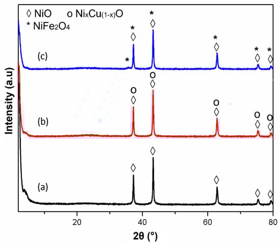
Figure 1.
XRD pattern of the fresh catalysts: (a) 50% Ni/MSN, (b) 50% Ni–5% Cu/MSN and (c) 50% Ni–5% Fe/MSN catalysts.
Similar results were observed in the Ni–Fe/MSN catalyst. No peaks associated with the Fe2O3 phase were detected in the XRD patterns. The existence of Fe in the catalyst was expected to be in the form of spinel nickel ferrites [38], as both samples exhibited similar diffraction peaks [40], as shown in Figure 1. The crystallite size of the metallic oxides (NiO) in all of the catalysts was calculated using the integral breadth over the high peak intensity diffraction peak at the (200) plane. The crystallite size was calculated to be 25.1 nm, 25.6 nm and 26.5 nm for the 50% Ni/MSN, 50% Ni– 5%Cu/MSN and 50% Ni–5% Fe/MSN catalysts, respectively. The crystallite size of NiO was not altered after the incorporation of metal promoters into the catalysts, which is clear from the intensity of the diffraction peaks.
The surface functional groups present in the catalysts were studied by FTIR spectroscopy. The results presented in Figure 2 show three distinct transmission bands at 457 cm−1, 806 cm−1 and 1079 cm−1, which were related to the formation of MSNs [37,43]. These bands can be assigned to the asymmetric and symmetric stretching vibration of the Si–O bonds and the asymmetric stretching vibration of the Si–O–Si bridges, respectively [44]. Another weak band observed at 970 cm−1 could be attributed to the stretching vibration of the Si–OH of the silanol groups [10]. All the transmission bands associated with MSNs were maintained in the catalysts after the addition of Ni and promoters. The weak band observed at 566 cm−1 was related to the bending vibration of the metal–oxygen bond present in the sample [30]. The presence of a broad transmission band at 3431 cm−1 was attributed to the stretching and bending mode vibrations of the hydroxyl group, which were induced by the presence of adsorbed water molecules.
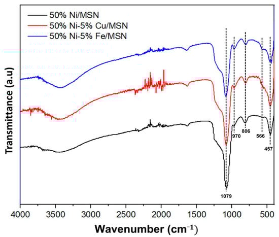
Figure 2.
FTIR spectra of 50% Ni/MSN, 50% Ni–5% Cu/MSN and 50% Ni–5% Fe/MSN catalysts.
The morphology of the prepared catalysts was studied using FESEM analysis, and the results are shown in Figure 3. The catalysts had an irregular morphology with polygonal-shaped and non-uniform irregular particles, which were distributed on the MSN support. The 50% Ni/MSN catalyst displayed nanoparticles with sizes ranging from 50 nm to 200 nm. Meanwhile, the Cu- and Fe-promoted Ni/MSN catalysts exhibited the presence of more nano-sized particles ranging from 30 nm to 60 nm and well-developed tetragonal structures with a size ranging from 100 nm to 200 nm. As shown in the figure, more nanoparticles were accumulated in the promoted catalysts, which decreases the surface area of the Ni/MSN catalyst [29]. This could be due to the additional surface coverage of the MSNs after the addition of metal promoters.
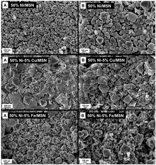
Figure 3.
FESEM images of the prepared catalysts at two different magnifications (A and B).
Figure 4 displays the EDX and elemental mapping analyses of the copper and iron-promoted catalysts. The results confirmed the presence of Cu and Fe as promoter metals in the catalyst where the metallic species were dispersed on the surface of the MSN support.
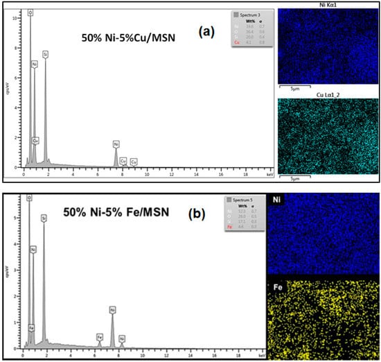
Figure 4.
FESEM–EDX spectra and elemental mapping images of the (a) Cu and (b) Fe-promoted Ni/MSN catalysts.
BET/BJH measurements were performed to study the textural properties of the catalysts. As shown in Table 1, the MSNs possessed a very high surface area of 1095 m2/g and a cumulative pore volume of 1.645 cm3/g, whereas the pore size was found to be 2.9 nm. The surface area and pore volume were drastically decreased upon the loading of metals on the MSN support. This can be associated with the agglomeration of particles on the surface of the MSNs and the blocking of the MSN pores with metal particles, as confirmed by morphological analysis [10,45].

Table 1.
BET/BJH results of the prepared samples.
Figure 5 shows the N2 adsorption/desorption isotherm of the catalysts. The isotherms were type IV isotherms with an H1 hysteresis loop for all of the prepared catalysts, indicating that the particles were uniformly arranged with a cylindrical pore geometry, suggesting uniformity in the pore size distribution of the catalysts. Meanwhile, the 50% Ni/MSN catalyst exhibited type IV isotherms with an H4 hysteresis loop, indicating narrow slit-like pores and hollow spheres with walls composed of ordered mesoporous silica [37]. The inset pore size distribution curves of the catalysts displayed a monomodal pore structure, and the pore size distribution was in the range of 2 to 3.4 nm. This finding was compatible with the mean pore size data provided in Table 1.
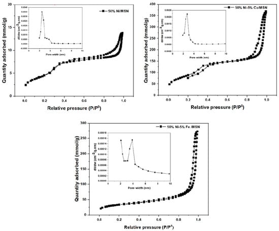
Figure 5.
N2 adsorption–desorption isotherms and pore size distribution curves of 50% Ni/MSN, 50% Ni–5% Cu/MSN and 50% Ni–5% Fe/MSN catalysts.
The reducibility of the unpromoted and Cu and Fe-promoted catalysts was evaluated using TPR analysis. As shown in Figure 6, a clear and well-defined peak centered at 423 °C and one broader reduction hump centered at 577 °C were observed for the 50% Ni/MSN catalyst. The first peak can be associated with the reduction of NiO species with a weak interaction with the MSN support [10]. The latter peak can be ascribed to the reduction of NiO with a strong metal–support interaction [27], as confirmed by Pudukudy et al. [10] who reported that the strong interaction of NiO with the support is developed by the encapsulation of NiO particles inside the SBA-15 mesopore. The 50% Ni–5% Cu/MSN catalyst displayed a small reduction peak at 229 °C, which might be due to the reduction of any copper oxide species in the samples [9,40]. Awad et al. validated the dissociation of H2 molecules into separate atoms with the help of Cu0, which leads to the reduction of NiO by the spillover effect [29]. The reduction peaks of the Ni/MSN shifted toward a lower temperature after the addition of Cu, indicating an improvement in the reducibility of the Ni/MSN catalyst.
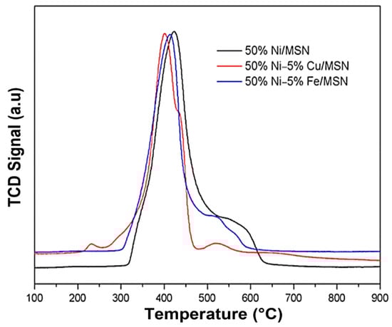
Figure 6.
TPR profile of 50% Ni/MSN, 50% Ni–5% Cu/MSN and 50% Ni–5% Fe/MSN catalysts.
The H2-TPR profile of the 50% Ni–5% Fe/MSN displayed three reduction peaks. The peaks located at 412 °C and 524 °C were attributed to the NiO reduction with weak and strong metal–support interactions, respectively [40]. The last peak centered at 569 °C was related to the reduction of NiFe2O4 species, which agreed with the XRD results [38,42,46]. It is noteworthy that the reducibility of the Ni/MSN catalyst improved upon the addition of Fe, and the reduction temperature moved towards a lower temperature [36], which is in agreement with Park et al. [47], as they reported the effect of the reduction condition on the reaction over the surface of the catalyst as well as the growth mechanism of the carbon nanotubes that are generated after the reaction.
2.2. Catalytic Decomposition of Methane
Methane decomposition is an endothermic process. Thus, the activity would increase as the reaction temperature is increased. Methane decomposition reactions conducted at high temperatures would produce high-quality nanocarbon and enhance the graphitic order of the deposited carbon [48]. The production of multi-walled carbon nanotubes may also increase despite the fact that the aggregation of metal particles may occur at high reaction temperatures [8].
Figure 7 shows the catalytic activity of the prepared catalysts in the methane decomposition. All of the catalysts displayed high initial activity in each of the reaction temperatures. This is attributed to the enhanced textural properties of the MSN support, which provides a high surface area and adequate sites for the active metals initially for the reaction. As can be seen, with an increase in the reaction temperature, the catalytic performance was enhanced for all of the catalysts. However, the Cu and Fe-promoted catalysts exhibited better performance for the reaction compared to the unpromoted catalyst. At 700 °C, the Cu and Fe-promoted Ni/MSN catalysts exhibited higher initial activity compared to the unpromoted catalyst. The highest initial hydrogen yield and final yield measured at 360 min of time on stream were found to be 75% and 73%, 68% and 64% and 64.8% and 61% for the Fe and Cu-promoted and unpromoted catalysts, respectively.
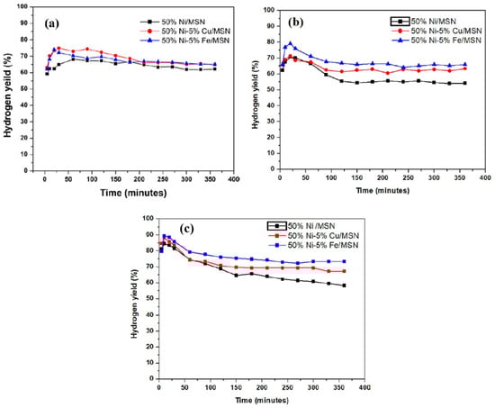
Figure 7.
Catalytic performance of the samples for methane decomposition at various reaction temperatures: (a) 700 °C, (b) 800 °C and (c) 900 °C.
However, all the catalysts exhibited good stability throughout the reaction time, whereas the catalytic activity slightly decreased in all of the catalysts. The high stability could be due to the formation of bimetallic alloys in the catalysts. The decreased activity of the catalysts may be due to the deposition of carbon, which lowers the surface area for the menthane molecules to interact with [48].
As the reaction temperature increased to 800 °C, the unpromoted and promoted catalysts showed the same trend with a high hydrogen yield at the initial stage of the reaction. At this temperature, the 50% Ni–5% Fe/MSN catalyst displayed the highest yield (80%) during the first 20 min, followed by the 50% Ni–5% Cu/MSN and 50%-Ni/MSN catalysts with 71% and 69% of the yield, respectively. After 30 min on stream, the activities of the 50% Ni/MSN, 50% Ni–5% Cu/MSN and 50% Ni–5% Fe/MSN catalysts started to decrease slowly until the end of the reaction, and the yield was measured to be 54%, 63% and 66%, respectively. Furthermore, it is worth mentioning that, as seen in Figure 7b, the stability of the Cu and Fe-promoted catalysts was comparatively higher than that of the unpromoted catalyst, as the hydrogen yield difference during the course of the reaction seemed to be minimum for the promoted catalysts. This could be ascribed to the enhanced role of the bimetallic alloys in the samples [30].
A further increase in the reaction temperature to 900 °C increased the hydrogen yield drastically during the first 10 min of the reaction, with a hydrogen yield of 85%, 88% and 91% for the unpromoted and Cu and Fe-promoted catalysts, respectively. As shown in Figure 7c, the activity of the catalysts started to drop after 20 min on stream. The same kinetic curve trend was observed for all of the catalysts. The hydrogen yield of the 50% Ni–5% Cu/MSN catalyst decreased to 74% and remained more or less the same until 360 min on stream, with a final yield of 67%. The 50% Ni–5% Fe/MSN catalyst displayed better activity and stability at 900 °C, with 74% of the final hydrogen yield. This result may be attributed to the Ni–Fe alloy formation, which decreased the rate of decomposition and then enhanced the carbon diffusion rate on the surface of the metal and, therefore, prevented the catalyst deactivation at high reaction temperatures [32,38]. The introduction of Fe into Ni/MSN helped maintain the stability of the catalyst, even at high temperatures [46]. Catalyst deactivation is reported to occur when the carbon diffusion rate is slower than the carbon formation rate, thus leading to the formation of encapsulating carbon [49]. Carbon encapsulation occurs when carbon starts to build on the surface of the catalyst and then encapsulates the metal particles. The high surface area and porosity of the MSNs helped to prevent the agglomeration of metal particles on the MSN support. As a result, all the catalysts achieved adequate stability throughout 360 min of the reaction conducted at high temperatures up to 900 °C. This catalytic performance indicated that the enhanced properties of the promoted catalyst were achieved at higher reaction temperatures owing to the formation of bimetallic alloys [50]. Additionally, at high reaction temperatures, the Ni–Cu or Ni–Fe alloys generated a quasi-liquid condition, then averted the fragmentation process, which led to the generation of small particles as well as the rearrangement of the structural and electronic properties, which prevented the catalysts from agglomerating and then preserved their catalytic stability [51].
2.3. Characterisation of Spent Catalysts
Carbon yield is defined as the ratio of the amount of carbon deposited over the catalyst to the total amount of metallic species present in the catalyst that has been used initially in the decomposition reaction. The yield of carbon obtained after the decomposition reaction at three different reaction temperatures was further calculated using Equation (2), and the results are shown in Figure 8. As can be seen, with an increase in the reaction temperature, the carbon yield increased significantly. The highest carbon yield was obtained for the methane decomposition reaction at 900 °C. The yield was calculated to be 1254%, 1572% and 1896% for the unpromoted Ni/MSN and Cu and Fe-promoted Ni/MSN catalysts at 900 °C, respectively. The increase in the carbon yield could be attributed to the higher conversion of methane at high temperatures over the present catalysts. As expected, the Fe-promoted catalyst exhibited the highest carbon yield as the highest yield of hydrogen was also obtained for the same catalyst. Thus, consistency in the product yield was observed in the methane decomposition reaction.
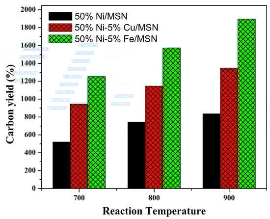
Figure 8.
Carbon yield at various reaction temperatures over 50% Ni/MSN and 5% Cu and 5% Fe–promoted 50% Ni/MSN catalysts.
The morphology and the graphitization degree of the carbon produced by the spent catalysts were further evaluated using XRD, FESEM, Raman and TEM analyses.
Figure 9 displays the XRD patterns of the 50% Ni/MSN, 50% Ni–5% Cu/MSN and 50% Ni–5% Fe/MSN catalysts after the methane decomposition reaction at 900 °C. The well-defined peak centered at 26.3° in all the catalysts was assigned to the presence of graphitic carbon in the spent catalysts. The most intense carbon peak with the highest intensity was achieved by the 50% Ni–5% Fe/MSN catalyst (Figure 8c), which demonstrated that the high crystallinity of nanocarbon was produced with the introduction of Fe at high reaction temperatures. This result agrees with the findings of Torres et al. [48]. Additionally, the d-spacing values of the 26.3° diffraction peaks of the 50% Ni/MSN, 50% Ni–5% Cu/MSN and 50% Ni–5% Fe/MSN spent catalysts were calculated to be 0.3357 nm, 0.3356 nm and 0.3355 nm, respectively. These values were close to the ideal value for a graphite-like structure, which is 0.34 nm, representing a higher quality of carbon produced in this study on the structure and oxidation activity of the solid carbon produced from the catalytic decomposition of methane [52].
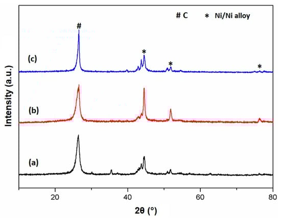
Figure 9.
XRD pattern of the spent catalysts: (a) 50% Ni/MSN, (b) 50% Ni–5% Cu/MSN and (c) 50% Ni–5% Fe/MSN at reaction temperature of 900 °C.
The other small peak located at 43.7° also belonged to the graphitic carbon. Furthermore, the diffraction peaks at 44.5° and 51.9° were associated with the presence of metallic Ni and Cu and Fe-based bimetallic nickel alloy species in the catalysts. This result indicates that NiO or metallic oxide species were completely reduced to metallic Ni or bimetallic alloys during the pre-treatment steps of the reaction. The higher intensity of these Ni0 peaks in the 50% Ni–5% Cu/MSN catalyst (Figure 8b) demonstrated the higher crystallinity of the Ni–Cu alloy particles by the reduction treatment [53]. The other peaks were related to the formation of metallic carbides formed by the reaction of the metals present in the catalyst with the formed carbon at high reaction temperatures, as reported by Pudukudy et al. [54]. The formation of these bimetallic alloys, especially the Ni–Fe alloy, enhanced the hydrogen yield and stability of the Ni catalyst at high temperatures.
Raman spectroscopy was employed to study the crystallinity and graphitization degree of the carbon deposited over the catalysts, and the results are shown in Figure 10. Each catalyst displays two well-defined peaks related to the D-band and G-band. The D-band centered at 1340 cm−1 is assigned to the presence of disordered carbon in the graphitic carbon, whereas the G-band centered at 1570 cm−1 is attributed to the stretching vibration of in-plane carbon-carbon bonds [53]. The ID/IG ratios were found to be 0.82, 0.79 and 0.54 for the 50% Ni/MSN, 50% Ni–5% Cu/MSN and 50% Ni–5% Fe/MSN spent catalysts, respectively. The decreases in the ID/IG ratio indicated the improved crystallinity and graphitization degree of the carbon produced at high reaction temperatures.

Figure 10.
Raman spectra of the spent catalysts: (a) 50% Ni/MSN, (b) 50% Ni–5% Cu/MSN and (c) 50% Ni–5% Fe/MSN at a reaction temperature of 900 °C.
The morphological features of the spent catalysts were investigated by FESEM analysis. As the highest carbon yield was obtained for the Fe-promoted Ni/MSN catalyst, it was further selected for the morphological studies and FESEM micrographs at two different magnifications, as shown in Figure 11. As can be seen, the surfaces of the catalysts were found to be accumulated with the bulk amount of carbon nanotubes (CNTs). The detailed examination of the deposited carbon nanotubes validates the existence of open tips in the CNTs. The lengths of the deposited CNTs were found to vary greatly, whereas the widths were observed to be in the range of 40 nm to 80 nm. The development of the open tips can be attributed to the presence of a strong metal–support interaction in the catalyst. The strong metal–support interaction could be attributed to the encapsulation of metallic nanoparticles on the mesopores of the MSN support. As a result of this, the carbon crystal tends to grow by a base growth mechanism followed by an open tip, while the metal tends to be at the bottom portion of the carbon nanotube [10].
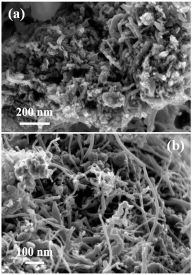
Figure 11.
FESEM images of the spent 5%Fe–50%Ni/MSN catalyst obtained after methane decomposition at 900 °C at two different scale bars (a) 200 nm and (b) 100 nm.
Figure 12 shows the internal morphology of the deposited nanocarbon obtained at 900 °C. The carbon was deposited in the form of a filamentous structure in all of the catalysts. The TEM images showed that the produced filamentous carbon was in the form of multi-walled carbon nanotubes with open tips and diameters ranging from 45 nm to 70 nm. An internal hollow channel diameter of 10 nm to 35 nm was observed for the CNTs, regardless of the role of the promoters in the catalysts. In addition, a bamboo-like internal tube structure was observed for the nanotubes, and some of the metal/alloy nanoparticles were found to be encapsulated inside the carbon nanotubes, which is clearly evident in the TEM images of the Cu-promoted spent catalysts. The metal nanoparticles with a weak metal–support interaction could suffer the encapsulation process.
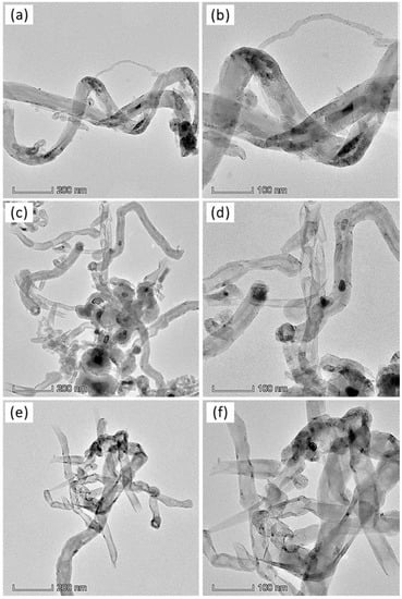
Figure 12.
TEM images of nanocarbon obtained over (a,b) 50% Ni /MSN, (c,d) 50% Ni–5% Cu/MSN and (e,f) 50% Ni–5% Fe/MSN at a reaction temperature of 900 °C.
3. Materials and Methods
3.1. Preparation of the Catalysts
The catalyst support, Mesostructured Silica Nanoparticles (MSNs), was synthesized according to our previous work [38]. Firstly, 9.68 g cetyltrimethylammonium bromide (Merck, New York, NY, USA), 58 mL of ammonia solution and 240 mL of ethylene glycol (Merck) were dissolved in 1440 mL of deionized water and then stirred at 50 °C for 30 min. Then, 11.4 mL of tetraethyl orthosilicate (Merck) and 2.1 mL of 3-(triethoxysilyl)-propylamine (Merck), which act as silica precursors, were added slowly to the mixture, thereby turning the clear mixture into a white suspension. Then, the solution was further stirred at 80 °C for 2 h. Afterwards, the white solution was kept in a refrigerator for separation into two layers. After several days, the white precipitate separated in the solution was collected and washed several times with a distilled water and ethanol mixture at a ratio of 1:1. The obtained as-synthesized MSNs were dried in the oven overnight at 110 °C and then calcined for 3 h at 550 °C.
A co-impregnation method was employed in the synthesis of the metal-loaded MSN catalysts. The desired amount of Ni salt, such as Ni(NO3)2·6H2O with 50 wt.% of metallic nickel, in the final sample was weighed and then dissolved in 500 mL of deionized water. The nitrate salts of the co-metal promoters, such as hydrated nitrated salts of Cu and Fe, having 5 wt.% of each metal promoter, were also added. Then, the prepared MSN powder was added slowly to the mixed-metal salt aqueous solution and heated at 90 °C and mixed well with a magnetic stirrer until it became a homogenous paste. After that, the paste was dried at 110 °C overnight and finally calcined at 550 °C for 3 h. The resulting catalysts were in the form of a colored powder and were named 50% Ni/MSN, 50% Ni–5% Cu/MSN and 50% Ni–5% Fe/MSN.
3.2. Characterization of the Catalysts
The physical and chemical properties of the fresh catalyst samples were studied by various methods. X-ray diffraction analysis was used to determine the crystalline structure of the catalysts using a D8 Focus Advance powder diffractometer (Bruker, Billerica, MA, USA) with Cu Kα monochromatic radiation with a wavelength, λ, of 1.5406 Å. The diffraction angle was set from 0 to 80°, and the crystallite sizes were calculated using the Scherrer equation. The functional groups present in the catalysts were determined using Fourier Transform Infrared spectroscopy (FTIR, Thermo Scientific NICOLET 6700 apparatus, Waltham, MA, USA) performed in the range of 400 to 4000 cm−1 at room temperature. The nitrogen adsorption–desorption isotherms, together with the surface area, pore size distribution and pore volume, were measured using the BET/BJH method in a Micromeritics ASAP 2020 chemisorption analyzer (Norcross, GA, USA) at −196 °C. The treatment began as the samples were degassed at 300 °C for 3 h before the analysis was carried out. Temperature-programmed reduction (TPR) analysis was carried out to study the reducibility of the catalyst using a Thermo Finnigan TPDRO 1100 model (San Jose, CA, USA). The surface morphology of the catalysts and the spent catalysts was studied using a field emission scanning electron microscope (FESEM) conducted in a Zeiss MERLIN COMPACT machine (Carl Zeiss, Jena, Germany) with an accelerating voltage of 3 kV. The deposited carbon was analyzed by Raman spectroscopy (Thermo Scientific, DXR2xi) and a transmission electron microscope (TEM) (Thermo Fisher Talos 120C model, Waltham, MA, USA).
3.3. Investigation of the Catalytic Performance for Methane Decomposition
The activity of the catalyst was studied for the decomposition of undiluted methane at various reaction temperatures (700–900 °C). The reactions were conducted in a tubular fixed-bed reactor made of stainless steel (height of 60 cm; outer diameter of 3.1 cm; inner diameter of 2.5 cm), which was heated by an electric muffle under atmospheric pressure. The desired weight of the catalyst (1.0 g) was packed in the middle of the reactor. The catalyst was reduced in-situ with hydrogen (150 mL/min) at 600 °C for 90 min. After that, nitrogen gas (150 mL/min) was introduced into the reactor to increase the temperature of the reactor to the desired temperature. The catalytic testing was carried out at atmospheric pressure (0.1 MPa) with a flow of undiluted methane (100 mL/min) for 360 min on stream. The products of the outlet gases were collected in gas bags and were analyzed by a gas chromatograph, GC 2014C (Shimadzu, Osaka, Japan), equipped with a TDX-01 column connected to a thermal conductivity detector (TCD), using helium as the carrier gas. At the end of the experiments, the reactor was flushed with nitrogen (50 mL/min) to cool down the reactor and, thus, the spent catalyst in the form of carbon was taken for further analysis. The hydrogen yield and carbon yield were calculated according to the following Equations (1) and (2)
4. Conclusions
Ni/MSN catalysts with Cu and Fe-promoters were synthesized by using an impregnation method, and their performance in methane decomposition was investigated at 700 °C, 800 °C and 900 °C. Fine dispersion of the active phase NiO and Cu and Fe-incorporated NiO on the MSN surface with proper metal–support interaction was achieved. Catalytic activity tests revealed that both the hydrogen yield and stability of the Ni/MSN catalyst increased upon the incorporation of Cu and Fe at all of the reaction temperatures. The pronounced performance of the catalyst at high temperatures could be attributed to the enhanced synergistic effects between the metallic nickel species and the MSN support, together with the formation of a bimetallic alloy, which enhanced the stability of the Ni/MSN catalyst, even at high temperatures. The improved performance of the Ni/MSN catalysts in methane decomposition can be ascribed to the high surface area, fine dispersion of the metal species on the surface of the support, an appropriate metal–support interaction and the presence of bimetallic alloy nanoparticles. The characterization studies of the deposited carbon showed that MWCNTs with a high crystallinity and graphitization degree formed over the catalysts after the methane decomposition reaction.
Author Contributions
Conceptualization, N.S.N.H. and M.P.; methodology, N.S.N.H., M.P. and S.N.T.; Validation, N.S.N.H. and M.P.; Formal analysis, N.S.N.H., M.P. and S.N.T.; Investigation, N.S.N.H. and Z.Y.; Data curation, N.S.N.H., M.P., N.H.N.K., K.L.L. and S.N.T.; Writing—original draft preparation, N.S.N.H. and M.P.; Writing—review and editing, N.S.N.H., M.P., S.N.T., Z.Y., N.H.N.K. and K.L.L.; Supervision, M.P. and S.N.T.; Project administration, S.N.T.; Funding acquisition, S.N.T. All authors have read and agreed to the published version of the manuscript.
Funding
The authors gratefully acknowledge the financial supports from University Research Grants [GUP-2022-079] and [PP-SELFUEL-2023].
Data Availability Statement
Data are available upon request.
Acknowledgments
The authors acknowledge the Centre of Research and Instrumentation Management (CRIM) and the Faculty of Science and Technology (FST), Universiti Kebangsaan Malaysia (UKM) for the characterization of materials.
Conflicts of Interest
The authors declare no conflict of interest.
References
- Elavarasan, R.M. The Motivation for Renewable Energy and its Comparison with Other Energy Sources: A Review. Eur. J. Sustain. Dev. Res. 2019, 3, em0076. [Google Scholar] [CrossRef] [PubMed]
- Liu, H.; Xu, L.; Han, Y.; Chen, X.; Sheng, P.; Wang, S.; Huang, X.; Wang, X.; Lu, C.; Luo, H.; et al. Development of a gaseous and solid-state hybrid system for stationary hydrogen energy storage. Green Energy Environ. 2021, 6, 528–537. [Google Scholar] [CrossRef]
- Yang, H.; Han, Y.J.; Yu, J.; Kim, S.; Lee, S.; Kim, G.; Lee, C. Exploring Future Promising Technologies in Hydrogen Fuel Cell Transportation. Sustainability 2022, 14, 917. [Google Scholar] [CrossRef]
- Singla, M.K.; Nijhawan, P.; Oberoi, A.S. Hydrogen fuel and fuel cell technology for cleaner future: A review. Environ. Sci. Pollut. Res. 2021, 28, 15607–15626. [Google Scholar] [CrossRef]
- Balat, H.; Kırtay, E. Hydrogen from biomass—Present scenario and future prospects. Int. J. Hydrogen Energy 2010, 35, 7416–7426. [Google Scholar] [CrossRef]
- Abánades, A.; Rubbia, C.; Salmieri, D. Thermal cracking of methane into Hydrogen for a CO2-free utilization of natural gas. Int. J. Hydrogen Energy 2013, 38, 8491–8496. [Google Scholar] [CrossRef]
- Fan, Z.; Weng, W.; Zhou, J.; Gu, D.; Xiao, W. Catalytic decomposition of methane to produce hydrogen: A review. J. Energy Chem. 2021, 58, 415–430. [Google Scholar] [CrossRef]
- Pudukudy, M.; Yaakob, Z.; Mazuki, M.Z.; Takriff, M.S.; Jahaya, S.S. One-pot sol-gel synthesis of MgO nanoparticles supported nickel and iron catalysts for undiluted methane decomposition into COx free hydrogen and nanocarbon. Appl. Catal. B Environ. 2017, 218, 298–316. [Google Scholar] [CrossRef]
- Naresh, G.; Vijay Kumar, V.; Anjaneyulu, C.; Tardio, J.; Bhargava, S.K.; Patel, J.; Venugopal, A. Nano size Hβ zeolite as an effective support for Ni and NiCu for COx free hydrogen production by catalytic decomposition of methane. Int. J. Hydrogen Energy 2016, 41, 19855–19862. [Google Scholar] [CrossRef]
- Pudukudy, M.; Yaakob, Z.; Akmal, Z.S. Direct decomposition of methane over Pd promoted Ni/SBA-15 catalysts. Appl. Surf. Sci. 2015, 353, 127–136. [Google Scholar] [CrossRef]
- Kuvshinov, D.G.; Kurmashov, P.B.; Bannov, A.G.; Popov, M.V.; Kuvshinov, G.G. Synthesis of Ni-based catalysts by hexamethylenetetramine-nitrates solution combustion method for co-production of hydrogen and nanofibrous carbon from methane. Int. J. Hydrogen Energy 2019, 44, 16271–16286. [Google Scholar] [CrossRef]
- Al-Fatesh, A.S.; Kasim, S.O.; Ibrahim, A.A.; Al-Awadi, A.S.; Abasaeed, A.E.; Fakeeha, A.H.; Awadallah, A.E. Catalytic methane decomposition over ZrO2 supported iron catalysts: Effect of WO3 and La2O3 addition on catalytic activity and stability. Renew. Energy 2020, 155, 969–978. [Google Scholar] [CrossRef]
- Somekawa, S.; Yanagi, S.; Yamanaka, T.; Hayashi, H. Preparation of Ni/12CaO⋅7Al2O3 honeycomb-type catalyst for continuous production of hydrogen by methane decomposition. Inorg. Chem. Commun. 2022, 140, 109401. [Google Scholar] [CrossRef]
- Zhang, X.; Zhang, M.; Zhang, J.; Zhang, Q.; Tsubaki, N.; Tan, Y.; Han, Y. Methane decomposition and carbon deposition over Ni/ZrO2 catalysts: Comparison of amorphous, tetragonal, and monoclinic zirconia phase. Int. J. Hydrogen Energy 2019, 44, 17887–17899. [Google Scholar] [CrossRef]
- Hanifa, N.H.E.; Ismail, M.; Ideris, A. Methane decomposition over Ni supported on palm oil fuel ash (Ni-POFA) catalyst. Chem. Eng. Res. Des. 2022, 178, 224–231. [Google Scholar] [CrossRef]
- Muhammad, A.F.A.S.; Awad, A.; Saidur, R.; Masiran, N.; Salam, A.; Abdullah, B. Recent advances in cleaner hydrogen productions via thermo-catalytic decomposition of methane: Admixture with hydrocarbon. Int. J. Hydrogen Energy 2018, 43, 18713–18734. [Google Scholar] [CrossRef]
- Urdiana, G.; Valdez, R.; Lastra, G.; Valenzuela, M.Á.; Olivas, A. Production of hydrogen and carbon nanomaterials using transition metal catalysts through methane decomposition. Mater. Lett. 2018, 217, 9–12. [Google Scholar] [CrossRef]
- Awadallah, A.; Ahmed, W.; El-Din, M.N.; Aboul-Enein, A. Novel aluminosilicate hollow sphere as a catalyst support for methane decomposition to COx-free hydrogen production. Appl. Surf. Sci. 2013, 287, 415–422. [Google Scholar] [CrossRef]
- Tapia-Parada, K.; Valverde-Aguilar, G.; Mantilla, A.; Valenzuela, M.A.; Hernández, E. Synthesis and characterization of Ni/Ce–SiO2 and Co/Ce–TiO2 catalysts for methane decomposition. Fuel 2013, 110, 70–75. [Google Scholar] [CrossRef]
- Hasnan, N.S.N.; Timmiati, S.N.; Lim, K.L.; Yaakob, Z.; Kamaruddin, N.H.N.; Teh, L.P. Recent developments in methane decomposition over heterogeneous catalysts: An overview. Mater. Renew. Sustain. Energy 2020, 9, 8. [Google Scholar] [CrossRef]
- Pizzolitto, C.; Pupulin, E.; Menegazzo, F.; Ghedini, E.; Di Michele, A.; Mattarelli, M.; Cruciani, G.; Signoretto, M. Nickel based catalysts for methane dry reforming: Effect of supports on catalytic activity and stability. Int. J. Hydrogen Energy 2019, 44, 28065–28076. [Google Scholar] [CrossRef]
- Chen, Y.; Qiu, B.; Liu, Y.; Zhang, Y. An active and stable nickel-based catalyst with embedment structure for CO2 methanation. Appl. Catal. B Environ. 2020, 269, 118801. [Google Scholar] [CrossRef]
- Azali, N.S.; Kamarudin, N.H.N.; Jaafar, J.A.; Timmiati, S.N.; Sajab, M.S. Modification of mesoporous silica nanoparticles with pH responsive polymer poly (2-vinylpyrrolidone) for the release of 5-Florouracil. Mater. Today Proc. 2020, 31, A12–A17. [Google Scholar] [CrossRef]
- Roblero, J.; Pola-Albores, F.; Valenzuela, M.; Rojas-García, E.; Ríos-Valdovinos, E.; Valverde-Aguilar, G. Ni and Ni3C catalysts supported on mesoporous silica for dry reforming of methane. Int. J. Hydrogen Energy 2019, 44, 10473–10483. [Google Scholar] [CrossRef]
- Wei, Y.; Yang, W.; Yang, Z. An excellent universal catalyst support-mesoporous silica: Preparation, modification and applications in energy-related reactions. Int. J. Hydrogen Energy 2022, 47, 9537–9565. [Google Scholar] [CrossRef]
- Al Mesfer, M.K.; Danish, M.; Shah, M. Synthesis and optimization of hydrotalcite derived Ni-Fe-Cu based catalysts for catalytic methane decomposition process using the design of experiment approach. J. Taiwan Inst. Chem. Eng. 2021, 128, 370–379. [Google Scholar] [CrossRef]
- Pudukudy, M.; Yaakob, Z. Methane decomposition over Ni, Co and Fe based monometallic catalysts supported on sol gel derived SiO2 microflakes. Chem. Eng. J. 2015, 262, 1009–1021. [Google Scholar] [CrossRef]
- Saraswat, S.K.; Pant, K. Synthesis of carbon nanotubes by thermo catalytic decomposition of methane over Cu and Zn promoted Ni/MCM-22 catalyst. J. Environ. Chem. Eng. 2013, 1, 746–754. [Google Scholar] [CrossRef]
- Awad, A.; Masiran, N.; Salam, M.A.; Vo, D.-V.N.; Abdullah, B. Non-oxidative decomposition of methane/methanol mixture over mesoporous Ni-Cu/Al2O3 Co-doped catalysts. Int. J. Hydrogen Energy 2019, 44, 20889–20899. [Google Scholar] [CrossRef]
- Pudukudy, M.; Yaakob, Z.; Akmal, Z.S. Direct decomposition of methane over SBA-15 supported Ni, Co and Fe based bimetallic catalysts. Appl. Surf. Sci. 2015, 330, 418–430. [Google Scholar] [CrossRef]
- Lua, A.C.; Wang, H.Y. Hydrogen production by catalytic decomposition of methane over Ni-Cu-Co alloy particles. Appl. Catal. B Environ. 2014, 156, 84–93. [Google Scholar] [CrossRef]
- Bayat, N.; Rezaei, M.; Meshkani, F. Hydrogen and carbon nanofibers synthesis by methane decomposition over Ni–Pd/Al2O3 catalyst. Int. J. Hydrogen Energy 2016, 41, 5494–5503. [Google Scholar] [CrossRef]
- Rategarpanah, A.; Meshkani, F.; Wang, Y.; Arandiyan, H.; Rezaei, M. Thermocatalytic conversion of methane to highly pure hydrogen over Ni–Cu/MgO·Al2O3 catalysts: Influence of noble metals (Pt and Pd) on the catalytic activity and stability. Energy Convers. Manag. 2018, 166, 268–280. [Google Scholar] [CrossRef]
- Cunha, A.; Órfão, J.; Figueiredo, J. Methane decomposition on Ni–Cu alloyed Raney-type catalysts. Int. J. Hydrogen Energy 2009, 34, 4763–4772. [Google Scholar] [CrossRef]
- Tezel, E.; Figen, H.E.; Baykara, S.Z. Hydrogen production by methane decomposition using bimetallic Ni–Fe catalysts. Int. J. Hydrogen Energy 2019, 44, 9930–9940. [Google Scholar] [CrossRef]
- Silva, J.A.; Santos, J.B.O.; Torres, D.; Pinilla, J.L.; Suelves, I. Natural Fe-based catalysts for the production of hydrogen and carbon nanomaterials via methane decomposition. Int. J. Hydrogen Energy 2021, 46, 35137–35148. [Google Scholar] [CrossRef]
- Hasnan, N.S.N.; Timmiati, S.N.; Pudukudy, M.; Yaakob, Z.; Lim, K.L.; Taufiq-Yap, Y.H. Catalytic decomposition of methane into hydrogen and carbon nanotubes over mesostructured silica nanoparticle-supported nickel catalysts. J. Porous Mater. 2020, 27, 369–382. [Google Scholar] [CrossRef]
- Bayat, N.; Rezaei, M.; Meshkani, F. Methane decomposition over Ni–Fe/Al2O3 catalysts for production of COx-free hydrogen and carbon nanofiber. Int. J. Hydrogen Energy 2016, 41, 1574–1584. [Google Scholar] [CrossRef]
- Pudukudy, M.; Kadier, A.; Yaakob, Z.; Takriff, M.S. Non-oxidative thermocatalytic decomposition of methane into COx free hydrogen and nanocarbon over unsupported porous NiO and Fe2O3 catalysts. Int. J. Hydrogen Energy 2016, 41, 18509–18521. [Google Scholar] [CrossRef]
- Li, Y.; Zhang, B.; Xie, X.; Liu, J.; Xu, Y.; Shen, W. Novel Ni catalysts for methane decomposition to hydrogen and carbon nanofibers. J. Catal. 2006, 238, 412–424. [Google Scholar] [CrossRef]
- Lazaro, M.; Echegoyen, Y.; Alegre, C.; Suelves, I.; Moliner, R.; Palacios, J. TiO2 as textural promoter on high loaded Ni catalysts for methane decomposition. Int. J. Hydrogen Energy 2008, 33, 3320–3329. [Google Scholar] [CrossRef]
- Wang, D.; Zhang, J.; Sun, J.; Gao, W.; Cui, Y. Effect of metal additives on the catalytic performance of Ni/Al2O3 catalyst in thermocatalytic decomposition of methane. Int. J. Hydrogen Energy 2019, 44, 7205–7215. [Google Scholar] [CrossRef]
- Sidik, S.; Triwahyono, S.; Jalil, A.; Majid, Z.; Salamun, N.; Talib, N.; Abdullah, T. CO2 reforming of CH4 over Ni–Co/MSN for syngas production: Role of Co as a binder and optimization using RSM. Chem. Eng. J. 2016, 295, 1–10. [Google Scholar] [CrossRef]
- Sidik, S.M.; Jalil, A.A.; Triwahyono, S.; Asli, U.A. CO2 Reforming of Methane Over Ni Supported on Mesostructured Silica Nanoparticles (Ni/Msn): Effect of Ni Loading. J. Teknol. 2016, 78, 13–18. [Google Scholar] [CrossRef]
- Saraswat, S.K.; Pant, K. Synthesis of hydrogen and carbon nanotubes over copper promoted Ni/SiO2 catalyst by thermocatalytic decomposition of methane. J. Nat. Gas Sci. Eng. 2013, 13, 52–59. [Google Scholar] [CrossRef]
- Wang, W.; Wang, H.; Yang, Y.; Jiang, S. Ni–SiO2 and Ni–Fe–SiO2 catalysts for methane decomposition to prepare hydrogen and carbon filaments. Int. J. Hydrogen Energy 2012, 37, 9058–9066. [Google Scholar] [CrossRef]
- Park, S.J.; Kim, K.-D.; Park, Y.S.; Go, K.S.; Kim, W.; Kim, M.; Nho, N.S.; Lee, D.H. Effect of reduction conditions of Mo-Fe/MgO on the formation of carbon nanotube in catalytic methane decomposition. J. Ind. Eng. Chem. 2022, 109, 384–396. [Google Scholar] [CrossRef]
- Torres, D.; Pinilla, J.L.; Suelves, I. Screening of Ni-Cu bimetallic catalysts for hydrogen and carbon nanofilaments production via catalytic decomposition of methane. Appl. Catal. A Gen. 2018, 559, 10–19. [Google Scholar] [CrossRef]
- Nuernberg, G.D.B.; Foletto, E.L.; Campos, C.E.M.; Fajardo, H.V.; Carreño, N.L.V.; Probst, L.F.D. Direct decomposition of methane over Ni catalyst supported in magnesium aluminate. J. Power Sources 2012, 208, 409–414. [Google Scholar] [CrossRef]
- Chai, S.-P.; Zein, S.H.S.; Mohamed, A.R. COx-Free Hydrogen and Carbon Nanofibers Produced from Direct Decomposition of Methane on Nickel-Based Catalysts. J. Nat. Gas Chem. 2006, 15, 253–258. [Google Scholar] [CrossRef]
- Karimi, S.; Bibak, F.; Meshkani, F.; Rastegarpanah, A.; Deng, J.; Liu, Y.; Dai, H. Promotional roles of second metals in catalyzing methane decomposition over the Ni-based catalysts for hydrogen production: A critical review. Int. J. Hydrogen Energy 2021, 46, 20435–20480. [Google Scholar] [CrossRef]
- Chen, J.; Yang, X.; Li, Y. Investigation on the structure and the oxidation activity of the solid carbon produced from catalytic decomposition of methane. Fuel 2010, 89, 943–948. [Google Scholar] [CrossRef]
- Awadallah, A.E.; El-Desouki, D.S.; Aboul-Gheit, N.A.K.; Ibrahim, A.H.; Aboul-Gheit, A.K. Effect of crystalline structure and pore geometry of silica based supported materials on the catalytic behavior of metallic nickel particles during methane decomposition to COx-free hydrogen and carbon nanomaterials. Int. J. Hydrogen Energy 2016, 41, 16890–16902. [Google Scholar] [CrossRef]
- Pudukudy, M.; Yaakob, Z.; Dahani, N.; Takriff, M.S.; Hassan, N.S.M. Production of COx free hydrogen and nanocarbon via methane decomposition over unsupported porous nickel and iron catalysts. J. Clust. Sci. 2017, 28, 1579–1594. [Google Scholar] [CrossRef]
Disclaimer/Publisher’s Note: The statements, opinions and data contained in all publications are solely those of the individual author(s) and contributor(s) and not of MDPI and/or the editor(s). MDPI and/or the editor(s) disclaim responsibility for any injury to people or property resulting from any ideas, methods, instructions or products referred to in the content. |
© 2023 by the authors. Licensee MDPI, Basel, Switzerland. This article is an open access article distributed under the terms and conditions of the Creative Commons Attribution (CC BY) license (https://creativecommons.org/licenses/by/4.0/).