Article

Pt1−xNix Alloy Nanoparticles Embedded in Self-Grown Carbon Nanofibers: Synthesis, Properties and Catalytic Activity in HER

1
Nikolaev Institute of Inorganic Chemistry SB RAS, 3 Lavrentyev Ave., 630090 Novosibirsk, Russia
2
Boreskov Institute of Catalysis SB RAS, 5 Lavrentyev Ave., 630090 Novosibirsk, Russia
3
Department of Natural Science, Novosibirsk State University, 1 Pirogova Str., 630090 Novosibirsk, Russia
4
Department of Chemistry and Chemical Technology, Omsk State Technical University, 11 Mira Ave., 644050 Omsk, Russia
*
Author to whom correspondence should be addressed.
Catalysts 2023, 13(3), 599; https://doi.org/10.3390/catal13030599
Submission received: 9 February 2023 / Revised: 12 March 2023 / Accepted: 14 March 2023 / Published: 16 March 2023
(This article belongs to the Special Issue Ni-Based Catalysts: Synthesis and Applications)

Abstract

:
The development of new heterogeneous Pt-containing catalysts has retained its relevance over the past decades. The present paper describes the method to produce metal–carbon composites, Pt1−xNix/CNF, with an adjustable Pt/Ni ratio. The composites represent Pt1−xNix (x = 0.0–1.0) nanoparticles embedded within a structure of carbon nanofibers (CNF). The synthesis of the composites is based on a spontaneous disintegration of Pt1−xNix alloys in an ethylene-containing atmosphere with the formation of CNF. The initial Pt1−xNix alloys were prepared by thermolysis of multicomponent precursors. They possess a porous structure formed by fragments of 100–200 nm. As was shown by X-ray diffraction analysis, the crystal structure of the alloys containing 0–30 and 60–100 at.% Ni corresponds to a fcc lattice based on platinum (Fm-3m), while the Pt0.50Ni0.50 sample is an intermetallic compound with the tetragonal structure (P4/mmm). The impact of the Ni content in the Pt1−xNix samples on their activity in ethylene decomposition was studied as well. As was revealed, the efficiency of Pt1−xNix alloys in this process increases with the rise of Ni concentration. The composite samples were examined in an electrochemical hydrogen evolution reaction. The synthesized Pt1-xNix/CNF composites demonstrated superior activity if compared with the Pt/Vulcan commercial catalyst.

1. Introduction

Nowadays, fuel cells are considered a real alternative to energy sources working on fossil fuels [1,2]. Due to their attractive performance characteristics, such as high efficiency, low emissions, quiet operation, and portability, fuel cells differ from other alternative energy sources, which opens up opportunities for their application in cars and portable electronics. Low-temperature fuel cells based on a proton-exchange membrane fuel cell (PEMFC) are of greatest interest [3,4]. The key component of such fuel cells is a membrane-electrode block, on the anode and cathode of which the catalytic reactions of fuel oxidation (hydrogen, methanol, or formic acid) [5,6,7,8] and oxidant reduction (air oxygen) [9] proceed, respectively. The most widely used catalyst in fuel cells is platinum, the use of which is disadvantaged by its high cost [10,11,12]. The use of bimetallic (alloy) catalytic systems based on platinum with the inclusion of other cheaper metals, which give the catalysts the desired properties, can solve these problems. The introduction of the second metal can result in a certain improvement in the stability of the catalyst and an increase in the duration of its operation. For example, bimetallic Pt-M catalysts possess a significantly higher tolerance towards CO impurities contained in the fuel if compared to pure platinum [13]. As second metals, Co, Ni, Fe, Ru, and Cr are widely studied [14,15,16]. Unlike clusters of pure Pt, particles of Pt-M alloys have a lower tendency to agglomerate. The presence of an alloying component decreases the mobility of Pt on the support [17,18]. In addition, the use of alloys has a positive effect on the resistance of platinum catalysts to corrosion in acidic and alkaline media [19]. The alloys are more tolerant to methanol as well since alloying metals suppress Pt dissolution and prevent methanol adsorption on the catalyst’s surface [20,21]. Thus, an important scientific problem is the creation of catalytic systems characterized by high stability under the conditions of the long-term operation of fuel cells. The use of alloy particles is one of the approaches allowing for improvement of the stability of the catalysts used in the fuel cells. In the future, such materials may replace the currently used monometallic platinum catalysts.
Most commonly, electrochemical catalysts containing alloy particles of platinum with other metals are prepared via impregnation of the carbon support with a solution of metal salts, followed by heat treatment or chemical reduction (for example, sodium borohydride) [22,23,24,25,26]. Many catalysts containing bi- or trimetallic nanosized alloy particles distributed over the surface of the carbon support have been thus obtained. Among them, systems such as Pt1−xCox/CVulcan [27], Pt1−xNix/CVulcan [28,29], Pt1−xFex/CVulcan [14,30], Pt1−xFex/N-C [31], Pt1−xCux/C [32,33], PtNi3Cr/C [32], Pt1−xSnx/Cgraphene [34], Pt1−xRux/N-C [35], and Pt1−xPbx/CVulcan [36] should be mentioned. These catalysts exhibit sufficiently high activity in the reactions of oxygen reduction and methanol or hydrogen oxidation. The mentioned approach is relatively easy to use but does not guarantee a narrow particle size distribution. The main disadvantage of the impregnated catalysts is the remaining tendency of deposited alloy particles to deactivate due to their washing out or surface migration and agglomeration.
Another approach, the synthesis of carbon nanofibers (CNF) by catalytic chemical vapor deposition (CCVD) on alloys of a given composition, seems to be more promising for the preparation of electrochemical catalysts [37,38,39,40]. By using this method, it is possible to obtain a composite catalyst, in which the active alloy particles are embedded within the structure of carbon nanofibers. Such composites are expected to be resistant to leaching and agglomeration processes. Note that, in this case, the synthesis of carbon material, which acts as a support of alloy particles, occurs directly during the catalytic decomposition of hydrocarbons over these particles. At the initial stage of this process, carbon erosion (CE) of the initial bulk alloy occurs. During CE, the initial alloy rapidly disintegrates with the formation of dispersed particles, which then play the role of active centers for the growth of carbon filaments [41]. The activity of platinum-containing alloys in the decomposition of hydrocarbons and their chlorine derivatives is well reported in the literature [40,42,43]. It has been shown that, under the conditions of the controlled decomposition of ethylene over Pt1−xCox nanoalloys, it is possible to obtain Pt-Co/CNF composite systems with a given phase composition and a variable concentration of active alloy particles [40]. Further development of approaches to produce Pt-containing composites Pt1-xMx/CNF (M = Co, Fe, Ni) of controllable composition, as well as their characterization, seems to be an actual challenge.
Thereby, the present work aimed at the synthesis and characterization of Pt1−xNix/CNF composites, which are nanoalloy particles embedded within the CNF structure. The most commonly used preparation methods to obtain the carbon-based Pt-Ni electrocatalysts are summarized in Table S1. The novelty of the used approach is in its controllable and target application of the carbon erosion process for the synthesis of such structures from microdispersed alloys of the desired composition. Thus, the composites were prepared via catalytic decomposition of ethylene over porous Pt1−xNix (x = 0.0–1.0) nanoalloys. The phase composition and microstructure of porous alloys were studied using powder X-ray diffraction analysis and electron microscopy. Based on the data obtained, optimal conditions for the synthesis of Pt1−xNix/CNF composites were determined. The synthesized Pt1−xNix/CNF composites were compared with the commercial (20 wt.%)Pt/Vulcan catalyst in activity in the hydrogen evolution reaction (HER).

2. Results and Discussion

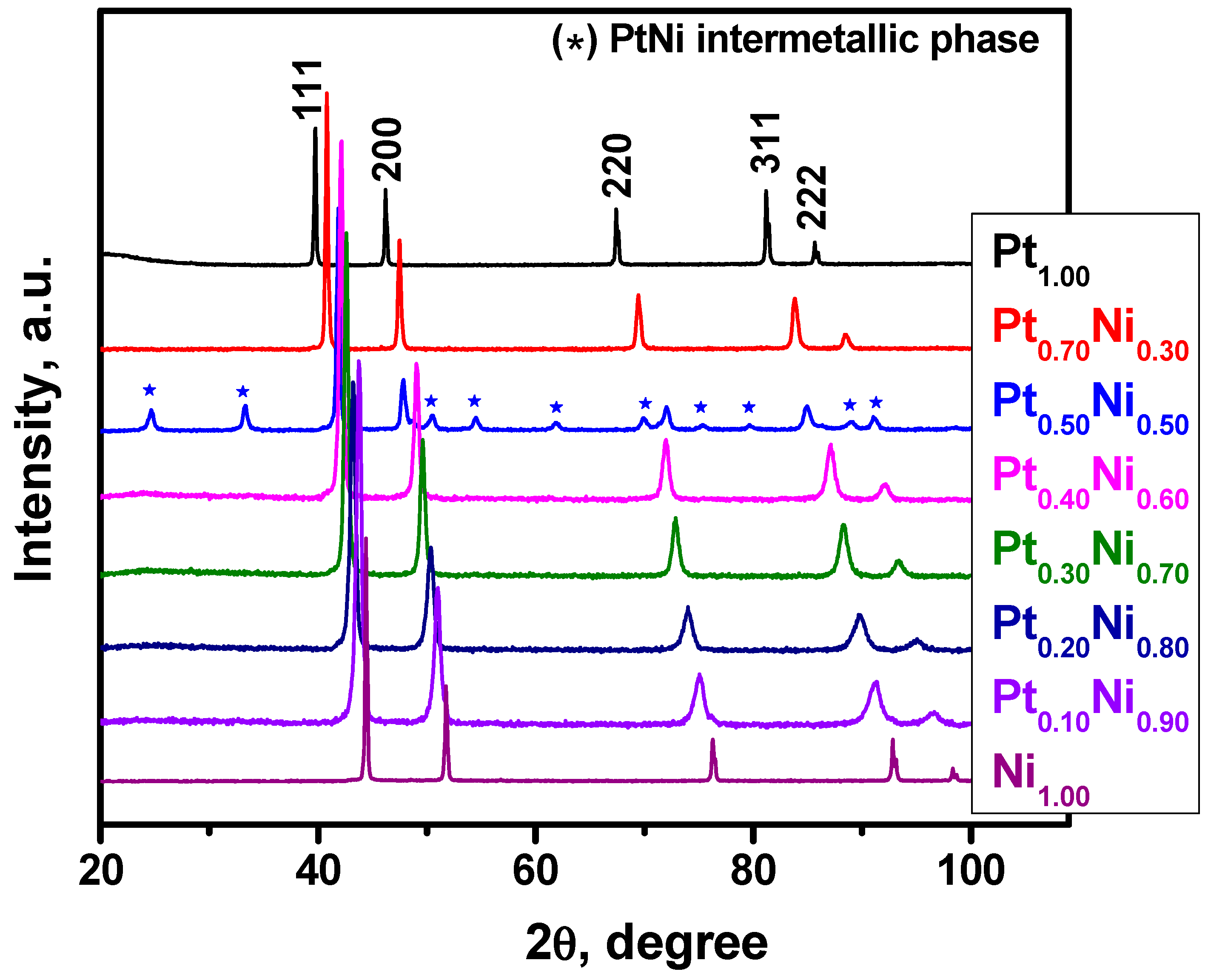
2.1. Synthesis and Characterization of Pt1−xNix Alloys

In the first stage of the work, the samples of Pt1−xNix porous alloys were synthesized by thermolysis of multicomponent precursors. These precursors represent micro-heterogeneous mixtures of the complex salts [Pt(NH3)4]Cl2·H2O and [Ni(NH3)6]Cl2 obtained by fast co-precipitation of an aqueous solution of the salts in cooled acetone. According to the element analysis data (Table 1), the compositions of the obtained alloys correspond to the ratio of metals specified during the synthesis of the precursors. Figure 1 shows the X-ray diffraction (XRD) patterns of the resulting Pt1−xNix alloys. The XRD pattern of the reference sample Pt1.00 is in full accord with information in the database for the Pt standard (space group Fm-3m, ICDD PDF-2 #4-802 [44]). The diffraction patterns of the samples with Ni content of 0–30 and 60–100 at.% show a set of reflections corresponding to the phase of the face-centered cubic (fcc) solid solution only. The reflections of the fcc phase present in the Pt1−xNix samples are shifted towards far 2θ angles concerning pure Pt. This indicates the incorporation of nickel atoms into the platinum lattice with the formation of the fcc alloy. The Pt0.50Ni0.50 sample contains a tetragonal phase with the PtNi intermetallic structure (space group P4/mmm, ICDD PDF-2 #65-2797 [44]) and a small amount of the fcc alloy phase. Thereby, the phase compositions of the synthesized Pt1−xNix samples are in good agreement with the phase diagram of the Pt-Ni system [45,46]. It should be noted that the composition of alloy phases determined from diffraction data using the calibration dependence of the specific atomic volume of the alloy on the Pt content [45] is consistent with the nominal metal content in the samples determined by the ICP-AES method (Table 1).
The morphology and secondary structure of the resulting alloys studied by SEM are demonstrated in Figure 2. According to the presented microscopic data, the Pt1−xNix samples have a characteristic porous structure, which is represented by irregularly shaped primary grains 100–150 nm in size. Primary particles are accreted with each other and connected by bridges of 75–100 nm in size (Figure 2a,c,e), thus forming a single spongy structure of the alloy. At the same time, certain differences can be noted for samples with a high content of Ni (more than 50 at.%). During reductive thermolysis, sintering of the particles with increased nickel content proceeds faster due to the higher diffusion rate of Ni atoms and is less refractory if compared to platinum. As a result, a porous structure built of primary particles of a larger size (up to 200 nm) is formed (Figure 2a–d). It should be emphasized that the observed morphology is typical for porous alloys obtained by the thermolysis of precursors [47,48]. Note that the specific surface area (SSA) of the initial microdispersed alloys is averaged to be ~10 m2/g.

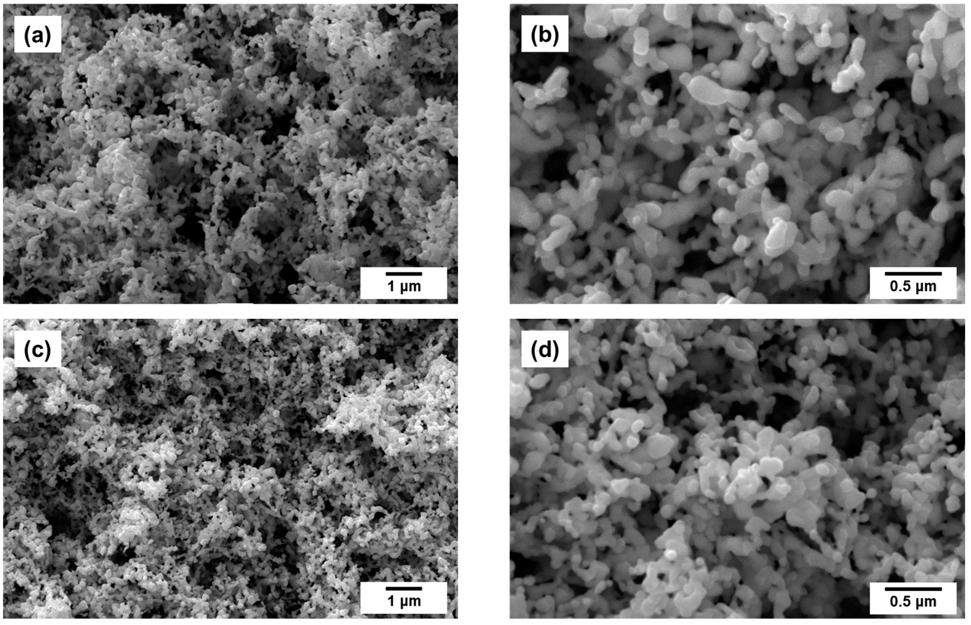
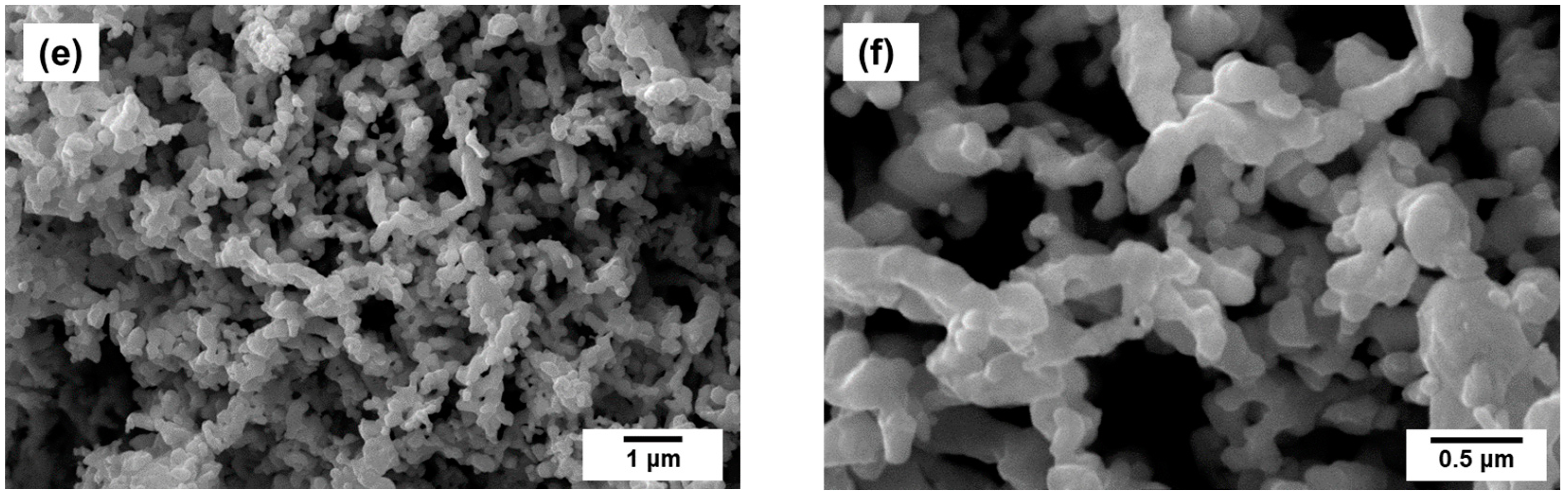
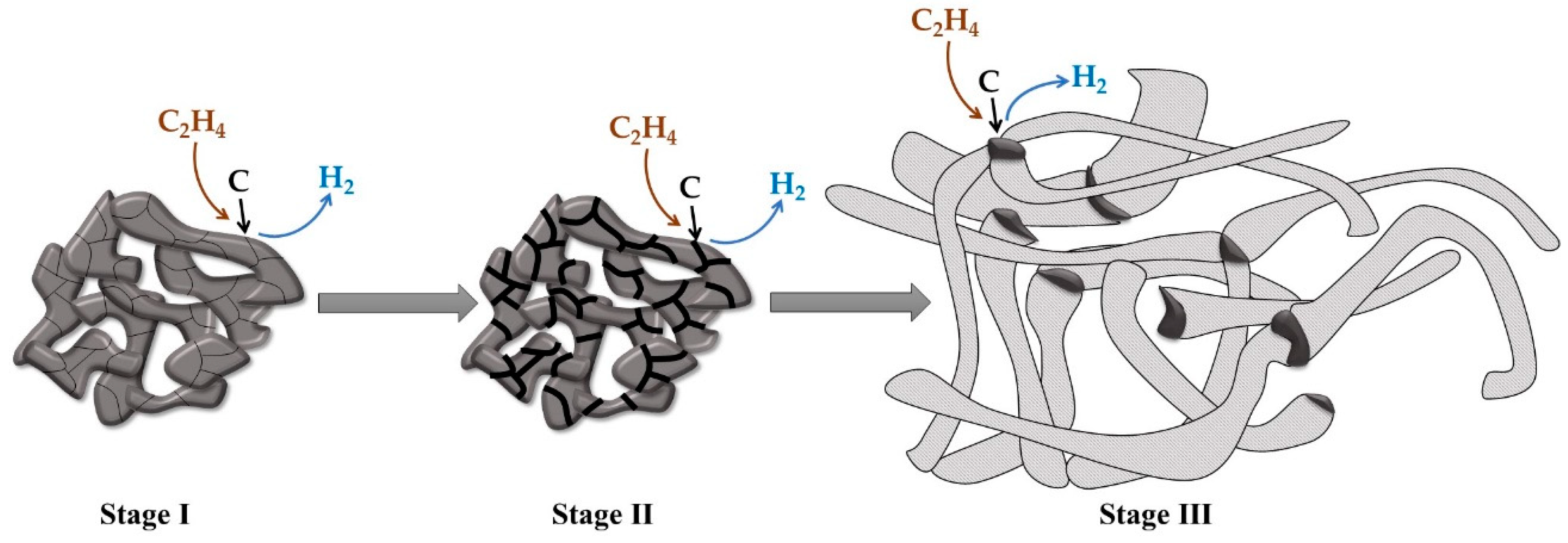
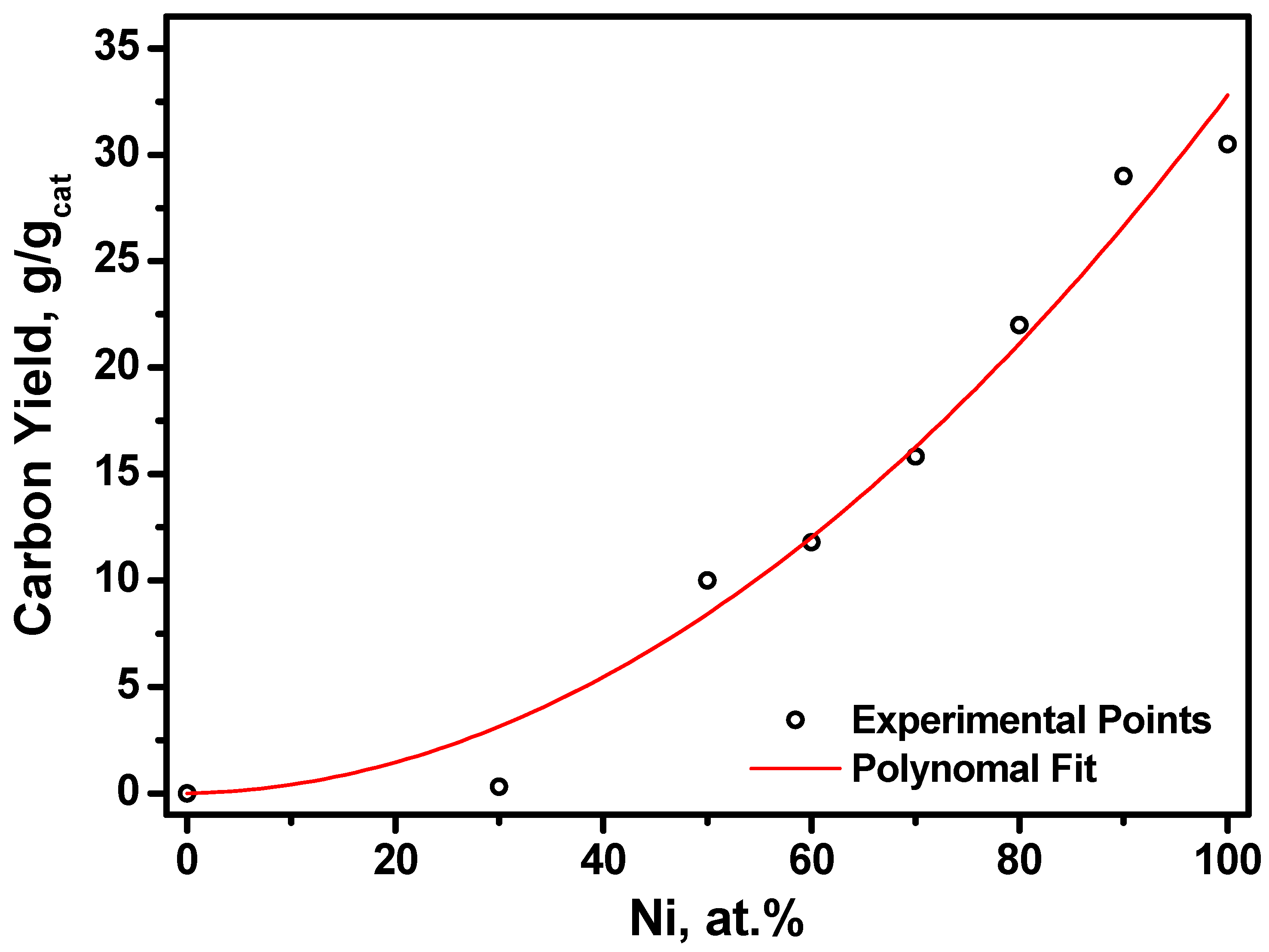
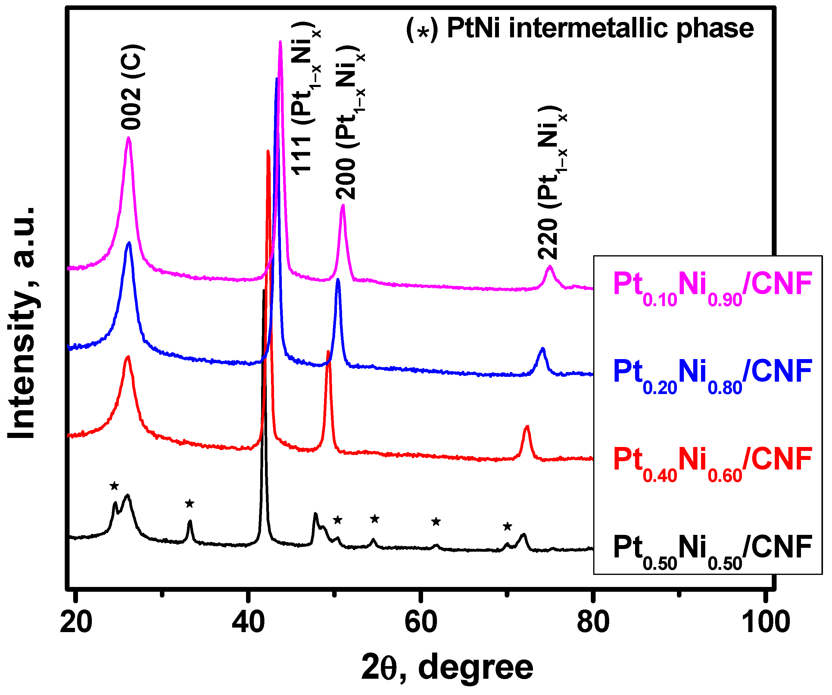
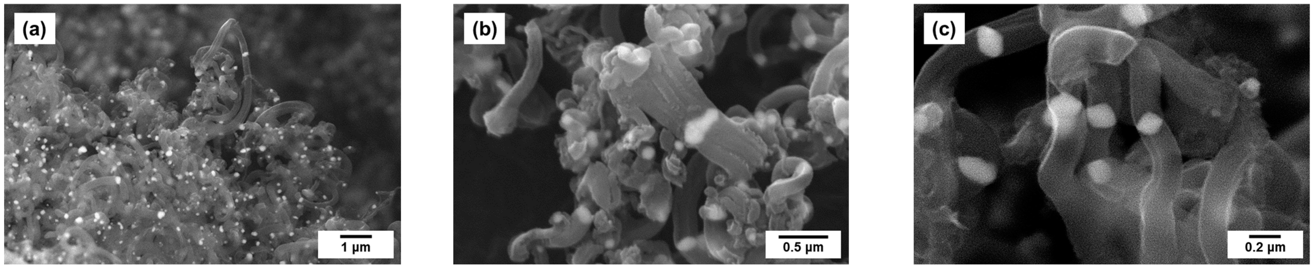
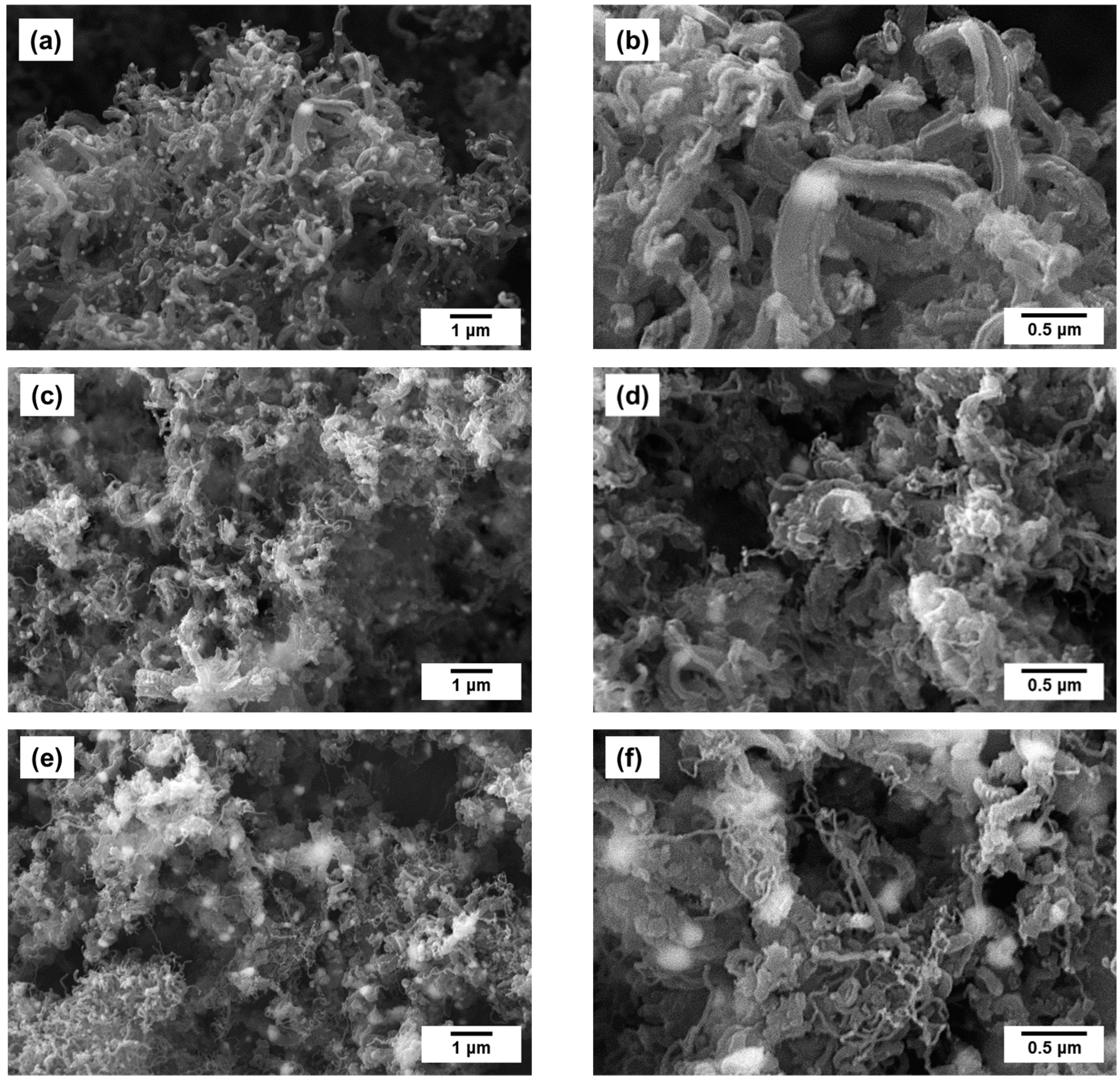
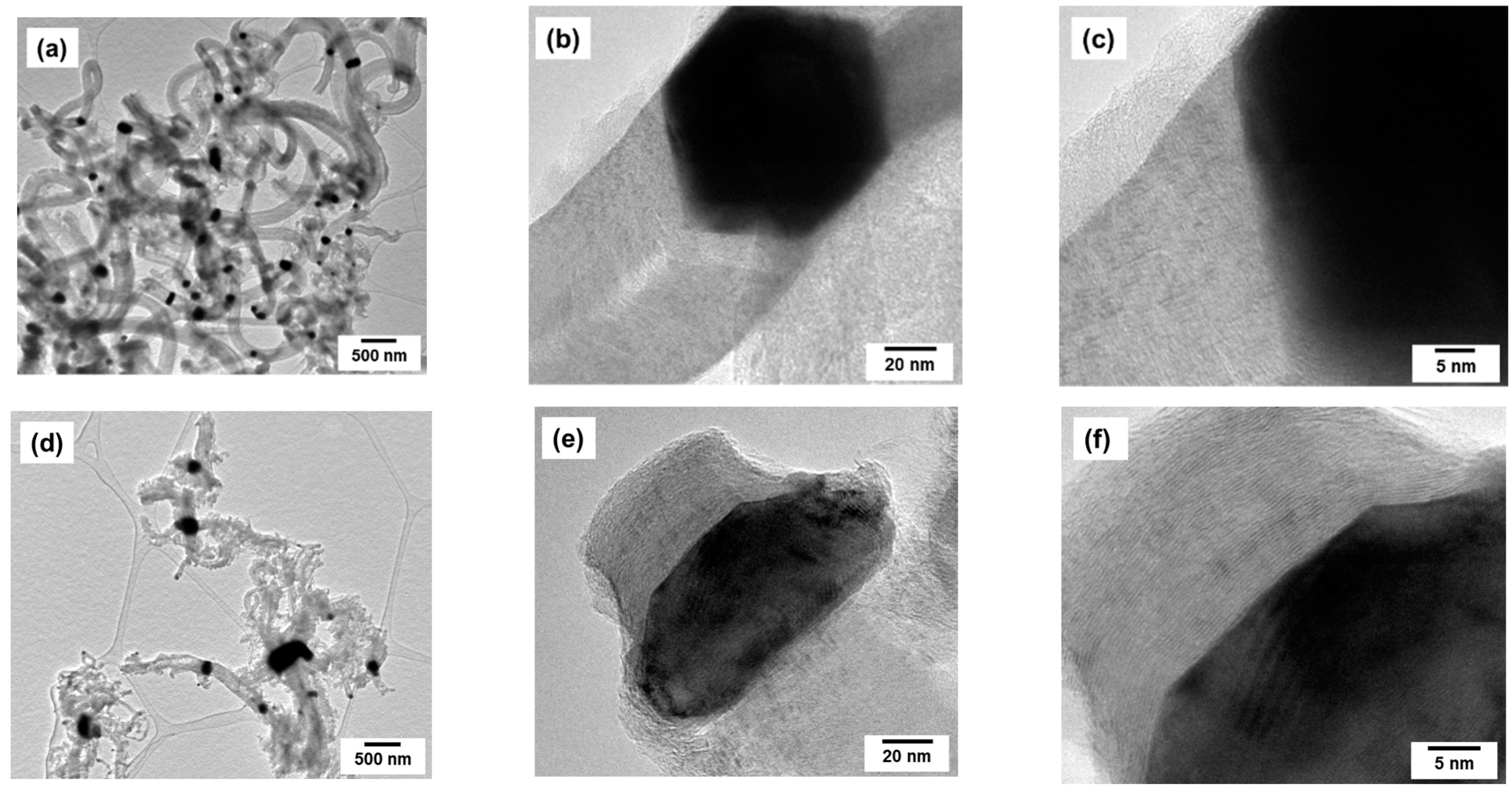
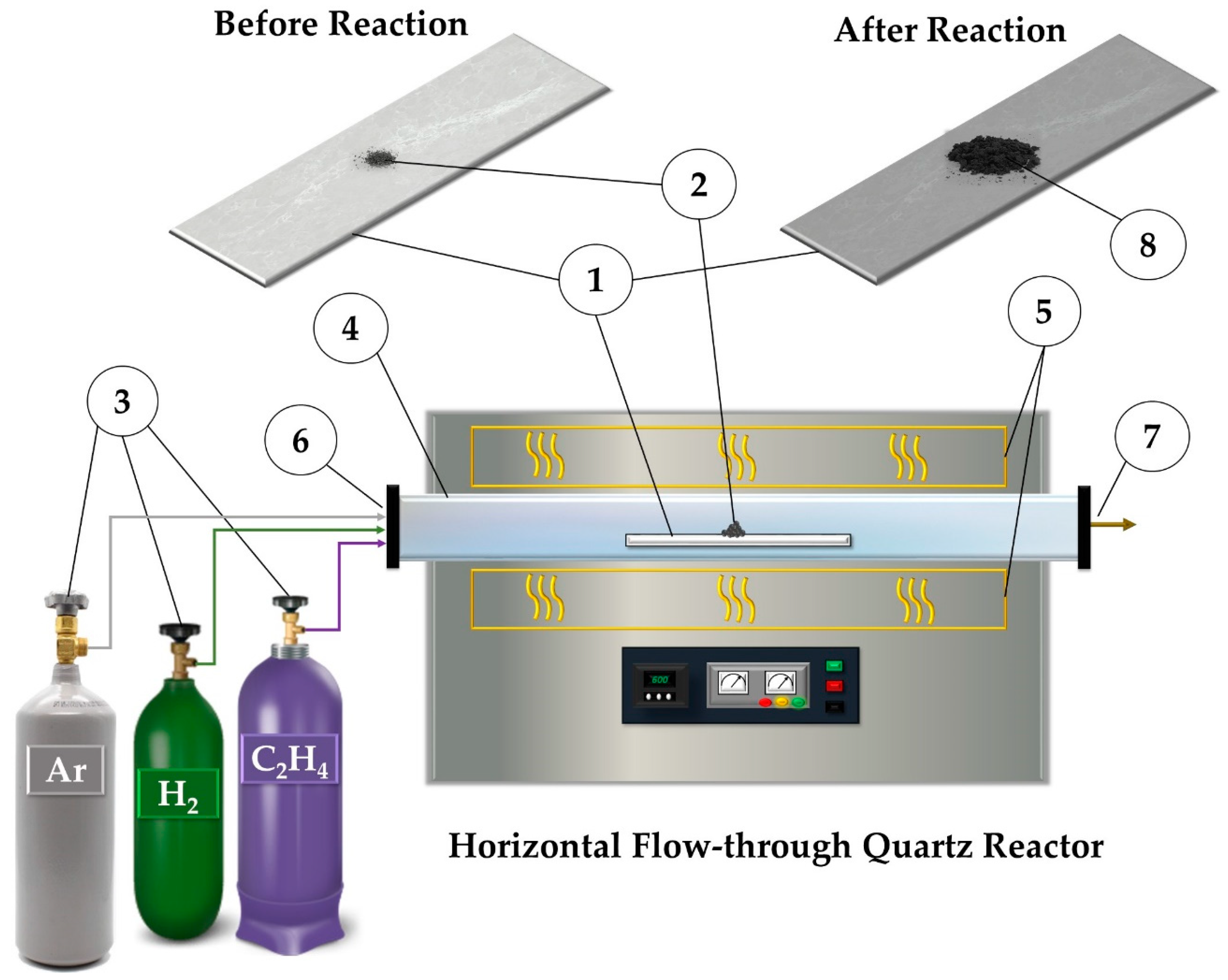
2.2. Preparation of Pt1−xNix/CNF Composites via Ethylene Decomposition over Pt1−xNix Alloys

In order to synthesize metal/CNF composite materials, catalytic decomposition of various hydrocarbons can be utilized [49,50]. In the present study, the synthesis of Pt1−xNix/CNF composites was carried out via ethylene decomposition over the prepared porous Pt1−xNix alloys. The choice of ethylene was due to its high tendency to form carbon under such reaction conditions. The overall reaction can be described by Equation (1):
C2H4 = 2C (CNF) + 2H2.
The process of catalytic decomposition of hydrocarbons with the CNF formation proceeds over the dispersed particles of metallic nickel and its alloys in accordance with the carbide cycle mechanism [51]. In turn, dispersed Ni-containing particles of submicron size emerge under the action of the reaction mixture as a result of the spontaneous disintegration of the initial alloy [52,53]. Such self-dispersion of the bulk metal or alloy is due to the process of carbon erosion (CE) (also known as metal dusting [41]). Figure 3 shows schematically the CE stage.
At the first stage of CE (Figure 3, stage I), ethylene molecules adsorb over the metal surface and decompose. This stage is accompanied by the transfer of carbon atoms into the alloy volume. An intensive dissolution of carbon in the metal grains results in the formation of a supersaturated carbon solution. At the next stage of the process (Figure 3, stage II), the nuclei of the graphite-like phase appear near the grain boundaries. Further accumulation of the graphite-like material leads to the disintegration of the alloy with the formation of dispersed particles catalyzing the growth of nanostructured carbon filaments (Figure 3, stage III). Depending on the reaction conditions, the alloy composition, and its dispersity (grain size), the duration of the CE process ranges from one minute [54] to several hours [53,55] or even months [56]. At the same time, the rate of the CE process is mostly determined by the nature of the catalyst precursor and its dispersity. Thus, for the items made of bulk metals and alloys (wire, foil, etc.), which possess a small specific surface, the CE process proceeds with the lowest rate [53,55,56]. Contrarily, the use of microdispersed alloys makes it possible to accelerate the disintegration process significantly [54], which is due to an increased contact area of the metal surface with a carbon-containing reaction medium.
At the end of the CE process (Figure 3, stage III), the complete disintegration of the initial alloy leads to the formation of a large number of active particles responsible for the subsequent growth of carbon filaments via the carbide cycle mechanism. The dispersed alloy particles obtained in such a way are embedded within the structure of CNF, which prevents their sintering or mechanical entrainment. The efficiency and success of the described approach in the targeted synthesis of carbon nanomaterials and metal–carbon composites have been well reported [40,57,58]. According to our previous evaluations [54], about 1013 active particles of submicron size (100–300 nm) are formed from 1 g of nickel-based alloy.
As shown above, the synthesized Pt1−xNix alloys are characterized by a well-developed porous structure, which makes it possible to provide an appropriate contact area of the alloy with the reaction mixture. Therefore, the process of controlled CE was chosen for the synthesis of Pt1−xNix/CNF composites.
In the next step of the research, the catalytic activity of Pt1−xNix alloys in the reaction of ethylene decomposition with the production of CNF was compared. In order to rank the samples by activity, the catalytic experiments were carried out with the same duration of 15 min. Each sample of the alloys was examined twice to check the reproducibility of the results. The obtained dependence of the carbon yield (YCNF) in the ethylene decomposition reaction on the Ni content is presented in Figure 4.
As it follows from experimental data, pure Pt is not active in the ethylene decomposition reaction (~0 g/gcat), which is quite expected [40]. As a result of the interaction of the Pt1.00 sample with ethylene, only a small layer of non-catalytic carbon is formed on its surface [40]. The inertness of platinum can be attributed to the fact that, at the reaction temperature of 600 °C, Pt does not form solid solutions with carbon [59]. Thereby, the bulk Pt does not undergo disintegration via the CE route. The addition of 30 at.% Ni to platinum does not change the situation, and the carbon yield value remains close to 0 g/gcat. Comparing the obtained data with those for Pt1−xCox bimetallic system [40], it can be noted that the Pt0.75Co0.25 sample with the same content of base metal also exhibited low activity (the carbon yield did not exceed 1–2 g/gcat).
As can be seen from Figure 4, a further increase in the Ni concentration in the Pt1−xNix alloy (up to 50 at.% and above) improves the catalytic activity significantly (the carbon yield exceeds 10 g/gcat). The highest carbon yield of 31 g/gcat was achieved over the pure Ni sample (Ni1.00). This result is also not surprising. As is known, Ni belongs to the iron subgroup (Fe, Co, Ni). All these metals possess high activity in the process under study. They are traditionally used as components of the catalysts for the synthesis of carbon nanostructures by the CCVD method [60].
According to the low-temperature N2 adsorption–desorption data, the obtained Pt1−xNix/CNF composites are characterized by high SSA values. Moreover, an increase in the Ni content in the alloy composition from 30 to 70 at.% leads to a rise in the SSA values from 100 to 147 m2/g.
Then, a set of Pt1−xNix/CNF composite samples for electrocatalytic testing in the hydrogen evolution reaction (HER) was prepared. The duration of the CCVD procedures was varied in a range from 3 to 15 min in order to provide the carbon yield of ~4 g/gcat. At this value, the content of metals in the Pt1−xNix/CNF composites corresponds to 20 wt.%. In practice, according to the element analysis data (AES), the total content of metals in the composition of the synthesized composite samples is in the range of 18–22 wt.%. Table 2 summarizes the synthesis parameters and the main characteristics of the prepared Pt1-xNix/CNF composite samples.
The phase composition of the prepared samples of Pt1−xNix/CNF (x = 0.50–0.90) composites was studied by XRD (Figure 5). In most cases, the XRD patterns show reflections corresponding to Pt1−xNix alloys with the fcc structure. For the Pt0.50Ni0.50/CNF sample, the PtNi intermetallic compound structure was identified. As follows from Table 2, the lattice parameters of solid solutions before and after the reaction with ethylene are the same within the error of determination. Thus, the composition of the alloy particles in the composite samples corresponds to that of the initial alloys. The width of the reflections of solid solutions in the Pt1−xNix/CNF samples slightly increased compared to the width of the reflections of the original porous alloys. This could be caused by the incorporation of carbon into the structure of the alloy particles and the occurrence of defects, which was previously observed on Pt-Ni alloys for the reaction of 1,2-dichloroethane decomposition [42]. Additionally, for all samples, the presence of a characteristic broadened peak at 2θ = 26°, corresponding to the (002) reflection of a graphite-like material, is noted.
Electron microscopy techniques, SEM and TEM, were used to study the morphology and structural features of the prepared Pt1−xNix/CNF composite samples in detail. According to the data obtained (Figure 6 and Figure 7), the carbon product is represented by a set of filaments of submicron diameter. Based on the array of recorded images, it can be concluded that the dispersed submicron particles were formed as a result of the disintegration of the initial alloy. These particles are clearly seen in the back-scattered electron mode (Figure 6). At a higher magnification (Figure 6b,c), it becomes evident that these metal particles behave as catalytic centers for the growth of carbon filaments. The length of the formed fibers ranges from 1 to 10 μm. Additionally, it is worth mentioning that, in certain areas of the catalyst, the disintegration of the alloy was not complete. Thus, an active particle being in the process of fragmentation (separation into several independent centers of CNF growth) is observable in Figure 6b. It can be seen that individual sections on the surface of this particle work independently, which leads to the separation of the growing carbon filament into several filaments of smaller diameters. With an increase in the exposure time, it can be expected that the complete disintegration of this particle will lead to the formation of several independent centers of CNF growth [61].
It should be noted that the catalytic particles formed via the disintegration of alloys have a predominantly symmetric polyhedron shape with a very distinct faceting (Figure 6c). The observed particle shape is one of the preferred options described earlier in [51,62]. The size of dispersed metal particles averages 150 nm (Figure 6b,c) and coincides with the diameter of the growing carbon fibers (Figure 6c). According to the estimations made, on average, about 4 × 10¹³ catalytic particles of the indicated size are formed from 1 g of the alloy.
An analysis of the morphology of CNF samples obtained on alloys with a high Ni content (60 at.% and above) shows that, in addition to fibers with a diameter of 0.1 to 0.25 μm, the composition of the carbon product also contains thinner fibers, the diameter of which does not exceed several tens of nanometers (Figure 7b,c,f). The appearance of such nanofibers in the composition of the CNF sample is associated with the occurrence of the process of secondary disintegration of submicron catalytic particles [53]. It should be noted that the probability of secondary fragmentation of alloy particles rises with an increase in the Ni concentration in the composition of the initial alloy, as evidenced by a noticeable increase in the proportion of thin carbon filaments in the carbon nanomaterial.
Figure 8 shows the TEM results for the Pt0.50Ni0.50/CNF and Pt0.80Ni0.20/CNF samples. The data obtained are consistent with the SEM data. The length of carbon filaments in the composition of the Pt0.50Ni0.50/CNF sample does not exceed 10 µm, and the diameter is in a range from 0.1 to 0.25 µm (Figure 8a). As is also seen, the formed alloy particles are predominantly polyhedron-shaped and clear-cut (Figure 8b,c). At the same time, in the composition of the composite obtained on the Pt0.20Ni0.80 alloy, the carbon filaments are of a noticeably shorter length (no more than 5 μm) and possess a disordered structure (Figure 8d). The presence of large metal particles within the composition of the Pt0.80Ni0.20/CNF sample indicates that the disintegration process is incomplete in this case (Figure 8d).
Comparing the structural features of carbon filaments observed for Pt0.50Ni0.50/CNF and Pt0.20Ni0.80/CNF alloys, it should be noted that in the first case (Figure 8b,c), the grown filaments are of a typical coaxial-conical structure (fishbone) [63]. An increase in the Ni concentration in the alloy from 50 to 80 at.% leads to a transformation of the geometry of catalytic particles with the appearance of faces, on which the growth of fibers of a stacked structure occurs. The structure of these CNFs is known as a “pile of books” or “pile of plates” (Figure 8e,f) [64,65]. For the carbon nanofibers obtained on the Pt0.50Ni0.50 alloy, the distance between graphene layers is 0.355–0.360 nm, while this value is 0.348–0.355 nm for the CNF samples synthesized using the Pt0.20Ni0.80 alloy. Thus, with an increase in the Ni content in the composition of the alloy, a decrease in the distance between graphene layers in the structure of carbon nanofibers is observed. Nevertheless, in both cases, the measured interplanar spacing is somewhat larger than that of crystalline graphite (0.337 nm).
Based on TEM data for all the studied samples, the sizes of the alloy particles correlate with the diameter of the filaments (Figure 8a,d), which is in good agreement with the data obtained by the SEM method. According to EDX data, the composition of bimetallic particles in the Pt1−xNix/CNF composites coincides with the ratio of Pt and Ni in the original alloy (Table 3).
Thus, the decomposition of ethylene is accompanied by the disintegration of the alloy with the formation of dispersed alloy particles that catalyze the growth of carbon nanofibers. When carbon yield corresponds to ~4 g/gcat, the content of the alloy in the composition of the composite varies near the value of 20 wt.%. In such a mode of controlled carbon erosion of Pt1−xNix alloys, a series of Pt1−xNix/CNF composites was successfully synthesized. The Pt-Ni particles of a desired ratio are strongly anchored within the resulting Pt1−xNix/CNF composites. Such materials can be considered catalysts with improved resistance toward deactivation caused by the sintering of the particles.
It is worth noting that the surface of the alloy particles embedded with the CNF structure is accessible for the reagents, which makes it possible to use these composites as catalysts for various electrochemical reactions.

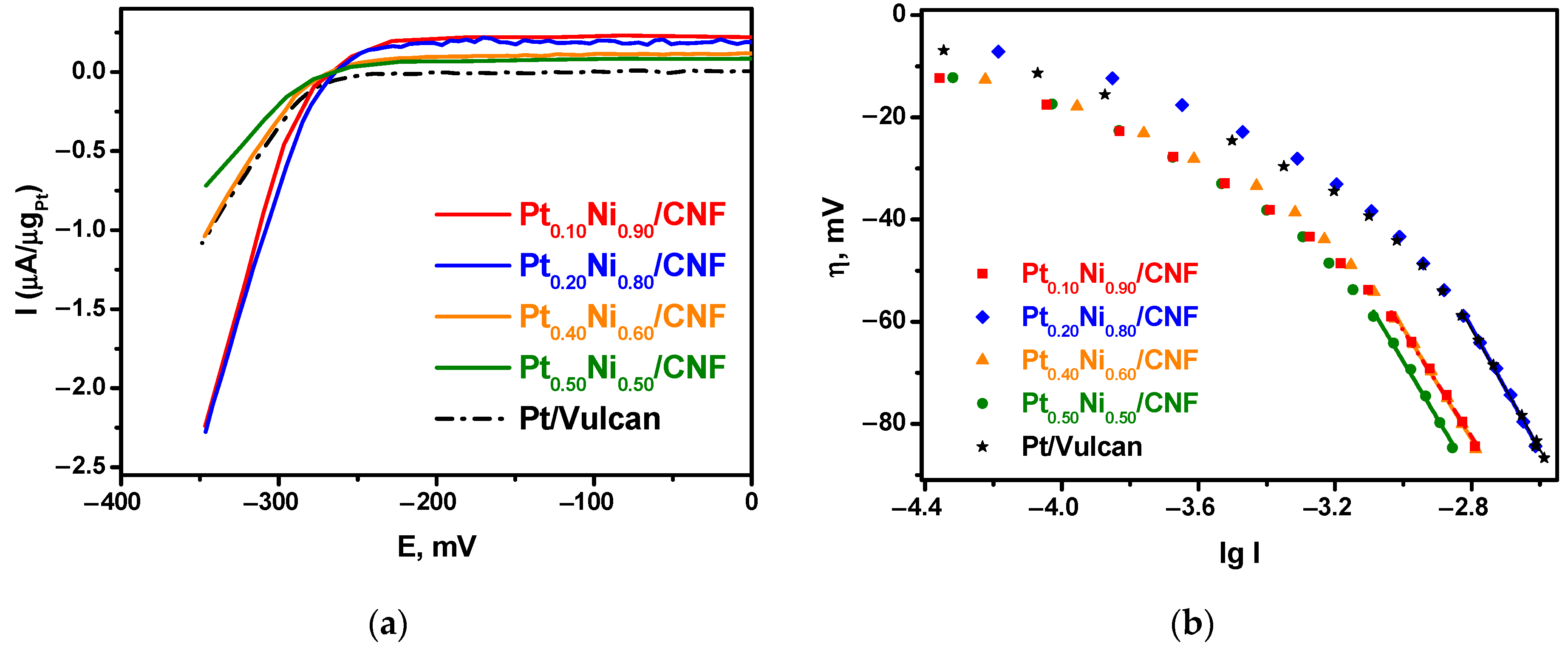
2.3. Electrocatalytic Testing of Pt1−xNix/CNF Composites

The electrocatalytic properties of the samples of Pt1−xNix/CNF composites were studied in the hydrogen evolution reaction (HER) in 0.100 M H2SO4. The results of the experiments performed make it possible to evaluate the electrochemical activity of alloyed samples in comparison with a commercial sample (Pt/Vulcan) containing 20 wt.% Pt on a Vulcan XC-72R carbon support. Figure 9a shows current–voltage curves obtained with a linear potential sweep. The experimentally measured current is normalized to the Pt content in the samples. It can be seen that, for all samples, a significant increase in the cathode current is observed at potentials below –220 mV. The Pt0.10Ni0.90/CNF and Pt0.20Ni0.80/CNF samples exhibit the highest activity, which is twice that of the commercial Pt/Vulcan sample. Pt0.60Ni0.40/CNF showed lower activity comparable with that of the Pt/Vulcan sample. The Pt0.50Ni0.50/CNF sample was the least active.
The Tafel dependences (Equation (2)) of hydrogen reduction processes on various samples are shown in Figure 9b.
η = a + b∙lg I,
where η is the overvoltage, mV; I is the current, mA; a and b are the coefficients.
The coefficients a and b, determined by linear approximation of the graphs in the high overvoltage region, are presented in Table 4. The exchange current densities i0 in this region for different samples have comparable values. The values of the Tafel slopes b close to 120 mV in the overvoltage region above 60 mV allow us to conclude that the rate-determining stage of the hydrogen reduction process is the same for all samples and is determined by the slow desorption of hydrogen atoms from the electrode surface [66].
The results of the electrochemical impedance spectroscopy analysis are presented in the Supplementary Information (Figure S1). This method was used to obtain the information concerning the kinetics of electrochemical processes over Pt1−xNix/CNF composites. Comparison of the presented Nyquist plots testifies that the charge transfer resistance (RCT) for the Pt1−xNix/CNF samples is somewhat lower than that for the commercial sample (Pt/Vulcan). The estimation of the radii values from the Nyquist plots gives R = 22.88 Ohm for Pt0.20Ni0.80/CNF, R = 19.9 Ohm for Pt0.10Ni0.90/CNF, and R = 25.5 Ohm for Pt/Vulcan. As is known, the electrocatalytic activity is connected with the RCT value. Thereby, the resulting Pt1−xNix/CNF catalysts are more active in the electrochemical hydrogen evolution reaction than the Pt/Vulcan reference sample. The data obtained expand the possibilities of using the solid-state reaction products of the hydrocarbon decomposition over porous alloys for electrocatalytic applications. Reducing the platinum loading in the catalyst composition allows for reducing the cost while maintaining its efficiency.

3. Materials and Methods

3.1. Materials and Chemicals

[Pt(NH3)4]Cl2·H2O (Aurat, Moscow, Russia), [Ni(NH3)6]Cl2 (synthesized according to a well-known method [67]), ammonia (puriss. spec.), acetone (puriss. spec.), and helium (puriss. spec.) were used to prepare Pt1−xNix alloys. Hydrogen was obtained using a Tsvetkhrom-6 generator (Tsvetkhrom, Dzerzhinsk, Russia). Hydrochloric acid (puriss. spec.) and nitric acid (puriss. spec.) were used to prepare the samples for elemental analysis.
High-purity ethylene purchased from Nizhnekamskneftekhim (Nizhnekamsk, Russia), high-purity argon, and hydrogen were used for the synthesis of Pt1−xNix/CNF composites.
Bidistilled water, isopropanol (puriss. spec.), Nafion (Sigma-Aldrich, Burlington, MA, USA), high-purity argon, and sulfuric acid (puriss. spec.) were used in the electrochemical experiments. The reference sample, 20% Pt/Vulcan XC-72R, was purchased from Sigma-Aldrich (Burlington, MA, USA).

3.2. Synthesis of Pt1−xNix Alloys

The samples of initial alloys were obtained by thermolysis of specially prepared precursors, which were micro-heterogeneous mixtures of platinum and nickel amino complexes. The complex salts [Pt(NH3)4]Cl2·H2O and [Ni(NH3)6]Cl2 were used as initial metal compounds. Weighed portions of complex compounds taken in the required ratios (500 mg in total) were dissolved in 4–6 mL of ~10% aqueous ammonia solution. The resulting solution was quickly added to 100–120 mL of chilled acetone with vigorous stirring. The precipitate was filtered out, washed with acetone, and dried in air. The thermolysis procedure of the resulting precursor was carried out in a quartz reactor in an H2 atmosphere at 600 °C for 1 h. Then, the sample was cooled to room temperature in a helium flow. Thermolysis of the precursor containing 50 at.% Ni was carried out for 3 h to obtain alloy particles with the crystal structure of the PtNi intermetallic compound. Monometallic reference samples, Pt1.00 and Ni1.00, were also synthesized using the same procedures.

3.3. Synthesis of Pt1−xNix/CNF Composites

Synthesis of Pt1−xNix/CNF composites was performed in a horizontal quartz flow reactor, shown in Figure 10. A specimen of the alloy (catalyst precursor) was placed on a quartz plate in an amount of 25.00 ± 0.02 mg. Then, the plate was loaded into a reactor (Zhengzhou Brother Furnace Co., Ltd., Zhengzhou, Henan, China) in a horizontal position. Note that the furnace of the reactor is characterized by a uniform temperature profile along its length (±5 °C). Next, the sample was heated in an inert gas (Ar) flow to the reaction temperature (600 °C), after which the sample was preliminarily reduced in an H2 flow (for 15 min) in order to remove the surface oxide film. Then, at the same temperature, the reactor was fed with a reaction mixture containing 40 vol.% C2H4, 20 vol.% H2, and 40 vol.% Ar. The feed rate of the reaction mixture was 54 L/h. Upon completion of the reaction, the obtained Pt1−xNix/CNF composites were cooled in an argon flow and then unloaded from the reactor. After weighing the sample, the carbon yield (YCNF, g/gcat) was calculated. Each experiment was repeated at least two times to refine the data on the catalytic activity of the alloys. The measurement error for the calculated carbon yield did not exceed 10%.

3.4. Characterization of Materials

The elemental composition of the Pt1−xNix alloys was determined by inductively coupled plasma atomic emission spectrometry (ICP-AES) on a Thermo Scientific iCAP-6500 spectrometer (Thermo Fisher Scientific, Waltham, MA, USA). Before analysis, the samples were dissolved in aqua regia at heating. The relative standard deviation of the determination of metals was 0.03.
Powder X-ray diffraction (XRD) analysis of the samples was carried out on a Shimadzu XRD-7000 diffractometer (Shimadzu Corporation, Tokyo, Japan) at CuKα radiation, using a graphite monochromator. The patterns were recorded within a 2θ angle range of 20–100° with a step of 0.05°.
The specific surface area values were measured by nitrogen adsorption at 77 K. The isotherms were recorded using an automatic adsorption analyzer 3P sync 220A (3P INSTRUMENTS, Odelzhausen, Germany). Before the measurements, all samples were degassed in a vacuum of less than 1 Pa at 300 °C for 3 h.
The identification of the crystalline phases was based on the ICDD powder diffraction file cards [44]. The unit cell parameters were determined by the full profile method using the specified software [68]. The composition of the phases in the alloys was determined from diffraction data using the calibration dependence of the specific atomic volume of the alloy on the composition in accordance with Equation (3) [45].
v = Vcells/Zat,
where v is the specific atomic volume of the alloy (the average volume occupied by one metal atom), Vcell is the volume of the crystalline cell of the alloy, and Zat is the number of metal atoms per cell.
The study of the secondary structure and morphology of the samples of alloys and carbon material was carried out by scanning electron microscopy (SEM) on a JSM-5100LV microscope (JEOL Ltd., Tokyo, Japan) equipped with an EX-23000BU EMF spectrometer (SPECTRO Analytical Instruments, Kleve, German). The working voltage of the microscope was 15 kV, and the magnification was in a range of 1000–100,000×.
The study of the primary structure and composition of carbon product samples was performed by transmission electron microscopy (TEM) on a JEOL JEM 2100 instrument (JEOL Ltd., Tokyo, Japan) equipped with an INCA-250 energy dispersive x-ray spectrometer (Oxford Instruments, Abingdon, Oxfordshire, UK). The accelerating voltage was 200 kV, and the resolution was 0.14 nm. The samples were applied to perforated carbon films fixed on a copper grid. Computer processing of the obtained EM images and measuring the distances between the layers of graphene in the structure of carbon nanofibers were performed using the Digital Micrograph “Gatan” (Pleasanton, CA, USA).

3.5. Electrochemical Testing of Pt1−xNix/CNF Composites

The synthesized samples of Pt1−xNix/CNF composites were tested in the hydrogen evolution reaction (HER). A glassy carbon electrode (Sigradur G brand, HTW Hochtemperatur-Werkstoff GmbH, Thierhaupten, Germany) was used as a working electrode (working surface diameter 5.00 mm, geometric working area 0.196 cm2). To modify the electrode with Pt1−xNix/CNF composite samples, a suspension of the following composition was prepared: 5.00 mg of the sample, 1000 µL of isopropyl alcohol, 900 µL of bidistilled water, and 100 µL of 10% Nafion. This mixture was processed in an ultrasonic bath (Vilitek VBS-2DS, Vilitek, Moscow, Russia) at a frequency of 40 kHz (15 min), and then at a frequency of 28 kHz (15 min). After that, using a Lenpipet Digital Micro 0.5–10 µL automatic pipette (Lenpipet, Moscow, Russia), 5.00 µL of the suspension was applied to the prepared glassy carbon electrode and dried for 15 min in an argon flow.
The electrochemical measurements were carried out on a P-20X8 potentiostat (Elins, Novosibirsk, Russia) in a homemade three-electrode cell at room temperature. A platinum grid was used as a counter electrode. The working solution and space for the counter electrode were separated by a filter with a pore size of 0.4 μm (Sartorius AG, Göttingen, Germany). The reference electrode was a silver chloride electrode Ag | AgCl | 3.5 M KCl (Izmeritelnaya Tehnika, Moscow, Russia) with a potential of 208 mV regarding the normal hydrogen electrode. The reference electrode was connected to the working solution using a Luggin capillary filled with a working electrolyte. To study the hydrogen evolution reaction (HER), the cell was filled with a solution of 0.1 M H2SO4 (approximately 50 mL), and the solution was purged with argon for 20 min. After that, a cyclic potential sweep was performed: 50 cycles at 50 mV/s in a range of −350–1000 mV to standardize the surface of the working electrode. Then, the solution was purged with hydrogen for 20 min, and voltammetric measurements were performed with a linear potential sweep in the range from 500 to –350 mV at a potential sweep rate of 10 mV/s. During the experiments, the working solution was stirred on an IKA Topolino (IKA-Werke GmbH & Co. KG, Staufen, Germany) magnetic stirrer.
The electrochemical impedance spectroscopy measurements were carried out on a SP-300 Potentiostat (Bio-Logic SAS, Seyssinet-Pariset, France). The EIS measurements were performed over a frequency range of 1 Hz to ~1 MHz at a perturbation amplitude of 5 mV. Nyquist plots of the catalysts in 0.1 M H2SO4 solution were obtained at a potential of −0.200 V vs. silver chloride electrode Ag|AgCl|3.5 M KCl.

4. Conclusions

A series of porous Pt1−xNix alloys were synthesized by thermolysis of multicomponent precursors in a wide range of concentrations (x = 0.00–1.00). The catalytic activity of the obtained alloys in the reaction of ethylene decomposition with the formation of CNF was studied. It has been established that the addition of Ni to Pt increases the activity of the alloy in terms of carbon yield by 10–30 times. Thus, the highest carbon yield of about 30 g/gcat in the course of ethylene decomposition for 15 min was observed for the samples Pt0.10Ni0.90 and Ni1.00. It was demonstrated that Pt1−xNix alloys could be successfully used as precursors for obtaining metal–carbon composites.
Using the prepared Pt1−xNix alloys of desired compositions, the Pt1−xNix/CNF composites containing 20 wt.% of the alloy were synthesized via ethylene decomposition performed in a mode of controlled carbon erosion. The resulting Pt1−xNix/CNF samples represent submicron alloy particles embedded within the structure of carbon nanofibers. It was shown that the ratio of metals in these alloy particles corresponds to that in the initial alloys. The prepared composites were tested in the electrochemical hydrogen evolution reaction. The Pt0.10Ni0.90/CNF and Pt0.20Ni0.80/CNF samples demonstrate the highest activity in this process, which exceeds the performance of the commercial 20 wt.% Pt/Vulcan XC-72R sample by two times. Thus, the proposed approach to the preparation of metal–carbon composite catalysts, in which platinum is replaced by cheaper nickel by up to 80%, provides the possibility of significantly reducing the cost of implementing practically important electrochemical processes.

Supplementary Materials

The following supporting information can be downloaded at: https://www.mdpi.com/article/10.3390/catal13030599/s1, Table S1: Carbon-based Pt-Ni composites used for electrochemical applications; Figure S1: Electrochemical impedance spectroscopy analysis data (Nyquist plots) for the samples of Pt1−xNix/CNF composites.

Author Contributions

Conceptualization, I.V.M., A.A.P. and S.D.A.; methodology, A.A.P., A.D.V., Y.I.B., P.E.P. and M.V.T.; investigation, Y.I.B., A.A.P., M.V.T. and P.E.P.; writing—original draft preparation, S.D.A., A.D.V., P.E.P. and A.A.P.; writing—review and editing, I.V.M., Y.V.S. and A.A.V.; visualization, S.D.A., A.D.V. and A.A.P.; supervision, Y.V.S., A.A.V. and I.V.M.; funding acquisition, Y.V.S. and I.V.M. All authors have read and agreed to the published version of the manuscript.

Funding

This work was financially supported by the Russian Science Foundation (project No. 21-13-00414, https://rscf.ru/project/21-13-00414/, NIIC SB RAS). The catalytic experiments were supported by the Ministry of Science and Higher Education of the Russian Federation (project No. AAAA-A21-121011390054-1).

Data Availability Statement

Data is contained within the article.

Acknowledgments

Analysis of the physicochemical properties of the samples was performed using the equipment of the “National Center for Catalyst Research” and the Omsk Regional Center for Collective Use of the Siberian Branch of the Russian Academy of Sciences. The authors are grateful to Alexandra Serkova for her assistance in the SEM studies, Alfiya Tsygankova for performing element analysis by ICP-AES, and Danil Shivtsov for his help with nitrogen adsorption measurements.

Conflicts of Interest

The authors declare no conflict of interest.

References

  1. Carrette, L.; Friedrich, K.A.; Stimming, U. Fuel Cells: Principles, Types, Fuels, and Applications. ChemPhysChem 2000, 1, 162–193. [Google Scholar] [CrossRef] [PubMed]
  2. Lucia, U. Overview on fuel cells. Renew. Sustain. Energy Rev. 2014, 30, 164–169. [Google Scholar] [CrossRef]
  3. Xiao, F.; Wang, Y.-C.; Wu, Z.-P.; Chen, G.; Yang, F.; Zhu, S.; Siddharth, K.; Kong, Z.; Lu, A.; Li, J.-C.; et al. Recent advances in electrocatalysts for proton exchange membrane fuel cells and alkaline membrane fuel cells. Adv. Mater. 2021, 33, 2006292. [Google Scholar] [CrossRef]
  4. Lü, X.; Qu, Y.; Wang, Y.; Qin, C.; Liu, G. A comprehensive review on hybrid power system for PEMFC-HEV: Issues and strategies. Energy Convers. Manag. 2018, 171, 1273–1291. [Google Scholar] [CrossRef]
  5. Lasia, A. Mechanism and kinetics of the hydrogen evolution reaction. Int. J. Hydrogen Energy 2019, 44, 19484–19518. [Google Scholar] [CrossRef]
  6. Safizadeh, F.; Ghali, E.; Houlachi, G. Electrocatalysis developments for hydrogen evolution reaction in alkaline solutions—A Review. Int. J. Hydrog. Energy 2015, 40, 256–274. [Google Scholar] [CrossRef]
  7. Vesborg, P.C.K.; Seger, B.; Chorkendorff, I. Recent Development in Hydrogen Evolution Reaction Catalysts and Their Practical Implementation. J. Phys. Chem. Lett. 2015, 6, 951–957. [Google Scholar] [CrossRef]
  8. Eftekhari, A. Electrocatalysts for hydrogen evolution reaction. Int. J. Hydrog. Energy 2017, 42, 11053–11077. [Google Scholar] [CrossRef]
  9. Stacy, J.; Regmi, Y.N.; Leonard, B.; Fan, M. The recent progress and future of oxygen reduction reaction catalysis: A review. Renew. Sustain. Energy Rev. 2017, 69, 401–414. [Google Scholar] [CrossRef] [Green Version]
  10. Sealy, C. The problem with platinum. Mater. Today 2008, 11, 65–68. [Google Scholar] [CrossRef]
  11. Hussain, S.; Erikson, H.; Kongi, N.; Sarapuu, A.; Solla-Gull, J.; Maia, G.; Kannan, A.M.; Alonso-Vante, N.; Tammeveski, K. Oxygen reduction reaction on nanostructured Pt-based electrocatalysts: A review. Int. J. Hydrog. Energy 2020, 45, 31775–31797. [Google Scholar] [CrossRef]
  12. Ren, X.; Lv, Q.; Liu, L.; Liu, B.; Wang, Y.; Liu, A.; Wu, G. Current progress of Pt and Pt-based electrocatalysts used for fuel cells. Sustain. Energy Fuels 2020, 4, 15. [Google Scholar] [CrossRef]
  13. Watanabe, M.; Igarashi, H.; Fujino, T. Design of CO tolerant anode catalysts for polymer electrolyte fuel cell. Electrochemistry 1999, 67, 1194–1196. [Google Scholar] [CrossRef] [Green Version]
  14. Liu, J.; Lan, J.; Yang, L.; Wang, F.; Yin, J. PtM (M = Fe, Co, Ni) Bimetallic Nanoclusters as Active, Methanol-Tolerant, and Stable Catalysts toward the Oxygen Reduction Reaction. ACS Sustain. Chem. Eng. 2019, 7, 6541–6549. [Google Scholar] [CrossRef]
  15. Zhou, Y.; Zhang, D. Nano PtCu binary and PtCuAg ternary alloy catalysts for oxygen reduction reaction in proton exchange membrane fuel cells. J. Power Sources 2015, 278, 396–403. [Google Scholar] [CrossRef]
  16. Wang, X.X.; Swihart, M.T.; Wu, G. Achievements, Challenges and Perspectives on Cathode Catalysts in Proton Exchange Membrane Fuel Cells for Transportation. Nat. Catal. 2019, 2, 578–589. [Google Scholar] [CrossRef]
  17. Gasteiger, H.A.; Kocha, S.S.; Sompalli, B.; Wagner, F.T. Activity benchmarks and requirements for Pt, Pt-alloy, and non-Pt oxygen reduction catalysts for PEMFCs. Appl. Catal. B Environ. 2005, 56, 9–35. [Google Scholar] [CrossRef]
  18. Colón-Mercado, H.R.; Kim, H.; Popov, B.N. Durability study of Pt3Ni1 catalysts as cathode in PEM fuel cells. Electrochem. Commun. 2004, 6, 795–799. [Google Scholar] [CrossRef]
  19. Zhao, L.; Zhu, J.; Zheng, Y.; Xiao, M.; Gao, R.; Zhang, Z.; Wen, G.; Dou, H.; Deng, Y.P.; Yu, A. Materials Engineering toward Durable Electrocatalysts for Proton Exchange Membrane Fuel Cells. Adv. Energy Mater. 2022, 12, 2102665. [Google Scholar] [CrossRef]
  20. Yang, H.; Coutanceau, C.; Léger, J.-M.; Alonso-Vante, N. Methanol tolerant oxygen reduction on carbon-supported Pt–Ni alloy nanoparticles. J. Electroanal. Chem. 2005, 576, 305–313. [Google Scholar] [CrossRef]
  21. Liu, S.-H.; Zheng, F.-S.; Wu, J.-R. Preparation of ordered mesoporous carbons containing well-dispersed and highly alloying Pt–Co bimetallic nanoparticles toward methanol-resistant oxygen reduction reaction. Appl. Catal. B Environ. 2011, 108, 81–89. [Google Scholar] [CrossRef]
  22. Chen, Y.; Yang, F.; Dai, Y.; Wang, W.; Chen, S. Ni@Pt Core−Shell Nanoparticles:  Synthesis, Structural and Electrochemical Properties. J. Phys. Chem. C 2008, 112, 1645–1649. [Google Scholar] [CrossRef]
  23. Shan, A.; Huang, S.; Zhao, H.; Jiang, W.; Teng, X.; Huang, Y.; Chen, C.; Wang, R.; Lau, W.-M. Atomic-scaled surface engineering Ni-Pt nanoalloys towards enhanced catalytic efficiency for methanol oxidation reaction. Nano Res. 2020, 13, 3088–3097. [Google Scholar] [CrossRef]
  24. Ali, S.; Khan, I.; Khan, S.A.; Sohail, M.; Ahmed, R.; Rehman, A.u.; Ansari, M.S.; Morsy, M.A. Electrocatalytic performance of Ni@Pt core–shell nanoparticles supported on carbon nanotubes for methanol oxidation reaction. J. Electroanal. Chem. 2017, 795, 17–25. [Google Scholar] [CrossRef]
  25. Rosado, G.; Verde, Y.; Valenzuela-Muñiz, A.M.; Barbosa, R.; Miki Yoshida, M.; Escobar, B. Catalytic activity of Pt-Ni nanoparticles supported on multi-walled carbon nanotubes for the oxygen reduction reaction. Int. J. Hydrog. Energy 2016, 41, 23260–23271. [Google Scholar] [CrossRef]
  26. Chen, J.; Niu, Q.; Chen, G.; Nie, J.; Ma, G. Electrooxidation of Methanol on Pt@Ni Bimetallic Catalyst Supported on Porous Carbon Nanofibers. J. Phys. Chem. C 2017, 121, 1463–1471. [Google Scholar] [CrossRef]
  27. Xiong, Y.; Xiao, L.; Yang, Y.; DiSalvo, F.J.; Abruña, H.D. High-loading intermetallic Pt3Co/C core–shell nanoparticles as enhanced activity electrocatalysts toward the oxygen reduction reaction (ORR). Chem. Mater. 2018, 30, 1532–1539. [Google Scholar] [CrossRef]
  28. Guerrero-Ortega, L.P.A.; Manzo-Robledo, A.; Ramírez-Meneses, E.; Mateos-Santiago, J.; Lartundo-Rojas, L.; Garibay-Febles, V. Methanol electro-oxidation reaction at the interface of (bi)-metallic (PtNi) synthesized nanoparticles supported on carbon Vulcan. Int. J. Hydrog. Energy 2018, 43, 6117–6130. [Google Scholar] [CrossRef]
  29. Kiani, M.; Zhang, J.; Luo, Y.; Chen, Y.; Chen, J.; Fan, J.; Wang, G.; Wang, R. Facile synthesis and enhanced catalytic activity of electrochemically dealloyed platinum–nickel nanoparticles towards formic acid electro-oxidation. J. Energy Chem. 2019, 35, 9–16. [Google Scholar] [CrossRef] [Green Version]
  30. Xu, C.; Li, Q.; Liu, Y.; Wang, J.; Geng, H. Hierarchical nanoporous PtFe alloy with multimodal size distributions and its catalytic performance toward methanol electrooxidation. Langmuir 2012, 28, 1886–1892. [Google Scholar] [CrossRef]
  31. Xiao, F.; Wang, Q.; Xu, G.-L.; Qin, X.; Hwang, I.; Sun, C.-J.; Liu, M.; Hua, W.; Wu, H.; Zhu, S.; et al. Atomically Dispersed Pt and Fe Sites and Pt–Fe Nanoparticles for Durable Proton Exchange Membrane Fuel Cells. Nat. Catal. 2022, 5, 503–512. [Google Scholar] [CrossRef]
  32. Mani, P.; Srivastava, R.; Strasser, P. Dealloyed binary PtM3 (M= Cu, Co, Ni) and ternary PtNi3M (M= Cu, Co, Fe, Cr) electrocatalysts for the oxygen reduction reaction: Performance in polymer electrolyte membrane fuel cells. J. Power Sources 2011, 196, 666–673. [Google Scholar] [CrossRef]
  33. Pavlets, A.; Pankov, I.; Alekseenko, A. Electrochemical Activation and Its Prolonged Effect on the Durability of Bimetallic Pt-Based Electrocatalysts for PEMFCs. Inorganics 2023, 11, 45. [Google Scholar] [CrossRef]
  34. Hasa, B.; Martino, E.; Tsatsos, S.; Vakros, J.; Kyriakou, G.; Katsaounis, A. Non-precious Sn as alternative substitute metal in graphene-based catalysts for methanol electrooxidation. J. Appl. Electrochem. 2022, 52, 509–520. [Google Scholar] [CrossRef]
  35. Cong, Y.; Chai, C.; Zhao, X.; Yi, B.; Song, Y. Pt0. 25Ru0. 75/N-C as Highly Active and Durable Electrocatalysts toward Alkaline Hydrogen Oxidation Reaction. Adv. Mater. Interf. 2020, 7, 2000310. [Google Scholar] [CrossRef]
  36. Matsumoto, F. Ethanol and Methanol Oxidation Activity of PtPb, PtBi, and PtBi2 Intermetallic Compounds in Alkaline Media. Electrochemistry 2012, 80, 132–138. [Google Scholar] [CrossRef] [Green Version]
  37. Mishakov, I.V.; Chesnokov, V.V.; Buyanov, R.A.; Pakhomov, N.A. Decomposition of chlorinated hydrocarbons on iron-group metals. Kinet. Catal. 2001, 42, 543–548. [Google Scholar] [CrossRef]
  38. Mishakov, I.V.; Bauman, Y.I.; Korneev, D.V.; Vedyagin, A.A. Metal dusting as a route to produce active catalyst for processing chlorinated hydrocarbons into carbon nanomaterials. Top. Catal. 2013, 56, 1026–1032. [Google Scholar] [CrossRef]
  39. Nieto-Márquez, A.; Valverde, J.L.; Keane, M.A. Catalytic growth of structured carbon from chloro-hydrocarbons. Appl. Catal. A Gen. 2007, 332, 237–246. [Google Scholar] [CrossRef]
  40. Afonnikova, S.D.; Popov, A.A.; Bauman, Y.I.; Plyusnin, P.E.; Mishakov, I.V.; Trenikhin, M.V.; Shubin, Y.V.; Vedyagin, A.A.; Korenev, S.V. Porous Co-Pt Nanoalloys for Production of Carbon Nanofibers and Composites. Materials 2022, 15, 7456. [Google Scholar] [CrossRef]
  41. Grabke, H.J. Metal dusting. Mater. Corros. 2003, 54, 736–746. [Google Scholar] [CrossRef]
  42. Bauman, Y.I.; Mishakov, I.V.; Rudneva, Y.V.; Popov, A.A.; Rieder, D.; Korneev, D.V.; Serkova, A.N.; Shubin, Y.V.; Vedyagin, A.A. Catalytic synthesis of segmented carbon filaments via decomposition of chlorinated hydrocarbons on Ni-Pt alloys. Catal. Today 2020, 348, 102–110. [Google Scholar] [CrossRef]
  43. Popov, A.A.; Shubin, Y.V.; Bauman, Y.I.; Plyusnin, P.E.; Mishakov, I.V.; Sharafutdinov, M.R.; Maksimovskiy, E.A.; Korenev, S.V.; Vedyagin, A.A. Preparation of porous Co-Pt alloys for catalytic synthesis of carbon nanofibers. Nanotechnology 2020, 31, 495604. [Google Scholar] [CrossRef] [PubMed]
  44. International Centre for Diffraction Data. Powder Diffraction File, PDF-2/Release; International Centre for Diffraction Data: Newtown Township, PA, USA, 2009; Available online: https://www.icdd.com/pdf-2/ (accessed on 25 October 2022).
  45. Popov, A.A.; Varygin, A.D.; Plyusnin, P.E.; Sharafutdinov, M.R.; Korenev, S.V.; Serkova, A.N.; Shubin, Y.V. X-ray diffraction reinvestigation of the Ni-Pt phase diagram. J. Alloys Compd. 2022, 891, 161974. [Google Scholar] [CrossRef]
  46. Nash, P.; Singleton, M.F. The Ni-Pt (nickel-platinum) system. Bull. Alloy Phase Diagr. 1989, 10, 258–262. [Google Scholar] [CrossRef]
  47. Shubin, Y.V.; Bauman, Y.I.; Plyusnin, P.E.; Mishakov, I.V.; Tarasenko, M.S.; Mel’gunov, M.S.; Stoyanovskii, V.O.; Vedyagin, A.A. Facile synthesis of triple Ni-Mo-W alloys and their catalytic properties in chemical vapor deposition of chlorinated hydrocarbons. J. Alloys Compd. 2021, 866, 158778. [Google Scholar] [CrossRef]
  48. Rudneva, Y.V.; Shubin, Y.V.; Plyusnin, P.E.; Bauman, Y.I.; Mishakov, I.V.; Korenev, S.V.; Vedyagin, A.A. Preparation of highly dispersed Ni1-xPdx alloys for the decomposition of chlorinated hydrocarbons. J. Alloys Compd. 2019, 782, 716–722. [Google Scholar] [CrossRef]
  49. Tripathi, S. Role of Nanocatalysts in Synthesis of Carbon Nanofiber. In Carbon Nanofibers: Fundamentals and Applications; Scrivener Publishing LLC.: Beverly, MA, USA, 2021; pp. 49–74. [Google Scholar]
  50. Yu, Z.; Chen, D.; Tøtdal, B.; Holmen, A. Parametric study of carbon nanofiber growth by catalytic ethylene decomposition on hydrotalcite derived catalysts. Mater. Chem. Phys. 2005, 92, 71–81. [Google Scholar] [CrossRef]
  51. Chesnokov, V.V.; Buyanov, R.A. The formation of carbon filaments upon decomposition of hydrocarbons catalysed by iron subgroup metals and their alloys. Russ. Chem. Rev. 2000, 69, 623–638. [Google Scholar] [CrossRef]
  52. Mishakov, I.V.; Kutaev, N.V.; Bauman, Y.I.; Shubin, Y.V.; Koskin, A.P.; Serkova, A.N.; Vedyagin, A.A. Mechanochemical synthesis, structure, and catalytic activity of Ni-Cu, Ni-Fe, and Ni-Mo alloys in the preparation of carbon nanofibers during the decomposition of chlorohydrocarbons. J. Struct. Chem. 2020, 61, 769–779. [Google Scholar] [CrossRef]
  53. Bauman, Y.I.; Mishakov, I.V.; Vedyagin, A.A.; Ramakrishna, S. Synthesis of bimodal carbon structures via metal dusting of Ni-based alloys. Mater. Lett. 2017, 201, 70–73. [Google Scholar] [CrossRef]
  54. Mishakov, I.V.; Afonnikova, S.D.; Bauman, Y.I.; Shubin, Y.V.; Trenikhin, M.V.; Serkova, A.N.; Vedyagin, A.A. Carbon Erosion of a Bulk Nickel–Copper Alloy as an Effective Tool to Synthesize Carbon Nanofibers from Hydrocarbons. Kinet. Catal. 2022, 63, 97–107. [Google Scholar] [CrossRef]
  55. Mishakov, I.V.; Korneev, D.V.; Bauman, Y.I.; Vedyagin, A.A.; Nalivaiko, A.Y.; Shubin, Y.V.; Gromov, A.A. Interaction of chlorinated hydrocarbons with nichrome alloy: From surface transformations to complete dusting. Surf. Interf. 2022, 30, 101914. [Google Scholar] [CrossRef]
  56. Zeng, Z.; Natesan, K. Control of metal dusting corrosion in Ni-based alloys. Int. J. Hydrog. Energy 2007, 32, 3640–3647. [Google Scholar] [CrossRef]
  57. Wang, H.; Chen, Q.; Tang, X.; Peng, X.; Deng, H. Facile synthesis of carbon quantum dot-carbon nanotube composites on an eggshell-derived catalyst by one-step chemical vapor deposition. Diam. Relat. Mater. 2021, 120, 108657. [Google Scholar] [CrossRef]
  58. Shaikjee, A.; Coville, N.J. Catalyst restructuring studies: The facile synthesis of tripod-like carbon fibers by the decomposition of trichloroethylene. Mater. Lett. 2012, 68, 273–276. [Google Scholar] [CrossRef]
  59. Franke, P.; Neuschütz, D. Binary Systems. Part 5: Binary Systems Supplement 1; Springer: Berlin/Heidelberg, Germany, 2007; Volume 19. [Google Scholar]
  60. Esconjauregui, S.; Whelan, C.M.; Maex, K. The reasons why metals catalyze the nucleation and growth of carbon nanotubes and other carbon nanomorphologies. Carbon 2009, 47, 659–669. [Google Scholar] [CrossRef]
  61. Bauman, Y.I.; Mishakov, I.V.; Rudneva, Y.V.; Plyusnin, P.E.; Shubin, Y.V.; Korneev, D.V.; Vedyagin, A.A. Formation of Active Sites of Carbon Nanofibers Growth in Self-Organizing Ni–Pd Catalyst during Hydrogen-Assisted Decomposition of 1,2-Dichloroethane. Ind. Eng. Chem. Res. 2018, 58, 685–694. [Google Scholar] [CrossRef]
  62. Jun, L.Y.; Mubarak, N.M.; Yee, M.J.; Yon, L.S.; Bing, C.H.; Khalid, M.; Abdullah, E.C. An overview of functionalised carbon nanomaterial for organic pollutant removal. J. Ind. Eng. Chem. 2018, 67, 175–186. [Google Scholar] [CrossRef]
  63. Yoon, S.-H.; Lim, S.; Hong, S.-h.; Qiao, W.; Whitehurst, D.D.; Mochida, I.; An, B.; Yokogawa, K. A conceptual model for the structure of catalytically grown carbon nano-fibers. Carbon 2005, 43, 1828–1838. [Google Scholar] [CrossRef]
  64. Monthioux, M.; Noé, L.; Dussault, L.; Dupin, J.C.; Latorre, N.; Ubieto, T.; Romeo, E.; Royo, C.; Monzón, A.; Guimon, C. Texturising and structurising mechanisms of carbon nanofilaments during growth. J. Mater. Chem. 2007, 17, 4611–4618. [Google Scholar] [CrossRef]
  65. Shaikjee, A.; Coville, N.J. The role of the hydrocarbon source on the growth of carbon materials. Carbon 2012, 50, 3376–3398. [Google Scholar] [CrossRef]
  66. Trasatti, S. Electrocatalysis of hydrogen evolution: Progress in cathode activation. Adv. Electrochem. Sci. Eng. 1992, 2, 1–85. [Google Scholar]
  67. Brauer, G. Handbuch der Präparativen Anorganischen Chemie; Enke: Stuttgart, Germany, 1975; Volume 2. [Google Scholar]
  68. Kraus, W.; Nolze, G. PowderCell—A program to visualize crystal structures, calculate the corresponding powder patterns and refine experimental curves. J. Appl. Cryst. 1996, 29, 301–303. [Google Scholar] [CrossRef]
Figure 1. XRD patterns of pure Ni and Pt samples and Pt1−xNix (x = 0.30–0.90) alloys. Asterisks (*) show the superstructural reflections of the PtNi intermetallic phase.
Catalysts 13 00599 g001
Figure 2. SEM images of the as-prepared Pt1−xNix alloys: (a,b) Pt0.70Ni0.30; (c,d) Pt0.50Ni0.50; (e,f) Pt0.10Ni0.90.
Catalysts 13 00599 g002aCatalysts 13 00599 g002b
Figure 3. Schematic illustration of the CE process: (I)—catalytic decomposition of C2H4, transfer, and diffusion of carbon into the volume of the alloy; (II)—nucleation of the carbon phase at the grain boundaries; (III)—the disintegration of the alloy with the formation of active particles catalyzing the growth of CNF.
Catalysts 13 00599 g003
Figure 4. Dependence of the carbon yield (YCNF) in the ethylene decomposition reaction on the Ni content (at.%) in Pt1−xNix alloy. Data for the Ni1.00 and Pt1.00 samples are given for comparison. The reaction conditions are as follows: C2H4/H2/Ar, T = 600 °C, 15 min.
Catalysts 13 00599 g004
Figure 5. XRD patterns of Pt1−xNix/CNF composites synthesized via ethylene decomposition over the respective alloys. Asterisks (*) show the superstructural reflections of the PtNi intermetallic phase.
Catalysts 13 00599 g005
Figure 6. SEM images (back-scattered electron beam mode) of Pt0.50Ni0.50/CNF composite obtained via ethylene decomposition at 600 °C for 15 min (YCNF = 3.6 g/gcat): (a) 10,000×; (b) 30,000×; (c) 60,000×.
Catalysts 13 00599 g006
Figure 7. SEM images (back-scattered electron beam mode) of Pt1−xNix/CNF composites obtained via ethylene decomposition at 600 °C: (a,b) x = 0.60, t = 5 min, YCNF = 4.5 g/gcat; (c,d) x = 0.80, t = 4 min, YCNF = 4.3 g/gcat; (e,f) x = 0.90, t = 3 min, YCNF = 4.3 g/gcat.
Catalysts 13 00599 g007
Figure 8. TEM images of Pt1−xNix/CNF composites obtained via ethylene decomposition at 600 °C: (ac) x = 0.50, t = 15 min, YCNF = 3.6 g/gcat; (df) x = 0.80, t = 4 min, YCNF = 4.3 g/gcat.
Catalysts 13 00599 g008
Figure 9. The catalytic activity of Pt1−xNix/CNF composites in electrochemical hydrogen evolution reaction (HER): (a) linear potential sweep in 0.1 M H2SO4 at a sweep rate of 10 mV/s; (b) Tafel dependences of hydrogen evolution processes.
Catalysts 13 00599 g009
Figure 10. Scheme of the experimental setup used for the synthesis of Pt1−xNix/CNF composites: 1—quartz plate; 2—sample of Pt1−xNix alloy; 3—gas vessels; 4—tubular quartz reactor; 5—heating elements; 6—input of the reaction mixture (C2H4/H2/Ar); 7—output of reaction gases; 8—resulting Pt1-xNix/CNF composite.
Catalysts 13 00599 g010
Table 1. Chemical composition and crystallographic characteristics of synthesized Pt1−xNix (x = 0.0–1.0) alloys.
#Preset Composition,
at.% Ni
Nominal Composition, at.% NiPhasePhase StructureLattice Parameter, Å
100Ptfcc3.9232(5)
23029 ± 2Pt0.70Ni0.30fcc3.8245(5)
35051 ± 4PtNitetragonala = 2.690(2)
c = 3.617(2)
Pt0.47Ni0.53fcc3.739(2)
46061 ± 5Pt0.40Ni0.60fcc3.708(2)
57070 ± 5Pt0.30Ni0.70fcc3.667(2)
68080 ± 6Pt0.19Ni0.81fcc3.619(2)
79090 ± 7Pt0.10Ni0.90fcc3.575(2)
8100100Nifcc3.5242(5)
Table 2. Synthesis parameters for Pt1−xNix/CNF composites and their characteristics.
Initial AlloyEthylene Decomposition Reaction Time, minCarbon Yield, g/gcatTotal Metal Content in Pt1-xNix/CNF Composite, wt.%Lattice Parameter of the Initial Alloy, ÅLattice Parameter of the Alloy after the Reaction, Å
Pt0.10Ni0.9034.3193.575 (2)3.58 (1)
Pt0.20Ni0.8044.3193.619 (2)3.62 (1)
Pt0.40Ni0.6054.5183.708 (2)3.70 (1)
Pt0.50Ni0.50153.622a = 2.690 (2)
c = 3.617 (2)
a = 2.69 (1)
c = 3.62 (1)
Table 3. EDX data for the Pt1−xNix/CNF samples.
SampleComposition, at.% Ni
PresetEDX *
Pt0.50Ni0.50/CNF5049 ± 5
Pt0.20Ni0.80/CNF8080 ± 3
* Each value is averaged from 10 measurements.
Table 4. The values of the empirical constants of the Tafel equation for the Pt1−xNix/CNF samples in comparison with the reference sample Pt/Vulcan.
Sampleη = a + b∙lg I
a (mV)b (mV)
Pt0.10Ni0.90/CNF−373 ± 11−104 ± 4
Pt0.20Ni0.80/CNF−400 ± 10−121 ± 4
Pt0.40Ni0.60/CNF−387 ± 8−109 ± 3
Pt0.50Ni0.50/CNF−403 ± 13−112 ± 5
Pt/Vulcan−390 ± 8−117 ± 3
Disclaimer/Publisher’s Note: The statements, opinions and data contained in all publications are solely those of the individual author(s) and contributor(s) and not of MDPI and/or the editor(s). MDPI and/or the editor(s) disclaim responsibility for any injury to people or property resulting from any ideas, methods, instructions or products referred to in the content.

