Article

Design of a Multi-Tubular Catalytic Reactor Assisted by CFD Based on Free-Convection Heat-Management for Decentralised Synthetic Methane Production

1
Catalonia Institute for Energy Research (IREC), Jardins de les Dones de Negre 1, 08930 Sant Adrià de Besòs, Spain
2
Facultat de Química, Universitat de Barcelona, Martí i Franquès, 1, 08028 Barcelona, Spain
3
Eurecat, Centre Tecnològic de Catalunya, Product Innovation & Multiphysics Simulation Unit, Universitat Autònoma, 23, 08290 Cerdanyola del Vallès, Spain
*
Author to whom correspondence should be addressed.
Catalysts 2022, 12(9), 1053; https://doi.org/10.3390/catal12091053
Submission received: 25 August 2022 / Revised: 9 September 2022 / Accepted: 12 September 2022 / Published: 16 September 2022
(This article belongs to the Special Issue Catalysts: Reactor Modeling Using Computational Fluid Dynamics)

Abstract

:
A simple reactor design for the conversion of CO2 methanation into synthetic methane based on free convection is an interesting option for small-scale, decentralised locations. In this work, we present a heat-management design of a multi-tubular reactor assisted by CFD (Ansys Fluent®) as an interesting tool for scaling-up laboratory reactor designs. The simulation results pointed out that the scale-up of an individual reactive channel (d = 1/4′, H = 300 mm) through a hexagonal-shaped distribution of 23 reactive channels separated by 40 mm allows to obtain a suitable decreasing temperature profile (T = 487–230 °C) for the reaction using natural convection cooling. The resulting heat-management configuration was composed of three zones: (i) preheating of the reactants up to 230 °C, followed by (ii) a free-convection zone (1 m/s air flow) in the first reactor section (0–25 mm) to limit overheating and, thus, catalyst deactivation, followed by (iii) an isolation zone in the main reactor section (25–300 mm) to guarantee a proper reactor temperature and favourable kinetics. The evaluation of the geometry, reactive channel separation, and a simple heat-management strategy by CFD indicated that the implementation of an intensive reactor cooling system could be omitted with natural air circulation.

1. Introduction

In the scenarios assessed by the IPCC, limiting global warming to temperatures below 1.5 °C has been estimated to be possible via the reduction of carbon dioxide (CO2) emissions by 40–60% in 2030 and net zero close to 2050 [1]. The installation of a massive number of variable renewable energy generation devices, such as wind and solar, could be decisive for achieving this target. However, fossil fuels need to be substituted in all energy sectors, including transport, heating, and cooling, while at the same time power systems require being able to cope with a large variability in generation.
Chemical storage implementation of variable types of renewable electrical energy has been proposed as a potential alternative to confront this challenge. Power-to-gas (PtG), which refers to the production of synthetic fuels, such as hydrogen (H2) and methane (CH4), has been suggested as a key concept for chemical energy storage [2,3]. This concept uses excess electrical energy for water (H2O) electrolysis. One of the products obtained during this process is H2, which can react with CO2 to form synthetic methane (CH4), also known as synthetic natural gas (SNG). The main advantage of synthetic methane is that this gas allows renewable energy to be stored in and transported through the existing extensive natural gas system with less restriction than H2. It is well known that CH4 (0.657 kg/m3) has a higher volumetric energy density compared to H2 (0.089 kg/m3) and, thus, it can be used as an effective fuel for the transport sector [4].
The thermochemical CO2 methanation process carried out via an exothermic Sabatier reaction (Equation (1)) is considered a competitive process to produce SNG at an industrial PtG scale [5]. Recently, the integration of this concept into existing decentralised CO2 carbon stock plants, for example, biogas from municipal solid (e.g., food, wood, and yard) and liquid (e.g., sewage sludge) waste plants, has been explored to recycle biogenic CO2 and increase renewable CH4 production [6,7,8] as well as to reduce external energy dependency. However, the most challenging aspect for widespread SNG implementation is its economic competitivity, being more notable in PtG applications on a small scale. From this aspect, SNG plants with small-sized capacities (≤100 Nm3/h) require a reduction in the engineering complexity of the overall process to keep the investment costs at a reasonable level [9]. The solution for these distributed locations could be the implementation of “as simple as possible” technology. An innovative compact modular reactor design with simple maintenance and operation could be an interesting alternative to the currently available advanced reactor technologies.
CO 2 g + 4 H 2 g   CH 4 g + 2 H 2 O g Δ H 298 K o = 165   kJ · mol   1
Several reactor configurations have been proposed to carry out the CO2 methanation process including a fixed-bed reactor under adiabatic (single fixed-bed reactor [10]) or polytropic operation (multi-tubular fixed-bed reactor [11,12]), fluidised bed reactor [13,14], three-phase reactor operation [15,16], and microreactor [17,18,19,20,21,22]. Currently, fixed-bed reactors represent a useful and available design for large-scale, commercial SNG production in PtG applications [23]. Multi-tubular fixed-bed heat-exchanger reactors operating under polytropic conditions are attractive for conducting the Sabatier process due to the fact of its cost-effective design. In this reactor approach, the heat of the reaction is transferred from the reactive tube to a coolant. In addition, its configuration is simple, flexible, and easy to scale-up. However, reaching its optimum temperature profile remains a technological challenge, since the formed hot spots (T > 500 °C) influence both the thermodynamics and kinetics of the reaction [24].
The modelling and simulation of multi-tubular fixed-bed exchanger reactors are crucial for the design and scaling-up of this technology, as it allows for the recognition of the role of the most relevant design parameters and operational conditions. In recent years, various one- [25,26], two- [27,28,29], and even three-dimensional [30,31,32] mathematical models based on computational fluid dynamics (CFD) have been developed to study the CO2 methanation process and propose reactor designs able to achieve high CO2 conversion under safe conditions. Although great efforts have been made to propose an optimal multi-tubular catalytic exchanger reactor design, its heat-management approach usually involves the implementation of complex cooling systems and several auxiliary devices to achieve effective temperature control of the Sabatier reaction [33,34,35], which makes this reactor design less efficient for decentralised small PtG applications.
Recently, a novel heat-management strategy based on free convection was proposed by our group to reduce the overall investment cost for small-sized CO2 methanation units [36]. With this heat-management strategy, heat-exchange equipment and operational requirements are omitted. In our proposed heat-management approach, the heat released from the Sabatier reaction is controlled by adjusting its reaction parameters and transferring them into the environment through natural convection cooling. This proof-of-concept was explored via CFD simulation and validated in a single reactive channel at the lab-scale. However, in order to propose a scaled-up multi-tubular reactor design with free-convection heat-management, further research should be performed to determine a compact reactive channel distribution in which the multi-tubular catalytic reactor operates with natural convection cooling in order to solve the new challenges associated with the interaction between individual tubes.
Therefore, the goal of this work was to propose an advanced multi-tubular catalytic fixed-bed reactor design with heat-management based on free convection for small-scale, decentralised SNG production. With this aim, a simulation-based study, assisted by a 3D CFD model, was performed using Ansys Fluent® software to analyse the effect of the geometry distribution and spacing of the reactive channels, environmental air conditions, and reactor insulation zone. Finally, based on the simulation results, a compact module of 1 Nm3/h is proposed as a simple modular unit able to operate under natural convection cooling.

2. CFD Model Description

Scale-Up of the Multi-Tubular Reactor Geometry

The scale-up of a single reactive channel reactor to a multi-tubular reactor was evaluated by adjusting the dimensions of the previous single reactive channel [36] to the dimensions of a commercial tube (d = ¼″ OD, wall thickness = 0.049″) [37]. The new inner diameter selection was performed in order to adjust to the standard dimensions of industrial tubes currently available on the market and that can be used to manufacture economic chemical reactors. Therefore, each reactive channel was designed considering an inner diameter of 5.11 mm, an outer diameter of 6.4 mm, and a total height of 250 mm. The material used for the tube was conventional 316 stainless steel. From an economic point of view, the implementation of standard dimensions and the use of conventional material is positive, since the cost of the reactor’s fabrication can notably be reduced. Therefore, a strategy to minimize the costs of scaling-up a CO2 methanation reactor, apart from not using a cooling system, is that the material used for its manufacturing are standard and can be easily purchased. Form these standard reactive channel dimensions, a first multi-tubular reactor geometry composed of two reactive channels (see Figure S1) was designed to identify the free-convection heat-management reactor strategy. In this preliminary geometry, a length separation of 25 mm was used. The two reactive channels were assumed to be fully exposed to contact with the air of the environment. Each reactive channel was considered to be completely filled with a millimetre-sized Ni-CeO2/Al2O3-based catalyst. For the proposal of the free-convection heat-management reactor strategy, a temperature profile between 230 and 500 °C was considered to be the desired reactor temperature profile, taking into consideration that the catalytic material used in this work requires, on the one hand, maintaining temperatures higher than 230 °C to ignite the reaction, and on the other hand, avoiding temperatures higher than 500 °C to reduce sintering, coke, and CO formation.
In view of the preliminary simulation results (Supplementary Materials), and as the goal of this work was to propose a compact module, three main zones were considered as part of the scaled-up multi-tubular reactor design approach. As can be seen in Figure 1, the first was named the preheating zone, where the reactants were heated at a selected inlet temperature. At this point, the inlet temperature of the reactive mixture (CO2 + H2) was considered to be the same for each reactive channel. The second was defined as a free-convection zone, and it was located in the first reactor section (0–50 mm). This zone was implemented considering that hot spots (T > 500 °C) typically form close to the reactor inlet [36], it being a key reactor zone for the analysis of heat-management by means of natural convection cooling. Therefore, in the geometry of the multi-tubular reactor design, it was defined that the first reactor section was exposed to contact with the air of the environment. For each reactive channel, it was considered that the heat of the catalytic bed was transferred to the air flow that surrounded the reactive channels. Finally, the third zone was denoted as the isolation zone, which began from a reactor height of 50 mm until the reactor outlet at 250 mm. This last zone was insulated to reduce heat losses along this reactor zone, avoiding the cooling down of the reactor to below 230 °C, which may cause its deactivation.
For the multi-tubular geometry shown in Figure 1 as well as the rest of the evaluated reactor geometries (Figures S2 and S3), the scaled-up steady-state CFD model comprised three distinct cell zones (domains): a catalytic bed (fluid (reactive zone)), a free-convection zone (fluid (air)), and an insulation zone (solid (insulator)). The following boundary conditions were specified:
(1)
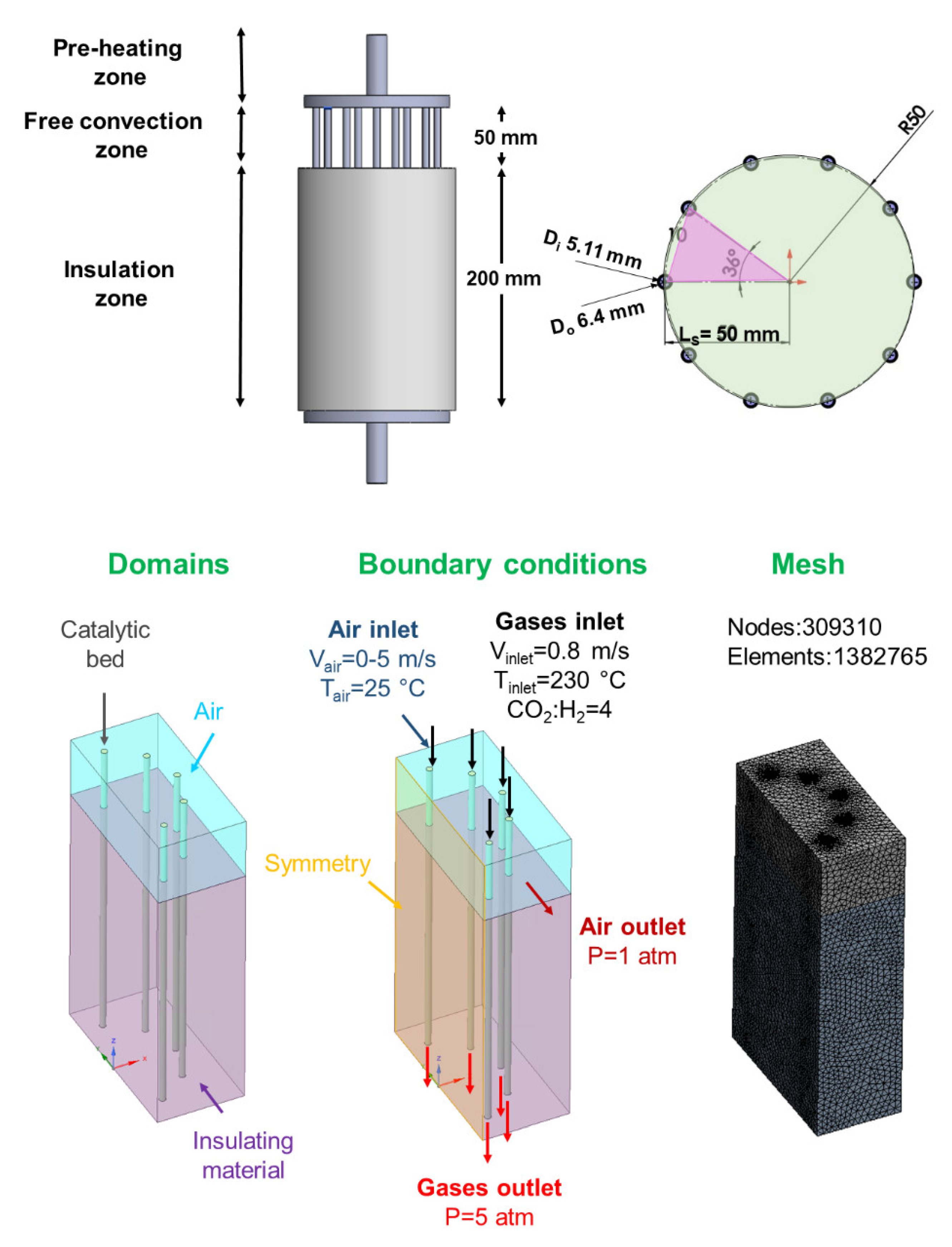
An inlet velocity was applied at the gas inlet to define the inlet velocity of the reactive mixture. This reaction condition was the same and constant for each reactive channel (Vinlet = 0.8 m/s). The inlet reactive mixture was composed of H2 = 0.20 and CO2 = 0.80, and their temperature inlet was assumed to be preheated at Tinlet = 230 °C;
(2)
An inlet velocity was applied at the air inlet to define the air velocity (Vair = 0–5 m/s), where 0 m/s refers to natural convection with no predefined air movement, and 5 m/s refers to forced air convection. The air flow was defined to circulate in only one direction, which was perpendicular to the reactive channel positions;
(3)
An outlet pressure condition was applied at the air outlet to evaluate the pressure drop along the free-convection zone. The air outlet was fixed to be open to the atmosphere;
(4)
An outlet pressure condition was applied at the gas outlet to evaluate the pressure drop along each catalytic bed. It is important to note that the catalytic bed inside each reactive channel was homogenous. This catalytic volume was mainly composed of a millimetre-sized Ni-CeO2/Al2O3-based catalyst (dp = 450 μm [38,39]) and the gases (i.e., reactants and products). The pressure of the multi-tubular reactor was fixed at 5 atm.
From this scaled-up multi-tubular reactor approach, the adaptation of the geometry design to the addition of more reactive channels (i.e., 10, 16, 19, and 23), the implementation of different reactor configurations (i.e., circular- and hexagonal-shaped distributions), the length of the separation between the reactive channels (i.e., 25, 40, and 50 mm), and the height of the free-convection zone (i.e., 25 and 50 mm) were studied. For simplification purposes, depending on the simulated reactor geometry, symmetry boundary conditions were implemented to reduce the simulation time. For multi-tubular reactor geometry with a circular-shaped reactive channel distribution, as shown in Figure 1, the reactive channel separation was fixed at 50 mm, assuming that the reactive channels were at the same distance from the main tube. The mesh of this 3D geometry model was created with a total of 139,465 nodes and 725,127 elements.
The pressure drop in the catalytic bed was calculated by approximation using the Ergun equation (Equation (2) [40].
Δ P H = 150 μ V 1 ε 2 d p 2 ε 3 + 1.75 ρ f V 2 1 ε d p 2 ε 3
where ΔP is the pressure loss through the catalytic bed; H is the height of the catalytic bed (m); μ is the gas viscosity (Pa·s); V is the velocity of the reactive mixture (m/s); dp is the particle diameter (m)—spherical equivalent; ρf is the density of the reactive mixture (kg/m3); ε represents the fractional void volume of the catalytic bed (-).
For the simulation of the temperature profiles in this scaled-up CFD model, it is important to mention that the thickness of the reacting tubes was not meshed with solid elements, but heat transfer by conduction through this thickness was considered by applying a shell conduction condition to the external walls of the tubes. Therefore, the thickness of the shell was implemented to be the same as the reactive channel (0.049 mm). After the heat of the catalytic bed was transferred by conduction through the shell, it reached the free-convection zone, and it was dissipated by air convection. In the insulation zone, the heat of the catalytic bed was also transferred by conduction into the solid insulating material.
The apparent kinetic parameters for the Sabatier reaction were obtained from previous experimentation [30]. The power law rate expressions (Equations (3) and (4)) found over a Ni-CeO2/Al2O3 catalyst were as follows:
The kinetic expression for a forward reaction:
r f = 8.38 · 10 7 · e 6.20 · 10 7 RT · ( C CO 2 ) 0.171 · ( C H 2 ) 0.683
The kinetic expression for a backward reaction:
r b = 8.78 · 10 17 · e 2.33 · 10 8 RT · ( C CO 2 ) 0.829 · ( C H 2 ) 3.316
where rf is the forward reaction (mol/m3·s); rb is the backward reaction (mol/m3·s); R is the gas constant (L⋅atm/K⋅mol); T is the temperature (K); Cco2 is the concentration of CO2 (mol/m3); CH2 is the concentration of H2 (mol/m3).
The physical properties of the catalytic bed (CB), such as the specific heat (CpCB = 6433 J/kg·K), thermal conductivity (λCB = 0.34 W/m·K), and viscosity (μCB = 1.23·10−6 kg/m·K), were obtained through the NIST database [41] and defined as constant values. The species (i.e., H2, CO2, CH4, and H2O) were modelled as ideal gases, and their mass diffusivity were calculated by the kinetic theory. Steel was selected as the material for the reactive channels, and its thermal conductivity (λS) was 16.27 W/m·K. Stone wool was used as the insulation material and its thermal conductivity (λSW) of 0.040 W/m·K was defined in the CFD model according to a description in a commercial reference [42]. A summary of the reactor dimensions, properties, and operating parameters used also for the simulations of the multi-tubular reactor with a circular-shaped distribution are presented in Table 1. In the case of the two-reactive channel and multi-tubular reactor with a hexagonal-shaped distribution, the values related to the reactor dimensions were previously adapted to carry out the simulations. In particular, hexagonal-shaped distribution was selected considering that the complexity of the model’s resolution can be reduced thanks to its geometric symmetry.
The set of partial differential equations involved in the mathematical model are specified in Table 2. A steady-state pressure-based Navier–Stokes algorithm was used to solve the equations of the CFD model. Pressure–velocity coupling with a SIMPLEC (SIMPLE-Consistent) scheme was selected as a solution method. The SIMPLEC algorithm used increased underrelaxation factors, which aided in the speed-up of the convergence.

3. Simulation Results

3.1. Multi-Tubular Fixed-Bed Reactor Geometry

On the basis of the described reactor design strategy, a series of simulations were performed to determine a suitable reactor design. In this section, two reactor geometries with a circular- and a hexagonal-shaped distribution are evaluated.

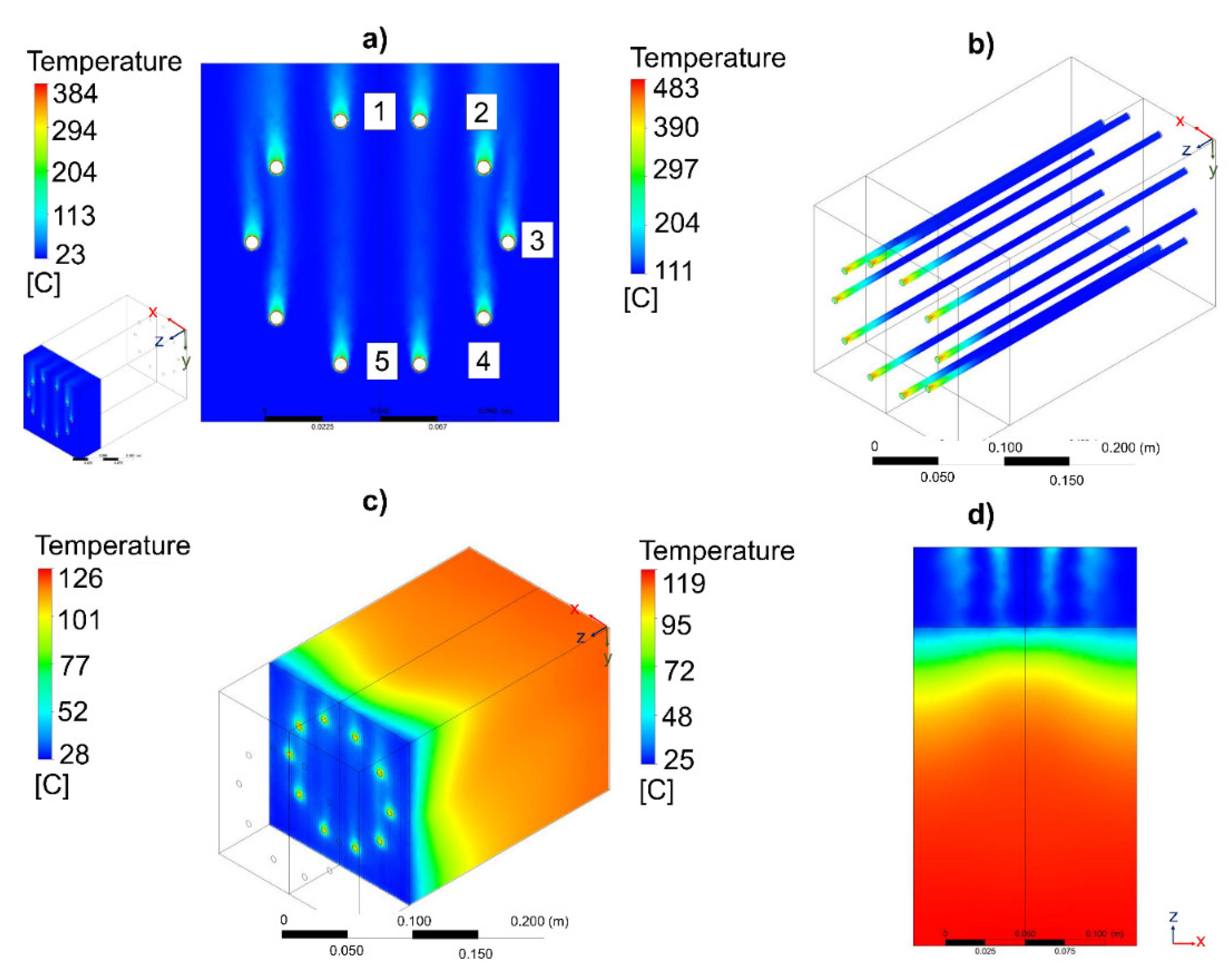
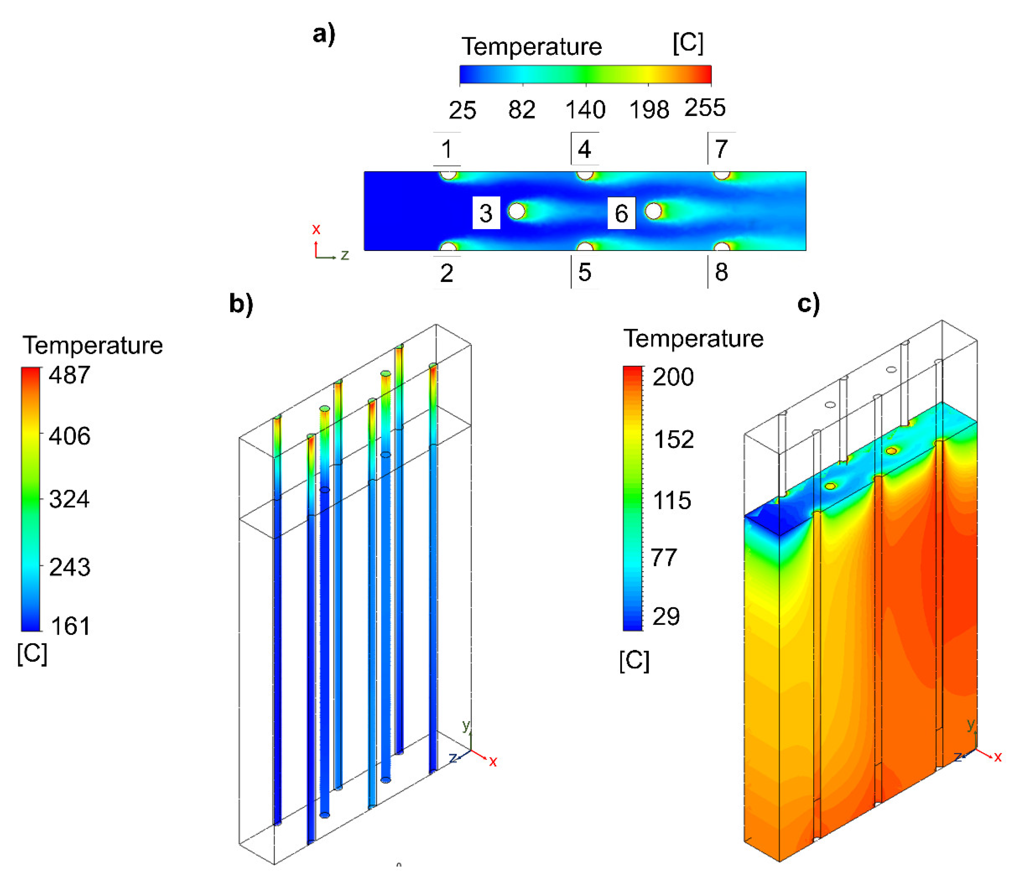
3.1.1. Circular-Shaped Distribution

At first, a multi-tubular fixed-bed reactor geometry configured with a total of 10 reactive channels under a circular-shaped distribution was evaluated considering a height of 50 mm for the free-convection zone and 200 mm for the insulation zone. The temperature behaviour of the air, the temperature of the catalytic bed, and the temperature of the insulating material were analysed at different air velocities (i.e., 0, 2, and 5 m/s). As a representative example, Figure 2 shows the influence of the inlet air velocity on the temperature profile of the multi-tubular reactor with a circular-shaped distribution. For the used air velocity of 5 m/s, the air temperature shown in Figure 2a increased from 25 to 200 °C. This increase in the air temperature was also observed in the rest of evaluated cases, being more notable under a natural convection condition, without velocity. Figure S4 suggests that this increased air temperature behaviour can be associated to the thermal interaction produced by the reactive channel configuration.
On the other hand, in the catalytic bed (see Figure S5), the temperature change along the reactor height was significative and dependent on the existence of air circulation in the first zone of the reactor. As can be observed in Figure 2b, the lowest temperature values on the catalytic bed (T = 483–111 °C) were observed at 5 m/s. This was due to the forced-convective heat transfer produced between the air and the catalytic bed. In this condition, the heat released from the catalytic bed was successfully removed by the air circulation. With the reduction of the air velocity to 2 m/s, the increases in the maximum temperatures were only inferior by 2%. In the three evaluated cases, the maximum temperatures were inferior to 500 °C, indicating that the forced-convective air heat transfer was excessive, as the temperatures along the catalytic bed were not appropriate (<230 °C) at the reactor outlet. In the case of the temperatures of the insulating material, their temperatures were also high via the implementation of a low air velocity (see Figure S6). Compared to the free-convection zone (Figure 2c), a heterogeneous temperature distribution was observed in the insulation zone of the reactor.
In the interior of the reactor (see Figure S7), the two zones can clearly be differentiated: a colder area where there was air (25–45 °C) and a hotter area where there was the insulating material (45–122 °C). The temperature was less homogeneous when there was no air circulation and when certain air temperature profiles were created in the free-convection zones. Similar behaviours were identified in the exterior of the reactor (see Figure 2d and Figure S8). The temperatures of the insulating material were much higher when a low air circulation was used (Vair = 0 m/s). With regard to the air velocity behaviour at 5 m/s (Figure S9), the values of this evaluated parameter ranged between 0 and 7.37 m/s. The minimum values were observed in the shadow area of the reactor channels. These were associated with the cylindrical shape of the reactor channels, which created local recirculation areas with low air movement.
A summary of the most relevant simulation data at the evaluated air velocity range of 0–5 m/s is presented in Table 3. According to these simulation results, it was inferred that a proper temperature profile (T = 300–480 °C) can be achieved using natural air circulation (<2 m/s), while forced air circulation excessively removes the heat of the reaction and creates low temperatures in the insulation zone (Tmax < 126 °C). Thermal interaction between the reactive channels was only identified without air circulation, causing a variation in the temperature between them (ΔT~40 °C) (see Figure S10). Furthermore, the reactor at this condition showed it had a harder time reaching maximum CO2 conversion due to the higher temperatures, which limited the chemical equilibrium. The CH4 mass fraction was the same in each of the reactive channels with forced air circulation (see Figure S11), while there were slight differences with no air circulation (see Figure S12). This last fact was due to the variation in the temperature profiles observed in each reactive channel (see Figure S13). The increase in the number of reactive channels to achieve a more homogenous thermal interaction was considered for this type of reactor design but, as a result, an asymmetric reactive channel separation was achieved (See Figure S14).

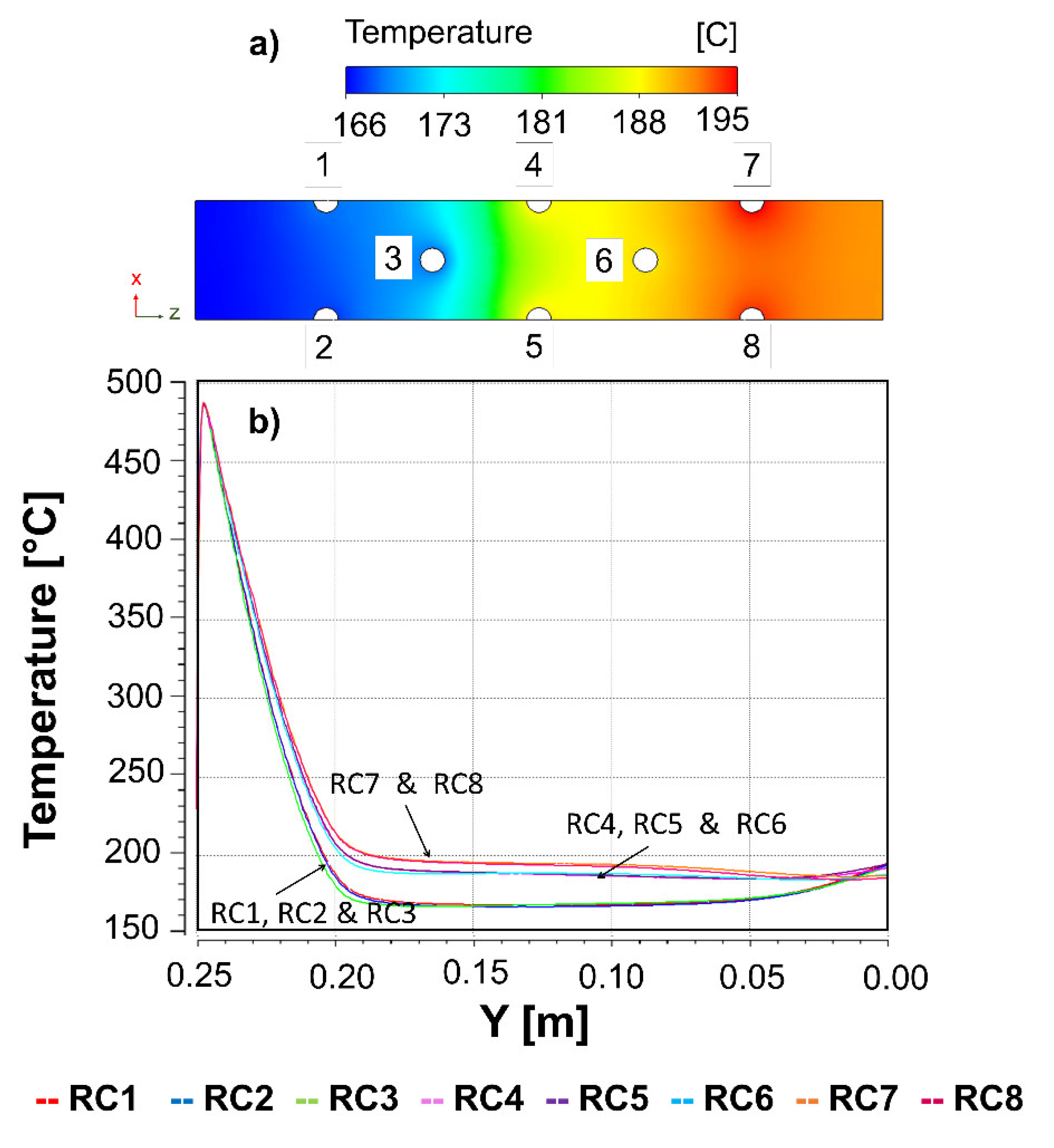
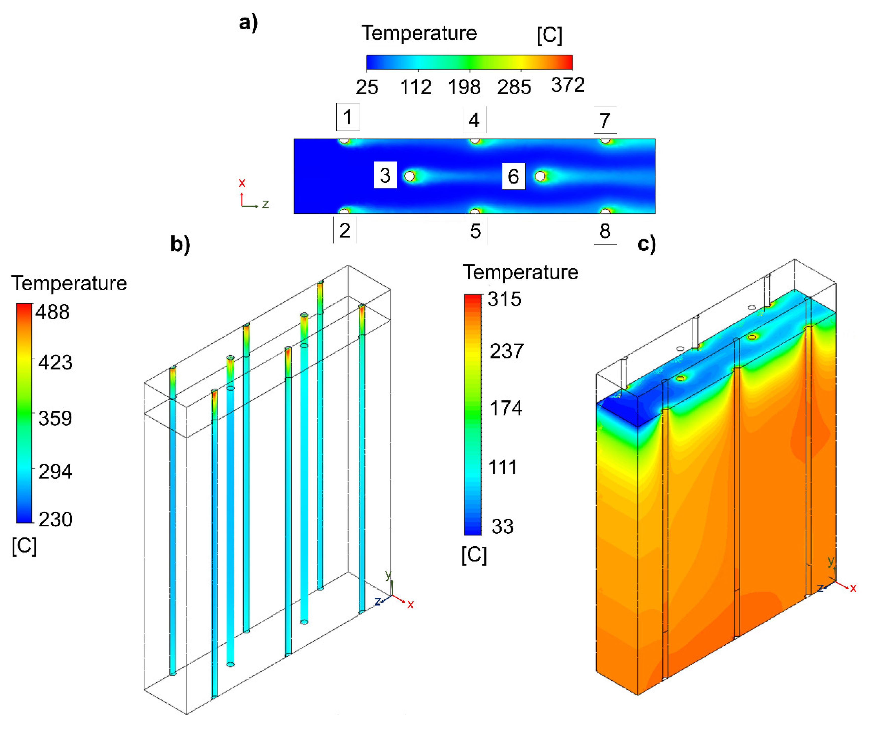
3.1.2. Hexagonal-Shaped Distribution

A multi-tubular fixed-bed reactor geometry (see Figure S2) configured with a total of 19 reactive channels under a hexagonal-shaped distribution was also evaluated. In this case, a free-convective air velocity of 1 m/s was selected considering that the difference in the maximum temperature values achieved between the two previously evaluated forced air circulations were negligible. The height of the free-convective zone and the reactive zone was kept at 50 and 200 mm, respectively. The reactive channel separation was fixed at 25 mm. Furthermore, it is important to note that the selected air velocity was representative of a reactor installed inside a container/closed space that had appropriate air circulation, with a total renewal of air every 5 min, in order to avoid the purchase of ATEX equipment (DIN1946–7 safety guidelines) throughout the reactor and, thus, significantly reducing the costs of all auxiliaries.
Figure 3 shows the temperature profiles of the different zones of the multi-tubular reactor with a hexagonal-shaped distribution. The air circulation through the noninsulated part of the reactor showed specific maximum velocities of 1.67 m/s (see Figure S15). At the selected distance separation of 50 mm, the thermal interaction between the reactive channels was controlled by the air flow direction and the reactive channel position (see Figure 3a). The reactive channels that were located in the same direction as the air and behind a channel (i.e., 4, 5, and 6) received an air flow that was slightly above 40 °C, and for the reactive channels that were located behind two reactive channels (i.e., 7 and 8), it was 60 °C. Therefore, it can be deduced that the hexagonal-shaped distribution of the reactive channels was beneficial for achieving a more homogeneous compact configuration with no significant thermal interactions. On the other hand, the temperature profiles of the reactive channels, as presented in Figure 3b, showed maximum temperatures of 487 °C, which were close to the desired range (i.e., Tmax < 500 °C). On the contrary, the temperature in the isolated zone was too low for the reaction to be effective. This temperature decreased to 162 °C, when the minimum desired values should be similar to the selected inlet temperature (Tmin > 230 °C) to avoid kinetic limitations. This fact could be solved with a higher insulation height, for example, up to 225 mm, instead of 200 mm. With this strategy, the tube would arrive hotter at the isolated zone, and then the temperature loss would be negligible, because it would be considered adiabatic. As it can be observed in Figure 3c, in the solid zone of the insulating material, the maximum temperatures were 200 °C and located in the section where the tubes achieved higher thermal interaction. However, before the insulating material, there were local variations, since it was the air circulation zone (see Figure S16). Furthermore, the wall temperature of the insulating material was identified to be different on the side where the air enters (lower) than in the area where the air leaves (higher) (see Figure S17). This was because of the higher temperature of the reactive channels in that area.
In the XZ mid-plane, at 125 mm, it was observed that the temperature profile of the insulating material had a clear distribution of approximately 29 °C between one side and the other (see Figure 4). The temperature profiles in the catalytic bed were higher in the reactive channels 4, 5, and 6, which were affected by 1, 2, and 3, and the reactive channels 7 and 8 were affected by all the others. According to these simulation results, the reactive channels can be classified into three groups: (i) a first set of reactive channels (1–3) with lower temperatures (T~170 °C); (ii) a second set of reactive channels (4–6) at medium temperatures (T~180 °C); (iii) a third set of reactive channels (7–8) at higher temperatures (T~190 °C). Consequently, it is important to emphasize that the more reactive channels added in this type of geometry, the transmission of heat in the last lines will surely be higher. The implementation of a two-way air circulation can be an alternative to avoid these thermal problems. However, it involves the implementation of auxiliary devices, undesirable for our goal. Therefore, with the view that the temperatures of the free-convective zones are key for achieving an appropriate temperature in the insulation zone and that the adjusting the reactive channel separation can be a solution to reduce the local thermal interaction, an evaluation of these geometry parameters was subsequently considered to determine the most suitable multi-tubular reactor with heat-management based on free convection.
In this hexagonal-shaped geometry (See Figure S3), the height of the free-reactive zone was reduced from 50 to 25 mm and, thus, the height of the insulation zone increased from 200 to 225 mm. Concerning the reactive channel separation, it increased from 25 to 40 mm. The air velocity was the same as the previous one (1 m/s). At these conditions, the maximum velocity was 1.55 m/s, slightly lower (−7%) than when the relative channels were at a shorter distance (see Figure S18). This fact was associated to the Venturi effect, where the velocity of a fluid increases in a system when the flow of this fluid is constant and crosses a space with a smaller area.
The influence of the reactor channel separation and reactive free-convective zone are shown in Figure 5, as well as the thermal interaction between the reactive channels. The maximum air temperatures achieved were 372 °C, located at the reacting channel/air interface. With the increase in the reactive channel separation, a significant reduction in the thermal interaction was achieved. Furthermore, a lateral thermal interaction between the reactive channels was not identified. This maximum air temperature was significantly higher than in the previous geometry (+117 °C) because of the shorter free-convection zone. On the other hand, the temperature profile of the catalytic bed, as presented in Figure 5b, showed maximum temperatures of 487 °C, which were close to the desired range (Tmax < 500 °C) and identical to the previous model. Therefore, it can be concluded that the separation between the reactive channels and the distribution of these had no influence on the maximum temperature of the catalytic beds, since the reaction heat generation capacity at these initial positions was much higher than the ability to remove it. With this strategy, the temperature of the reactive channels in the isolated zone significantly increased (+68 °C). This behaviour was due to the use of a greater height of the insulating material, causing the reactive gas mixture to arrive hotter at the insulation zone.
In the solid zone of the insulating material, as shown in Figure 5c, the maximum temperature was 315 °C (+115 °C) and displaced in the direction of the natural convection cooling air. This temperature range should be considered as the most suitable for the insulating material. In the interior (see Figure S19), the temperature of the insulation zone was 290 °C and, thus, the goal of having a temperature for the insulating material of approximately 300 °C was achieved. The temperature of the wall of the insulating material was identified to be different on the side where the air enters (lower) than in the area where the air leaves (higher) (see Figure S20).
Figure 6 suggests that the temperatures of the insulating material were better distributed between one side and the other (ΔT~20 °C). Compared to the previous hexagonal-shaped distribution, the main difference was that the temperatures in the reactive channels were much higher (between 273 and 294 °C), such that the reaction took place optimally. Regarding the temperature profiles of each reactive channel along their total axial height, the maximum temperature was identical in all of the reactive channels, below 500 °C, which is preferable due to the minimal degradation of the materials (i.e., reactive channel and catalyst). Then, the temperatures dropped rapidly and unevenly. The reactive channels with the lowest temperatures were 1 and 2, since they did not have thermal interactions with any other reactive channel. Very close was reactive channel 3 in which the thermal interaction was negligible, since it did not take place laterally. The reactive channels 4, 5, and 6 achieved a higher temperature. The maximum temperature difference was +20 °C with respect to the noninteraction. Finally, reactive channels 7 and 8 were at maximum temperatures, +30 °C compared to the conditions of reactive channels 1 and 2. Therefore, a remarkable fact of this behaviour was the nonlinear increase in the temperature differences. In the first gradient, it only increased by +20 °C and later by +10 °C. This temperature difference did not affect the simulated CH4 mass fraction composition (see Figure S21).
Therefore, from these simulation results, it was inferred that the optimal temperature profile (T = 315–488 °C) in the hexagonal reactor geometry was achieved with free-convective air circulation (1 m/s) by adjusting both the reactive channel separation (40 mm) and the height of the free-convection (0–25 mm) and insulation zones (25–275 mm). The increase in the reactive channel separation favoured positively the reduction in the lateral thermal reactive channel interactions, while the decrease in the free-convection zone and increase in the insulation zone were identified to achieve suitable temperatures at the reactor outlet. The temperature variation between the reactive channels (ΔT~20 °C) was reduced by 50% compared to the circular geometry. With respect to the possibility of increasing the number of tubes to dimension, for this geometry, in a real small-sized CO2 methanation case, it is recommended that the reactive channels are added laterally and not in the airflow direction.

3.2. Reactor Basic Unit Proposal

3.2.1. Strengths and Weakness Analysis of the Reactor Geometries

A comparison of the advantages and disadvantages between the two scaled-up multi-tubular fixed-bed reactor designs is presented in Table 4. For the case of the multi-tubular reactor geometry configured under a circular-shaped distribution, the main benefits of the scale-up of this design were exclusively related to its fabrication. The simple mechanical design of a basic unit allowed for the assembly of the reactor and maintenance of the reactive channel to be straightforward. However, a low reactive channel density and an asymmetric reactive channel separation were identified as the main drawbacks of this design. An asymmetric reactive channel separation leads to a heterogeneous thermal interaction. Furthermore, the implementation of a basic unit next to another one is limited by its circular design and, thus, placing several reactors in a parallel shape is not feasible. Compared to the circular-shaped distribution, the implementation of a hexagonal-shaped distribution was advantageous to obtain a highly compact reactor. With this reactor configuration, a high flux density was mainly achieved. Furthermore, as all the reactive channels were configured at the same distance, the use of several units is easy thanks to its simple adaptation geometry. A triangular basic unit configured under a hexagonal-shaped distribution is a practical reactor design for overcoming asymmetric reactive channel separation and the difficulty of placing several basic units next to each other. Although a more compact reactor can be designed with this reactive channel configuration, it is important to mention that the maintenance of the reactive channels and the preferential flow are the main disadvantages of this design. With this reactor geometry, the thermal interaction between the reactive channels was highly reduced. Only small thermal interactions could be achieved in the reactive channels located in the air flow direction and parallel to other reactive channels. Therefore, between the two evaluated multi-tubular fixed-bed reactor designs, the geometry designed with a hexagonal-shaped distribution is the most promising configuration to scale-up a highly compact basic unit with minimum thermal interactions between the reactive channels.

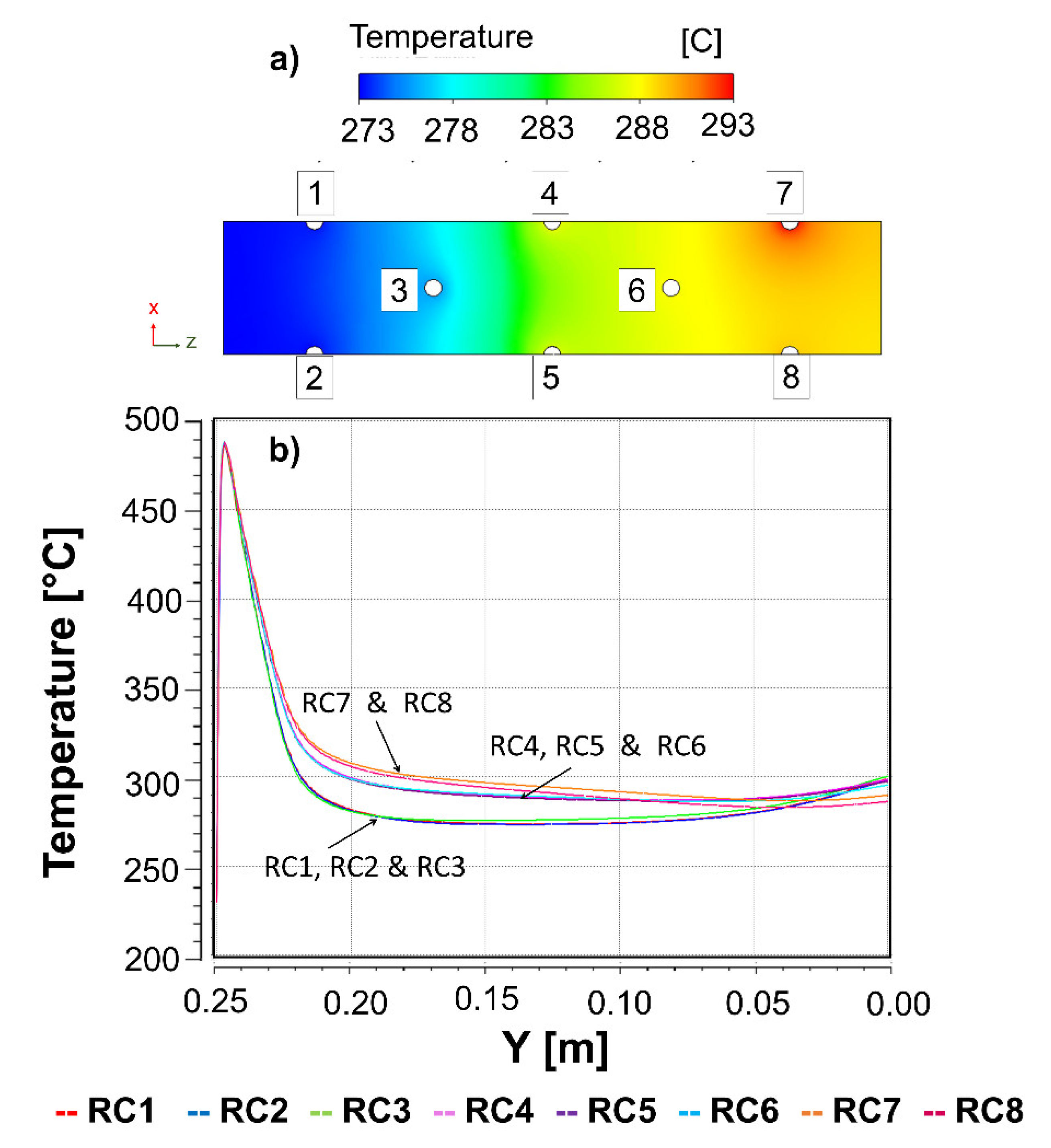
3.2.2. Sensitive Analysis

With respect to the effects of each variable on the performance of the multi-tubular fixed-bed reactor designs (See Table 5), it can be claimed that the length separation, the air velocity, and the height of the free-convection zone and insulating zone were key to achieving scaled-up free-convention heat-management for a CO2 methanation reactor. In the case of the length separation, an increase in this variable above 40 mm was found to be favourable for reducing the thermal interactions between the reactive channels. A more compact rector can be designed with the reduction of the length separation (25 mm), but a greater complexity in the assembly and maintenance of the reactive channels can be achieved. On the other hand, the implementation of a forced air velocity (5 m/s) caused an excessive loss of heat, and the flow of the air entered the insulated area too cold. The interaction between the reactive channels was practically zero. On the contrary, strong interactions between the reactive channels were identified at no forced air velocity (0 m/s). At this condition, there was a higher difficulty of thermal control due to the formation of hot spots (T ≥ 500 °C). Finally, adjusting of the height between the free-convection zone and the insulating zone was beneficial, since the desired temperature profile (230–500 °C) could be achieved. The decrease in the height of the free-convection zone (25 mm) and the increase in the height of the insulating zone (225 mm) caused a more effective temperature distribution between the reactive channels and the temperature, enough to sustain the reaction along the catalytic bed (T ≥ 230 °C).

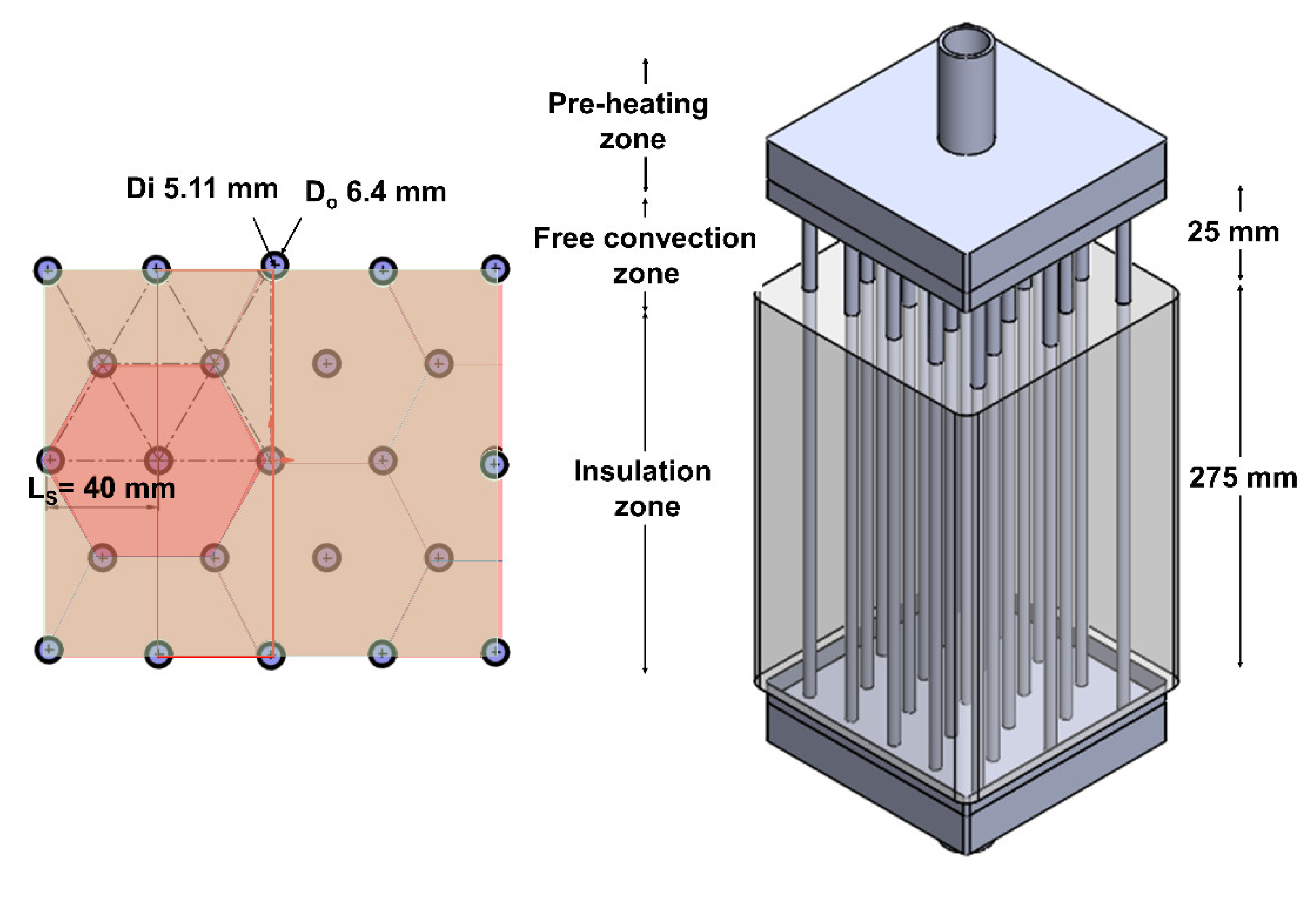
3.2.3. Prototype Design

For the proposal of a basic unit of 1 Nm3/h of SNG, the hexagonal-shaped distribution was selected as the most promising geometry design to scale-up a compact and modular multi-tubular fixed-bed reactor with a simple free-convection heat-management. With this reactive channel distribution, the scaled-up unit was adapted to a rectangular geometry composed by 23 reactive channels (See Figure 7), according to the dimensions of the catalytic bed (d = ¼″ OD and L = 250 mm). Furthermore, the separation of the reactive channel was selected to be 40 mm, since this length was identified to be optimal to achieve low thermal interactions between the reactive channels. Regarding the total height of the reactive channels, it was selected to build a 300 mm height reactor, larger than the one simulated (+20%). The additional 50 mm can act as a back-up section where the unreacted carbon dioxide can be converted or cases where the temperature profile is displaced by long-time catalyst utilisation.
In this multi-tubular fixed-bed reactor prototype, three zones were defined to guarantee its operation under free-convection heat-management. The first zone was located before the inlet reactor and was denominated as the preheating zone. Here, the reactive mixture was first preheated to 230 °C and then injected into each reactive channel at a velocity of 0.8 m/s (composed of 80% H2 and 20% CO2). The second zone was located in the first section of the reactor (0–25 mm) and was denoted as the free-convection zone. An air velocity of a 1 m/s was selected as the suitable value to control the hot spot formation (<500 °C). Finally, the last zone was denoted as the insulation zone and can be considered as the main reactor section (25–300 mm). The implementation of the insulation material was beneficial to achieve the desired temperatures at the reactor outlet (>230 °C). As a pressure of 5 atm was required to achieve the equilibrium of the reaction, it can be controlled by a valve to the outlet reactor. A summary of the dimensions and reaction conditions of the scaled-up multi-tubular fixed-bed reactor are presented in Table 6. In real PtG applications, this reactor approach can be located on the exterior to guarantee its natural air cooling or on a closed space (container) under a controlled air circulation to avoid the ATEX zone, according to safety guidelines (DIN1946–7). The weather conditions can play a decisive role on the location of this reactor device, e.g., temperature, wind, and humidity. This simulation work has shown that it is possible to operate with this design, and now onsite experimental evaluations will be key to determining its practical feasibility.

4. Conclusions

In this work, a simulation-based study assisted by a 3D CFD model was performed to propose a simple methanation reactor technology for decentralised SNG production. The multiphysical simulation proposed coupled thermal fluid dynamics and species transport modelling, and it was developed to identify a free-convective heat-management strategy for a multi-tubular reactor configuration. The developed thermal model was based on a kinetic model and on optimised reaction conditions, which were achieved by experimentation over a Ni-CeO2/Al2O3 catalyst. The reactive channel separation, the height of the free convection, and the insulation zone were the main geometry parameters to be evaluated to propose a scalable multi-tubular reactor geometry able to operate with natural convective cooling.
The simulations demonstrated that the scale-up of the multi-tubular reactor geometry was more effective under a hexagonal-shaped distribution than under a circular-shaped distribution. Furthermore, a reactor unit of 1 Nm3/h was proposed on the basis of the simulation results. A compact and modular design was achieved using a hexagonal-shape distribution. The selected multi-tubular reactor geometry was composed of 23 reactive channels (d = 1/4′, H = 300 mm), and three main zones were defined as the preheating zone, free-convection zone, and insulation zone. The optimisation of the length of the reactive channel separation (40 mm) and the height of the free-convective (0–25 mm) and insulation zone (25–300 mm) were found to be key to achieving the free-convection heat-management approach. In this proposed multi-tubular reactor unit, a decreasing temperature profile (T = 487–230 °C) for the reaction using natural convection cooling was achieved at the selected reaction conditions (Tinlet = 230 °C, P = 5 atm, and Vinlet = 0.8 m/s). The successful simulation results allow to conclude that the CFD models are a useful engineering tool to predesign scalable catalytic reactors.

Supplementary Materials

The following supporting information can be downloaded at: https://www.mdpi.com/article/10.3390/catal12091053/s1, Preliminary simulation results and Figures S1–S22.

Author Contributions

Conceptualization, T.A. and J.G.; methodology, R.B. and J.G.; software, R.B.; validation, J.G.; formal analysis, R.B., A.A. and J.G.; investigation, R.B., A.A. and J.G.; data curation, A.A.; writing—original draft preparation, A.A. and J.G.; writing—review and editing, T.A.; supervision, J.G.; funding acquisition, T.A. and J.G. All authors have read and agreed to the published version of the manuscript.

Funding

This research was funded by by the REACAT “Development of a Multichannel Catalytic Reactor” project (Acció 2020) and by the project CERES (PID2020–116093RB-C42), funded by MCIN/AEI/10.13039/501100011033.

Data Availability Statement

Data is contained within the article or Supplementary Materials.

Acknowledgments

J.G. thanks the Naturgy Energy Group; S.A. for its continued support in the technology development for renewable gas production; A.A. is thankful for the support from a Margarita Sala Grant funded by the University of Barcelona (UNI/551/2021).

Conflicts of Interest

The authors declare no conflict of interest.

References

  1. Puthalpet, J.R. Mitigation of Climate Change. In The Daunting Climate Change; CRC Press: Boca Raton, FL, USA, 2022; pp. 219–276. [Google Scholar] [CrossRef]
  2. Maroufmashat, A.; Fowler, M. Transition of Future Energy System Infrastructure; through Power-to-Gas Pathways. Energies 2017, 10, 1089. [Google Scholar] [CrossRef]
  3. Blanco, H.; Faaij, A. A Review at the Role of Storage in Energy Systems with a Focus on Power to Gas and Long-Term Storage. Renew. Sustain. Energy Rev. 2018, 81, 1049–1086. [Google Scholar] [CrossRef]
  4. Muhammed, N.S.; Haq, B.; Al Shehri, D.; Al-Ahmed, A.; Rahman, M.M.; Zaman, E. A Review on Underground Hydrogen Storage: Insight into Geological Sites, Influencing Factors and Future Outlook. Energy Rep. 2022, 8, 461–499. [Google Scholar] [CrossRef]
  5. Guilera, J.; Ramon Morante, J.; Andreu, T. Economic Viability of SNG Production from Power and CO2. Energy Convers. Manag. 2018, 162, 218–224. [Google Scholar] [CrossRef]
  6. Guilera, J.; Andreu, T.; Basset, N.; Boeltken, T.; Timm, F.; Mallol, I.; Morante, J.R. Synthetic Natural Gas Production from Biogas in a Waste Water Treatment Plant. Renew. Energy 2020, 146, 1301–1308. [Google Scholar] [CrossRef]
  7. Concas, G.; Lonis, F.; Tola, V.; Cocco, D. Power to Methane Technologies through Renewable H2 and CO2 from Biogas: The Case of Sardinia. E3S Web Conf. 2021, 312, 08015. [Google Scholar] [CrossRef]
  8. Janke, L.; Ruoss, F.; Hahn, A.; Weinrich, S.; Nordberg, Å. Modelling Synthetic Methane Production for Decarbonising Public Transport Buses: A Techno-Economic Assessment of an Integrated Power-to-Gas Concept for Urban Biogas Plants. Energy Convers. Manag. 2022, 259, 115574. [Google Scholar] [CrossRef]
  9. Gorre, J.; Ortloff, F.; van Leeuwen, C. Production Costs for Synthetic Methane in 2030 and 2050 of an Optimized Power-to-Gas Plant with Intermediate Hydrogen Storage. Appl. Energy 2019, 253, 113594. [Google Scholar] [CrossRef]
  10. Rönsch, S.; Matthischke, S.; Müller, M.; Eichler, P. Dynamische Simulation von Reaktoren Zur Festbettmethanisierung. Chem.-Ing.-Tech. 2014, 86, 1198–1204. [Google Scholar] [CrossRef]
  11. Schildhauer, T.J.; Biollaz, S.M.A. Reactors for Catalytic Methanation in the Conversion of Biomass to Synthetic Natural Gas (SNG). CHIMIA 2015, 69, 603. [Google Scholar] [CrossRef]
  12. Bremer, J.; Sundmacher, K. Operation Range Extension via Hot-Spot Control for Catalytic CO2 Methanation Reactors. React. Chem. Eng. 2019, 4, 1019–1037. [Google Scholar] [CrossRef]
  13. Jia, C.; Dai, Y.; Yang, Y.; Chew, J.W. A Fluidized-Bed Model for NiMgW-Catalyzed CO2 Methanation. Particuology 2020, 49, 55–64. [Google Scholar] [CrossRef]
  14. Hervy, M.; Maistrello, J.; Brito, L.; Rizand, M.; Basset, E.; Kara, Y.; Maheut, M. Power-to-Gas: CO2 Methanation in a Catalytic Fluidized Bed Reactor at Demonstration Scale, Experimental Results and Simulation. J. CO2 Util. 2021, 50, 101610. [Google Scholar] [CrossRef]
  15. Lefebvre, J.; Bajohr, S.; Kolb, T. Modeling of the Transient Behavior of a Slurry Bubble Column Reactor for CO2 Methanation, and Comparison with a Tube Bundle Reactor. Renew. Energy 2020, 151, 118–136. [Google Scholar] [CrossRef]
  16. Ich Ngo, S.; Lim, Y.-I.; Lee, D.; Won Seo, M.; Kim, S. Experiment and Numerical Analysis of Catalytic CO2 Methanation in Bubbling Fluidized Bed Reactor. Energy Convers. Manag. 2021, 233, 113863. [Google Scholar] [CrossRef]
  17. Engelbrecht, N.; Chiuta, S.; Everson, R.C.; Neomagus, H.W.J.P.; Bessarabov, D.G. Experimentation and CFD Modelling of a Microchannel Reactor for Carbon Dioxide Methanation. Chem. Eng. J. 2017, 313, 847–857. [Google Scholar] [CrossRef]
  18. Schollenberger, D.; Bajohr, S.; Gruber, M.; Reimert, R.; Kolb, T. Scale-Up of Innovative Honeycomb Reactors for Power-to-Gas Applications—The Project Store&Go. Chem. Ing. Tech. 2018, 90, 696–702. [Google Scholar]
  19. Engelbrecht, N.; Everson, R.C.; Bessarabov, D. Thermal Management and Methanation Performance of a Microchannel-Based Sabatier Reactor/Heat Exchanger Utilising Renewable Hydrogen. Fuel Process. Technol. 2020, 208, 106508. [Google Scholar] [CrossRef]
  20. Currie, R.; Mottaghi-tabar, S.; Zhuang, Y.; Simakov, D.S.A. Design of an Air-Cooled Sabatier Reactor for Thermocatalytic Hydrogenation of CO2: Experimental Proof-of-Concept and Model- Based Feasibility Analysis. Ind. Eng. Chem. Res. 2019, 58, 12964–12980. [Google Scholar] [CrossRef]
  21. Fuentes, I.; Gracia, F. Fluid Dynamic Analytical Model of CO2 Methanation in a Microreactor with Potential Application in Power-to-Gas Technology. Chem. Eng. Sci. 2022, 251, 117465. [Google Scholar] [CrossRef]
  22. GRTgaz Started E-Methane Production at Its Jupiter 1000 Site. Available online: https://www.grtgaz.com/en/medias/press-releases/grtgaz-started-e-methane-production-at-its-jupiter-1000-site (accessed on 1 June 2022).
  23. Bailera, M.; Lisbona, P.; Romeo, L.M.; Espatolero, S. Power to Gas Projects Review: Lab, Pilot and Demo Plants for Storing Renewable Energy and CO2. Renew. Sustain. Energy Rev. 2017, 69, 292–312. [Google Scholar] [CrossRef]
  24. Rönsch, S.; Ortwein, A.; Dietrich, S. Start-and-Stop Operation of Fixed-Bed Methanation Reactors—Results from Modeling and Simulation. Chem. Eng. Technol. 2017, 40, 2314–2321. [Google Scholar] [CrossRef]
  25. Kiewidt, L.; Thöming, J. Predicting Optimal Temperature Profiles in Single-Stage Fixed-Bed Reactors for CO2-Methanation. Chem. Eng. Sci. 2015, 132, 59–71. [Google Scholar] [CrossRef]
  26. Fache, A.; Marias, F.; Guerré, V.; Palmade, S. Optimization of Fixed-Bed Methanation Reactors: Safe and Efficient Operation under Transient and Steady-State Conditions. Chem. Eng. Sci. 2018, 192, 1124–1137. [Google Scholar] [CrossRef]
  27. Ducamp, J.; Bengaouer, A.; Baurens, P. Modelling and Experimental Validation of a CO2 Methanation Annular Cooled Fixed-Bed Reactor Exchanger. Can. J. Chem. Eng. 2017, 95, 241–252. [Google Scholar] [CrossRef]
  28. Martinez Molina, M.; Kern, C.; Jess, A. Catalytic Hydrogenation of Carbon Dioxide to Methane in Wall-Cooled Fixed-Bed Reactors. Chem. Eng. Technol. 2016, 39, 2404–2415. [Google Scholar] [CrossRef]
  29. Zhang, W.; Machida, H.; Takano, H.; Izumiya, K.; Norinaga, K. Computational Fluid Dynamics Simulation of CO2 Methanation in a Shell-and-Tube Reactor with Multi-Region Conjugate Heat Transfer. Chem. Eng. Sci. 2020, 211, 115276. [Google Scholar] [CrossRef]
  30. Alarcón, A.; Guilera, J.; Andreu, T. CO2 Conversion to Synthetic Natural Gas: Reactor Design over Ni–Ce/Al2O3 Catalyst. Chem. Eng. Res. Des. 2018, 140, 155–165. [Google Scholar] [CrossRef]
  31. Ghaib, K. 3D CFD Simulation of Reaction Cells, Cooling Cells, and Manifolds of a Flatbed Reactor for CO 2 Methanation. Chem. Eng. Technol. 2020, 43, 1994–2006. [Google Scholar] [CrossRef]
  32. Soto, V.; Ulloa, C.; Garcia, X. A 3D Transient CFD Simulation of a Multi-Tubular Reactor for Power to Gas Applications. Energies 2022, 15, 3383. [Google Scholar] [CrossRef]
  33. Pérez, S.; Del Molino, E.; Barrio, V.L. Modeling and Testing of a Milli-Structured Reactor for Carbon Dioxide Methanation. Int. J. Chem. React. Eng. 2019, 17, 20180238. [Google Scholar] [CrossRef]
  34. Moioli, E.; Gallandat, N.; Züttel, A. Model Based Determination of the Optimal Reactor Concept for Sabatier Reaction in Small-Scale Applications over Ru/Al2O3. Chem. Eng. J. 2019, 375, 121954. [Google Scholar] [CrossRef]
  35. Soto, V.; Ulloa, C.; Garcia, X. A CFD Design Approach for Industrial Size Tubular Reactors for SNG Production from Biogas (CO2 Methanation). Energies 2021, 14, 6175. [Google Scholar] [CrossRef]
  36. Alarcón, A.; Guilera, J.; Andreu, T. An Insight into the Heat-Management for the CO2 Methanation Based on Free Convection. Fuel Process. Technol. 2021, 213, 106666. [Google Scholar] [CrossRef]
  37. Swagelok Tube Data. Available online: www.swagelok.com (accessed on 1 June 2022).
  38. Alarcón, A.; Guilera, J.; Díaz, J.A.; Andreu, T. Optimization of Nickel and Ceria Catalyst Content for Synthetic Natural Gas Production through CO2 Methanation. Fuel Process. Technol. 2019, 193, 114–122. [Google Scholar] [CrossRef]
  39. Alarcón, A.; Guilera, J.; Soto, R.; Andreu, T. Higher Tolerance to Sulfur Poisoning in CO2 Methanation by the Presence of CeO2. Appl. Catal. B Environ. 2020, 263, 118346. [Google Scholar] [CrossRef]
  40. Green, D.W.; Perry, R.H. Perry’s Chemical Engineers’ Handbook; McGraw-Hill Education: Berkshire, UK, 1934; ISBN 9780071422949. [Google Scholar]
  41. NIST Chemistry WebBook. Available online: https://webbook.nist.gov/chemistry/ (accessed on 1 June 2022).
  42. Rockwool Roulrock Kraft. Available online: www.rockwool.es (accessed on 1 June 2022).
  43. Benyahia, F.; O’Neill, K.E. Enhanced Voidage Correlations for Packed Beds of Various Particle Shapes and Sizes. Part. Sci. Technol. 2005, 23, 169–177. [Google Scholar] [CrossRef]
Figure 1. Geometry, boundary conditions, and mesh of the multi-tubular fixed-bed reactor design. Specifications for the reactor design: number of reactive channels = 10; geometry configuration = circular-shaped distribution; reactive channel length separation = 50 mm; free-convection zone = 50 mm; insulation zone = 200 mm.
Catalysts 12 01053 g001
Figure 2. Influence of the air velocity on the temperature of the (a) air flow, (b) catalytic bed, (c) insulating material, and (d) exterior of the multi-tubular reactor. Specifications of the reactor design: number of reactive channels = 10; geometry configuration = circular-shaped distribution; reactive channel length separation = 25 mm; free-reactive zone = 50 mm; insulation active zone = 200 mm.
Catalysts 12 01053 g002
Figure 3. Influence of the increase in the number of reactive channels on the (a) air flow, (b) catalytic bed, and (c) insulating material. Specifications of the reactor design: number of reactive channels = 16; geometry configuration = hexagonal-shaped distribution; reactive channel length separation = 25 mm; free-reactive zone = 50 mm; insulation active zone = 200 mm.
Catalysts 12 01053 g003
Figure 4. Temperature profiles of the (a) insulating material in the XZ plane performed at the middle of the reactor (125 mm); (b) each reactive channel along its Y height (0–250 mm).
Catalysts 12 01053 g004
Figure 5. Influence of the reactive channel separation and height of the free-convective zone on the (a) air flow, (b) catalytic bed, and (c) insulating material. Specifications of the reactor design: number of reactive channels = 16; geometry configuration = hexagonal-shaped distribution; reactive channel length separation = 40 mm; free-reactive zone = 25 mm; insulation active zone = 225 mm.
Catalysts 12 01053 g005
Figure 6. Temperature profiles of the (a) insulating material in the XZ plane performed at the middle reactor (125 mm); (b) each reactive channel along its Y height (0–250).
Catalysts 12 01053 g006
Figure 7. A schematic representation of the scaled-up multi-tubular fixed-bed reactor.
Catalysts 12 01053 g007
Table 1. Dimensions, thermophysical properties, and operating parameters used in the simulation of a multi-tubular fixed-bed reactor with circular-shaped distribution for CO2 methanation reaction.
DimensionsSymbolValueUnit
Inner diameter of the reactive channelDi5.11(mm)
Outer diameter of the reactive channelDo6.4(mm)
Height of the reactive channelH250(mm)
Height of the free-convection zone HFCZ0–50(mm)
Height of the insulation zoneHIZ50–250(mm)
Length of the reactive channel separationLS50 (mm)
PropertiesSymbolValueUnit
Thermal conductivity of the reactive channelλS16.27(W/m·K)
Thermal conductivity of the insulating materialΛSW0.040(W/m·K)
Specific heat of the catalytic bed aCpCB6433(J/kg·K)
Thermal conductivity of the catalytic bed aλCB0.34(W/m·K)
Viscosity of the catalytic bed aμCB1.23 × 10−6(kg/m·K)
Particle diameter dp4.5 × 10−4(m)
Volumetric flow rate of the reactive channelQtub1.63 × 10−5(m3/s)
Area of the reactive channelS2.05 × 10−5(m2)
Viscosity of the reactive mixture aμ1.77 × 10⁻⁵(Pa·s)
Density of the reactive mixtureρf1.36(kg/m3)
Apparent density of the catalyst bρapparent,cat0.90(g/mL)
Skeletal density of the catalyst cρskeletal,cat3.50(g/mL)
Fractional void volume of the catalytic bed ε0.40 d and 0.74 e(-)
Operating ParametersSymbolValueUnit
Molar ratio of the H2/CO2-4(-)
Mole fraction of the H2H280(%)
Mole fraction of the CO2ṁco220(%)
Temperature of the reactive mixtureTinlet230(°C)
PressureP5(atm)
Velocity of the reactive mixtureVinlet0.8(m/s)
Temperature of the airTair25(°C)
Velocity of the air Vair0–5(m/s)
a Calculated using the NIST database [41]. b Experimentally estimated over a microsphere catalyst based on Ni-CeO2/Al2O3 [38]. c Experimentally estimated using a helium pycnometry technique. d Refers to the space between the microspheres and considering the wall [43]. e Calculated using helium pycnometry data.
Table 2. Governing equations of the CFD model.
Mass Balance
Conservation equation:
t ρ Y i + · ρ   v Y i = · J i + R i
Diffusion flux of the species:
J i = ρ Di I , m + u t S Ct   Y i D T , i T T
Net rate of production by the chemical reaction:
R i = M w , i r = 1 N R R ^ i , r
Energy Balance
Gas phase:
t ρ E + ·   v   ρ E + p = · k eff T i h i j i + τ ¯ e f f ·   v   + S r
E = h P ρ + y 2 2
Enthalpy for ideal gases:
h = i Y i h i
Solid phase:
t ρ h + · v p h = · k T + S s
Enthalpy for solid:
h = T ref T c p dT
Momentum Balance
Turbulence kinetic energy (k):
t ρ k + x i ρ ku j = x j μ + μ t σ k k x j + G k + G b ρ ε Y M + S k
Dissipation rate (ε):
t ρ ε + x i ρ ε u j = x j μ + μ t σ ε ε x j + C 1 ε G k + C 3 ε G b C 2 ε ρ ε 2 k + S ε
Turbulence viscosity:
μ t = C μ ρ k 2 ε
C 1 ε = 1.44 ,   C 2 ε = 1.92 and C μ = 0.09 , σ ε = 1.3 and σ k = 1.0
Table 3. A summary of the most relevant simulation data obtained for the multi-tubular fixed-bed geometry configured with a total of ten reactive channels under a circular-shaped distribution.
VTmax of the Reactive ChannelsTmin of the Reactive ChannelsThermal Interaction between Reactive Channels Tmax of the Insulating MaterialTmax of the Interior of Insulating MaterialTmax of the Exterior of Insulating Material
(m/s)(°C)(°C)(-)(°C)(°C)(°C)
0493230Yes371340313
2485140Not162153147
5483111Not126122119
Table 4. Pros and cons of the scaled-up multi-tubular fixed-bed reactor designs simulated for CO2 methanation reaction.
CircularHexagonal
Advantages
  • Simplicities in the assembly of the reactor and maintenance of the internal reactive channels.
  • All reactive channels exhibit the same mechanical resistance to flow.
  • The construction of a unit is mechanically very simple.
  • High flux density and maximum compactness.
  • All reactive channels are configured at the same distance when joining several basic units.
  • Compactness also achieved when using several basic units due to the fact of its easy adaptation geometry.
Disadvantages
  • Low reactive channel density.
  • Asymmetric reactive channel separation with this scale-up.
  • Heterogeneous thermal interaction between the reactive channels.
  • Difficulty of placing several basic units next to each other.
  • Noninsulated empty space between basic units.
  • Difficulties in the assembly of the reactor and maintenance of the internal reactive channels.
  • Preferential flux for the internal reactive channels and, thus, the implementation of a flow distributor is required.
  • Small thermal interaction in the reactive channels located in the air flow direction and parallel to other reactive channels.
Table 5. The effect of each variable on the performance of the scaled-up multi-tubular fixed-bed reactor designs simulated for the CO2 methanation reaction.
VariableEffectSelection
GeometryCircular: All reactive channels were located at the same distance from the centre; ease of construction; very complex to pack different consecutive units.
Hexagonal: The most compact geometry possible; ease of packing different units.
Hexagonal
Length separation↑ (40 mm): The increase in T decreased in the reactive channels aligned in the direction of the air. The lateral thermal interaction between the reactive channels was almost completely reduced.
(25 mm): Greater complexity in the assembly and maintenance; the device was more compact.
40 (mm)
Air velocity↑ (5 m/s): The interaction between the reactive channels was practically zero; the loss of heat was excessive; the flow of gases entered the insulated area too cold; power consumption.
(0 m/s): Strong interactions between the reactive channels; no heat removal; difficult thermal control due to the fact of hot spots; zero energy consumption.
1 (m/s)
Height of the free-convection zone and insulating zone↓ (25 mm) and(225 mm): Fully adiabatic, temperature too high throughout the reactive channels; the maximum temperature was not affected by this parameter.
(50 mm) and ↓ (200 mm): Too much heat was lost in the noninsulated area; there was not enough temperature to sustain the reaction.
50 (mm)
225 (mm)
Table 6. Dimensions and operating parameters of the scaled-up multi-tubular fixed-bed reactor.
DimensionsSymbolValueUnit
Inner diameter of reactive channelDi5.11(mm)
Outer diameter of reactive channelDo6.4(mm)
Length of the reactive channel separationLS40(mm)
Height of the reactive channelL300(mm)
Height of the free-convection zone HFCZ0–25(mm)
Height of the insulation zoneHIZ250–300(mm)
Operating parametersSymbolValueUnit
Molar ratio of the H2/CO2H2/CO24(-)
Mole fraction of the H2H280(%)
Mole fraction of the CO2ṁco220(%)
Temperature of the reactive mixture Tinlet230(°C)
PressureP5(atm)
Velocity of the reactive mixtureVinlet0.8(m/s)
Gas Hourly Space VelocityGHSV11,520(h−1)
Velocity of the airVair1(m/s)
Publisher’s Note: MDPI stays neutral with regard to jurisdictional claims in published maps and institutional affiliations.

