1. Introduction
The main energy sources are represented by fossil fuels as coal, natural gas and oil. Therefore, limited availability has prompted researchers to seek alternative and renewable energy sources, such as solar, wind, hydro, nuclear and biomass energy. In particular, biomass presents major advantages compared to sun, wind and hydro energies in terms of operations and maintenance costs. The first two, in fact, represent variable and intermittent sources of energy; the last can be generated only in a few strategic points close to water sources. Biodiesel is an energy source that has received great attention in recent decades, with very similar properties compared to conventional diesel, but with the advantages of being renewable, biodegradable, less toxic and environmentally friendly [
1].
Biodiesel is safer, contains fewer sulfur compounds and presents a higher flash point, does not produce any carbon dioxide emission, emits 80% less hydrocarbons and 50% less toxic particles, does not contain petroleum residues and can be mixed with conventional diesel. In particular, a blend containing 80% petroleum and 20% biodiesel (B20) is used in diesel engines without significant modifications [
2].
The choice of raw materials is one of the most important aspects to consider in the production of biodiesel, with a considerable contribution to the cost of production. In Europe, the most used raw material is rapeseed oil. The first-generation materials are mainly edible crops. The second generation use cooking oils, animal fats, pork lard and beef tallow. The third generation, on the other hand, are algae. In particular, microalgae play a very important role in the production of biodiesel, with numerous advantages, such as a higher oil content compared to other crops and eco-friendliness. The algae have no environmental impact, requiring a small area with a rapid growth and undeveloped lands to be cultivated without requiring the use of pesticides [
3].
On the other hand, the use of macroalgae for producing biofuels relies on the availability and huge seasonal patterns. The biomass of macroalgae differs by species, geographical region and season, and by yields and product types generated, which depend on the process technology [
4].
Biodiesel production is carried out through various processes. In direct mixing, the raw material is mixed with diesel. However, this process presents disadvantages such as a high viscosity and the acidic value of the final product, the content of free fatty acids (FFA) and the formation of rubber, making it difficult to use the final product as a fuel. The use of microemulsions involves oils mixed with an emulsifying agent, usually a short-chain alcohol. This process, however, forms carbon deposits in the engine and causes incomplete combustion. The catalytic cracking, or pyrolysis, is the catalytic transformation, in the absence of air or oxygen, of an inedible oil or animal fat into a product with combustible properties similar to diesel. Biodiesel is characterized by a mixture of methyl esters of fatty acids (FAME), obtained from lipids and alcohol through a catalyzed transesterification reaction [
4].
The reaction takes place between a triglyceride and an alcohol, in the presence of a suitable catalyst, obtaining FAMEs and glycerol. The reaction is reversible, and an excess of alcohol is necessary to shift the balance towards the production of the products. Usually, the alcohols used are methanol or ethanol thanks to their chemical and physical characteristics and lower cost. When the reaction is carried out, the speed of the reaction, the nature of the reactants, the concentration, temperature, pressure and the mechanism of the reaction are analyzed [
5].
The reaction occurs in the presence of enzymes, homogeneous or heterogeneous, alkaline or acidic catalysts, and in supercritical conditions. The process consists of three consecutive and reversible reactions, in which triglycerides are converted into diglycerides, then into monoglycerides, and finally into glycerol. An ester is produced in each of the three reactions. Thus, starting from a molecule of triglyceride at the end of the overall reaction, three molecules of esters are obtained and glycerol is produced as a byproduct (
Scheme 1) [
6].
The transesterification, or alcoholysis, is the most widely used method on an industrial scale due to its ease of execution, efficiency and low cost [
7].
In the presence of a high content of FFA in the oil, transesterification must be preceded by esterification, in which an alcohol reacts with an FFA with the formation of an ester [
8].
4. Flow Chemistry
The constant increase in the costs of the environmental impact of production processes has given considerable impetus to the search for new methodologies that reduced energy consumption and decreased both the use of hazardous substances and the production of waste, promoting a sustainable development model.
Flow chemistry, in this context, represents a valid alternative to traditional methodologies, and is strategic technology to reduce the environmental impact of chemical processes, due to more sustainable synthetic pathways. Microtechnologies enable the achievement of safer and reproducible reactions with a significant reduction of costs and by-products [
12].
Flow chemistry finds wide application in the preparation of organic and inorganic compounds, drugs, natural products and sustainable materials [
22].
In continuous flow chemistry, the reagents are introduced into a microreactor, which allowed us to optimize the reaction parameters such as mixing, flow rate and residence time. It is also possible to control the temperature and pressure conditions, the use of solvents, the stoichiometry of the reaction and the work-up operations.
The advantages of this technology are better control of experimental variables and reproducibility; easy separation of products from by-products; an increase in the reaction rate, since the reactants can undergo rapid heat and mass transfer, which positively affect productivity; better control of the heat exchange, thanks to the small size of the reactor in which the reaction takes place; and of the temperature, avoiding a dangerous and uncontrolled exothermic process.
In general, the reaction parameters such as temperature, pressure and flow rate are easier to control compared to the batch process. When deciding whether to use the batch or flow-through process, several factors need to be considered.
The most important element to evaluate is the safety of the process. The presence of hazardous materials, heat exchange and high pressures present safety risks. These risks are greatly controlled when using a continuous flow process, thanks to the small volumes of reagents used. Contact with dangerous and toxic substances is also limited, making the process safer for the operator. In addition, due to the short reaction time, it is possible to perform reactions involving reactive intermediates that could not be used in the batch process.
The optimization of temperature and reaction time is easier in the continuous flow process, varying the reactor temperature and controlling the reaction time by the flow rate. Considering the liquid–liquid reactions in batches, vigorous agitation produces emulsions, with the production of droplets which, however, are not homogeneous in size. Therefore, when a homogeneous emulsion is required, it is preferable to use a continuous flow process.
Another factor to consider when choosing the type of process to use is the reaction rate. To obtain fast batch reactions, the temperature is lowered and the reagent is then added. After a short stirring, to obtain homogeneity, the reaction mixture is heated up to the temperature at which the reaction takes place.
However, when large amounts of products are obtained, some reactions have lower yields due to poor miscibility and mass transfer.
In the flow method, on the other hand, faster mixing and a better heat transfer considerably favor the yield of the reactions. Comparing a batch and a continuous flow reactor with the same capacity, the tube has a larger surface area compared to a batch reactor.
Therefore, in the flow reactor there is a much higher surface/volume ratio. In this way, heat is transferred to and from the reaction mixture much faster. Furthermore, in the batch reactor the temperature is not homogeneous, causing an easier formation of undesired by-products.
In batch processes, the time required for the reaction is closely related to the temperature, while the continuous flow process parameters such as reactor volume and mass flow rate are crucial. Stoichiometry in the flow reactor is determined by the concentration of the reactants and the ratio between their flow rates. In the batch process, the stoichiometry is instead determined by the concentration of the chemical reagents and their volumetric ratio [
23].
In the flow process, it is possible to produce a large amount of compounds via scaling out by running up the process for a longer time, numbering up through multireactors in parallel and scaling up the process in larger reactors [
24].
The transport system for reagents and fluids converges the substances up to the mixing zone before entering the reactor, where the reaction takes place. The central zone is connected to the quenching zone, with a control of the residence time. Before the collection system, there is a pressure regulator to obtain the high pressure required. In addition, optional analysis and purification systems are integrated. All these parts are interchanged and rearranged in order to obtain a large number of possible combinations.
4.1. Types of Flow
Many important chemical transformations involve multiple phases such as gas–liquid, solid–liquid, liquid–liquid or solid–liquid-gas phases. The mixing process is very important and allows improvements in the reaction yield. In general, in a microfluidic system, the surface area/volume ratio increases as the reactor size decreases.
In a multiphase system, the interfacial area plays a very important role in phase transfer, which represents a limitation in the reaction rate. For gas–liquid mixtures, bubble, bullet or annular flows are observed in microreactors. This system is influenced by the flow rate, viscosity and properties of the channels. Gaseous reagents are usually used in stoichiometric excess due to poor interfacial mixing, slowing down the reaction.
The microfluidic system eliminates headspace and increases the surface/volume ratio of the reactor. The solid–liquid reaction is a heterogeneous reaction in which the separation process of the two phases is easier. For solid–liquid reactions, three types of bed reactors are used. The packed bed reactor has a column or channel, completely filled with a solid, thus limiting the movement of the particles. The liquid flow inside this reactor is a “plug flow”, but at high flow rates, it becomes turbulent.
In a fluidized bed reactor, the particles have a free flow and are suspended in the channel thanks to the turbulent flow of the liquid phase. The mixed reactor shows average characteristics between the two previous types. The movement of the solid at the bottom of the reactor is limited, while the upper layers are suspended and mixed thanks to the liquid phase. A solid–liquid mixture important for flow chemistry is one involving a heterogeneous catalyst [
25].
In fact, it is possible to carry out the reaction and separation in a single phase using a packed bed reactor. In liquid–liquid mixtures, the most common types of flow are laminar and projectile, and microcircuit or tubular reactors are used. In tubular reactors, laminar flow is created when parallel phases do not interrupt their respective laminar flows.
In tubular reactors, however, a projectile flow is most often observed. It forms when the perpendicular phase (phase 2) obstructs the channel, causing a build-up of pressure in phase 1. When the pressure becomes sufficiently high, a droplet detaches, and this trend is repeated several times, forming alternating bullets in each phase. The problem of the liquid–liquid mixture is associated with maintaining a steady flow which, consequently, leads to a shorter residence time.
4.2. Blending
Mixing is a process that describes how two phases interact together, highly influencing the conversion and selectivity of the reaction. The reactions carried out in flow reactors and in batches present different mixing mechanisms which, together with the kinetics of the reaction, determined whether the flow conditions are favorable. The Reynolds number (Re) is used to determine the type of flow that occurs in fluids [
26].
When the values of Re are lower than 2 × 10
3, there is a laminar flow; values higher than 3 × 10
3, on the other hand, indicate a turbulent flow. In some cases, the appearance of vortices generated by the instability of the flow occur, even at relatively low values of
Re, when a certain critical value of the Dean number (
De) exceeds
where
ρ is the density,
μ the viscosity of the fluid, 𝑢 the velocity, 𝑑
ℎ the diameter of the channel and 𝑅
𝐶 the radius of curvature. This turbulence is useful for mixing, and therefore for transport properties [
27].
4.3. Temperature
For reactions that take less than 48 h at room temperature, it is sufficient to use moderate temperatures (<80 °C) in a batch reactor to reduce the reaction time to less than an hour. If, on the other hand, the reaction that takes place at room temperature occurs in more than 172 h, higher temperatures are required to reduce the reaction time, and this, in a batch process, requires the use of a high-boiling solvent. This, however, limits the choice of solvents to be used and, therefore, complicates the course of the reaction and the purification of the product.
For reactions that require high temperatures, the use of closed containers allows the use of solvents with a lower boiling point, since the solvent can be heated above its boiling point. Both when the reactions require high and low temperatures, it is still more appropriate to use the continuous flow process due to the lower temperature gradient and the high surface/volume ratio of the reactor.
4.4. Residence Time
Residence time is the time necessary for the fluid to pass through the reactor. Residence time for biodiesel production varies according to the type of microreactor used. In general, however, an increase in residence time favors a higher yield of biodiesel. Under supercritical conditions, the residence time is reduced to a few seconds by using supercritical methanol in the absence of the catalyst. Complete conversion of triglyceride is achieved in a residence time of five minutes. However, when the transesterification under supercritical conditions is carried out in the presence of a homogeneous catalyst, the complete conversion is obtained in less than 15 s.
4.5. Structure of the Reactor
It is possible to combine several chemical reactions in sequence in one process within microreactors. A synthesis sequence in several phases takes place in several reactors arranged linearly, with the advantage that the intermediates are not isolated, but directly transferred to the reactor in subsequent flow. However, the synthesis sequence has to be divided into two or more partial sequences, and between each partial sequence the product is isolated before being carried into the next sequence [
22].
A continuous flow system is divided into eight zones: a fluid and reagent conveyor, a mixer, a reactor, a quenching unit, a pressure regulator, a collector, an analyzer and a purification system. The control of fluid movements is important because the residence time and stoichiometry of the reagents are regulated.
In most cases, control is obtained through a pumping flow technique, where a pressure difference is created between the inlet and outlet unit of the reactor. Mixing is active or passive: in the first case, the input of external energy is used to improve mixing in the reactor; in the second, the speed is proportional to the properties of the flow, pumping speed, and physical path through the respective mixing units. The reactor is the central unit in which the reactions take place.
There are three main types of reactors: a loop, a coil and a fixed-bed reactor. Accurate control of the reaction time requires an appropriate quenching procedure, otherwise most of the reactions or side reactions continue in the collecting flask, leading to undesirable results. A back pressure regulator consists of special valves which allows operation to occur at a constant system pressure. After depressurization, the reagents end up in a collecting flask [
26].
In general, in a continuous flow system, the reagents are pumped separately through a micromixer into the reactor, with a temperature control [
28].
The reactors have channels or tubes with internal diameter sizes ranging from 10 μm to a few mm. In particular, a microfluidic-type reactor (from 10 to 500 μm) and a minifluidic type (from 500 μm to a few mm). The ability to transfer heat is greatly influenced by the size of the channels. In fact, the more the diameter of the channels decreases, the more the ability to transfer heat increases [
29].
5. Reactors Used for Biodiesel Production
Conventional biodiesel production techniques required long reaction times, a high alcohol/oil molar ratio and high costs due to the recovery of excess alcohol and the catalyst used. However, several technologies developed have improved mixing and mass and heat transfer. These technologies were also supported by the use of microreactors. Several examples of transesterification carried out in flow reactors were studied and described and different kind of reactors were explored and reported in the literature [
18].
5.1. Microchannel Reactors
The microchannel reactors used to produce biodiesel usually consisted of a stainless-steel capillary or a quartz tube. The reactor was connected to an HPLC pump, and the other to a collection system, respectively. The temperature was controlled by immersing the reactor in a water bath at a controlled temperature. This type of reactor allows us to obtain rapid reaction rates, through the improvement of heat and mass transfer; a high surface/volume ratio; and a short diffusion distance [
30].
Jaree and coworkers studied the transesterification reaction of palm oil and methanol in the presence of KOH in a microtube reactor. The optimal yield of 97.14% was achieved with 1% (
w/
w) of the catalyst, with a temperature of 60 °C, a molar ratio methanol/oil of 6:1 with a residence time of 5 s. A high yield of FAME was obtained with low residence time, with a better performance obtained using a T-mixer compared to the J-mixer [
31].
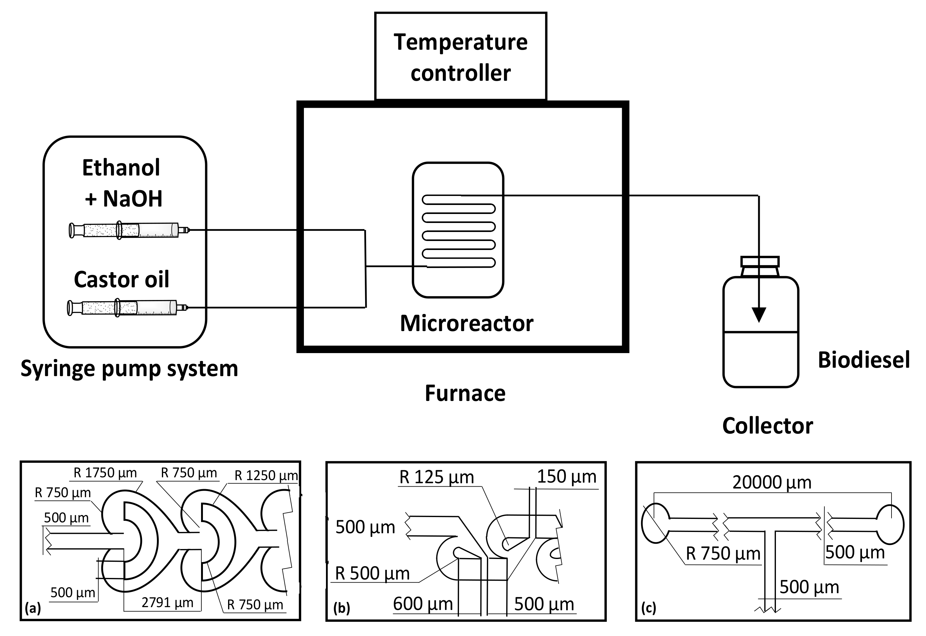
Martínez Arias and coworkers reported a continuous production of biodiesel from castor oil and ethanol with different internal geometries of the microreactors, by using Tesla-, Omega-, and T-shaped microchannels, with ethyl ester conversions of 96.7, 95.3 and 93.5%, respectively [
32].
The best performances were obtained with Tesla- and Omega-shaped microreactors, using NaOH of 1.0% (
w/
w) as catalyst at a reaction temperature of 50 °C. The transesterification reaction was studied in situ using a fiber-optic probe and monitored via near-infrared spectroscopy (
Figure 1).
The zigzag microchannel reactor presented smaller channels and more turns, which enabled smaller droplets compared to those obtained with microchannel reactors with a T or Y flow, thus allowing greater efficiency in the production of biodiesel, which is attributed to the intensification of mass transfer through passive mixing [
30].
Wen and coworkers fabricated zigzag microchannel reactors for continuous alkali-catalyzed biodiesel synthesis (
Figure 2) [
33]. The methyl ester was obtained by using NaOH as catalyst, with a yield of 99.5% and a residence time of 28 s, in the optimized conditions within the zigzag microchannel reactor.
Kalu and coworkers produced biodiesel with different degrees of conversion using homogeneous catalyst in the slit-channel reactor (
Figure 3) [
34].
Slit channel had higher active surface areas and low fabrication costs compared to microreactors. The conversion of soybean oil to biodiesel, with a molar ratio of methanol to oil of 9:1, a temperature of 56 °C and a homogeneous sodium alkoxide catalyst amount of 1.2 w/w%, increased with channel depth and required an average residence time of only 28 s for complete product conversion, with a methyl ester yield of 99.5%.
Oliveira and coworkers investigated the transesterification of soybean oil in supercritical ethanol, using carbon dioxide as co-solvent, to produce fatty acid ethyl esters (FAEE) in a continuous catalyst-free process [
35].
The reaction was performed in a microtube reactor at a temperature between 523 and 598 K, a pressure range from 10 to 20 MPa, an ethanol to oil molar ratio from 20:1 and 40:1 and with a CO2 to substrates mass ratio between 0.05:1 and 0.2:1. The addition of CO2 increased the yield of the ethyl esters and the best results were obtained at 598 K, 20 MPa, with an ethanol to oil molar ratio of 20:1 and using a co-solvent to substrate mass ratio of 0.2:1.
Da Silva and coworkers studied a continuous catalyst-free process for the transesterification of soybean oil in supercritical ethanol to produce fatty acid ethyl esters (FAEEs) [
36]. The reactions were performed in a microtube reactor at a temperature between 523 and 598 K, with a pressure range from 10 to 20 MPa, with an ethanol to oil molar ratio from 10:1 to 40:1, with the addition of carbon dioxide as a co-solvent. The yields of ethyl esters (70%
w/
w) obtained in the microtube reactor with an inner diameter 0.76 mm were higher compared to a tubular reactor with an inner diameter of 3.2 mm and were not affected by the use of CO
2 as co-solvent.
Akkarawatkhoosith and coworkers used refined palm oil, ethanol and three different co-solvents with different polarity values (THF, acetone and isopropanol) [
37].
The influence on the purity of biodiesel was evaluated under different operating conditions and was compared to the process without co-solvent. In the process, the co-solvent was mixed with palm oil to obtain a homogeneous mixture at the desired weight ratio. Subsequently, the mixture and ethanol were pumped separately into the T-way micromixer by means of two HPLC pumps. The study was conducted at a temperature between 220 and 350 °C, with a residence time of 3.5 min, an alcohol/oil molar ratio of 23:1 and a co-solvent percentage of 20% (w/w). The results indicated that the percentage of alkyl ester of fatty acids was influenced by the reaction temperature and the addition of a co-solvent could lead to an increase in the percentage, compared to a system without co-solvents, because a better homogeneity between oil and alcohol was obtained. However, the type of co-solvent became less influential when the temperature exceeded 350 °C, due to the high rate of diffusion. Alkyl ester increased sharply as the reaction time increased. The percentage exceeded 90% with the addition of any co-solvent when the residence time was 8.5 min. Therefore, a long residence time with any co-solvent was used to obtain the maximum yield. By varying the amount of co-solvent from 20 to 60% (w/w), the percentage of alkyl ester reached 83%, for each type of co-solvent used. The highest percentage, however, was obtained with acetone, which, due to its higher polarity, allowed for greater homogeneity of the mixture. By varying the molar alcohol/oil ratio from 11:1 to 38:1, the percentage of the acyl ester increased with each type of co-solvent, because the interfacial area of the oil/alcohol mixture was greater when the molar ratio increased. Therefore, in supercritical conditions, all three co-solvents used (acetone, THF, isopropanol) were important to make the mixture homogeneous, thus accelerating the reaction rate. However, when the temperature was high, and the residence time was long, the type of co-solvent used did not affect the reaction.
5.2. Packed Bed Reactor (PBR)
In the study conducted by Tran and coworkers, sunflower oil and Burkholderia lipase were used in a packed bed reactor (PBR), in which the immobilized lipase was physically trapped in the PBR column. The maximum values of triglyceride conversion and biodiesel yield were obtained with a low flow rate value of 0.1 mL/min and did not exceed 67%. This could be due to the characteristics of the lipase used and the accumulation of large amounts of glycerol. Because of its viscosity, glycerol alters the diffusion process of the product towards the lipase, preventing an increase in the biodiesel yield. However, it can be improved by arranging several PBRs in series, with the simultaneous removal of glycerol from each reactor [
38].
Buasri and coworkers reported the transesterification of waste frying oil (WFO) in packed bed reactor (PBR) with methanol, in the presence of KOH, supported on Jatropha curcas fruit shell activated carbon (KOH/JS) (
Figure 4) [
39].
In the optimized conditions, with a reaction temperature of 60 °C, a methanol to oil molar ratio of 16:1, a residence time of 2 h and catalyst bed height of 250 mm, a conversion yield of 86.7% was achieved.
Chen and coworkers investigated the continuous-flow production of fatty acid methyl esters, via the methanolysis of soybean oil, using methanol and potassium hydroxide as the catalyst, within a rotating packed bed (RPB) reactor [
40].
The optimized conditions were molar ratio of methanol to oil of 6:1, hydraulic retention time of 0.72 min, and rotational speed in the rotating packed bed (RPB) system of 900 rpm. This RPB system achieved a maximum yield of fatty acid methyl esters of 97.3% and maximum productivity of fatty acid methyl esters of 0.828 mol/min.
Silva and coworkers investigated the transesterification of Jatropha oil in a continuous catalyst-free process, using supercritical ethanol, performing the experiments in a packed-bed tubular reactor (
Figure 5) [
41].
The experiments were performed at a temperature of 573 K, a pressure of 20 MPa and keeping the mass ratio between ethanol and oil fixed at 1:1 for different residence times. The presence of free fatty acids present in vegetable oil promotes faster reaction kinetics due to simultaneous esterification and transesterification reactions. The addition of water (10%) and n-hexane as a co-solvent decreased the decomposition of fatty acids and increased the fatty acid ethyl ester yields (~90% w/w).
Baek and coworkers developed a heterogeneous catalyst characterized by a porous phenolsulfonic acid–formaldehyde resin (PAFR) applied to the esterification of carboxylic acids and alcohols, yielding 95% of esters without removing the water from the reaction mixture. In particular, the esterification in water afforded the esters in high yield and PAFR was more efficient compared to other homogeneous and heterogeneous catalysts. The recyclability of the catalyst used in the PAFR-packed flow reactor developed for the synthesis of carboxylic acids and FAME was four days (
Figure 6) [
42].
Di Serio and coworkers reported the transesterification of soybean oil with methanol in an autoclave and in a continuous packed bed reactor. The reaction was developed in the presence of a commercial Mg/Al hydrotalcite at a temperature of 220 °C, with a pressure of 55 bar and a residence time of 6 min. Calcined Mg/Al hydrotalcite was deactivated showing a decrease in the activity of 38% in 50 h but with a complete regeneration of the catalyst after washing with acetone [
43].
Halim and coworkers investigated the continuous procedure for transesterification of waste cooking palm oil in an immobilized lipase packed bed reactor (
Figure 7) [
44].
The optimum conditions for the reaction were a 10.53 cm packed bed height and a 0.57 mL/min substrate flow rate. The response surface methodology (RSM) based on a central composite rotatable design (CCRD) was adaptable for fatty acid methyl ester, and the optimum predicted yield was 80.3% compared to the actual value of 79%.
Lee and coworkers investigated a continuous process for transesterification and esterification, using immobilized Candida rugosa and Rhizopus oryzae lipases in a packed-bed reactor system (
Figure 8) [
45].
In the circulation system, the optimal reaction conditions were a reaction time of 3 h, a temperature of 45 °C, a flow rate of 0.8 mL/min and water contents of 10% with a conversion yield of biodiesel of 97.98%.
5.3. Fixed Bed Reactor (FBR)
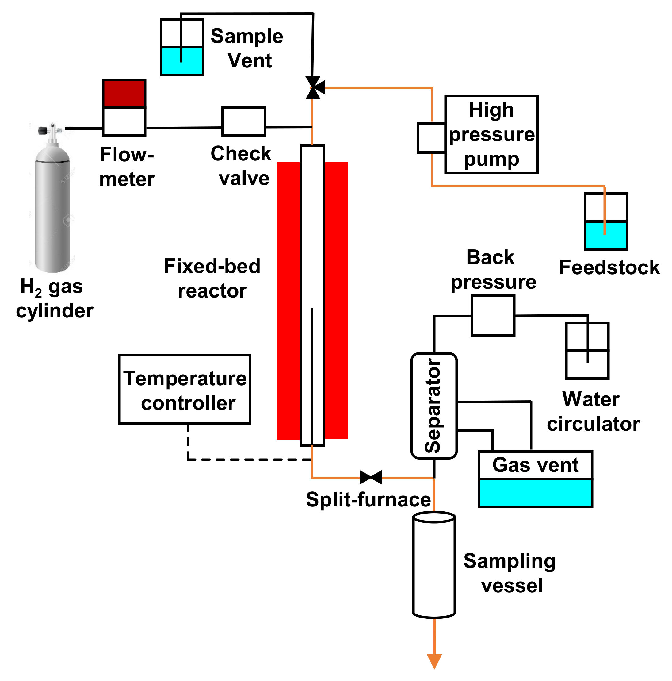
Echaroj and coworkers tested commercial and prepared Nickel–Molybdenum catalysts (NiMo) in the deoxygenation of triglyceride content of palm oil within a fixed-bed reactor at a reaction temperature between 573 and 613 K, with a pressure of 500 psi, a palm oil flow rate of 0.02 mL/min and in the presence of a H
2 flow rate of 200 mL/min. (
Figure 9) [
46].
Feng and coworkers developed a continuous esterification of free fatty acids from acidified oil with methanol in the presence of a NKC-9 cation-exchange resin in a fixed-bed reactor (
Figure 10) [
47].
In the optimized conditions after 500 h of continuous process, at 65 °C, using a methanol to oil ratio of 2.8:1, with a feed flow rate of 0.62 mL/min and a catalyst bed height of 44 cm, a conversion of 98% into biodiesel was achieved. The water content in feedstock and feed flow rate decreased the FFA conversion and the loss of sulfonic acid groups from NKC-9 resin was not observed.
Lupton and coworkers reported an efficient method for the synthesis of biodiesel using an integrated solid supported zirconium catalyst and polymer supported N-heterocycle carbene (NHC) catalyst, connected with an intermediate drying column containing ground 3 Å molecular sieves, within an integrated flow system (
Figure 11) [
48].
The reaction occurred in Omnifit glass columns fitted in a Vapourtec flow device equipped with temperature controller and pressure monitor. Vegetable oil, methanol and THF were pumped through a first catalyst bed containing ZrCl4/Ph-SBA-15, at 65 °C, with a flow rate of 11 mL/min and a residence time of 4 h. The produced water was removed in an intermediate molecular sieve 3 Å column at room temperature, and finally the reaction mixture passed through a second column containing the supported NHC catalyst at room temperature. Both catalysts were robust, affording biodiesel in high yields from a wide variety of sources.
5.4. Reactive Distillation (RD)
In reactive distillation, the chemical reaction and separation of the products took place in a single unit. This technology had several advantages, such as a shorter reaction time; did not require the use of excess alcohol; had lower production costs due to its small size; and also did not require an additional unit of separation [
30].
Thompson and coworkers studied a continuous-flow reactive distillation (RD) of canola oil for the biodiesel production (
Figure 12) [
49].
The conditions investigated were a reaction time from 3.76 to 5.56 min, a temperature from 100 °C to 130 °C, a catalyst concentration of KOH and KOCH3 from 0.13 to 0.24 mol/mol and a feed molar ratio from 3.65:1 to 4.50:1, affording product yields from 41.5% to 94.9%, productivity from 16 to 55.8 kmol/m3·h (5.6 to 19.5 m3/m3·h) and a range from 4.44 to 29.1 mol/100 mol (0.19 to 1.27% w/w) of soap formation.
In another work, a closed-loop static mixer as a continuous-flow reactor for the transesterification reactions of canola oil and methanol in biodiesel production was developed (
Figure 13) [
50].
Canola methyl esters were produced using 1.5% of sodium methoxide as catalyst, a reaction temperature of 60 °C, with a methanol/glyceride molar ratio of 4:1 and a reaction time of 30 min. This RD reactor showed shorter reaction time and higher unit productivity, a much lower excess alcohol requirement and lower capital costs due to its smaller size and the reduced need for alcohol recovery equipment, compared to batch and traditional continuous-flow processes.
He and coworkers developed and investigated a novel reactor system using reactive distillation (RD) for biodiesel preparation from canola oil and methanol, with NaOCH
3 as catalyst, at a column temperature of 65 °C and with a molar ratio between methanol and glyceride of 4:1 (
Figure 14) [
51].
The reaction time inside the pre-reactor and the RD column was 3 min, and the productivity of the RD reactor system was about 6.6 m3/h, which was from 20 to 30 times shorter and from 6 to 10 times higher compared to batch and actual continuous-flow processes.
Assabumrungrat and coworkers performed biodiesel production from soybean oil and methanol via reactive distillation processing using the commercial package Aspen Plus1 (
Figure 15) [
52].
The heterogeneous magnesium methoxide catalyst prevented neutralization, wastewater disposal and salt waste processing, thus reducing operation processes and energy consumption. The reactive distillation process catalyzed by magnesium methoxide required 153 kWh/t or 139.2 kWh/t of energy to produce biodiesel with a purity of 98% (w/w).
Agarwal and coworkers produced biodiesel from Karanja oil both in batch and continuous reactors, using a helical tube reactor and a reactive distillation (RD) column (
Figure 16) [
53].
The continuous experimental conditions were a reaction temperature of 65 °C, a reaction time of 1 h, a methanol/oil molar ratio of 5:1, 0.8% (w/w) of KOH as catalyst and a flow rate of 6.6 mL/min, with a maximum biodiesel yield of 96.6%. The residence times in the helical tube reactor and RD column were 4 and 8 min, respectively.
5.5. Microwave Assisted Process
Microwave irradiation was able to accelerate chemical reactions, providing direct energy to the reactants. Microwave heat transfer was more effective than conventional heating, and the reaction was completed in a shorter time. Conventional heating was limited due to the heterogeneous heating of the surface and depends on the thermal conductivity of the materials, specific heat and density. In a conventional heating process, the outer surface of the sample has a higher temperature, while the heat flows to the innermost parts. With the use of microwaves, however, the situation was the opposite. The most important disadvantage in this process was the low penetrating power of microwaves in absorbent materials, which was only a few centimeters [
18].
In general, the optimal microwave power values were between 300 and 700 W. A further increase could cause the evaporation of alcohol, with a negative effect on the transesterification reaction. The optimized temperature was 55–65 °C, while an increase beyond these values led to a decrease in yield due to the possible alteration of the triglyceride structure. The optimal irradiation time was from one to seven minutes when a basic homogeneous catalyst was used, with an optimal concentration of 1–1.3%
w/
w [
54].
Ding and coworkers used palm oil and an acid catalyst as raw material using microwaves (up to a power of 150 W), affording an increase in biodiesel yield [
55].
With a power of 60 W in one hour, a yield of 33% was obtained; while extending the reaction time up to eight hours, a yield of 90% was obtained. Instead, using a value of 150 W a yield of 98% was obtained in six hours. A further increase in microwave power (210 W) did not lead to any increase in yield. The methanol/oil molar ratio in the transesterification reaction is 3:1, but the reaction is reversible, so an excess of methanol is used to shift the reaction towards product formation, thereby increasing the yield. A molar ratio greater than 12:1, however, leads to a gradual decrease in yield. Therefore, to obtain the maximum yield (99%) a power of 150 W is used for microwaves, with a reaction time of six hours and an alcohol/oil molar ratio of 11:1.
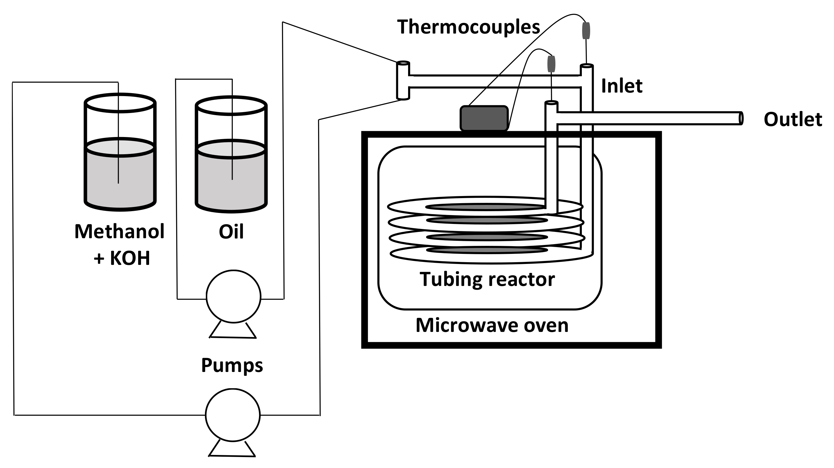
Gimbun and coworkers reported a transesterification reaction of waste cooking oil (WCO) in a continuous microwave-assisted reactor (CMAR) (
Figure 17) [
56]. The results from two-level factorial design showed that the methanol to oil molar ratio of 11.62:1, an amount of 0.68% (
w/
w) of NaOCH
3 catalyst and a reaction time of 4.47 min afforded a biodiesel conversion of 97.13%.
Leadbeater produced biodiesel using commercially available scientific microwave apparatus. The reaction was conducted under atmospheric conditions, using vegetable or waste oil, KOH 1%
w/
w as catalyst, with a molar ratio of methanol and oil of 6:1, with flow rates of 7.2 L/min, in a 4 L reaction vessel. The continuous-flow microwave methodology for the transesterification reaction resulted as more efficient compared to a conventional heated apparatus with an overall conversion of 98.9% of biodiesel [
57].
Gedanken used Con-Flow microwave synthesis to convert canola and sunflower oil to fatty-acid esters and glycerol (
Figure 18) [
58].
The Con-Flow system presented several advantages compared to batch microwave ovens, using a considerable amount of reagents, withdrawing samples of the product without stopping the process and the constant mixing of the reagents during the reaction, as a result of the flow. The product yield in the Con-Flow system was 92% for canola and 89% for sunflower oil. Otherwise, the large-scale reactions within the batch microwave, due to the limited penetration of the microwave radiation, showed reduced efficacy and the advantage of the Con-Flow method was thus emphasized.
Encinar and coworkers investigated a microwave continuous-flow system for the production of methyl esters from soybean oil (
Figure 19) [
59].
The parameters evaluated in the transesterification reaction were the temperature (50–110 °C), the methanol/oil molar ratio (3:1, 6:1, 9:1 and 12:1) and the catalyst concentration (0.5%, 1% and 1.5% (w/w) of KOH). The optimized conditions, with 2 min residence time and 200 W of power conversion, with a methanol/oil molar ratio of 12:1, a catalyst concentration of 1% (w/w) and a final temperature of 70 °C, afforded a conversion of 99% to methyl ester.
5.6. Ultrasonic Assisted Process
The function of ultrasound was to provide the mechanical energy for mixing and the activation energy necessary to start the transesterification reaction. Ultrasound was divided into two classes: high frequency (1000–10,000 kHz) with low power, and low frequency (20–1000 kHz) with high power, which was the most used class in the chemical field. Ultrasound irradiation generated cavitation, which was defined as the formation, growth and collapse of bubbles within a liquid, thus releasing a large amount of energy in a small surrounding area. Cavitation provided enough activation energy to accelerate the reaction rate. Furthermore, in reactions catalyzed by enzymes, a slight shockwave generated by the cavitation bubbles helped the propagation of the substrates towards the enzymes and contributes to the elimination of mass transfer resistance [
60].
Therefore, the collapse of the cavitation bubbles generated microturbolence and the breaking of the phase boundary. Thus, a microjet capable of determining the mixing of immiscible reagents near the interphase was generated, and this led to the formation of an emulsion. With the formation of the emulsion, both the interface and the mass transfer between the two phases increased, making the reaction faster [
61].
An ultrasonic reactor consisted of a main reaction compartment where the reagents (oil and alcohol) and the catalysts were contained and an ultrasonic transducer, connected with a controller, to generate ultrasonic waves. The reactants were transferred by specific pumps at certain flow rates to the reaction compartment in which the ultrasonic waves generated accelerated the mass transfer between the oil, alcohol and catalyst. The products were taken out of the reactor to settle in a separator, in which the biodiesel and glycerol were separated by the force of gravity. The ultrasound-assisted process accelerated the reaction, obtaining a high yield of biodiesel. This technique worked well if a homogeneous catalyst was used because it was easily homogenized in the reaction mixture using ultrasonic waves. The advantages of ultrasound-assisted transesterification were a shorter reaction time and lower energy consumption compared to the conventional mechanical stirring method, an efficient molar ratio of triglycerides and methanol and simplicity of execution [
10]. However, this technique had limitations. In some cases, the collapse of the bubble led to an accumulation of energy in the hot spots which can inactivate the enzyme. Therefore, the application of ultrasound increased the reaction temperature, unless a cooling treatment was not applied at the same time. One possible solution was to associate an ultrasound-assisted system with an agitator [
60].
Vinatoru and coworkers investigated a continuous process for the production of biodiesel from neat vegetable oil under high-power, low-frequency ultrasonic irradiation (
Figure 20) [
62]. For a residence time of 20 min, the small reactor processed 7.8 L/h, while the larger one afforded 19 L/h. Ultrasonic irradiation resulted as useful for large-scale processing of vegetable oils. The highest conversion was achieved when a small reactor and the shorter reaction time were employed.
In the study conducted by Shinde and coworkers, rapeseed oil was used as a raw material. The results of the conversion of triglycerides were analyzed by comparing the use of ultrasound and mechanical agitation. Using CH
3ONa as catalyst at 0.5% (
w/
w), at different molar ratios (6:1, 4:1, 3:1), with T = 35 °C for ultrasound and T = 65 °C for mechanical stirring, it was observed that for the method that involved the use of ultrasounds, the reaction time was shorter. The same observation was made using KOH and NaOH as catalyst. In fact, the use of ultrasound improved mass transfer, thus increasing the reaction rate [
63].
5.7. Miscellaneous
Sansawang and coworkers realized a continuous process for scale-up biodiesel production within a machine consisting of a tank of 25 L filled with used cooking oil and a tank of 6.5 L with methanol and NaOH 1%
w/
w as catalyst (
Figure 21) [
64].
The complete reaction occurred at the end of the reactor with a production rate of 1.817 L/h. A hot water system with a temperature of 40, 50 and 60 °C increased the production rate to 3.15, 3.24 and 3.37 L/h, respectively.
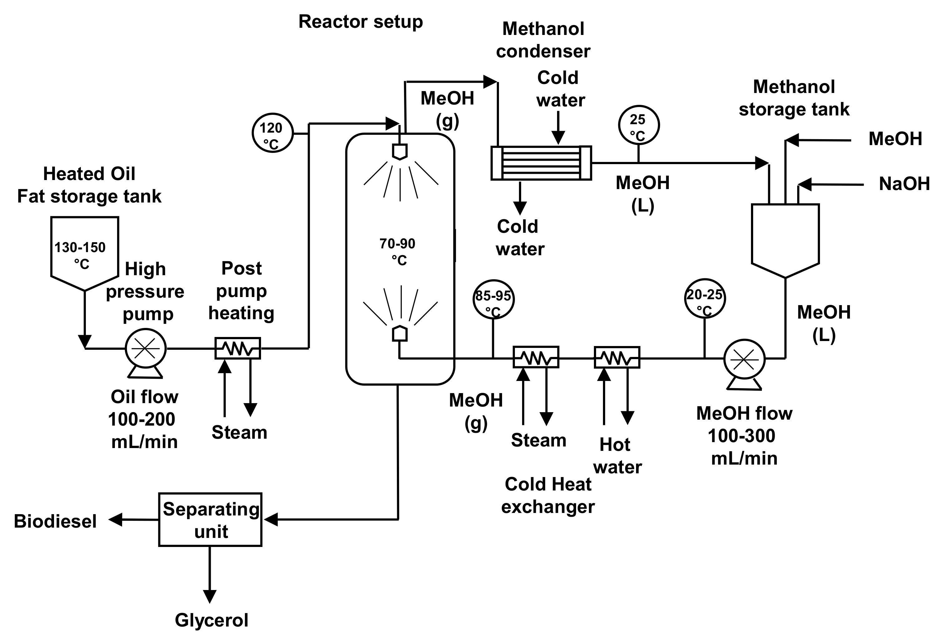
Farid and coworkers reported the production of biodiesel from fats and oils within a novel continuous gas–liquid reactor (
Figure 22) [
65].
The high reaction rate of the process facilitated work up and the separation between product and reactant. In fact, heated oil and fat were atomized and sprayed into a reaction chamber with methanol vapor; thus, the product was separated continuously while the excess of methanol streamed in the reactor. In the optimized conditions, 5–7 g of sodium methoxide/L, with a flow rate of 17.2 L/h and 10 L/h for methanol and oil, respectively, afforded a conversion of 94–96%.
Raston and coworkers reported a continuous flow conversion of sunflower oil within a film vortex fluid device (VFD) at room temperature (
Figure 23) [
66].
The optimization of the parameters prevented the use of co-solvent or complex catalysts and saponification reaction, yielding biodiesel with high purity. The recyclability of the catalyst, KOH 1M, was tested three times and the biodiesel, glycerol and catalyst were easily separated after VFD processing.
Zhu and coworkers used a tube reactor system for continuous transesterification of vegetable oil in the presence of supercritical methanol (
Figure 24) [
67].
The optimized conditions were a temperature of 310 °C, a pressure of 35 MPa, a molar ratio of 40:1 between alcohol and oil and a residence time of 25 min with a maximum production yield of 77% caused by the side reactions of unsaturated FAME at high reaction temperature. However, with gradual heating, the methyl esters yield reached more than 96%.
Ngamprasertsith and coworkers reported the continuous transesterification reaction of coconut oil and palm kernel oil, using supercritical methanol without catalyst in a tubular flow reactor (
Figure 25) [
68].
The reactions were studied at a reaction temperature of 270, 300 and 350 °C, at a pressure of 10 and 19 MPa, with methanol/oils molar ratios of from 6:1 to 42:1. The best conditions were at 350 °C, with a molar ratio of methanol/oil of 42:1 and a space time of 400 s, with a methyl ester conversion of 95 and 96% (w/w) for coconut oil and palm kernel oil, respectively.
Cheryan and coworkers used a continuous stirred-tank reactor (CSTR) system for continuous transesterification of palm oil, using pumps for continuous delivery of oil and catalyst and removal of products. The reaction was performed at 60 °C, with potassium hydroxide as catalyst, and the molar ratio between methanol and oil of 6:1. The yield of methyl esters reached 97.3% with a residence time of 60 min, while higher residence times decreased the production rate. (
Figure 26) [
69].
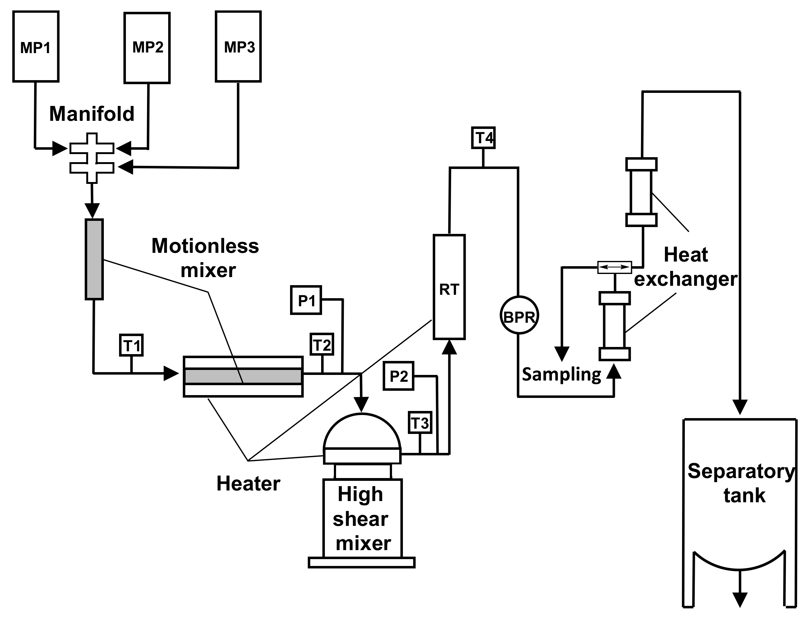
Noureddini and coworkers investigated a continuous process in a pilot plant with a motionless and a high-shear mixer for the conversion of triglycerides to methyl esters higher than 98% (
Figure 27) [
70].
An excess of alcohol favored higher conversions, and higher catalyst (NaOH in methanol) concentrations afforded higher conversions of methyl esters but increased the solubility in the glycerol layer, thus reducing the amount of FAMEs separated by gravity settling.
Noriega and coworkers investigated biodiesel production in liquid–liquid film reactors (LLFR) (
Figure 28) [
71].
In the liquid–liquid film reactor, the interfacial area is created without dispersing the oil and alcohol phases in each other, using semi-structured packaging. This type of reactor reduced separation time and increased process productivity. The optimized conditions were a constant temperature of 55 °C, with a concentration of 1% (w/w) of NaOH as catalyst and a molar ratio methanol to oil of 6:1. The packing surface area to reaction volume ratio ranged from 444 to 5333 m−1, the vegetable oil flow rate from 5 to 40 g min−1 and the reactor length from 0.25 to 1 m. The highest conversion and yield obtained were 99.9% and 97.5%, respectively, with a productivity of 2.5 m3 biodiesel m−3 h−1.
Komers and coworkers reported a cascade of four flow-stirred reactors at a steady state of 60 °C for the continuous methanolysis of rapeseed oil catalyzed by KOH [
72].
The optimal combination of initial conditions and the number and volumes of reactors in the cascade afforded a rapeseed oil conversion of 98.5%.
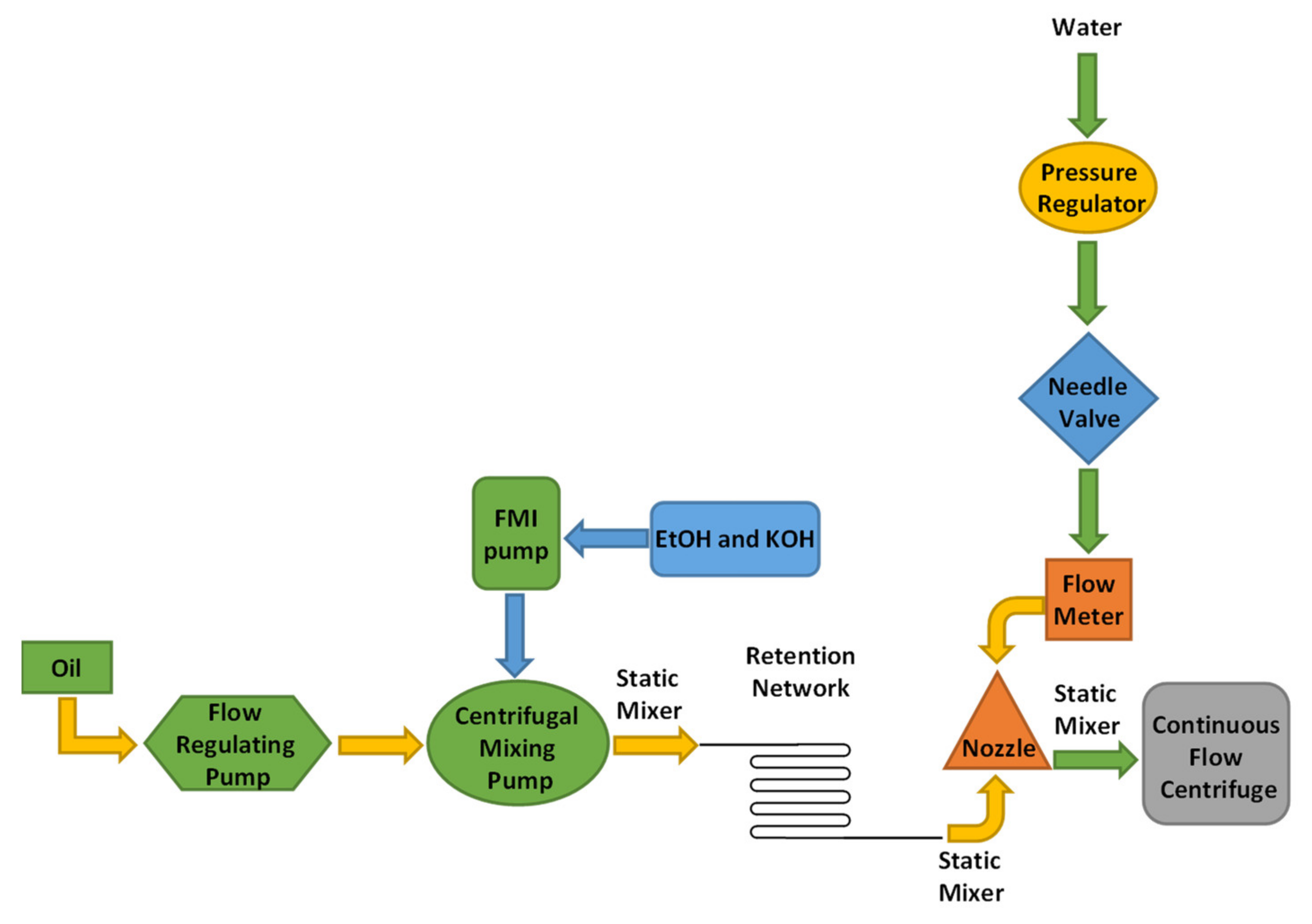
Peterson and coworkers investigated continuous flow esterification to produce biodiesel from rapeseed oil and ethanol (
Figure 29) [
73].
This system consisted of an empty spinning centrifuge placed in a reactor. The two liquid phases, which were immiscible, were pumped into the annular zone between the reactor and the centrifuge, where mixing took place. The mixture was then transferred to the centrifuge, where the two phases were separated by centrifugal forces [
74].
The oil feed rate was 0.38 L/min and produced 945 L (250 gal) per batch.
Suranani and coworkers reported a continuous synthesis of biodiesel from fresh oil (FO) and used cooking oil (CO) using a corning
® Advanced FlowTM Reactor (AFR) similar to a plug flow reactor (PFR) (
Figure 30) [
75].
The reaction was performed in the presence of sulfuric acid 2% (w/w), with a temperature of 80 °C and a feed flow rate of 30 mL/h, achieving a maximum oil conversion of 99 and 93% in AFRTM for FO and CO, respectively.
Nabetani and coworkers developed a non-catalytic transesterification of triglycerides in a continuous-flow bubble column reactor (
Figure 31) [
76].
The bubble column reactor was similar to reactive distillation, where oil was retained in the liquid phase while the reaction products in the gas phase were continuously removed from the reactive zone. The reaction was developed in a continuous-flow bubble column reactor containing palm oil, with a liquid volume of 200 mL, in the presence of methanol with feed flow rates of 1.5, 3.0, and 6.0 mL/min, and with reaction temperatures of 250, 270, and 290 °C. The biodiesel productivity increased with the reaction temperature and methanol feed flow rate, while the purity of the methyl ester decreased.
To sum up the characteristics of the continuous flow technology, advantages and drawbacks of the described reactors are reported in
Table 1.


