Article

Synthesis and Photoelectrocatalytic Applications of TiO2/ZnO/Diatomite Composites

1
College of Chemistry, Beijing University of Chemical Technology, Beijing 100029, China
2
Analysis and Test Center, Beijing University of Chemical Technology, Beijing 100029, China
*
Author to whom correspondence should be addressed.
Catalysts 2022, 12(3), 268; https://doi.org/10.3390/catal12030268
Submission received: 31 December 2021 / Revised: 27 January 2022 / Accepted: 8 February 2022 / Published: 28 February 2022
(This article belongs to the Special Issue 10th Anniversary of Catalysts—Feature Papers in Photocatalysis)

Abstract

:
ZnO and TiO2 are semiconductor nanomaterials that are widely used in photocatalysis. However, the relatively high recombination rate and low quantum yield of photogenerated electron–hole pairs limit their practical applications. In this study, a series of TiO2/ZnO/diatomite composites with various compositions were successfully prepared via a two-step precipitation method. They exhibited stronger UV–visible absorption properties and substantially lower fluorescence intensities than those of ZnO and ZnO/diatomite, which was mainly due to the low recombination rate of the photogenerated electron–hole pairs in the composite system. The reaction intermediates of methylene blue were detected by liquid chromatography–mass spectrometry, and the degradation process was determined. The best composite catalyst was used for the degradation of gaseous methylbenzene and gaseous acetone. The gaseous acetone degradation product was determined to be acetaldehyde via gas chromatography–mass spectrometry. The results show that the composite catalyst exhibited a good photocatalytic degradation of both liquid pollutants and harmful volatile gases. When applied to the hydrogen and oxygen evolution reactions, the composite catalyst retained a good photoresponsivity and electrolytic efficiency.

1. Introduction

Catalysts are widely used in modern chemical, energy, petroleum, and environmental industries [1]. As a key national technology, catalytic technology plays an important role in the national economy, environment, and public health [2,3]. Photocatalytic reactions are chemical reactions of substances under light in the presence of photocatalysts. Owing to their advantages of room-temperature reaction and the direct utilization of solar energy, they have attracted considerable attention for air and water pollution treatment [4,5]. The effective inhibition of the recombination of photogenerated electron–hole pairs and the improvement of photocatalytic activity have become active areas of research [6,7]. Research shows that the photocatalytic efficiency can be effectively improved by improving the adsorption performance of the target degradation materials and reducing the recombination rate of photogenerated electron–hole pairs in photocatalysts. ZnO and TiO2 are common semiconductor nanomaterials with an appropriate theoretical bandwidth (approximately 3.2 eV) and high thermal and chemical stabilities [8,9]. They are commonly used to degrade organic pollutants and demonstrate good application prospects in the field of catalysis [10,11,12]. However, the fast recombination rate of electron–hole pairs in these photocatalysts restricts their application in photocatalytic technologies [13,14,15]. Generally, ZnO and TiO2 form composites with substrate materials with large specific surface areas. The recombination rate of photogenerated carriers can be inhibited by controlling the size of the nanoparticles and by combining the electron or hole capture centers introduced by the substrate to increase the exposure time of catalytic active sites, which has become an effective method of improving the photocatalytic efficiency of ZnO and TiO2 [16,17].
As a type of siliceous rock, diatomite is mainly composed of SiO2. It has a rich pore structure, and its surface contains a large number of hydroxyl groups [18,19,20]. It has stable chemical properties, good electron and hole transmission abilities. As a base material, diatomite can bond with hydroxyl groups on the surface of ZnO or TiO2. While diatomite and ZnO or TiO2 composites have been reported [21,22], there are few reports on the regulation of the crystal structure of TiO2/ZnO/diatomite composites and its relationship with catalytic properties. The mechanism for improving the photocatalytic properties of these composites requires further exploration. In this study, TiO2(X%)/ZnO(10%)/diatomite composite catalysts were prepared by a two-step precipitation method, and the adsorption/photocatalytic efficiency of the composite catalyst containing 30% TiO2 for methylene blue (MB) was close to 80.34% after 150 min under visible light. The catalytic efficiencies of the best catalyst were 63.5% and 53.3% after 210 min of adsorption and photodegradation for gaseous methylbenzene and gaseous acetone, respectively. In addition, the degradation mechanisms and products were characterized.

2. Results and Discussion
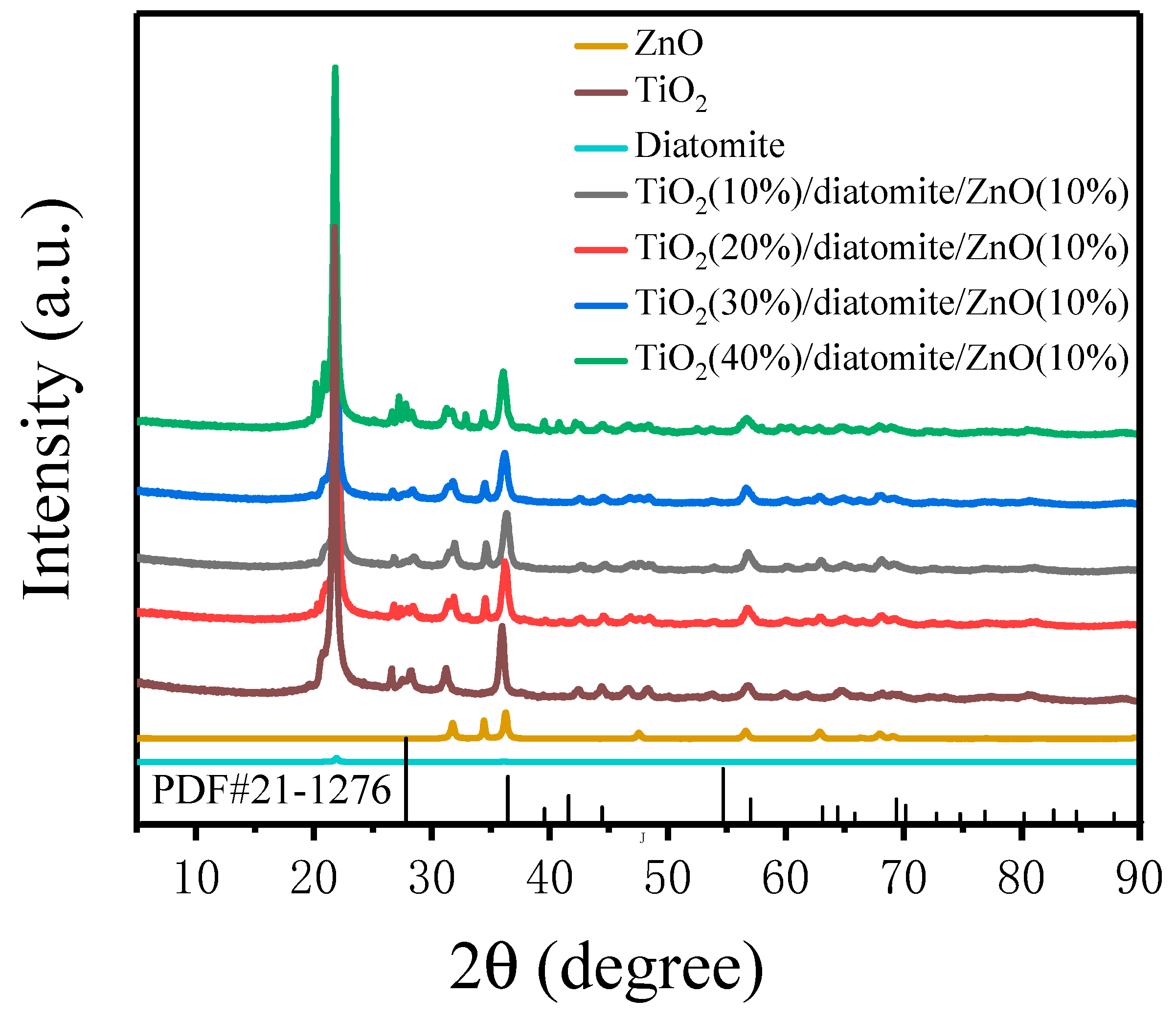
2.1. Phase Analysis

Figure 1 shows the X-ray diffraction (XRD) figures of the composite catalysts. The diffraction peaks at 21.8° and 36.5° belong to diatomite [23,24], and the diffraction peaks at 25.27°, 37.82°, 47.8°, and 54.3° belong to the (101), (004), (200), and (211) planes of rutile TiO2(PDF#21-1276), respectively [25]. The diffraction peaks at 31.8°, 34.4°, 36.2°, 47.5°, 56.6°, 62.8°, and 67.9° belong to the (100), (002), (101), (102), (110), (103), and (112) planes of hexagonal wurtzite ZnO, respectively. The characteristic diffraction peaks present in the TiO2(X%)/ZnO(10%)/diatomite composite catalysts demonstrated the successful preparation of the composite.

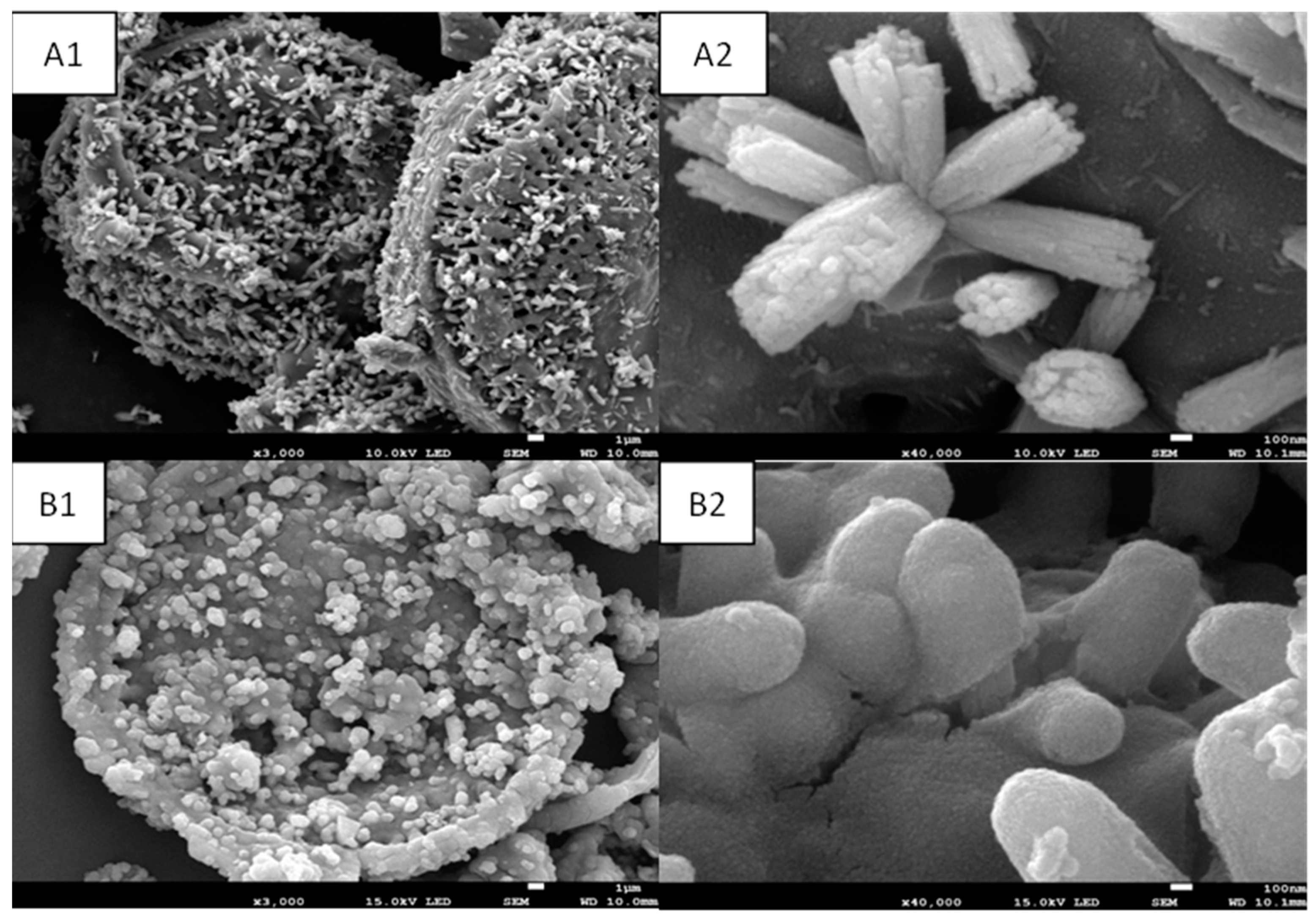
2.2. Morphological Analysis

The scanning electron microscopy (SEM) analysis of the different catalysts is shown in Figure 2, revealing that the surface of diatomite contained numerous pore. Figure 2A1,A2 shows that the ZnO nanoparticles were regularly distributed on the surface of diatomite with a diameter of approximately 30 nm. The infrared spectrum shows that there was a large number of hydroxyl groups on the surface of diatomite and zinc oxide. The ZnO surface was rich in hydroxyl groups, which easily reacted with the hydroxyl groups on the diatomite surface. Figure 2B1,B2 shows that the TiO2 nanoparticles were evenly distributed on the surfaces of diatomite and ZnO, with a diameter of approximately 5 nm. The particles were small and easily loaded on the diatomite and ZnO surfaces.

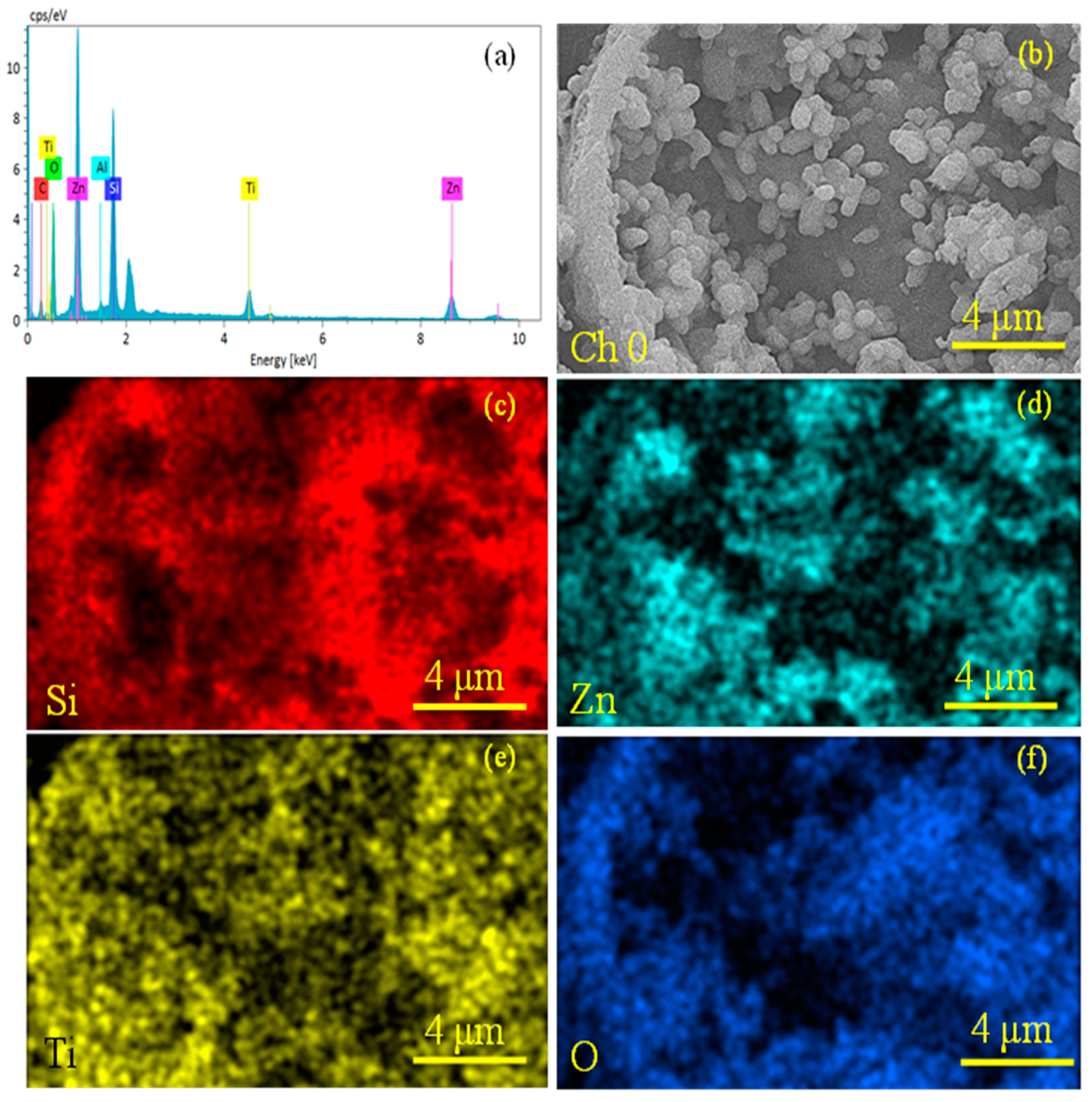
2.3. Elemental Analysis
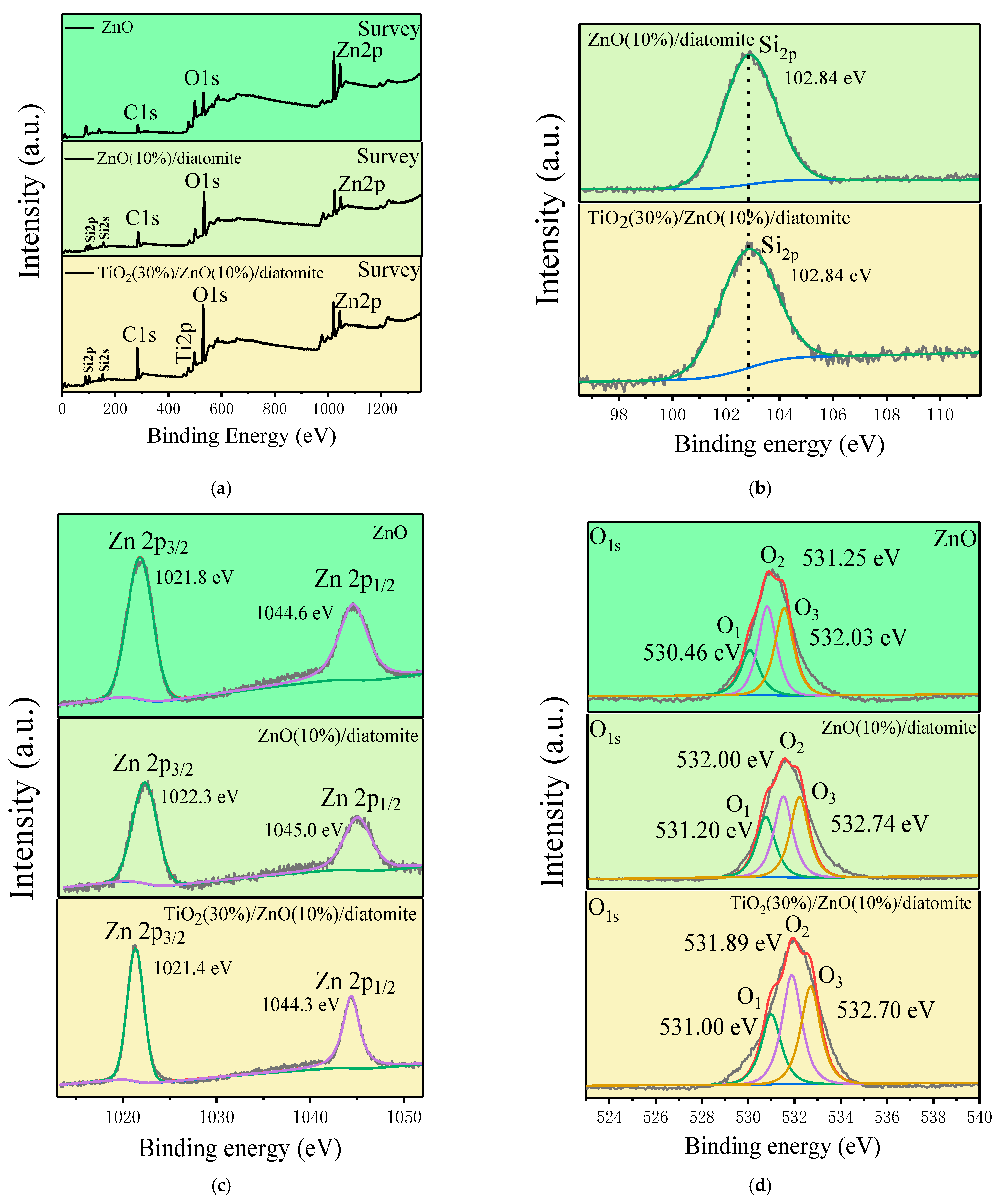
The energy-dispersive spectroscopy (EDS) analysis of the TiO2(30%)/ZnO(10%)/diatomite sample is shown in Figure 3. The elemental survey of TiO2(30%)/ZnO(10%)/diatomite is shown in Figure 3a, and Figure 3b shows the corresponding SEM image. Figure 3c–f shows the elemental maps of Si, Zn, Ti, and O, respectively, in TiO2(30%)/ZnO(10%)/diatomite, and no other impurity elements could be observed. These results confirmed the phase purity of the product.

2.4. XPS Analysis

Figure 4 shows the X-ray photoelectron spectroscopy (XPS) energy profiles of the different catalysts. In Figure 4a, O, C, Ti and Zn were detected on the different composite catalysts surfaces. Figure 4b shows the Si for ZnO and ZnO(10%)/diatomite. There was no obvious difference between the two. Figure 4c shows the Zn for ZnO, ZnO(10%)/diatomite and TiO2(30%)/ZnO(10%)/diatomite. There was no obvious difference between the three. In the O spectra in Figure 4d, three types of oxygen species were present: surface oxygen (O1), metallic oxygen (O2), and oxygen vacancies (O3). The proportions of the three types of oxygen species varied between the different catalysts, among which the difference in oxygen vacancies was the most noticeable. As is shown in Table 1, the proportion of oxygen vacancies in the TiO2(30%)/ZnO(10%)/diatomite composite catalyst was the largest, and a larger quantity of oxygen vacancies generally improved the adsorption performance of the catalyst and the photocatalytic activity of the material.

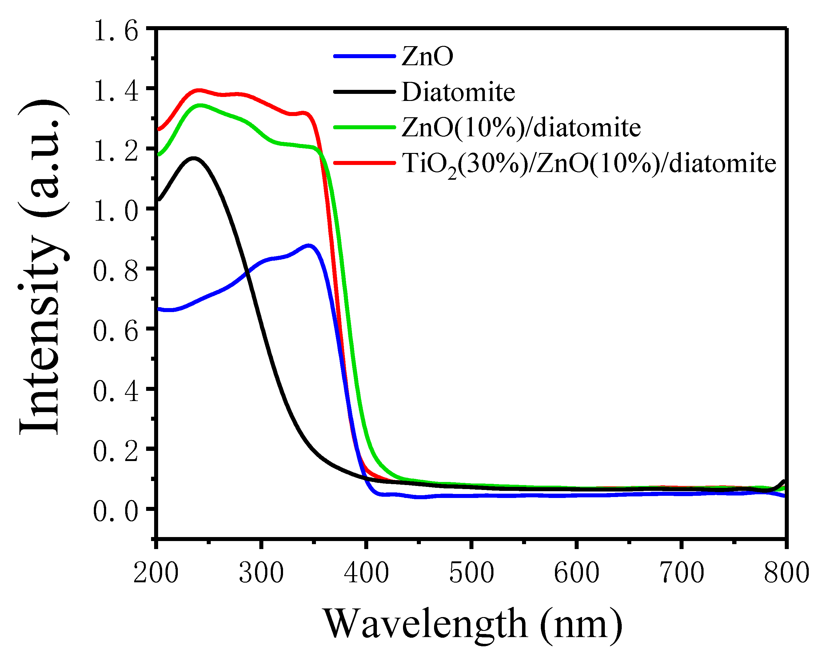
2.5. UV–Vis Diffuse Reflectance Spectra

Ultraviolet–visible (UV–vis) spectra can be used to reveal the light absorption capacity of a catalyst [26]. As shown in Figure 5, the TiO2(30%)/ZnO(10%)/diatomite composite catalyst could absorb more visible light than diatomite, ZnO, and ZnO(10%)/diatomite, and the absorption edge was located at 400 nm. The composite catalyst had a wider visible light absorption range and higher absorption intensity, which generally improved the photocatalytic performance.

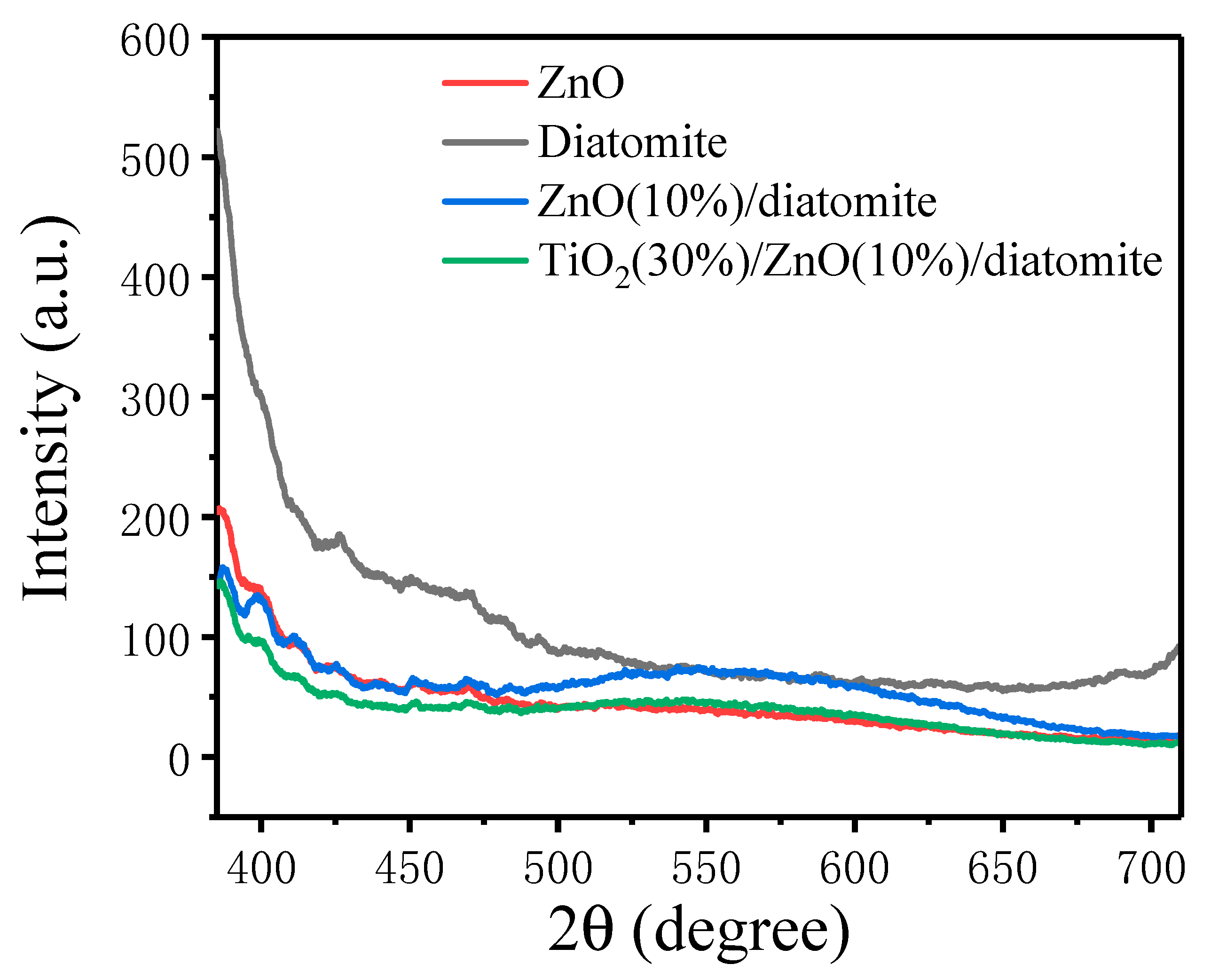
2.6. Photoluminescence (PL) Spectra

Fluorescence spectra reflect the recombination proportion of photogenerated electron–hole pairs in a catalyst [27,28]. Generally, a weaker fluorescence intensity corresponds to a lower recombination proportion of photogenerated electron–hole pairs, which facilitates the photocatalytic reaction. As shown in Figure 6, the TiO2(30%)/ZnO(10%)/diatomite composite catalyst had a lower fluorescence intensity compared to diatomite, ZnO, and ZnO(10%)/diatomite. The excitation wavelength was 320 nm. Therefore, it should have the lowest recombination proportion of photogenerated electron–hole pairs and the highest photocatalytic efficiency [29,30,31].

2.7. Photocatalytic Performance of Different Catalysts

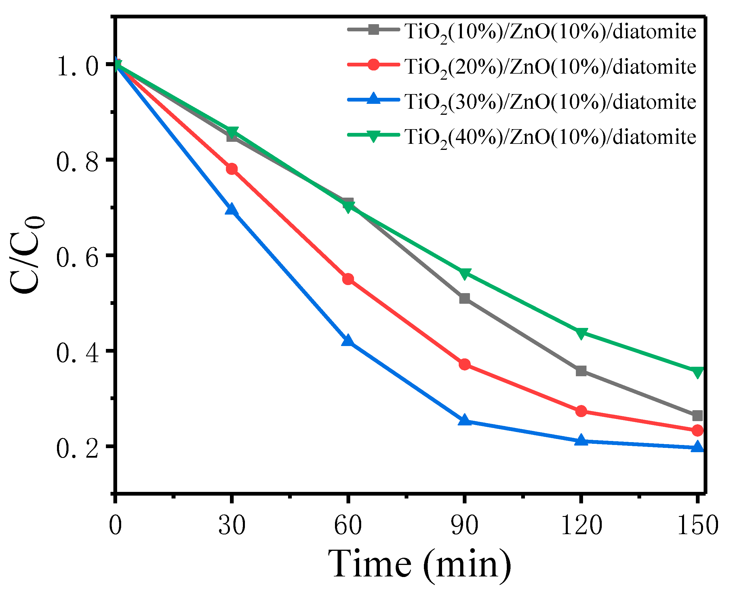
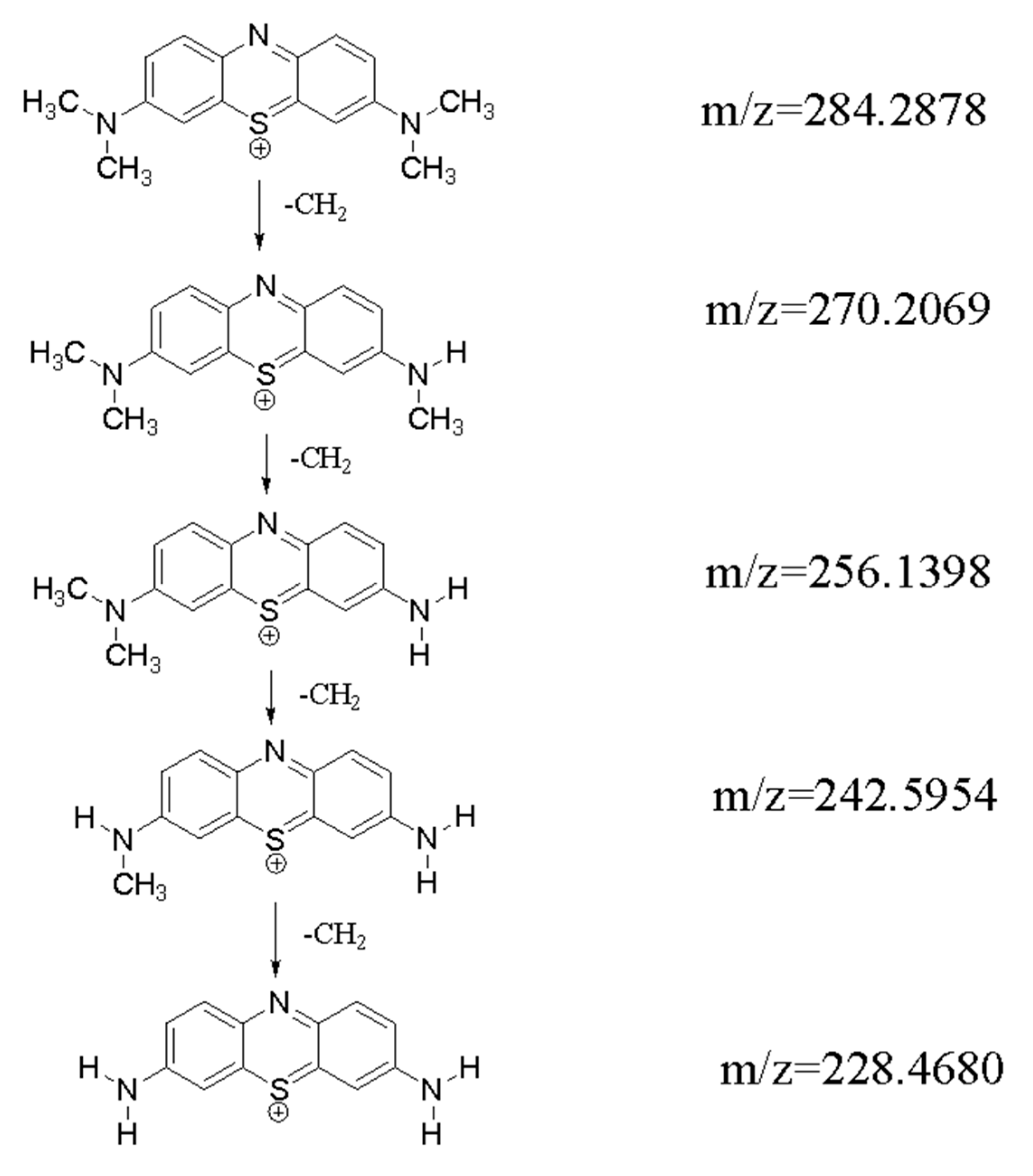
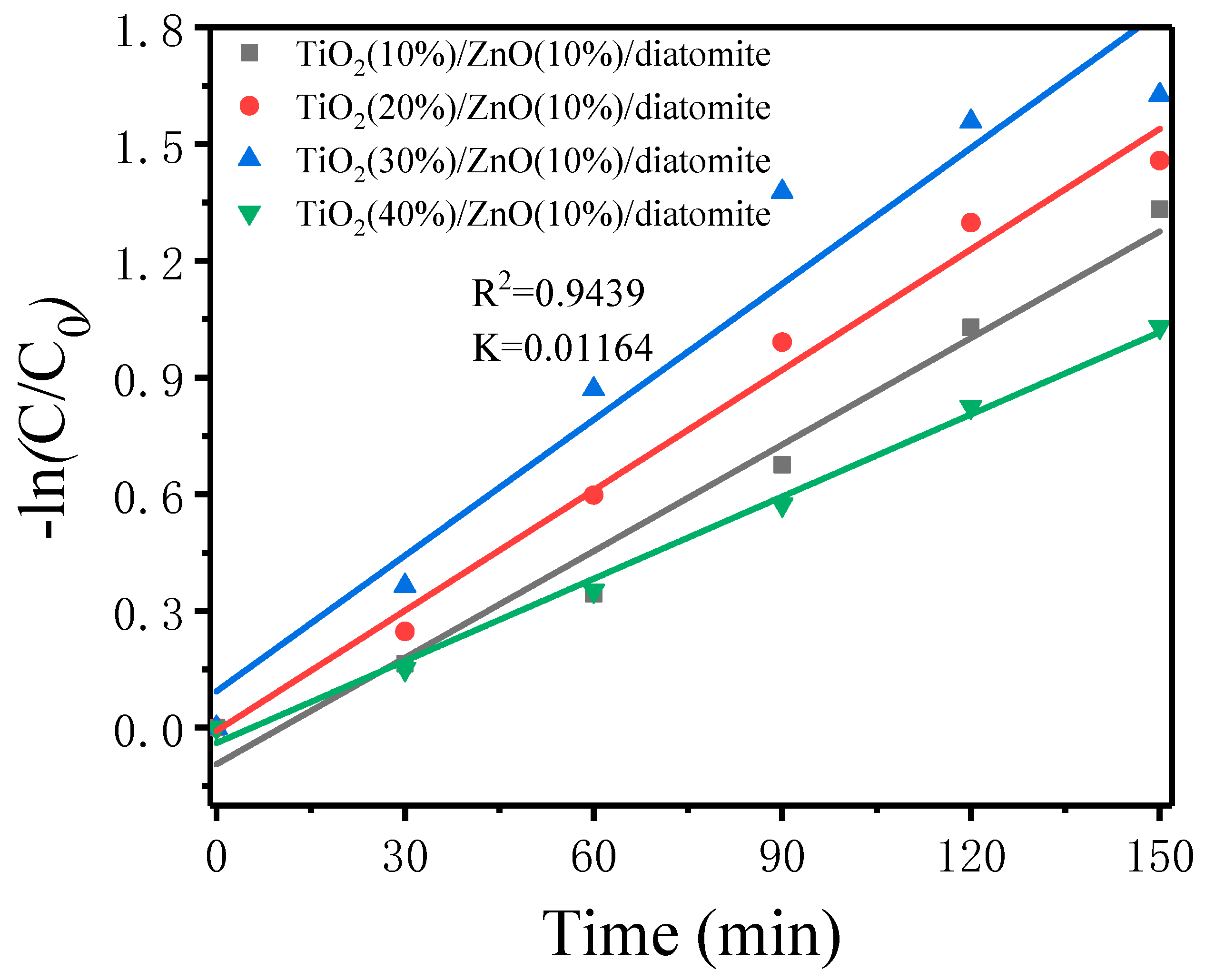
2.7.1. Photocatalytic Degradation of MB by Different Catalysts

Figure 7 illustrates the formation of TiO2(30%)/ZnO(10%)/diatomite, and as shown in Figure 8, the degradation efficiency of MB varied with the proportion of TiO2 in the composite catalyst. The degradation rate of MB for TiO2(30%)/ZnO(10%)/diatomite was 80.34% after 3 h of light exposure, which was superior to that of the other composites with different proportions of TiO2. In addition, the degradation proportion of the MB solution during the initial stage of illumination increased with the increasing illumination time, and the removal rate of MB also increased. Over time, the MB removal rate remained relatively stable. This may be due to the continuous increase in oxygen vacancies and free electrons during the reaction process with the increasing illumination time and to the continuous adsorption, oxidation, re-adsorption, and re-oxidation on the catalysts surface, which increased the effective surface area of the catalyst and maintained more catalytic active sites, resulting in a high oxidation efficiency.
The data in Figure 8 were fitted using linear equations to determine whether the reactions followed first-order kinetics, and the results are shown in Figure 9. As shown in Figure 9, the photocatalytic process of the composite catalysts containing different proportions of TiO2 followed first-order reaction kinetics. After fitting the data, the linear slope (k, first-order kinetic constant of the photocatalytic process independent of the adsorbed phase) was obtained, which was 0.01164 for the TiO2(30%)/ZnO(10%)/diatomite composite. To further study the degradation mechanism of MB, the reaction products of MB at different reaction times were analyzed by liquid chromatography–mass spectrometry (LCMS). Figure 10 shows the liquid-phase mass spectrum of the degradation products of MB, and the data analysis is shown in Figure 11.

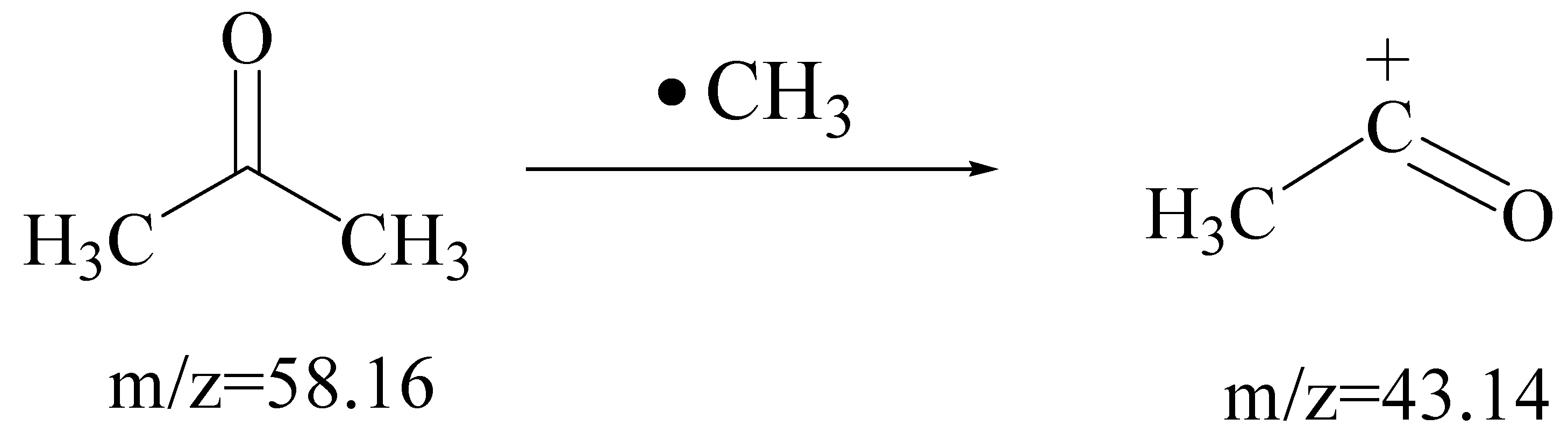
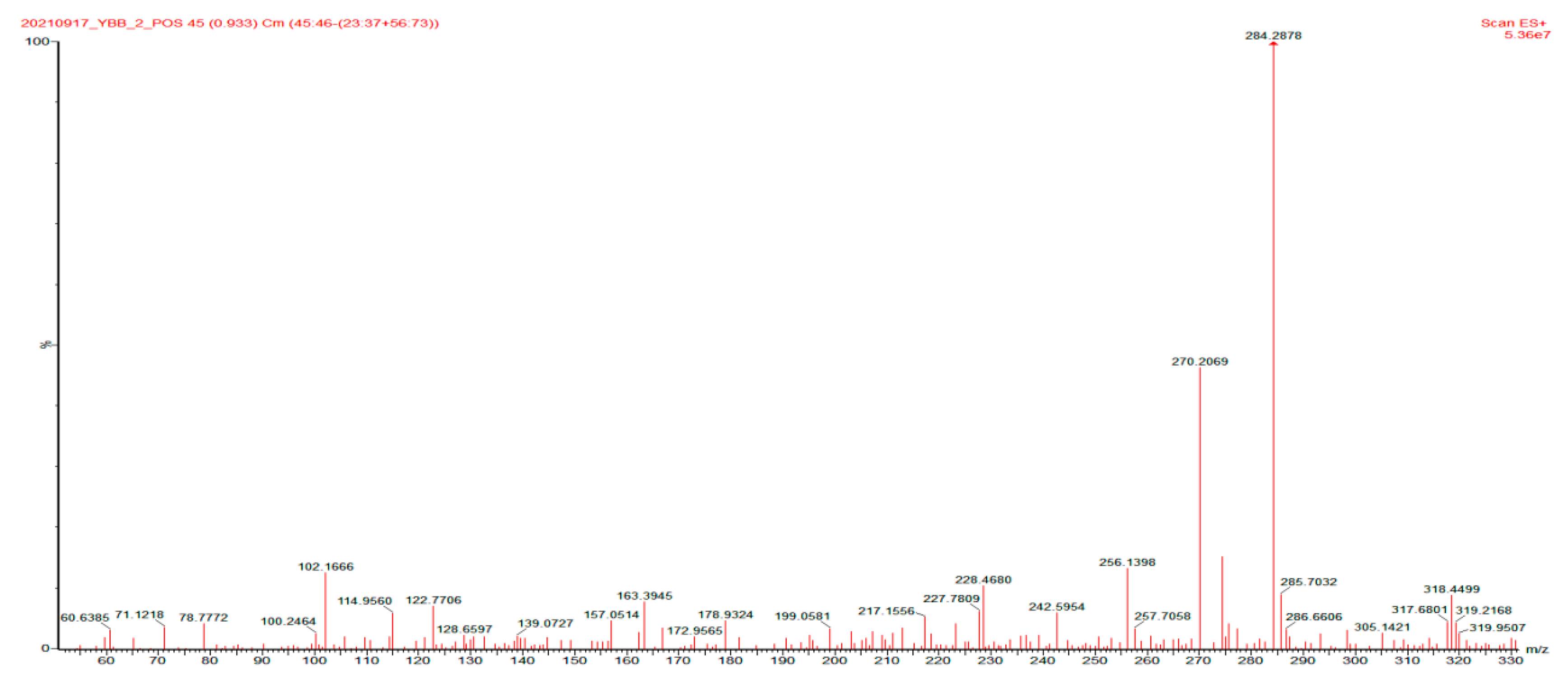
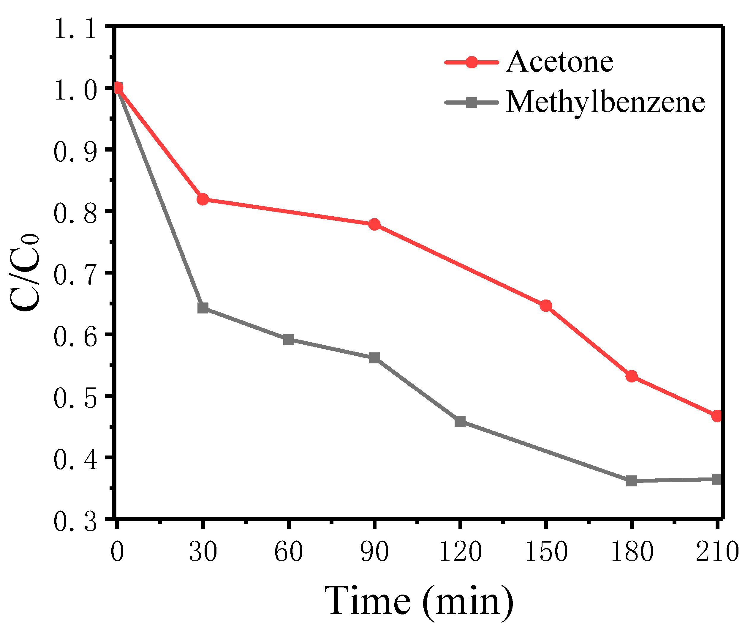
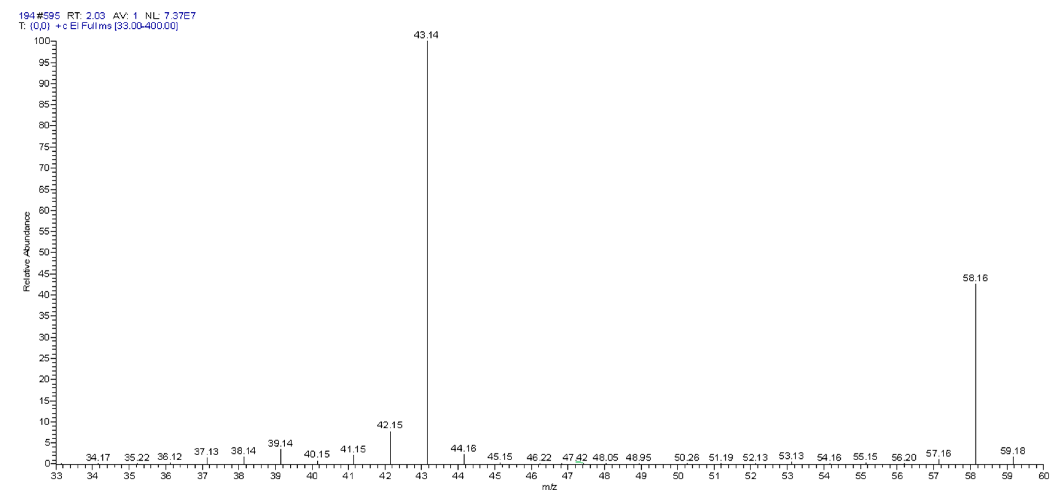
2.7.2. Photocatalytic Degradation of Gaseous Methylbenzene and Gaseous Acetone over TiO2(30%)/ZnO(10%)/Diatomite

Figure 12 shows the photodegradation for gaseous methylbenzene and gaseous acetone. At room temperature, the gas concentration was ruled by adding 1 mL of saturated gas to headspace vials. As shown in Figure 12, under visible light irradiation, TiO2(30%)/ZnO(10%)/diatomite demonstrated excellent photocatalytic degradation performance for gaseous methylbenzene and gaseous acetone. Furthermore, gaseous methylbenzene and gaseous acetone were substantially degraded after 210 min of illumination, with degradation efficiencies of 63.5% and 53.3%, respectively. The degradation efficiency of gaseous methylbenzene was higher than that of gaseous acetone. However, because of the high initial concentration, they were not completely degraded during the short test time. Based on the analysis of the degradation results, one possible reason was that the structures of gaseous methylbenzene and gaseous acetone were relatively stable and difficult to destroy. In this study, the photodegradation products of gaseous acetone were studied by gas chromatography–mass spectrometry (GC-MS). According to the GC-MS analysis (Figure 13 and Figure 14), CH3CO+ was present in the gaseous acetone degradation product. This discovery has the guiding significance for the subsequent degradation of other gaseous organic pollutants. The catalytic degradation and products of other gaseous organic pollutants and further analyses of the degradation path and mechanism will be studied in the days to come.

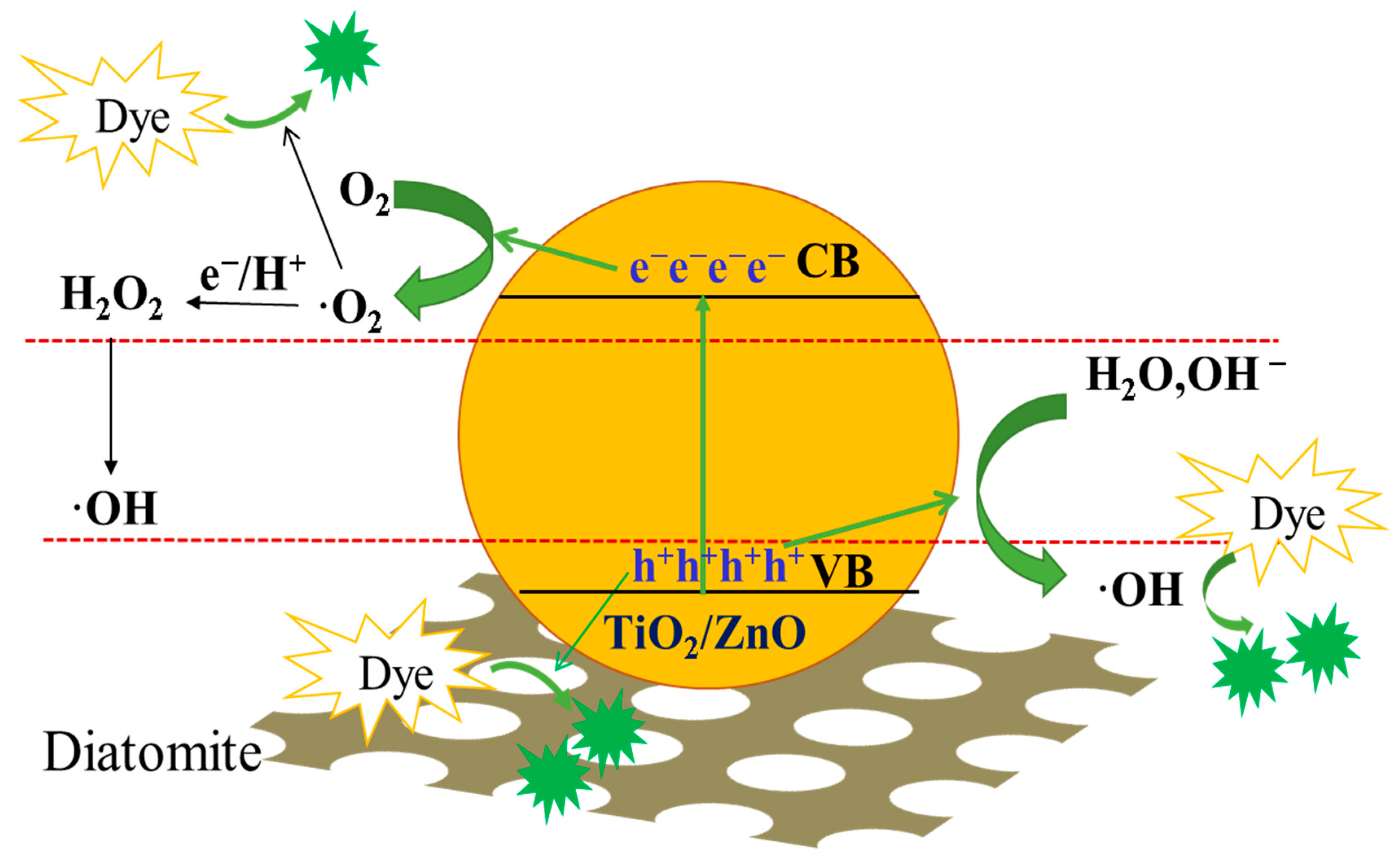
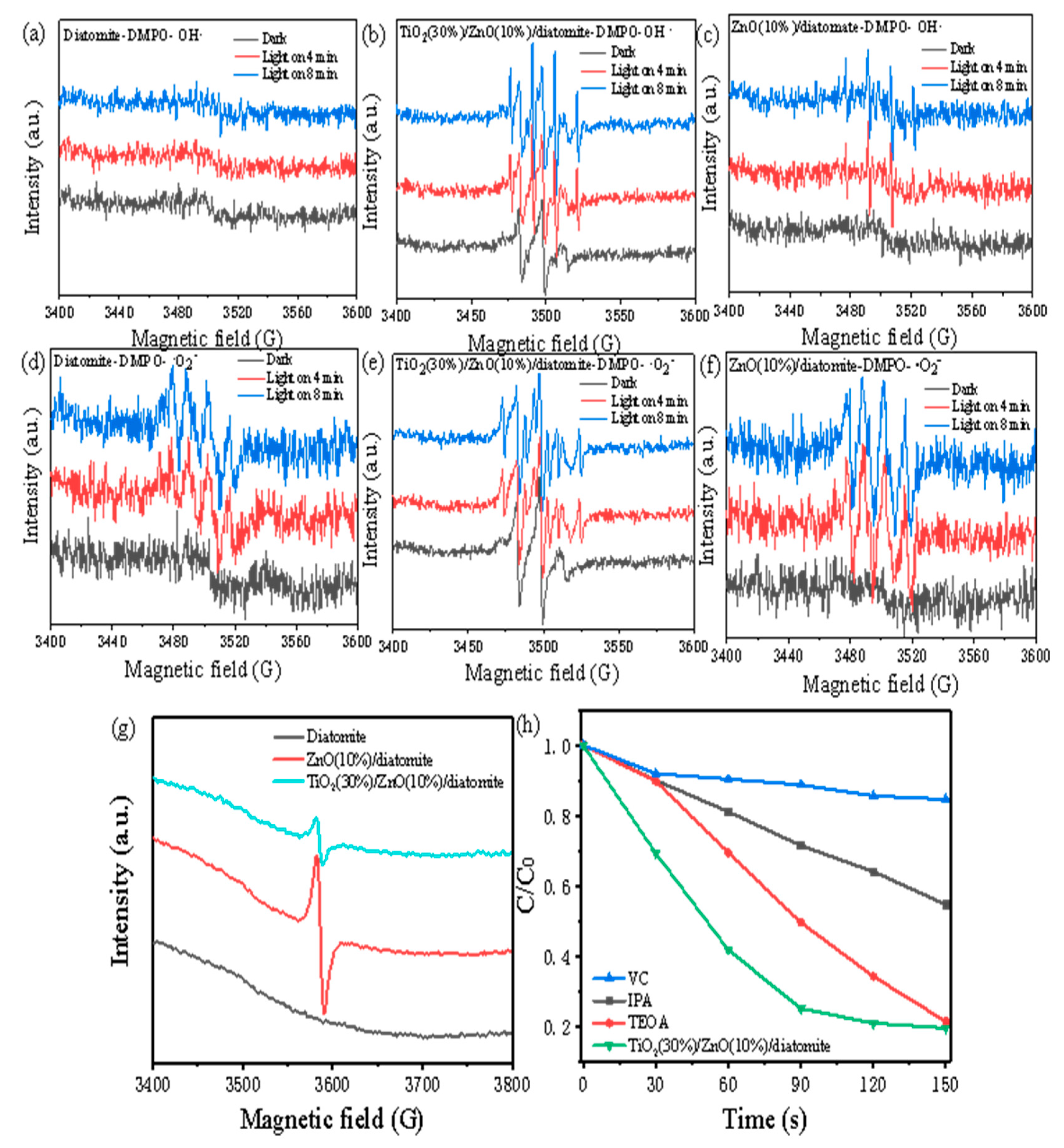
2.7.3. Analysis of the Photocatalytic Mechanism

The photocatalytic degradation of MB involves nine steps. When the photocatalyst is excited by visible light, the first step is exciting electrons into the conduction band, which leaves an equal number of holes in the valence band, as shown in Figure 15. Electrons and holes generated in an aqueous medium convert hydroxyl and superoxide into free radicals with a high oxidation performance. These free radicals react with the organic compounds to produce the final product. The specific reaction processes are as follows.
TiO2(X%)/ZnO(10%)/diatomite + hv → TiO2(X%)/ZnO(10%)/diatomite (h+) + TiO2(X%)/ZnO(10%)/diatomite (e)
H2O + TiO2(X%)/ZnO(10%)/diatomite (h+) → ·OH + H+
O 2 + TiO 2 ( X % ) / ZnO ( 10 % ) / diatomite   ( e )   TiO 2 ( X % ) / ZnO ( 10 % ) / diatomite   ( · O 2 )
TiO 2 ( X % ) / ZnO ( 10 % ) / diatomite   ( · OH ) + MB     H 2 O + CO 2
TiO 2 ( X % ) / ZnO ( 10 % ) / diatomite   ( · O 2 ) + MB     H 2 O + CO 2
H + + TiO 2 ( X % ) / ZnO ( 10 % ) / diatomite   ( · O 2 )     TiO 2 ( X % ) / ZnO ( 10 % ) / diatomite   ( · OOH )
TiO2(X%)/ZnO(10%)/diatomite (·OOH) + TiO2(X%)/ZnO(10%)/diatomite (·OOH) → O2 + H2O2
H2O2 + TiO2(X%)/ZnO(10%)/diatomite (e)→ TiO2(X%)/ZnO(10%)/diatomite (OH) + TiO2(X%)/ZnO(10%)/diatomite (·OH)
TiO 2 ( X % ) / ZnO ( 10 % ) / diatomite   ( · OH ,   · O 2 ,   h + ) + MB   CO 2 + H 2 O + inorganic   compounds

2.8. Electron Paramagnetic Resonance (EPR) Analysis

Three main active substances participate in the photodegradation of MB: photoexcited holes (h+), hydroxyl radicals (·OH), and superoxide radicals ( · O 2 ). To investigate the mechanisms of the photocatalytic step, triethanolamine (TEOA) was used to capture   h + , isopropanol (IPA) was used to capture ·OH, and ascorbic acid (VC) was used to capture · O 2 . The captured amount was 1 mmol and the results are shown in Figure 16h. Under visible light conditions, the degradation proportion of the MB solution without free radical scavengers was 80.34%, while the degradation proportion of the experimental groups with the free radical scavengers decreased by different degrees, with TEOA at 78.50%, IPA at 45.20%, and VC at 15.29%. Based on these results, the influence of the active species on the photocatalytic MB solution followed the order h + < ·OH < · O 2 . The photocatalytic properties of the material were closely related to the number of active species produced in the reaction system; therefore, EPR was used to characterize the h + , ·OH, and · O 2 . Figure 16a–g shows the signals from the active species h + , ·OH, and · O 2 . After irradiation with a xenon lamp, the signal intensity of all the active species increased as the xenon lamp exposure time increased. When the catalysts were irradiated by a xenon lamp for 4 or 8 min, the TiO2(30%)/ZnO(10%)/diatomite catalyst had the biggest ·OH signal (Figure 16a–c) and the strongest O 2 signal (Figure 16d–f). However, the oxygen vacancy defect test results in Figure 16g showed that the number of oxygen vacancy defects in TiO2(30%)/ZnO(10%)/diatomite was lower than that in ZnO(10%)/diatomite, indicating that the photocatalytic degradation of MB was more closely related to · O 2 and ·OH.

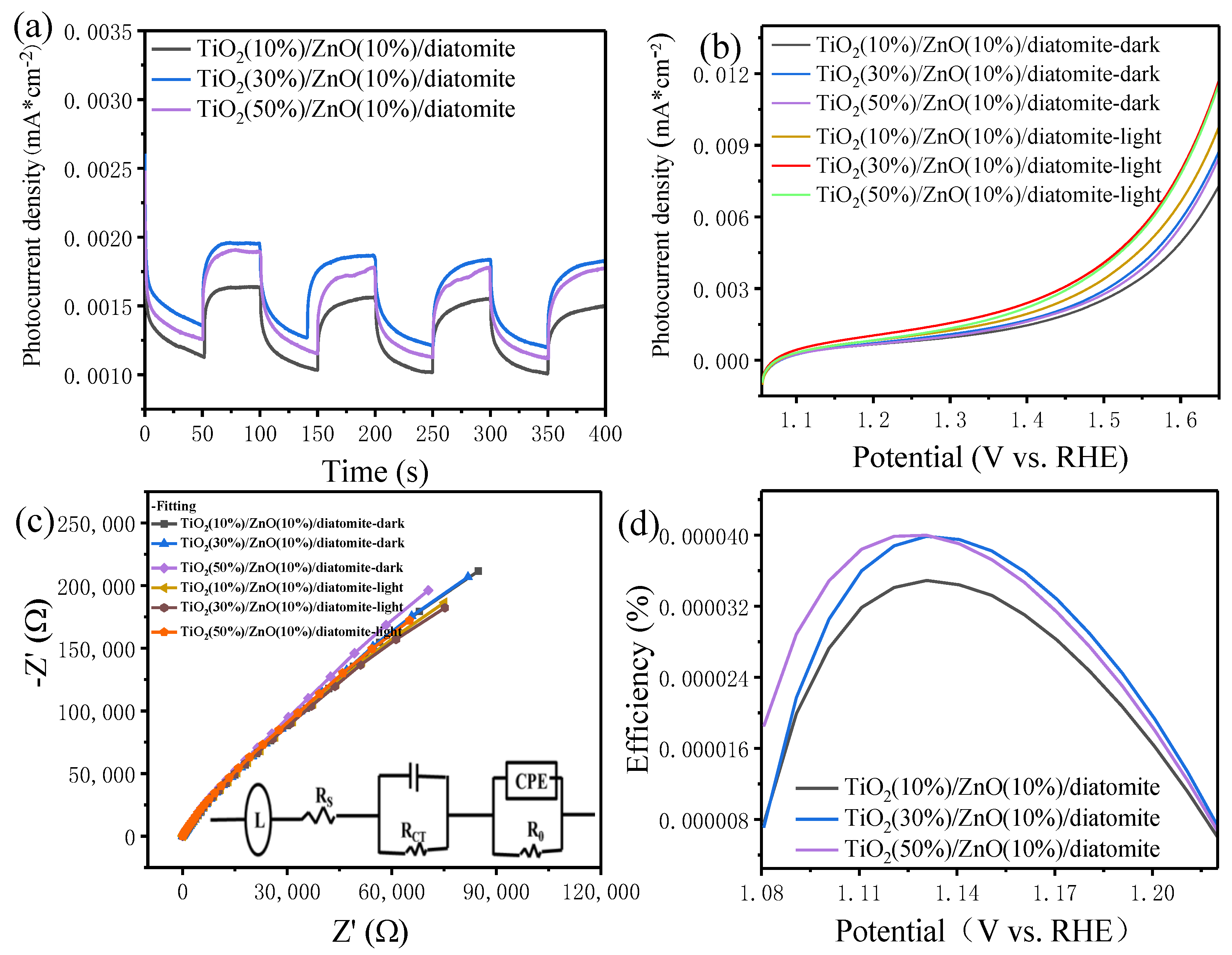
2.9. Photocurrent Analysis

Figure 17a shows the photocurrent–time curves of the TiO2(X%)/ZnO(10%)/diatomite catalysts in truncated light with +0.8 V vs. RHE for ≥400 s and an on/off cycle of 50 s. While the lamp was turned off (dark condition), all the photoanodes displayed a lower photocurrent density of nearing 0.0015 mA/cm2. Under illumination, there were distinct photoresponse plateaus with a large and glossy photocurrent, indicating the fast separation of photogenerated electrons. This result showed that the catalyst with a 30% molar loading ratio had the fastest light feedback and reproduced an equal photoresponse over 400 s, indicating it had more photogenerated electron–hole pairs and a lower recombination rate.
The composites with various loading ratios were investigated to determine the maximum photocurrent density, as shown in Figure 17b. A comparison between dark and light conditions revealed that the photocurrent concentration under light conditions was substantially larger than that under dark conditions. The composite with a 30% molar loading ratio had the largest photocurrent concentration among the composite catalysts because of the charge collection performance and direct path to photoelectrons.
The charge transfer resistance was analyzed by an electrochemical impedance spectroscopy (EIS) of the catalysts at 0.1 V. Generally, the charge transfer resistance is represented by a semicircle at intermediate frequencies, where a larger diameter corresponds to a larger charge transfer resistance. The EIS data could be fitted to characterize the electrode–catalyst–electrolyte interface. An equivalent circuit (inset of Figure 17c) was used, which included the typical electrical elements. The inductance of an external circuit (L), uncompensated solution resistance (Rs), charge transfer resistance (RCT), contact resistance between the catalyst and the glassy carbon electrode (R0), and the constant phase elements (CPE) of the double-layer capacitor were required for fitting. RS was the same for all electrodes, indicating a fair comparison, while the smallest RCT value was obtained for the catalyst with a 30% molar loading ratio, indicating the fastest charge transfer.
Figure 17d shows the performance diagrams of the composites with various loading proportions for photoelectrochemical water splitting. The performance of the catalyst with a 30% molar loading ratio was clearly larger than that of the others, meaning that the Si–O–Zn bonds were favorable to the transmission of electrons and enhanced the performance of photoelectrochemical water splitting.

3. Experimental Section

3.1. Chemicals and Materials

Diatomite (Macklin, Shanghai, China), zinc acetate dihydrate (Zn(OOCCH3)2·2H2O, Alfa Aesar, Shanghai, China), titanium tetrachloride (analytical reagent, Beijing, China), ammonia water (analytical reagent, Beijing, China), polyvinylpyrrolidone (PVP, analytical reagent, Beijing, China), hexadecyl trimethyl ammonium bromide (CTAB, analytical reagent, Beijing, China), acetylacetone (analytical reagent, Tianjin, China), acetone (analytical reagent, Beijing, China), methylbenzene (Aladdin, Shanghai, China), methylbenzene (analytical reagent, Beijing, China), tetraethyl orthosilicate (analytical reagent, Beijing, China), ethanol absolute (analytical reagent, Beijing, China), and deionized water were used for the synthesis of TiO2(X%)/ZnO(10%)/diatomite. During the synthesis of TiO2(X%)/ZnO(10%)/diatomite, all reagents listed were purchased and used without further treatment.

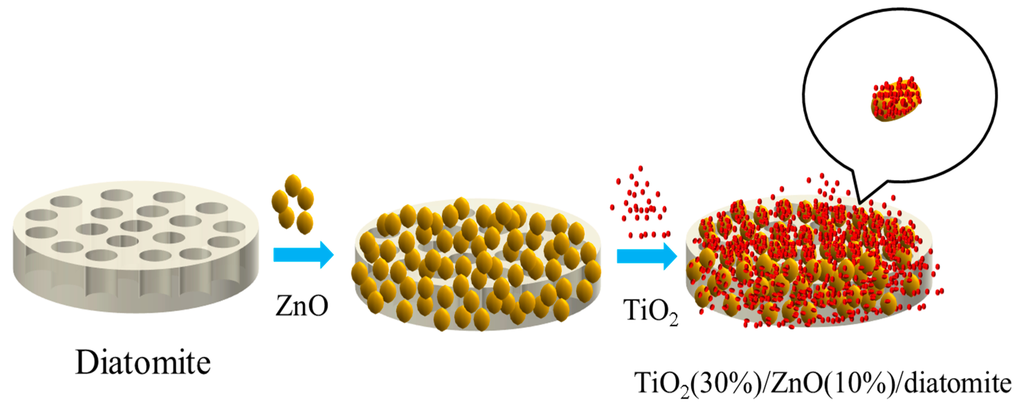
3.2. Catalyst Preparation

3.2.1. Synthesis of ZnO(10%)/Diatomite

In our previous work, we found that the ZnO(10%)/diatomite composite catalyst had the best photocatalytic performance [32]. Therefore, it was selected as the carrier in this study. In a typical procedure, diatomite (20 g) was added to deionized water (40 mL). After the solution was magnetically stirred in an ice-water bath for 30 min, Zn(OOCCH3)2·2H2O (5.38 g) was added and stirred for an additional 30 min. Then, acetylacetone (2 mL) and the 0.3% ammonia solution were added dropwise until the pH of the solution was 10.00. The solution was then heated in a water bath under 75 °C for 7 h, and ZnO(10%)/diatomite was produced.

3.2.2. Synthesis of TiO2(X%)/ZnO(10%)/Diatomite

ZnO(10%)/diatomite (1 g) was added to ethanol absolute (15 mL). After the solution became uniform, CTAB (0.2 mL) and PVP (0.2 mL) were added and stirred for 15 min. Titanium tetrachloride (molar ratio), ethanol absolute (10 mL), and tetraethyl orthosilicate (0.005 mL) were successively added in an ice-water bath. After stirring for 2 h in a 50 °C water bath and for 2 h in an 80 °C water bath, the precipitate was sequentially centrifuged with deionized water four times, then dried at room temperature for 12 h. TiO2(X%)/ZnO(10%)/diatomite was produced.

4. Characterization

4.1. Material Characterization

The phases in the synthesized samples were analyzed using XRD with Cu Kα radiation at a scan rate of 5°/min in the 2θ range 3°–90°. The particle sizes and morphologies of the products were examined using SEM (S-4700 and JSM-7800F, Japan) with EDS. The UV–vis absorbance was measured using a UV–VISNIR spectrophotometer (SolidSpec-3700, Shimadzu, Japan). PL spectroscopy (FL-7000, Hitachi, Japan) was serviced to evaluate the photocatalytic activity. An XPS analysis was performed to examine the elemental chemical environment. EPR (EMX-500 10/12) was used to reveal unpaired electrons in atoms or molecules qualitatively and quantitatively and to explore the structural properties of their surroundings. A CHI660E electrochemical analyzer was serviced at room temperature in a 0.5 M Na2SO4 solution with a traditional three-electrode system. A glassy carbon electrode was used as the working electrode, a calomel electrode was serviced as the reference electrode, and a graphite electrode was serviced as the counter electrode.

4.2. Photocatalytic Activity

The photocatalytic activity of the products was evaluated using the MB solution photocatalytic degradation method. The degradation process for the catalyst was as follows. The sample (5 mg) was dispersed in the MB solution (30 mL), which was then placed in a xenon lamp box. The mixture was then subjected to dark conditions for 30 min. Then, 4 mL of the mixture was placed in a sample tube and marked as serial number one. The xenon lamp was then turned on, and 4 mL of the solution was removed every 30 min and marked as 2–6, sequentially. The degradation rate was determined by monitoring the variation in the MB concentration over time using a UV–Vis spectrophotometer.
The catalyst with the highest degradation proportion was selected to degrade gaseous organic pollutants, including gaseous methylbenzene and gaseous acetone. In the sealed conditions, the saturated gas had the same concentration as that of the liquid. The degradation process for the target was as follows: the catalyst (0.15 g) was placed into a headspace vial (250 mL capacity), and the saturated gas pollutant (1 mL) was injected into the headspace vial using a gas chromatography syringe (2.5 mL capacity). In the process of photocatalytic degradation, a xenon lamp (30 W) was used as the light source. We placed the headspace vial under light and directly irradiated it. The entire process was conducted in room temperature, and without heating or stirring performed throughout the degradation process. Gas was collected every half an hour, and the corresponding concentrations of organic gas pollutants were examined by GC–MS.

4.3. Electrochemical Measurements of the Electrocatalysts

The photoelectrochemical water splitting activity of the catalysts was determined with a three-electrode system using a CHI electrochemical workstation (model 660E). A glassy carbon electrode (diameter: 5 mm, 0.1256 cm2) was used as the working electrode, a Hg/HgO electrode was used as the reference electrode, and a graphite electrode was used as the counter electrode. The efficiency of photoelectrochemical water splitting was calculated using the following formula:
η (%) = J (1.23 − ERHE)/Ilight
where η (%) represents the efficiency of photoelectrochemical water splitting, ERHE represents the potential calibrated against RHE, and Ilight represents the photocurrent density. The preparation process for the electrocatalyst was as follows: The sample (10 mg) was dispersed in water/ethanol absolute (0.95 mL, 1:1 v/v). Nafion (30 μL, 5 wt%) was then added to the solution to obtain a homogeneous ink. The mixture was ultrasonically dispersed for 10 min. Then, 5 μL of the uniform mixture was extracted and dropped onto the surface of the glassy carbon electrode. Photoelectrochemical tests were performed in 0.5 M Na2SO4 (pH = 7.00). Linear sweep voltammetry (LSV) was conducted in the 0.5 M Na2SO4 (pH = 7.00) at a scan rate of 5 mV/s. EIS was performed in the potentiostatic mode from 105 to 0.1 Hz.

5. Conclusions

In this study, TiO2(X%)/ZnO(10%)/diatomite composite catalysts were successfully prepared via a two-step precipitation method using titanium tetrachloride and zinc acetate dihydrate in an ice-water bath. During the reaction, the ZnO nanoparticles were coated on diatomite in an ice-water bath, and TiO2 was uniformly coated on the surface of ZnO and diatomite. Furthermore, the large pore structures and hydroxyl groups of the diatomite easily bonded with ZnO and TiO2. Owing to the interaction between ZnO and TiO2 and its combination with diatomite, ZnO and TiO2 not only improved the original visible-light absorption performance, but also greatly enhanced the ultraviolet light absorption performance. The TiO2(30%)/ZnO(10%)/diatomite catalyst exhibited a considerably higher catalytic efficiency of 80.34% after 150 min of adsorption and photodegradation of MB, and the degradation process of MB was determined by LCMS. In addition, the composite catalyst had a strong degradation potential for gaseous methylbenzene and gaseous acetone. After 210 min of adsorption and photodegradation, the catalytic efficiencies were 63.5% and 53.3%, respectively. CH3CO+ was detected in gaseous acetone degradation products by GC-MS. For photoelectrochemical water splitting, the composite catalysts exhibited a good photoresponsivity and excellent electrolytic efficiency. This was mainly because the composite system produced more photogenerated electron–hole pairs under visible light and had a lower recombination rate, providing a longer survival time. In addition, the composite catalysts had more active species, such as oxygen vacancies, hydroxyl radicals, and superoxide radicals, providing a higher catalytic capacity.

Author Contributions

Conceptualization, B.Y. and J.Y.; methodology, B.Y.; software, B.Y. and Q.W.; validation, B.Y. and Z.M.; formal analysis, B.Y.; investigation, B.Y.; resources, B.Y.; data curation, B.Y.; writing—original draft preparation, B.Y.; writing—review and editing, B.Y. and J.Y.; visualization, B.Y. and J.Y.; supervision, J.Y.; project administration, J.Y.; funding acquisition, J.Y. All authors have read and agreed to the published version of the manuscript.

Funding

This research received no external funding.

Conflicts of Interest

The authors declare no conflict of interest.

References

  1. Liang, L.; Meng, Y.; Shi, L.; Ma, J.; Sun, J. Enhanced photocatalytic performance of novel visible light-driven Ag–TiO2/SBA-15 photocatalyst. Superlattices Microstruct. 2014, 73, 60–70. [Google Scholar] [CrossRef]
  2. Pant, B.; Park, M.; Park, S.J. Recent advances in TiO2 films prepared by sol-gel methods for photocatalytic degradation of organic pollutants and antibacterial activities. Coatings 2019, 9, 613. [Google Scholar] [CrossRef] [Green Version]
  3. Ajmal, A.; Majeed, I.; Malik, R.N.; Idriss, H.; Nadeem, M.A. Principles and mechanisms of photocatalytic dye degradation on TiO2 based photocatalysts: A comparative overview. RSC Adv. 2014, 4, 37003–37026. [Google Scholar] [CrossRef]
  4. Singh, J.; Kumar, S.; Rishikesh Manna, A.K.; Soni, R.K. Fabrication of ZnO–TiO2 nanohybrids for rapid sunlight driven photodegradation of textile dyes and antibiotic residue molecules. Opt. Mater. 2020, 107, 110138. [Google Scholar] [CrossRef]
  5. Pant, B.; Ojha, G.P.; Kuk, Y.S.; Kwon, O.H.; Park, Y.W.; Park, M. Synthesis and characterization of ZnO-TiO2/carbon fiber composite with enhanced photocatalytic properties. Nanomaterials 2020, 10, 1960. [Google Scholar] [CrossRef]
  6. Dong, H.; Zeng, G.; Tang, L.; Fan, C.; Zhang, C.; He, X.; He, Y. An overview on limitations of TiO2-based particles for photocatalytic degradation of organic pollutants and the corresponding countermeasures. Water Res. 2015, 79, 128–146. [Google Scholar] [CrossRef]
  7. Johar, M.A.; Afzal, R.A.; Alazba, A.A.; Manzoor, U. Photocatalysis and bandgap engineering using ZnO nanocomposites. advances in materials science and engineering. Adv. Mater. Sci. Eng. 2015, 2015, 1–22. [Google Scholar] [CrossRef] [Green Version]
  8. Firdaus, C.M.; Rizam, M.S.B.S.; Rusop, M.; Hidayah, S.R. Characterization of ZnO and ZnO: TiO2 thin films prepared by sol-gel spray-spin coating technique. Procedia Eng. 2012, 41, 1367–1373. [Google Scholar] [CrossRef]
  9. Kiziltaş, H.; Tekin, T. Increasing of photocatalytic performance of TiO2 nanotubes by doping AgS and CdS. Chem. Eng. Commun. 2017, 204, 852–857. [Google Scholar] [CrossRef]
  10. Chen, Y.; Zhang, C.; Huang, W.; Situ, Y.; Huang, H. Multimorphologies nano-ZnO preparing through a simple solvothermal method for photocatalytic application. Mater. Lett. 2015, 141, 294–297. [Google Scholar] [CrossRef]
  11. Colmenares, J.C.; Kuna, E.; Jakubiak, S.; Michalski, J.; Kurzydłowski, K. Polypropylene nonwoven filter with nanosized ZnO rods: Promising hybrid photocatalyst for water purification. Appl. Catal. B Environ. 2015, 170, 273–282. [Google Scholar] [CrossRef]
  12. Malakooti, M.H.; Hwang, H.S.; Sodano, H.A. Morphology-controlled ZnO nanowire arrays for tailored hybrid composites with high damping. ACS Appl. Mater. Interfaces 2015, 7, 332–339. [Google Scholar] [CrossRef] [PubMed]
  13. Hou, X.; Stanley, S.L.; Zhao, M.; Zhang, J.; Zhou, H.; Cai, Y.; Huang, F.; Wei, Q. MOF-based C-doped coupled TiO2/ZnO nanofibrous membrane with crossed network connection for enhanced photocatalytic activity. J. Alloys Compd. 2019, 777, 982–990. [Google Scholar] [CrossRef]
  14. Liu, J.; Wang, P.; Qu, W.; Li, H.; Shi, L.; Zhang, D. Nanodiamond-decorated ZnO catalysts with enhanced photocorrosion-resistance for photocatalytic degradation of gaseous toluene. Appl. Catal. B Environ. 2019, 257, 117880. [Google Scholar] [CrossRef]
  15. Rachna, R.M.; Shanker, U. Sunlight assisted degradation of toxic phenols by zinc oxide doped prussian blue nanocomposite. J. Environ. Chem. Eng. 2020, 8, 104040. [Google Scholar] [CrossRef]
  16. Potle, V.D.; Shirsath, S.R.; Bhanvase, B.A.; Saharan, V.K. Sonochemical preparation of ternary rGO-ZnO-TiO2 nanocomposite photocatalyst for efficient degradation of crystal violet dye. Optik 2020, 208, 164555. [Google Scholar] [CrossRef]
  17. Viet, T.Q.Q.; Khoi, V.H.; Giang, N.T.H.; Van Anh, H.T.; Dat, N.M.; Phong, M.T.; Hieu, N.H. Statistical screening and optimization of photocatalytic degradation of methylene blue by ZnO–TiO2/rGO nanocomposite. Colloids Surf. A Physicochem. Eng. Asp. 2021, 629, 127464. [Google Scholar] [CrossRef]
  18. Zhao, Y.; Tian, G.; Duan, X.; Liang, X.; Meng, J.; Liang, J. Environmental applications of diatomite minerals in removing heavy metals from water. Ind. Eng. Chem. Res. 2019, 58, 11638–11652. [Google Scholar] [CrossRef]
  19. Li, Q.; Zhai, G.; Xu, Y.; Odoom-Wubah, T.; Jia, L.; Huang, J.; Sun, D.; Li, Q. Diatomite supported Pt nanoparticles as efficient catalyst for benzene removal. Ind. Eng. Chem. Res. 2019, 58, 14008–14015. [Google Scholar] [CrossRef]
  20. Wang, B.; Li, F.; Yang, P.; Yang, Y.; Hu, J.; Wei, J.; Yu, Q. In situ synthesis of diatomite–carbon nanotube composite adsorbent and its adsorption characteristics for phenolic compounds. J. Chem. Eng. Data 2018, 64, 360–371. [Google Scholar] [CrossRef]
  21. Sun, Q.; Li, H.; Zheng, S.; Sun, Z. Characterizations of nano-TiO2/diatomite composites and their photocatalytic reduction of aqueous Cr (VI). Appl. Surf. Sci. 2014, 311, 369–376. [Google Scholar] [CrossRef]
  22. Xiao, L.; Pang, B. Preparation of diatomite supported nano zinc oxide composite photocatalytic material and study on its formaldehyde degradation. IOP Conf. Ser. Mater. Sci. Eng. 2017, 242, 012016. [Google Scholar] [CrossRef]
  23. Vasilaki, E.; Katsarakis, N.; Dokianakis, S.; Vamvakaki, M. rGO functionalized ZnO–TiO2 core-shell flower-like architectures for visible light photocatalysis. Catalysts 2021, 11, 332. [Google Scholar] [CrossRef]
  24. Hua, C.; Liu, X.; Ren, S.; Zhang, C.; Liu, W. Preparation of visible light-responsive photocatalytic paper containing BiVO4@diatomite/MCC/PVBCFs for degradation of organic pollutants. Ecotoxicol. Environ. Saf. 2020, 202, 110897. [Google Scholar] [CrossRef] [PubMed]
  25. Xiong, C.; Ren, Q.; Liu, X.; Jin, Z.; Ding, Y.; Zhu, H.; Li, J.; Chen, R. Fenton activity on RhB degradation of magnetic g-C3N4/diatomite/Fe3O4 composites. Appl. Surf. Sci. 2021, 543, 148844. [Google Scholar] [CrossRef]
  26. Liu, X.; He, Y.; Yang, B.; Yan, Q.; Yang, J. Highly efficient photo-degradation of gaseous organic pollutants catalyzed by diatomite-supported titanium dioxide. Catalysts 2020, 10, 380. [Google Scholar] [CrossRef] [Green Version]
  27. Wu, L.; Zhou, Y.; Nie, W.; Song, L.; Chen, P. Synthesis of highly monodispersed teardrop-shaped core–shell SiO2/TiO2 nanoparticles and their photocatalytic activities. Appl. Surf. Sci. 2015, 351, 320–326. [Google Scholar] [CrossRef]
  28. Yu, X.; Zhao, Z.; Zhang, J.; Guo, W.; Li, L.; Liu, H.; Wang, Z.L. One-step synthesis of ultrathin nanobelts-assembled urchin-like anatase TiO2 nanostructures for highly efficient photocatalysis. CrystEngComm 2017, 19, 129–136. [Google Scholar] [CrossRef]
  29. Najibi Ilkhechi, N.; Mozammel, M.; Yari Khosroushahi, A. Antifungal effects of ZnO, TiO2 and ZnO-TiO2 nanostructures on Aspergillus flavus. Pestic. Biochem. Physiol. 2021, 176, 104869. [Google Scholar] [CrossRef]
  30. Wang, Y.; Liu, X.; Guo, L.; Shang, L.; Ge, S.; Song, G.; Naik, N.; Shao, Q.; Lin, J.; Guo, Z. Metal organic framework-derived C-doped ZnO/TiO2 nanocomposite catalysts for enhanced photodegradation of Rhodamine B. J. Colloid Interface Sci. 2021, 599, 566–576. [Google Scholar] [CrossRef]
  31. Tyagi, J.; Gupta, H.; Purohit, L.P. Mesoporous ZnO/TiO2 photoanodes for quantum dot sensitized solar cell. Opt. Mater. 2021, 115, 111014. [Google Scholar] [CrossRef]
  32. Yang, B.; Liu, X.; Ma, Z.; Wang, Q.; Yang, J. Synthesis of nano-ZnO/diatomite composite and research on photoelectric application. Catalysts 2021, 11, 1232. [Google Scholar] [CrossRef]
Figure 1. XRD figures of pure diatomite, pure ZnO, pure TiO2, and TiO2(X%)/ZnO(10%)/diatomite.
Catalysts 12 00268 g001
Figure 2. SEM pictures with different magnifications of (A1,A2) ZnO(10%)/diatomite and (B1,B2) TiO2(30%)/ZnO(10%)/diatomite.
Catalysts 12 00268 g002
Figure 3. EDS spectrum and corresponding elemental maps of TiO2(30%)/ZnO(10%)/diatomite: (a) survey spectrum, (b) SEM image, (c) Si map, (d) Zn map, (e) Ti map, and (f) O map.
Catalysts 12 00268 g003
Figure 4. XPS (a) survey, (b) Si 2p, (c) Zn 2p, and (d) O 1s spectra for ZnO, ZnO(10%)/diatomite, and TiO2(30%)/ZnO(10%)/diatomite.
Catalysts 12 00268 g004
Figure 5. UV–vis spectra of diatomite, ZnO, ZnO(10%)/diatomite, and TiO2(30%)/ZnO(10%)/diatomite.
Catalysts 12 00268 g005
Figure 6. PL spectra of diatomite, ZnO, ZnO(10%)/diatomite, and TiO2(30%)/ZnO(10%)/diatomite.
Catalysts 12 00268 g006
Figure 7. Schematic diagram of the formation of TiO2(30%)/ZnO(10%)/diatomite.
Catalysts 12 00268 g007
Figure 8. MB photodegradation of various catalysts under visible light.
Catalysts 12 00268 g008
Figure 9. Curve fitting of the primary kinetics for photocatalytic degradation of MB.
Catalysts 12 00268 g009
Figure 10. LCMS spectrum showing compounds identified in the MB solution after photocatalytic oxidation.
Catalysts 12 00268 g010
Figure 11. Degradation pathway of MB.
Catalysts 12 00268 g011
Figure 12. Photodegradation of gaseous methylbenzene and gaseous acetone over TiO2(30%)/ZnO(10%)/diatomite under visible light.
Catalysts 12 00268 g012
Figure 13. GC-MS spectrum showing compounds identified after photocatalytic oxidation of gaseous acetone.
Catalysts 12 00268 g013
Figure 14. Degradation product of the photocatalytic degradation of gaseous acetone.
Catalysts 12 00268 g014
Figure 15. Schematic of the photocatalytic degradation mechanism of TiO2(X%)/ZnO(10%)/diatomite.
Catalysts 12 00268 g015
Figure 16. EPR spectra of the samples: (a) ·OH for diatomite, (b) ·OH for TiO2(30%)/ZnO(10%)/diatomite, (c) ·OH for ZnO(10%)/diatomite, (d) · O 2 for diatomite, (e) · O 2 for TiO2(30%)/ZnO(10%)/diatomite, (f) · O 2 for ZnO(10%)/diatomite, (g) oxygen vacancies, and (h) degradation rate of MB solution by TiO2(30%)/ZnO(10%)/diatomite with the addition of various free radical scavengers.
Catalysts 12 00268 g016
Figure 17. Amperometric I–t curves (a), photocurrent densities (b), Nyquist plots (c), and water splitting efficiencies of TiO2(X%)/ZnO(10%)/diatomite (d).
Catalysts 12 00268 g017
Table 1. Proportion of the three oxygen species of ZnO, ZnO(10%)/diatomite, and TiO2(30%)/ZnO(10%)/diatomite.
Oxygen SpeciesO1O2O3
Sample
ZnO28.02%47.81%24.17%
ZnO(10%)/diatomite26.77%44.67%28.56%
TiO2(30%)/ZnO(10%)/diatomite25.27%39.43%35.30%
Publisher’s Note: MDPI stays neutral with regard to jurisdictional claims in published maps and institutional affiliations.

