Article

Application of a Zero-Valent Iron/Cork as Permeable Reactive Barrier for In Situ Remediation of Phenanthrene in Soil

by
Álvaro G. P. Galvão
1,
Letícia G. A. Costa
1,
Emily C. T. de A. Costa
1,
Djalma R. da Silva
1,
Carlos A. Martínez-Huitle
1,2,* and
Elisama Vieira dos Santos
2,3,*
1
Instiute of Chemistry, Federal University of Rio Grande do Norte, Natal CEP 59078-970, Rio Grande do Norte, Brazil
2
National Institute for Alternative Technologies of Detection, Toxicological Evaluation and Removal of Micropollutants and Radioactives (INCT-DATREM), Institute of Chemistry, UNESP, Araraquara CEP 14800 900, São Paulo, Brazil
3
School of Science and Technology, Federal University of Rio Grande do Norte, Natal CEP 59078-970, Rio Grande do Norte, Brazil
*
Authors to whom correspondence should be addressed.
Catalysts 2022, 12(12), 1591; https://doi.org/10.3390/catal12121591
Submission received: 19 September 2022 / Revised: 18 November 2022 / Accepted: 24 November 2022 / Published: 6 December 2022

Abstract

:
This paper proposes an eco-efficient treatment technology for removing phenanthrene (PHE) from kaolinite soil, incorporating a permeable reactive barrier (PRB) in an electrokinetic (EK) remediation system, which was made by modifying the granulated cork (GC) with Fe@Fe2O3, identified as EK/Fe@Fe2O3/GC. The novel product Fe@Fe2O3/GC was characterized by X-ray diffraction, scanning electron microscopy, energy dispersive X-ray analysis, and element mapping. EK tests were conducted to investigate the performance of the EK/Fe@Fe2O3/GC for removal of PHE from soil. The results showed that PHE was driven by the electro-osmotic flow toward the cathode and reacted with the EK/Fe@Fe2O3/GC. Further, the removal efficiency of PHE in the soil was higher in the presence of H2O2 due to the additional reactions achieved. The results were discussed in light of the existing literature.

1. Introduction

Polycyclic aromatic hydrocarbons (PAHs) are carcinogenic, teratogenic, and mutagenic [1,2,3]. PAHs occur in the environment primarily as a result of human activities, such as coking and steelmaking, automobile exhaust emissions, and incomplete combustion of fossil fuels [4]. PAHs not only enter into the soil directly but are also transferred to the soil through the atmosphere and water ecosystems. Phenanthrene (PHE) is commonly found in soil near industrial areas, and it is well-known for its carcinogenicity, teratogenicity, and mutagenicity [2]. Several approaches have been used to treat polluted soils, such as physical [4,5,6], biological [7,8] and chemical [9,10] processes.
Electrokinetic remediation (EK) is an old technology for soil decontamination that has undergone a renaissance in the last years, in which contaminants are removed by electro-osmosis, electromigration, and electrophoresis when a low-intensity direct current is applied between electrodes inserted into the soil, and the contaminants mainly migrate through electro-osmotic flow (EOF) [11,12,13]. Previous research has shown that EK is effective, especially for the remediation of contaminated soil with low permeability [14]. However, there is a real resurgence of EK where it can only transfer organic compounds to a certain area within a limited duration, and most of the contaminants accumulate in that area without further removal [15,16]. The EK approach has been also combined with other procedures such as permeable reactive barriers (PRBs) to further increase the effectiveness of pollutant removal in low-permeability soils [11,17,18,19].
A PRB is used to mitigate groundwater pollution due to contamination with reactive material. It is oriented vertically in the direction of groundwater flow, intercepting the pollution plume and eliminating pollutants through physicochemical reactions [20,21,22,23,24,25]. Understanding the interaction between contaminants and reactive materials, the effectiveness of the process can be enhanced, and the operating conditions can be accomplished. Several reactive materials are currently available, including zero-valent iron, activated carbon, zeolites, peat, and sawdust [11,16,17]. Based on the existing literature, cork emerges as a novel and sustainable solution as an adsorbent material, and it has been investigated as an alternative for hydrocarbon removal [23].
Cork, often used to seal wine bottles, is a low-cost natural organic substance produced from the bark of cork oak trees (Quercus suber L.) [13,24,25,26]. It has a macroporous honeycomb structure and is mostly composed of biopolymers such as suberin, lignin, cellulose, and hemicelluloses, making it a hydrophobic substance with a high affinity for the retention of fundamentally hydrophobic organic contaminants [27,28,29]. Low-cost waste in the cork industry has been used as surface material for insulation purposes [30,31]. Granulated cork (GC) is a byproduct of the industrial crumbling process, and it has been used for water remediation because of their physical and chemical stability [32]. Their uses became even more important after modification in the form of iron-coated cork granules [21,33].
In the present investigation, for first time, the direct use of Fe@Fe2O3-coated cork granules as a PRB, integrated with EK remediation, is proposed to remove PHE from a model soil. From the aforementioned cork material features and advantages, no information has been published yet regarding the iron impregnation on cork surface to remove hydrocarbon. In this work, cork is added to the synthesis process of Fe@Fe2O3-GC by the traditional liquid-phase reduction method using sodium borohydride. Cork was selected because it is biodegradable and used for environmental remediation. PHE was chosen as an organic model compound due to its toxic features, as described above. Meanwhile, kaolinite was used as the soil model, comparing EK (electrokinetic alone), PRB-GC/EK (electrokinetic using GC as PRB), and EK/Fe@Fe2O3/GC (electrokinetic using Fe@Fe2O3/GC as PRB) for PHE removal, and establishing the most suitable operating conditions to maximize the removal efficiency.

2. Results

2.1. Soil Characterization

The elemental and chemical compositions were in good agreement with the mineralogical composition determined by powder X-ray diffraction (XRD) analysis (see Table 1). The X-ray diffractograms revealed a heterogeneous material, in which the most dominant chemical constituents were kaolinite (Al2(Si2O5)(OH)4) and quartz (α-SiO2) (see Figure 1). The major characteristic peak at 2θ = 12.5° was associated with the aluminosilicate plates, corresponding to the basal spacing of kaolinite. Another peak, at 2θ = 25°, was associated with the quartz crystalline phase [20]. Elemental analysis of the kaolinite-based soil sample showed a predominance of SiO2 (63.06 wt.%) and Al2O3 (35.6 wt.%), with Fe2O3 (0.76 wt.%), K2O (0.57 wt.%), and MgO (0.02 wt.%).
The specific functional groups of the soil sample were analyzed by Fourier-transform infrared (FTIR) spectroscopy (Figure 2) and the spectrum presented intense bands at 3689 and 3631 cm−1, which correspond to the vibration of -OH bound to octahedral aluminum atoms both on the surface and between the silicate layers, confirming its crystalline structure. Meanwhile, the intense bands that appear at wavenumbers of about 1117, 1001, and 911 cm−1 correspond to the Si-O- planar elongation, whereas the band at 799 cm−1 corresponds to the Si-O- deformation. Conclusively, the 763 cm−1 band corresponds to the Al-OH deformation on the interplanar surfaces [18,19,34,35].

2.2. Regranulated Cork and Fe@Fe2O3/GC Characterization

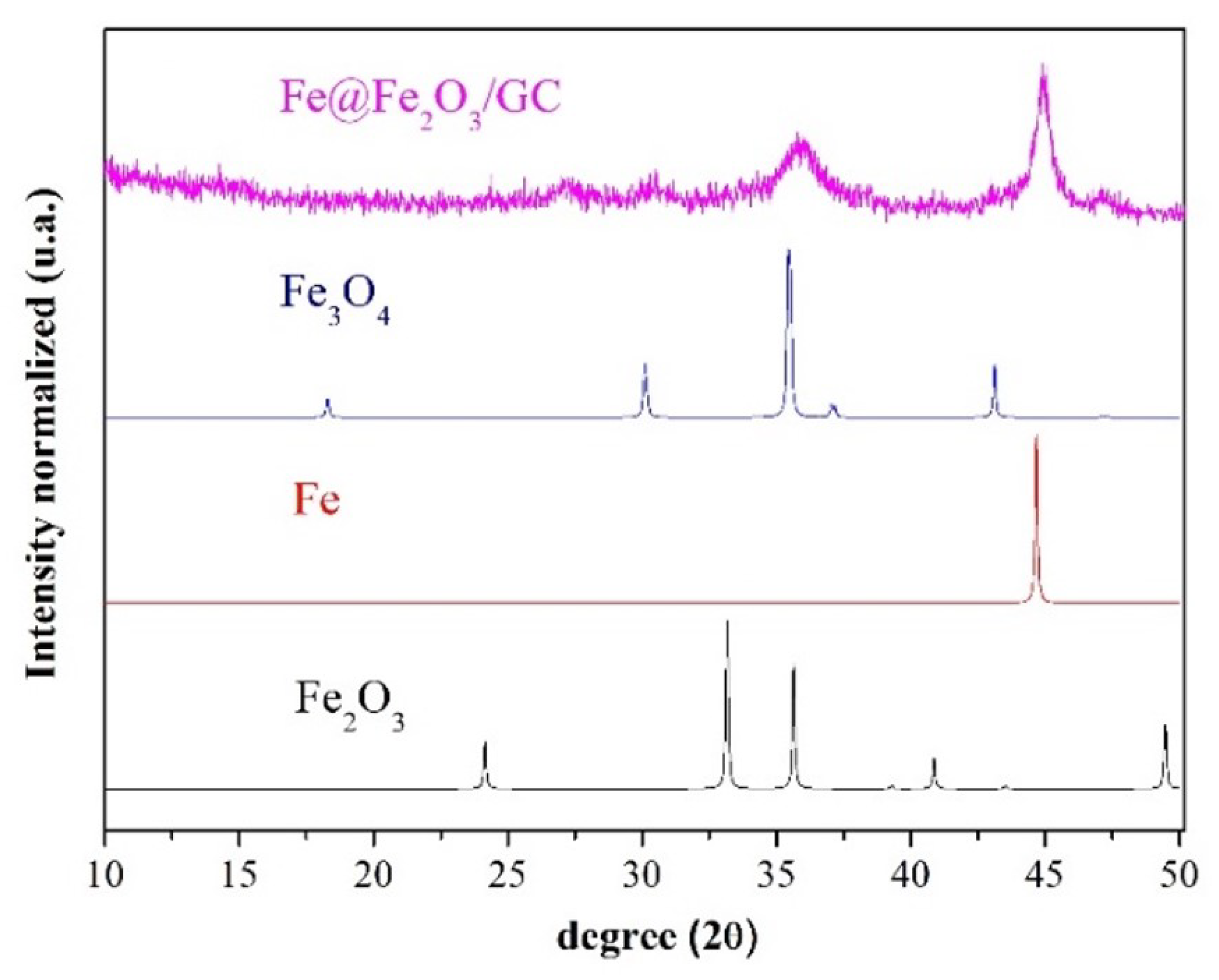
XRD analyses were carried out to characterize the granuled cork used as well as to evaluate the structure of the iron-supported cork after the reduction procedure by using borohydride. Figure 3 shows the diffractogram of pure GC, with the presence of low-intensity peaks at 2θ = 20°, corresponding to the crystalline organic material that is typical of the cork [33], and high-intensity peaks at 37° and 45°, corresponding to calcium and silicon oxides, respectively. In the diffractogram shown in Figure 3, obtained from the modified GC, an intense peak was observed at 2θ = 45°, corresponding to the (110) planes of iron in its zero-valence state. The peaks in the region of 25° to 35° can be attributed to the formation of maghemite (γ-Fe2O3), as well as to magnetite (Fe3O4), respectively. The differences between these results cannot be clearly distinguished due to the amorphous area. In fact, XRF analysis of this sample showed 98.28% iron in its complete composition.
Scanning electron microscopy (SEM) analyses were performed on granulated cork (GC) and Fe@Fe2O3/GC, and the images and elemental mapping of the Fe@Fe2O3/GC catalyst are shown in Figure 4. Morphological characterization revealed that the GC images correspond to the hexagonal/pentagonal prisms observed in the cork microstructure, associated with honeycomb-like or rectangular (brick wall-like) patterns (Figure 4a) [21]. As observed in Figure 4b, Fe@Fe2O3/GC exhibited a collapse of the cork structure, turning into asymmetric sheets with iron oxides supported on their surfaces. It can be observed that the coating is not fixed as a homogeneous, thin layer on the material surface but rather forms deposits inside the macropores, taking advantage of the stacked cell structure. The iron oxide coating distribution formed an irregular surface structure as well as the development of numerous pores, and the iron coating distribution may be uneven between granules, contributing toward heterogeneity in the final material. As observed in Figure 4c,d, EDS elemental mapping further revealed prominent iron, carbon, and oxygen peaks. Carbon and oxygen are present in combination with Fe as can be observed in Figure 4d.
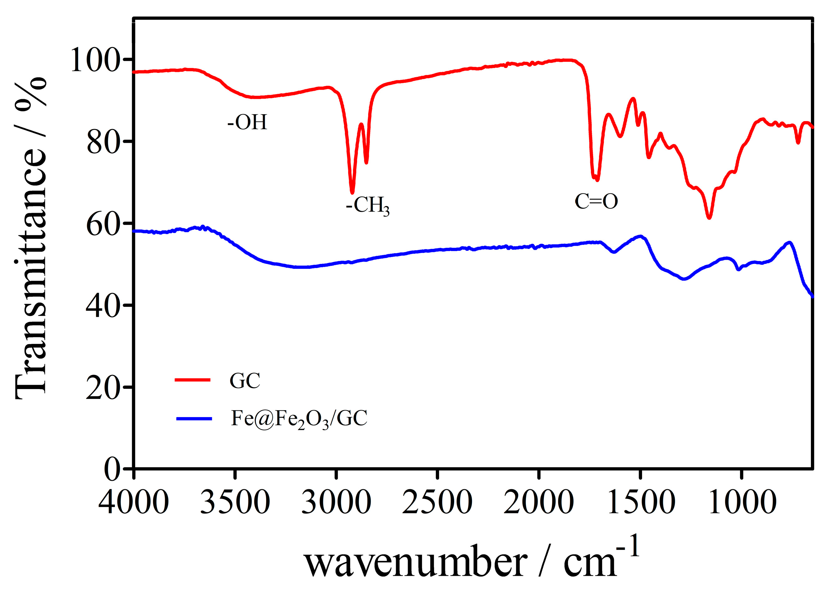
Figure 5 shows the FTIR spectra of GC and Fe@Fe2O3/GC materials, respectively. The band around 3400 cm−1 is related to the elongation and flexing vibrational modes of H–O–H, which is attributed to adsorbed or free water molecules [22]. The double bands at 2928 and 2857 cm−1 are associated with the stretching vibrations of the C–H bonds, typical of -CH2 and -CH3 methyl groups. The 1738, 1274, and 1175 cm−1 bands are attributed to the symmetric and asymmetric stretching vibrations of C=O, respectively, and are typical of aliphatic fatty esters [22,23]. These groups are present in the organic chains that make up cork. The bands at 1627 and 1509 cm−1 correspond to C=C-C stretching vibrations of the aromatic ring [24]. On the other hand, the bands in the region of 2928 and 2857 cm−1 and the band at 1738 cm−1 were not present in the iron-supported cork, while the bands in the region of 1274 and 1175 cm−1 appeared with reduced intensity, indicating the collapse of the structure.

2.3. pH and Conductivity

Figure 6 shows the variation in pH and conductivity conditions with the change in elapsed time for all remediation tests (trials 2–4). At the beginning of the experiment, the pH and conductivity values of the fluid present in the reservoir (tap water) were 7.48 and 249 µS cm−1, respectively. Overall, the pH in all tests firstly increased after 25 h in the cathodic reservoir at 12.5, 11,4 and 12.56 for trials 2, 3, and 4, respectively. Meanwhile, in the anodic reservoir, the pH conditions decreased achieving values of about 1.70, 1.12, and 1.54, respectively. This behavior occurs because of the application of the electric field, which causes electrolysis reactions, and results in the oxidation reaction (anode), generating H+ ions and oxygen gas, and the reduction reaction (cathode), which produces OH ions and hydrogen gas, as shown in Equations (1) and (2) [13,25,26,27].
Anode (oxidation): 2H2O(l) → O2(g) + 4 H+(aq) + 4e E0 = −1.229 V
Cathode (reduction): 4H2O(l) + 4e → 2H2(g) + 4 OH (aq) E0 = −0.828 V
The electrical conductivity (EC) behavior in the anode and cathode reservoirs over seven days of EK remediation is shown in Figure 6. The conductivity of the anodic reservoir is superior to that in the cathodic compartment, in all cases. In all experiments, high conductivity values were obtained when the electroosmotic flux reached its maximum performance (after 25 h).
Figure 7a–d illustrates the pH values in the soil portions after seven days of treatment. As shown, an acidic front was generated in the soil samples in the anodic regions for all tests. Meanwhile, an increase in pH values (3.0–5.5) in the cathodic regions is observed for these same experiments. This behavior is due to the application of the electric field, which generates H+ ions, resulting in a decrease in the pH conditions of the soil near the anode and promoting the formation of an acidic front, which moves towards the cathodic compartment. At the same time, the OH ions raise the pH of the soil near the cathode, generating an alkaline front with an opposite direction to the acidic front [28,29]. Comparing the pH values in trial 2 with those achieved in the other experiments, it is possible to observe that the use of GC-PRB as well as EK/Fe@Fe2O3/GC did not significantly influence the soil pH variations obtained during EK.

2.4. Cumulative EOF

The application of an electric field to the soil results in the transport of water from the anodic to the cathodic reservoir, a process well-known as electroosmosis. The electroosmosis promotes liquid flux that contributes to improve the pollutant removal efficiency, as well as increases the interaction of the soil with the contaminant [14,30,31,32]. For soil contaminated with organic compounds, this is the most significant mechanism for decontamination effects [10], and it is also the main mechanism that determines the kinetics of electrokinetic remediation.
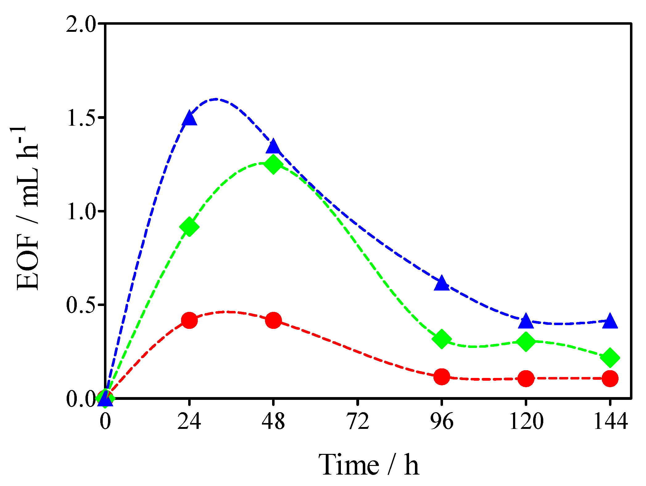
In all experiments, the anodic reservoir volume level decreased during the treatment, while the cathodic reservoir increased its volume level, indicating that EOF occurred from the anodic to the cathodic compartments (Figure 8). When the PRB was introduced in the soil, the EOF rate increased, promoting the migration of contaminants. This phenomenon indicates that the EK/Fe@Fe2O3/GC as a microelectrolysis system can partially increase the zeta potential of the soil close to the PRB and improving the pore-water flow behavior [36,37].

2.5. Distribution of PHE in the Soil after Treatment

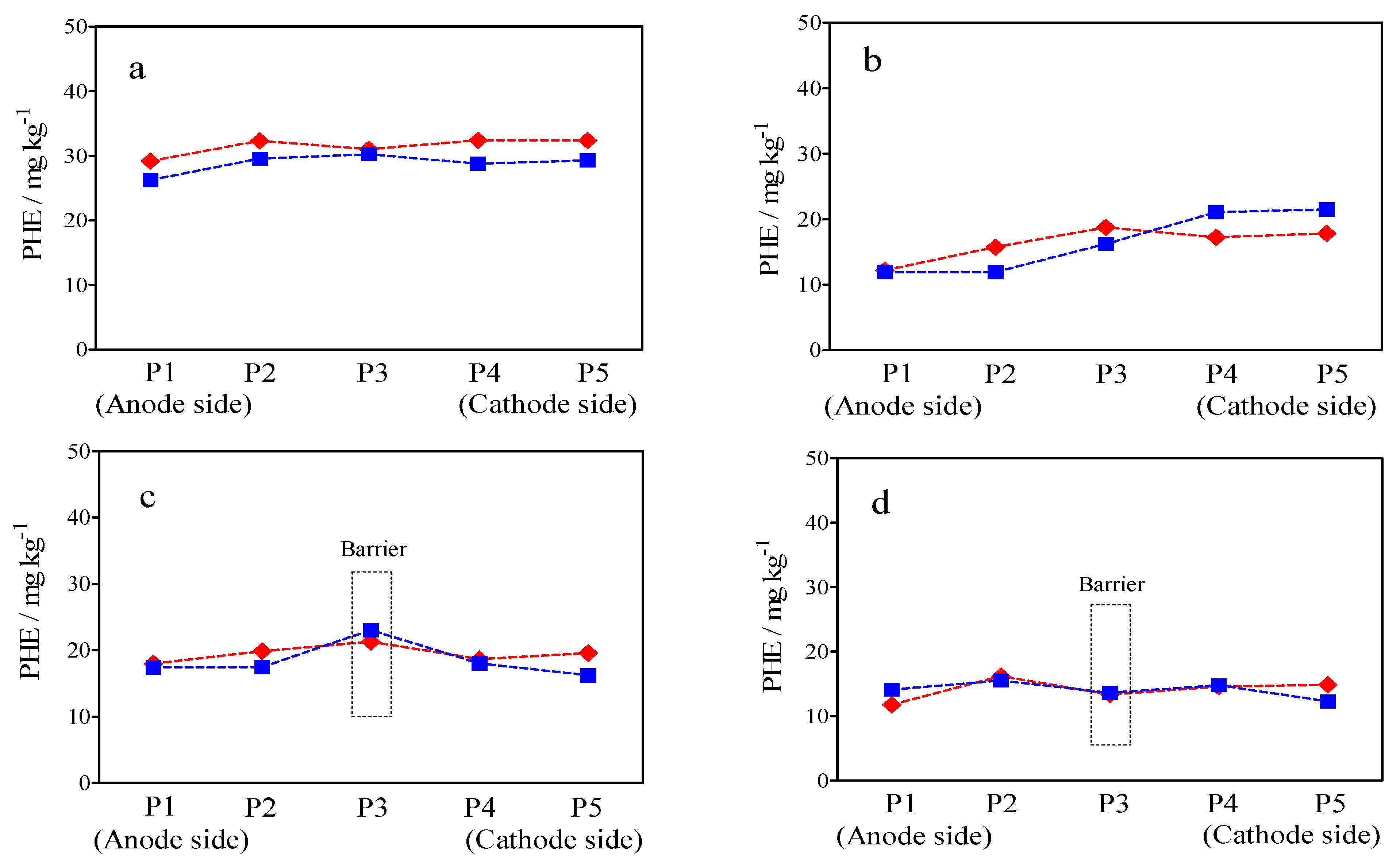
Figure 9 shows the concentrations of PHE distributed in the soil fractions after the EK process. The control experiment without PRB and EK remediation (Trial 1) demonstrated that a limited capability of removing PHE is achieved by evaporation. As shown in Figure 9a, only 10% of the PHE was effectively evaporated. Figure 9b–d show the concentration distribution of the remaining PHE in different sections (P1-P5, as described in Section 3) across the soil treatments (Trials 1–4). In general, in all four tests, the remaining PHE showed an increasing pattern from the anodic to the cathodic reservoir, indicating that the occurrence of electroosmosis is the main transport mechanism removing the target pollutant in the EK process [16]. This behavior was due to the migration of hydrophobic organic matter (PHE) caused by the movement of EOF toward the cathodic reservoir during EK remediation. Soil acidification could simultaneously promote both organic pollutant desorption from soil EOF particles and pollutant migration. The general removal efficiency in all the tests with GC or EK/Fe@Fe2O3/GC was higher than that achieved in Test 1, indicating that the inclusion of EK/Fe@Fe2O3/GC enhanced the migration and removal of PHE in contaminated soil. As shown in Figure 9b, EK remediation removed 40% of the PHE. Instead, the adsorption capacity effect integrated with EK remediation was intensified, achieving approximately 48% (Test 3).
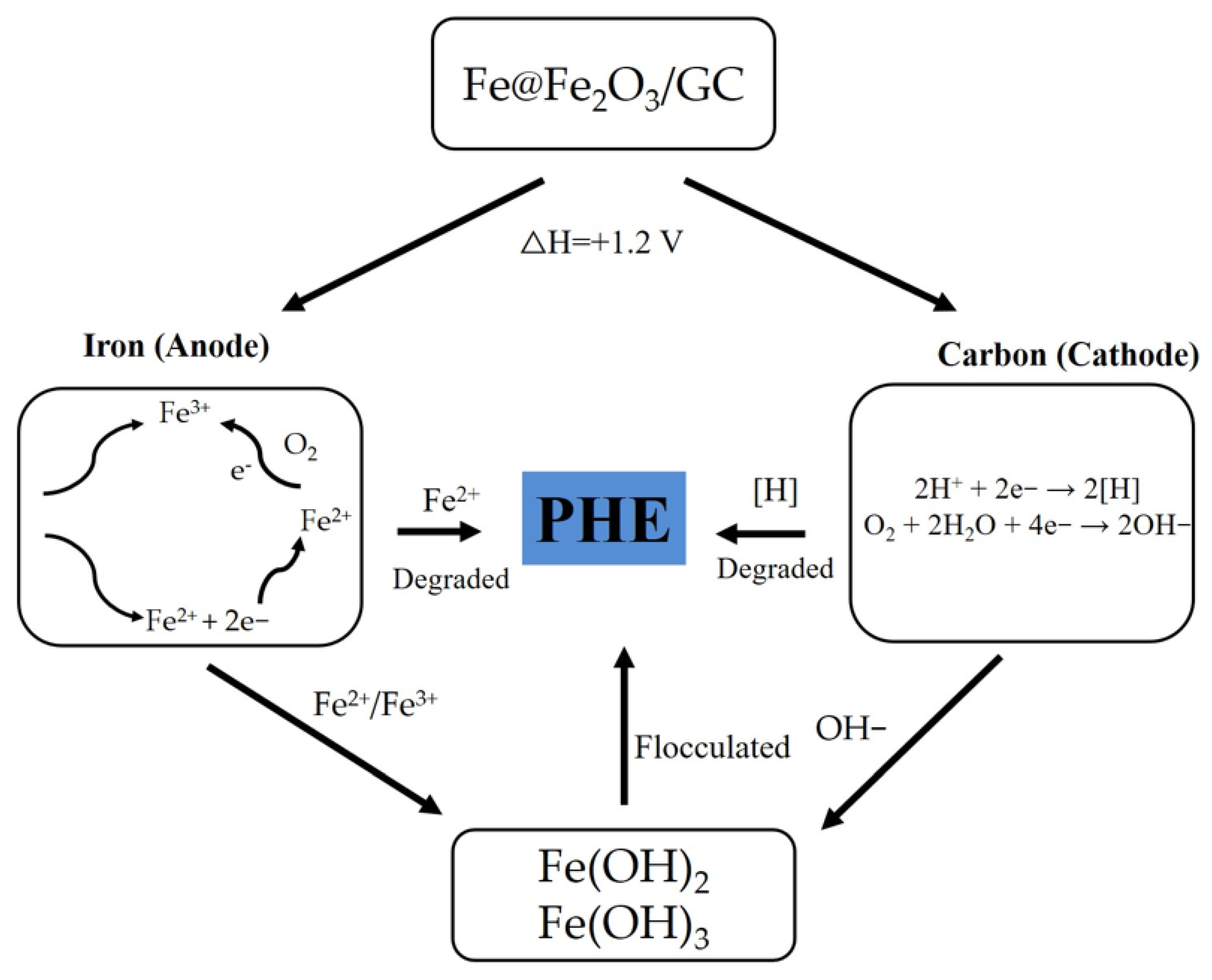
Another important feature that should be indicated is that microelectrolysis is the main mechanism via which Fe@Fe2O3/GC effectively removes and degrades PHE [34]. Fe@Fe2O3/GC microelectrolysis is an integrated process involving oxidation, reduction, flocculation, and adsorption, in which a large number of microscopic galvanic cells are formed, and it is due to the structure of the modified GC catalyst coupled with the current applied. The high efficiency of PHE removal in Trial 4 is attributed to the reduced diffusion of ferrous ions produced by microelectrolysis of the Fe@Fe2O3/GC, into the nearby soil solution, which promoted the desorption and removal of PHE. In the mechanism of Fe@Fe2O3/GC microelectrolysis for PHE degradation, illustrated in Figure 10, microscopic galvanic cells are formed. In these cells, Fe0 acts as an anode and loses 2e to form Fe2+, whereas C acts as a cathode, accelerating the reduction reaction by accepting electrons and transferring the electrons to organic compounds or oxygen [11,34]. The hydrolysis of Fe2+ and Fe3+ ions form ferrous and ferric hydroxides, favoring the flocculants formation to achieve the adsorption and removal of the organic pollutants.

3. Materials

Sodium sulfate anhydrous, ferric chloride, sodium borohydride, iron sulfate, and acetone 99.5% were purchased from Neon Comercial (São Paulo, Brazil) and HPLC grade acetronitrile 99% from JT Baker. GC was purchased from Corksorb (Portugal) and was used as a permeable reactive barrier. Phenanthrene (98%, Sigma-Aldrich, Prague, Czech Republic) was used as the target contaminant. High-purity water was obtained from a Millipore Milli-Q system (Millipore, Bedford, MA, USA) with resistivity >18 MΩ at 25 °C and used to prepare most model solutions.

3.1. Preparation of the Fe@Fe2O3/BC Catalyst

The catalyst was prepared by loading Fe@Fe2O3 on GC by the procedure reported by Li, Ai, and Zhang [37], as follows. A 0.3 g portion of FeCl3·6H2O was dissolved in 100 mL of distilled water, and 0.6 g of NaBH4 was dissolved in 40 mL of distilled water. GC was suspended in in the FeCl3 solution, and after 30 min of sonication of the suspension, the NaBH4 solution was slowly added dropwise to reduce the ferric ions to metallic iron on the GC. The resulting Fe@Fe2O3/GC catalyst was thoroughly washed with deionized water and dried in an oven for further use.

3.2. Characterization of the Fe@Fe2O3/GC Catalyst

The morphological characteristics of the Fe@Fe2O3/GC catalyst were analyzed using scanning electron microscopy (SEM; Carl Zeiss, Auriga, Oberkochen, Germany). The XRD patterns of Fe@Fe2O3/BC and soil were measured using an X-ray powder diffractometer with Cu radiation (Shimadzu, XRD-7000, Kyoto, Japan). X-ray fluorescence spectroscopy (Shimadzu, XRF-1800, Kyoto, Japan) was employed to analyze the surface compositions of Fe@Fe2O3/GC and soil. FTIR spectroscopy images of Fe@Fe2O3/GC and soil were obtained using an infrared spectrometer (Shimadzu, IRAffnity-1, Kyoto, Japan). Energy dispersive spectroscopy was performed using a scanning electron microscope (EDS, Bruker, XFlash detector, Billerica, MA, USA).

3.3. Preparation of Spiked Soil

Kaolinite was selected as a model of low-permeability soil based previous works [14]. Such soil is characterized by inertness, low hydraulic conductivity, lack of organic content, and low cation exchange capacity [35]. The commercial kaolinite used in this study was purchased from Armil Mineração do Nordeste Ltd.a., Brazil. The main physical and chemical properties of the soil were measured according to standard methods and are summarized in Table 2. The soil was then homogeneously polluted with PHE dissolved in acetone, up to a pollution level of approximately 50 mg kg−1 dry soil (this concentration was chosen to simulate an oil spill, based on previous studies). The polluted soil was aerated in a fume hood for one day to ensure evaporation of the acetone, as described in the literature [8,38]. Approximately 200 g of dry soil was used for each test.

3.4. Cell Configuration

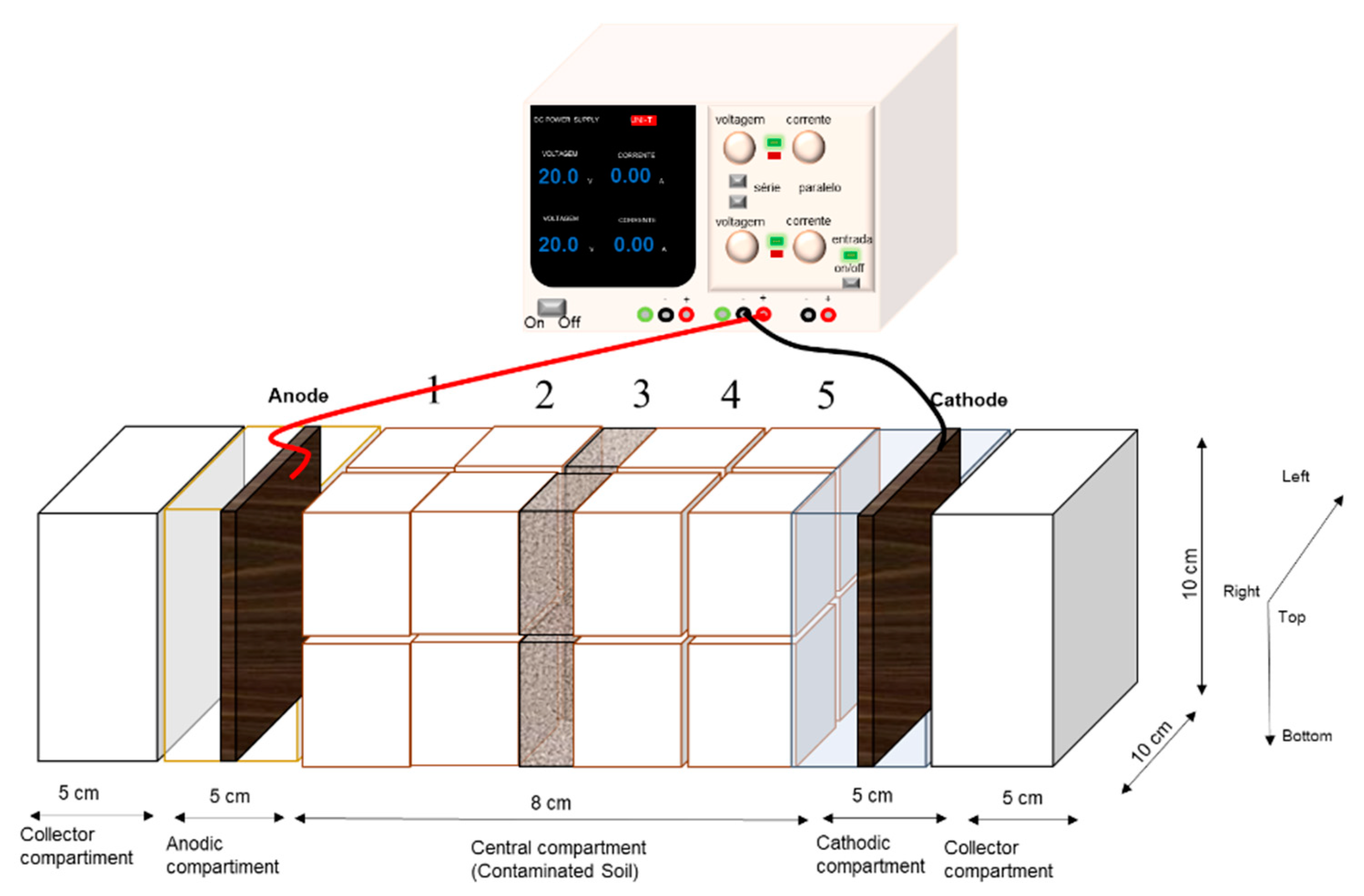
The EK experiments were carried out in a laboratory-scale prototype cell (see Figure 10) mainly composed of: (i) a transparent methacrylate EK cell (8 × 5 × 5 cm); (ii) a constant electric potential of 1 V cm−1 provided by a power supply (MPL-3505 M, Minipa) and applied between the electrodes for seven days; and (iii) two graphite electrodes (5 × 3 × 1 cm), connected to the power supply, so that one worked as a cathode and the other as an anode. The EK cell was divided into five sections: (i) one central compartment, where the polluted-soil, polluted-soil/GC, or polluted-soil/Fe@Fe2O3/GC was loaded; (ii) two electrodic (anodic and cathodic) compartments (5 × 3 × 1 cm), adjacent to the central compartment, in which the graphite electrodes were assembled and tap water (ca. 75 mL) was added; and (iii) two collector compartments, located at the EK cell extremes, into which the EOF overflowed from the electrodic compartments. The anodic/cathodic compartments were separated (i) from the soil-containing section by 0.5 mm nylon meshes and five 13 µm filter papers [25] and (ii) from the collector compartment by an 8.5 cm high methacrylate wall. Five experiments were conducted, as listed in Table 2. The initial water content of the soil was 30% [14,35]. The pH, total organic carbon (TOC), conductivity, and PHE concentration were measured, and after seven days of treatment, the treated soil was divided into 10 portions, and each portion was homogenized and analyzed. The portions P were subdivided and labeled, with P1 nearest the anode and P5 nearest the cathode. In the GC-PRB and Fe@Fe2O3/GC experiments, 1 g of the barrier was inserted in the central portion (P3) of the contaminated soil, as shown in Figure 11.

Analytical Methods

PHE was identified and quantified using high-performance liquid chromatography (HPLC), based on EPA 8310 [39]. To determine the PHE concentration in the soil samples, extraction was carried out based on EPA 3550C [40]. First, 3 g of the contaminated soil was extracted with 25 mL of acetonitrile. The samples were mixed with anhydrous sodium sulfate (3 g) to form a free-flowing powder. They were then extracted with the solvent for 15 min using ultrasonication. The subsequent phase separation was accelerated by the use of an angular centrifuge (Centrifuga Excelsa® II Modelo 206-BL, Fanem) for 4 min at 3000 rpm. A portion of the extract was collected and filtered through 0.45 µm nylon filters (CHROMAFIL® Xtrata, MachereyNagel, Düren, Germany) for HPLC analysis. No extraction was required for the liquid samples. The samples were analyzed by HPLC (Ultimate 3000, Dionex, Sunnyvale, CA, USA) equipped with an autosampler, quaternary gradient pump, and diode-array detector. The analysis was performed using a C18 Acclaim Polar Advantage II column (2 mm × 100 mm, 3 μm, Thermo Fischer Scientific, Waltham, MA, USA) with 10 μL sample injection. The mobile phase consisted of a mixture of deionized water (eluent A) and acetonitrile (eluent B), first using an isocratic elution with A: B = 50:50 v/v for 7 min, followed by a gradual decrease to A: B = 10:90 v/v for 9 min. Finally, the mobile phase was restored to the initial proportions and maintained constant for up to 12 min to balance the column for the next injection. The column and the autosampler were maintained at temperatures of 30 and 5 °C, respectively. The flow rate was 0.350 mL min−1 and the wavelength used for detection was 254 nm. Data were acquired and processed using Chromeleon 6.8 software. The quantification limit was 0.1 mg L−1. The percentage of PHE removal was estimated using Equation (3).
PHE   removal   ( % )   =   PHE 0     PHE final PHE 0   ×   100
Percentage of PHE in soil after treatment for experiments using cork-based PRB and Fe@Fe2O3/GC was estimated taking into account the amount reactive barrier (1 g).
PHE   adsorbed   in   PRB   ( % ) = m 0   m f i n a l m 0   ×   100
where and m0 and mfinal are the total pollutant mass (mg) at the beginning and the end of the test, respectively.
The soil pH and conductivity were measured using the standard EPA 9045C method [40]. This method involves mixing 10 g of soil with 25 mL of distilled water, followed by vortex agitation for 10 min. The humidity measurement was carried out by drying the soil at 105 °C for 24 h.

4. Conclusions

In this study, the performance of EK remediation coupled with PRB of GC and modified CG was investigated for the treatment of soil contaminated with PHE. The main conclusions are as follows:
-
The combination of EK-PRB using GC as a reactive barrier over a period of seven days seems to be an innovative alternative for the treatment of soils polluted with PHE because the contaminants were significantly removed from the samples.
-
The inclusion of PRB in the polluted soil increased the EOF rate, promoting PHE migration, and electroosmosis was the main transport mechanism in the EK process, favoring the elimination of PHE.
-
The use of a reactive barrier formed from GC increased the efficiency of PHE removal by the EK process by 5%, whereas the EK/Fe@Fe2O3/GC process increased the efficiency of this process by 14%, indicating the degradation of PHE by the micro-electrolysis mechanism is feasible and a mechanism was proposed.
-
The modification of GC with Fe@Fe2O3 is not an expensive process that requires a reduced number of steps, avoiding the use of several reagents, which fits the principles of green chemistry well. The alternative use of biomass similarly connects with the goals of circular economy.
Finally, further preparation methods and characterization procedures are being evaluated to demonstrate the efficiency of this modified GC material with Fe@Fe2O3 and these results will be reported in a separate paper.

Author Contributions

Conceptualization, D.R.d.S., C.A.M.-H. and E.V.d.S.; methodology, Á.G.P.G., L.G.A.C. and E.C.T.d.A.C.; formal analysis, Á.G.P.G., L.G.A.C., E.C.T.d.A.C., D.R.d.S., C.A.M.-H. and E.V.d.S.; investigation, Á.G.P.G., L.G.A.C., E.C.T.d.A.C., D.R.d.S., C.A.M.-H. and E.V.d.S.; resources, D.R.d.S., C.A.M.-H. and E.V.d.S.; data curation, Á.G.P.G., L.G.A.C., E.C.T.d.A.C., D.R.d.S., C.A.M.-H. and E.V.d.S.; writing—original draft preparation, Á.G.P.G., L.G.A.C., E.C.T.d.A.C., D.R.d.S., C.A.M.-H. and E.V.d.S.; writing—review and editing, D.R.d.S., C.A.M.-H. and E.V.d.S.; funding acquisition, D.R.d.S., C.A.M.-H. and E.V.d.S. All authors have read and agreed to the published version of the manuscript.

Funding

This research was funded by Conselho Nacional de Desenvolvimento Científico e Tecnológico (Brazil) (CNPq—439344/2018-2, 202095/2019-3, 315879/2021-1), and support from Fundação de Amparo à Pesquisa do Estado de São Paulo (Brazil) with the FAPESP project 2014/50945-4, is gratefully acknowledged. Carlos A. Mar-tínez-Huitle acknowledges the funding provided by the Alexander von Humboldt Foundation (Germany) and CAPES (Brazil) as a Humboldt fellowship for Experienced Researcher (88881.136108/2017-01) at Johannes Gutenberg-Universität Mainz, Germany.

Data Availability Statement

Not applicable.

Acknowledgments

Financial support from Conselho Nacional de Desenvolvimento Científico e Tecnológico (Brazil) (CNPq—439344/2018-2, 202095/2019-3, 315879/2021-1), and support from Fundação de Amparo à Pesquisa do Estado de São Paulo (Brazil) with the FAPESP project 2014/50945-4, is gratefully acknowledged. Carlos A. Martínez-Huitle acknowledges the funding provided by the Alexander von Humboldt Foundation (Germany) and CAPES (Brazil) as a Humboldt fellowship for Experienced Researcher (88881.136108/2017-01) at Johannes Gutenberg-Universität Mainz, Germany. The authors thank the Núcleo de Processamento Primário e Reúso de Água Produzida e Resíduos (NUPPRAR) for providing HPLC analyses.

Conflicts of Interest

The authors declare no conflict of interest.

References

  1. Mouronte, N.; Álvarez, M.S.; Deive, F.J.; Rodríguez, A. Combining Biodegradable Surfactants and Potassium Inorganic Salts for Efficiently Removing Polycyclic Aromatic Hydrocarbons from Aqueous Effluents. J. Water Process Eng. 2022, 47, 102796. [Google Scholar] [CrossRef]
  2. Chu, L.; Cang, L.; Sun, Z.; Wang, X.; Fang, G.; Gao, J. Reagent-Free Electrokinetic Remediation Coupled with Anode Oxidation for the Treatment of Phenanthrene Polluted Soil. J. Hazard Mater. 2022, 433, 128724. [Google Scholar] [CrossRef] [PubMed]
  3. Park, J.Y.; Lee, H.H.; Kim, S.J.; Lee, Y.J.; Yang, J.W. Surfactant-Enhanced Electrokinetic Removal of Phenanthrene from Kaolinite. J. Hazard Mater. 2007, 140, 230–236. [Google Scholar] [CrossRef]
  4. de Oliveira Silva, K.N.; Rodrigo, M.A.; dos Santos, E.V. Electrochemical Treatment of Soil-Washing Effluent with Boron-Doped Diamond Electrodes: A Review. Curr. Opin. Solid State Mater. Sci. 2021, 25, 100962. [Google Scholar] [CrossRef]
  5. Araujo, K.C.; Silva, K.N.; da Silva, D.R.; Quiroz, M.A.; Martinez-Huitle, C.A.; Santos, E.V. The Green Use of Persulfate Electrochemically Generated with Diamond Electrodes for Depolluting Soils. In Proceedings of the 240th ECS Meeting: Symposium: L05: Electrochemical Water Remediation, Orlando, FL, USA, 10–14 October 2021; p. #L05-1530. [Google Scholar]
  6. Befkadu, A.A.; Chen, Q. Surfactant-Enhanced Soil Washing for Removal of Petroleum Hydrocarbons from Contaminated Soils: A Review. Pedosphere 2018, 28, 383–410. [Google Scholar] [CrossRef]
  7. Mena, E.; Villaseñor, J.; Rodrigo, M.A.; Cañizares, P. Electrokinetic Remediation of Soil Polluted with Insoluble Organics Using Biological Permeable Reactive Barriers: Effect of Periodic Polarity Reversal and Voltage Gradient. Chem. Eng. J. 2016, 299, 30–36. [Google Scholar] [CrossRef]
  8. Mena, E.; Ruiz, C.; Villaseñor, J.; Rodrigo, M.A.; Cañizares, P. Biological Permeable Reactive Barriers Coupled with Electrokinetic Soil Flushing for the Treatment of Diesel-Polluted Clay Soil. J. Hazard Mater. 2015, 283, 131–139. [Google Scholar] [CrossRef] [PubMed] [Green Version]
  9. Huguenot, D.; Mousset, E.; van Hullebusch, E.D.; Oturan, M.A. Combination of Surfactant Enhanced Soil Washing and Electro-Fenton Process for the Treatment of Soils Contaminated by Petroleum Hydrocarbons. J. Environ. Manag. 2015, 153, 40–47. [Google Scholar] [CrossRef]
  10. Ng, Y.S.; sen Gupta, B.; Hashim, M.A. Stability and Performance Enhancements of Electrokinetic-Fenton Soil Remediation. Rev. Environ. Sci. Biotechnol. 2014, 13, 251–263. [Google Scholar] [CrossRef]
  11. Andrade, D.C.; dos Santos, E.V. Combination of Electrokinetic Remediation with Permeable Reactive Barriers to Remove Organic Compounds from Soils. Curr. Opin. Electrochem. 2020, 22, 136–144. [Google Scholar] [CrossRef]
  12. Rodrigo, M.A.; dos Santos, E.V. Electrochemically Assisted Remediation of Contaminated Soils; Rodrigo, M.A., Vieira dos Santos, E., Eds.; Springer: Berlin/Heidelberg, Germany, 2020; ISBN 9783030681395. [Google Scholar]
  13. Rodrigo, M.A.; Oturan, M.A.; Oturan, N. Electrochemically Assisted Remediation of Pesticides in Soils and Water: A Review. Chem. Rev. 2014, 114, 8720–8745. [Google Scholar] [CrossRef] [PubMed]
  14. Paixão, I.C.; López-Vizcaíno, R.; Solano, A.M.S.; Martínez-Huitle, C.A.; Navarro, V.; Rodrigo, M.A.; dos Santos, E.V. Electrokinetic-Fenton for the Remediation Low Hydraulic Conductivity Soil Contaminated with Petroleum. Chemosphere 2020, 248, 126029. [Google Scholar] [CrossRef] [PubMed]
  15. Pazos, M.; Rosales, E.; Alcántara, T.; Gómez, J.; Sanromán, M.A. Decontamination of Soils Containing PAHs by Electroremediation: A Review. J. Hazard Mater. 2010, 177, 1–11. [Google Scholar] [CrossRef] [PubMed]
  16. Fdez-Sanromán, A.; Pazos, M.; Rosales, E.; Sanromán, M.Á. Prospects on Integrated Electrokinetic Systems for Decontamination of Soil Polluted with Organic Contaminants. Curr. Opin. Electrochem. 2021, 27, 100692. [Google Scholar] [CrossRef]
  17. Andrade, D.C.; Đolić, M.B.; Martínez-Huitle, C.A.; dos Santos, E.V.; Silva, T.F.; Vilar, V.J. Coupling Electrokinetic with a Cork-Based Permeable Reactive Barrier to Prevent Groundwater Pollution: A Case Study on Hexavalent Chromium- Contaminated Soil. Electrochim. Acta 2022, 429, 140936. [Google Scholar] [CrossRef]
  18. Vieira dos Santos, E.; Sáez, C.; Cañizares, P.; Martínez-Huitle, C.A.; Rodrigo, M.A. Reversible Electrokinetic Adsorption Barriers for the Removal of Atrazine and Oxyfluorfen from Spiked Soils. J. Hazard Mater. 2017, 322, 413–420. [Google Scholar] [CrossRef]
  19. Mena, E.; Villaseñor, J.; Cañizares, P.; Rodrigo, M.A. Influence of Electric Field on the Remediation of Polluted Soil Using a Biobarrier Assisted Electro-Bioremediation Process. Electrochim. Acta 2016, 190, 294–304. [Google Scholar] [CrossRef] [Green Version]
  20. Pintor, A.M.A.; Vieira, B.R.C.; Boaventura, R.A.R.; Botelho, C.M.S. Removal of Antimony from Water by Iron-Coated Cork Granulates. Sep. Purif. Technol. 2020, 233, 116020. [Google Scholar] [CrossRef]
  21. Amalero, E.G.; Ingua, G.L.; Erta, G.B.; Emanceau, P.L. Review Article Methods for Studying Root Colonization by Introduced. Agronomie 2003, 23, 407–418. [Google Scholar] [CrossRef] [Green Version]
  22. Wang, Q.; Lai, Z.; Mu, J.; Chu, D.; Zang, X. Converting Industrial Waste Cork to Biochar as Cu (II) Adsorbent via Slow Pyrolysis. Waste Manag. 2020, 105, 102–109. [Google Scholar] [CrossRef]
  23. Abenojar, J.; López de Armentia, S.; Barbosa, A.Q.; Martínez, M.A.; Velasco, F.; da Silva, L.F.M.; del Real Romero, J.C. Coating Cork Particles with Iron Oxide: Effect on Magnetic Properties. Wood Sci. Technol. 2020, 54, 869–889. [Google Scholar] [CrossRef]
  24. Miranda, I.; Gominho, J.; Pereira, H. Cellular Structure and Chemical Composition of Cork from the Chinese Cork Oak (Quercus Variabilis). J. Wood Sci. 2013, 59, 1–9. [Google Scholar] [CrossRef]
  25. Şen, A.; Marques, A.V.; Gominho, J.; Pereira, H. Study of Thermochemical Treatments of Cork in the 150–400 °C Range Using Colour Analysis and FTIR Spectroscopy. Ind. Crops Prod. 2012, 38, 132–138. [Google Scholar] [CrossRef]
  26. De Paiva, S.D.S.M.; da Silva, I.B.; de M. Santos, E.C.M.; Rocha, I.M.V.; Martínez-Huitle, C.A.; dos Santos, E.V. Coupled Electrochemical Processes for Removing Dye from Soil and Water. J. Electrochem. Soc. 2018, 165, E318–E324. [Google Scholar] [CrossRef]
  27. Silva, K.N.O.; Paiva, S.S.M.; Souza, F.L.; Silva, D.R.; Martínez-Huitle, C.A.; Santos, E.V. Applicability of Electrochemical Technologies for Removing and Monitoring Pb2+ from Soil and Water. J. Electroanal. Chem. 2018, 816, 171–178. [Google Scholar] [CrossRef]
  28. de Melo Henrique, J.M.; Isidro, J.; Saez, C.; Dos Santos, E.V.; Rodrigo, M.A. Removal of Lindane Using Electrokinetic Soil Flushing Coupled with Air Stripping. J. Appl. Electrochem. 2022, 52, 1317–1326. [Google Scholar] [CrossRef]
  29. López-Vizcaíno, R.; Sáez, C.; Cañizares, P.; Navarro, V.; Rodrigo, M.A. Influence of the Type of Surfactant on the Mobility of Flushing Fluids for Electro-Remediation Processes. Sep. Sci. Technol. 2011, 46, 2148–2156. [Google Scholar] [CrossRef]
  30. Dos Santos, E.V.; Medeiros, M.O.; Dos Anjos, A.D.; Martínez-Huitle, C.A.; Da Silva, D.R. Application of Electrochemical Technologies to Treat Polluted Soil by Diesel. Chem. Eng. Trans. 2014, 41, 157–162. [Google Scholar] [CrossRef]
  31. Reddy, K.R.; Urbanek, A.; Khodadoust, A.P. Electroosmotic Dewatering of Dredged Sediments: Bench-Scale Investigation. J. Environ. Manag. 2006, 78, 200–208. [Google Scholar] [CrossRef]
  32. López Vizcaíno, R.; Yustres, A.; Asensio, L.; Saez, C.; Cañizares, P.; Rodrigo, M.A.; Navarro, V. Enhanced Electrokinetic Remediation of Polluted Soils by Anolyte PH Conditioning. Chemosphere 2018, 199, 477–485. [Google Scholar] [CrossRef]
  33. López-Vizcaíno, R.; dos Santos, E.V.; Yustres, A.; Rodrigo, M.A.; Navarro, V.; Martínez-Huitle, C.A. Calcite Buffer Effects in Electrokinetic Remediation of Clopyralid-Polluted Soils. Sep. Purif. Technol. 2019, 212, 376–387. [Google Scholar] [CrossRef]
  34. Ren, D.; Li, S.; Wu, J.; Fu, L.; Zhang, X.; Zhang, S. Remediation of Phenanthrene-Contaminated Soil by Electrokinetics Coupled with Iron/Carbon Permeable Reactive Barrier. Environ. Eng. Sci. 2019, 36, 1224–1235. [Google Scholar] [CrossRef]
  35. López-Vizcaíno, R.; Alonso, J.; Cañizares, P.; León, M.J.; Navarro, V.; Rodrigo, M.A.; Sáez, C. Removal of Phenanthrene from Synthetic Kaolin Soils by Eletrokinetic Soil Flushing. Sep. Purif. Technol. 2014, 132, 33–40. [Google Scholar] [CrossRef]
  36. Sun, Y.; Gao, K.; Zhang, Y.; Zou, H. Remediation of Persistent Organic Pollutant-Contaminated Soil Using Biosurfactant-Enhanced Electrokinetics Coupled with a Zero-Valent Iron/Activated Carbon Permeable Reactive Barrier. Environ. Sci. Pollut. Res. 2017, 24, 28142–28151. [Google Scholar] [CrossRef] [PubMed]
  37. Li, J.; Ai, Z.; Zhang, L. Design of a Neutral Electro-Fenton System with Fe@Fe2O3/ACF Composite Cathode for Wastewater Treatment. J. Hazard Mater. 2009, 164, 18–25. [Google Scholar] [CrossRef] [PubMed]
  38. López-Vizcaíno, R.; Sáez, C.; Cañizares, P.; Rodrigo, M.A. The Use of a Combined Process of Surfactant-Aided Soil Washing and Coagulation for PAH-Contaminated Soils Treatment. Sep. Purif. Technol. 2012, 88, 46–51. [Google Scholar] [CrossRef]
  39. Choe, J.-H. Polynuclear Aromatic Hydrocarbons. Clim. Chang. 1986, 9, 123–128. [Google Scholar]
  40. Agency Environmental Protection, SW-846 Test Method 3546: Microwave Extraction, Hazard. Waste Test Methods/SW-846. 2007, 1–13. Available online: https://www.epa.gov/hw-sw846/sw-846-test-method-3546-microwave-extraction (accessed on 17 September 2022).
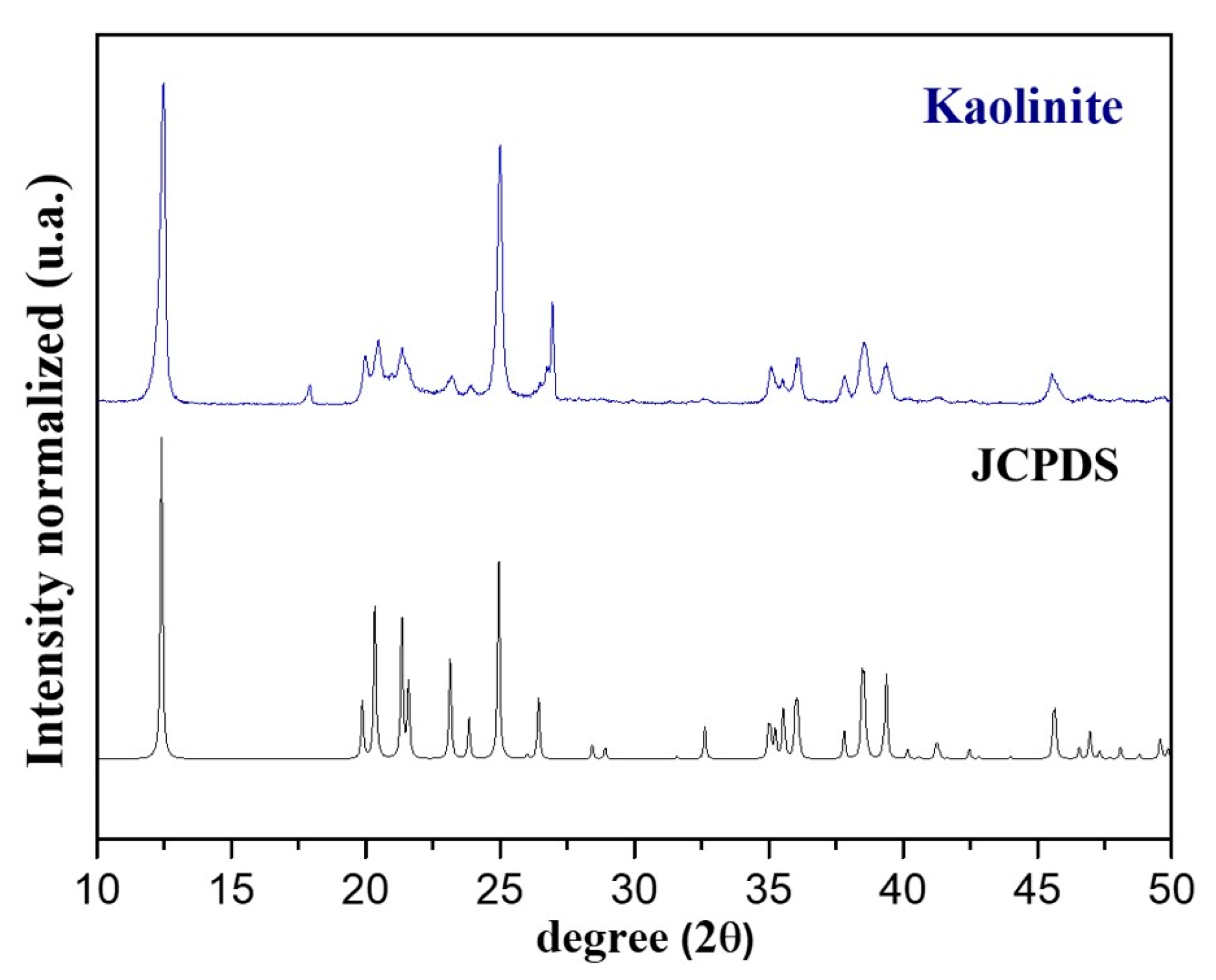
Figure 1. Characterization of kaolinite by XRD analysis.
Catalysts 12 01591 g001
Figure 2. FTIR spectrum of the kaolinite-based clay soil sample.
Catalysts 12 01591 g002
Figure 3. XRD pattern of the Fe@Fe2O3/GC.
Catalysts 12 01591 g003
Figure 4. SEM images of (a) GC, (b) Fe@Fe2O3/GC, (c,d) EDS spectra and elemental mapping of the as-fabricated Fe@Fe2O3/GC.
Catalysts 12 01591 g004
Figure 5. FTIR spectra of GC and Fe@Fe2O3/GC.
Catalysts 12 01591 g005
Figure 6. Time course of observed changes in pH (full symbol) and conductivity conditions (empty symbol): (●○) anode and (▲△) cathode. (a) EK without PRB, (b) EK with GC-PRB and (c) EK/Fe@Fe2O3/GC.
Catalysts 12 01591 g006
Figure 7. Time course of the pH and conductivity profiles in the electrolyte wells for an electric field of 1 V cm−1, after a 7-day remediation test: (a) without EK and PRB, (b) EK without PRB, (c) EK with GC-PRB, and (d) EK/Fe@Fe2O3/GC treatment.
Catalysts 12 01591 g007
Figure 8. Time course of the EOF profiles in the electrolyte wells for an electric field of 1 V cm−1, after the 7-day remediation test: (●) EK without PRB, (♦) EK with GC-PRB, and (▲) EK/Fe@Fe2O3/GC.
Catalysts 12 01591 g008
Figure 9. Concentration distribution of PHE across soil column in tests performed by applying an electric field of 1 V cm−1, after seven days of remediation: (a) without EK and PRB, (b) EK without PRB, (c) EK with GC-PRB, and (d) EK/Fe@Fe2O3/GC. (■) Bottom and (♦) Top.
Catalysts 12 01591 g009
Figure 10. Mechanism of Fe@Fe2O3/GC microelectrolysis for degradation of PHE.
Catalysts 12 01591 g010
Figure 11. Experimental setup used to study the EK process sampling point for postmortem analysis.
Catalysts 12 01591 g011
Table 1. Properties of kaolinite.
Chemical Composition
SiO263.06
Al2O335.60
Fe2O30.76
K2O0.56
MgO0.02
Mineralogical composition
Kaolinite (%)95
Quartz5
pH4.8
Conductivity (µS cm−1)470
PHE/mg kg−150
Table 2. Main operating conditions for each PHE-contaminated soil remediation trial.
TrialSupporting Electrolyte/ReservoirElectric Field (V cm−1)Time (Days)
#AnodicCathodic
1Without EK and PRB---7
2EK without PRBTap waterTap water17
3EK with GC-PRBTap waterTap water17
4EK/Fe@Fe2O3/GCTap waterTap water17
Publisher’s Note: MDPI stays neutral with regard to jurisdictional claims in published maps and institutional affiliations.