Article

Effect of the Ni/Al Ratio on the Performance of NiAl2O4 Spinel-Based Catalysts for Supercritical Methylcyclohexane Catalytic Cracking

1
Department of Chemical and Biological Engineering, Korea University, 145 Anam-ro, Seoul 02841, Korea
2
Carbon Conversion Research Laboratory, Korea Institute of Energy Research, 152 Gajeong-ro, Yuseong-gu, Daejeon 34129, Korea
3
Agency for Defense Development, Jochiwongil 462, Yuseong-gu, Daejeon 34186, Korea
*
Author to whom correspondence should be addressed.
Catalysts 2021, 11(3), 323; https://doi.org/10.3390/catal11030323
Submission received: 10 February 2021 / Revised: 24 February 2021 / Accepted: 26 February 2021 / Published: 2 March 2021
(This article belongs to the Special Issue Nickel-Based Catalysts for Hydrocarbon Fuel Reforming)

Abstract

:
Supercritical methylcyclohexane cracking of NiAl2O4 spinel-based catalysts with varying Ni/Al deficiencies was investigated. Thus, catalysts with Ni content of 10–50 wt.% were prepared by typical co-precipitation methods. The calcined, reduced, and spent catalysts were characterized by X-ray diffraction, O2 temperature-programmed oxidation, NH3 temperature-programmed desorption, N2 physisorption, O2 chemisorption, scanning and transmission electron microscopy, and X-ray fluorescence. The performance and physicochemical properties of the reference stoichiometric Ni3Al7 catalyst differed significantly from those of the other catalysts. Indeed, the Ni-deficient Ni1Al9 catalyst led to the formation of large Ni particles (diameter: 20 nm) and abundant strong acid sites, without spinel structure formation, owing to the excess Al. These acted with sufficient environment and structure to form the coke precursor nickel carbide, resulting in a pressure drop within 17 min. On the other hand, the additional NiO linked to the NiAl2O4 spinel structure of the Al-deficient Ni5Al5 catalyst formed small crystals (10 nm), owing to the excess Ni, and displayed improved Ni dispersion. Thus, dehydrogenation proceeded effectively, thereby improving the resistance to coke formation. This catalytic behavior further demonstrated the remarkable activity and stability of this catalyst under mild conditions (450 °C and 4 Mpa).

Graphical Abstract

1. Introduction

Recently, the development of hypersonic vehicles has attracted significant attention in the field of defense science and technology and the development of next-generation commercial airplanes. The management of aerodynamic frictional heat under hypersonic flight conditions has been recognized as one of the main technical obstacles facing commercialization. Among the technologies proposed for heat management, the heat absorption cooling system using the physical sensible heat and chemical heat sink from the endothermic cracking reaction of on-board liquid fuel has proved the most promising [1,2,3].
Because hypersonic vehicles are operated within Mach 5–10, the internal conditions of the combustion chamber tend to change to supercritical, owing to the compressed air at such flight speeds. Conventional aviation fuels such as Jet A-1 are reported to be thermally unstable under supercritical conditions, leading to technical problems in the fuel supply system. Hence, specialized jet fuel is under development to secure thermal stability at hypersonic supercritical conditions. Generally, cyclic hydrocarbons such as methylcyclohexane (MCH) and decalin are well-known additives that enhance the thermal stability of jet fuel. However, relatively thermally stable cyclic hydrocarbons are likely to be less reactive and proceed to different reaction pathways during catalytic endothermic cracking [4,5,6].
Kim et al. [7] studied the catalytic cracking of MCH in a batch-type reactor at 5 MPa and 325 °C using various zeolites (HZSM-5, beta zeolite, and HY zeolite) and reported the correlation of the product selectivity with the total acid density measured by NH3 temperature-programmed desorption (NH3-TPD). In particular, HZSM-5 showed the highest heat sink properties with increased product selectivity toward gaseous hydrogen and light olefins, owing to its adequate total acid density and pore structure. However, SiO2–Al2O3-based catalysts easily induce coke formation due to their excessive acid sites [8,9]. In addition, it is difficult to control the selectivity of the product because of the irregular reaction path of the acid catalyst, which proceeds via the carbenium ion mechanism [10]. Generally, the high selectivity of H2 and light olefins has been reported as a way to increase the heat sink and fuel combustion efficiencies [3]. Thus, noble metal catalysts undergoing dehydrogenation have been studied as alternative hydrocarbon cracking catalysts. [11,12]. Nixon et al. [13] demonstrated for the first time that selective dehydrogenation of MCH by Pt/Al2O3 catalysts can provide a heat sink of approximately 2100 kJ/kg, proving that it would satisfy the heat sink sufficiently for cooling to Mach 4–6. Indeed, the group 10 noble metals Pt and Pd are easy to dehydrogenate because of their excellent hydrogen transfer ability; however, their high cost limits their application.
As described above, the properties of the catalysts used in this process greatly influence MCH conversion and product selectivity. In particular, to improve the catalyst activity, it is necessary to promote C–C and C–H bond rupture while preserving the metal and acid sites from carbon deposition. To date, this field has mainly focused on acid catalysts and catalysts based on noble metals (Pt, Pd). On the other hand, the group 10 non-noble metal Ni has the advantages of availability, low cost, and excellent ability to break C–C and C–H bonds [14,15]; however, few studies on MCH supercritical catalytic cracking using Ni-based catalysts, have been reported to date.
The NiAl2O4 spinel structure is well known as one of the structures that efficiently disperse Ni [16,17,18,19,20]. In particular, this structure has been reported to be excellent in stability against carbon deposition in the reforming reaction [16,17]. It is known that the carbon saturation concentration appears higher at a higher surface/volume ratio of Ni particles [21,22]. Thus, smaller Ni particles have a higher strength against carbon deposition due to the carbon diffusion of less driving force. Additionally, Al2O3 has Lewis acid properties [23]. The NiAl2O4 spinel structure consists of metallic Ni species dispersed on an Al2O3 support after reduction. As described above, the Lewis acid site acts as an active site for hydrocarbon fuel catalytic cracking. Therefore, it is suggested that the combination of the two transition metals can cause a synergistic effect.
With this in mind, in this study, we investigated the catalytic cracking of MCH using Ni-based catalysts, at a relatively low temperature of 450 °C, to minimize coke formation and prevent sintering of the active metal. The structural properties of the co-precipitated Ni–Al precursors were characterized by X-ray diffraction (XRD), N2 physisorption, O2 chemisorption, and scanning (SEM) and transmission (TEM) electron microscopy and correlated with the size and dispersion of the formed Ni particles. Moreover, the acid properties were measured by NH3-TPD. Finally, the catalytic performance and reaction pathways were elucidated based on the experimental results.

2. Results and Discussion

2.1. Catalyst Characterization

2.1.1. XRD Analysis

To closely investigate the structural properties of the prepared NiAl2O4 catalysts, the XRD patterns were phase-matched for the chemical composition of the aggregate using Jade 6.5 software.
Figure 1 illustrates the XRD results of the NiAl2O4 catalysts with different Ni contents before (Figure 1a) and after (Figure 1b) reduction at 700 °C. In both sets of results, notably different diffraction peaks were observed at 2θ values between 40° and 50°. As shown in Figure 1a, the Ni3Al7 pattern was consistent with that of the face-centered cubic structure of nickel aluminate (space group: Fd-3m) assigned to the NiAl2O4 spinel (JCPDS 78-1601). Peaks were observed at 2θ values of 19.6°, 31.7°, 37.5°, 45.3°, 60.2°, and 66.1°, which were, respectively, assigned to the (111), (220), (311), (400), (511), and (440) diffraction planes of the NiAl2O4 spinel structure [24,25,26]. With the increase in Al content, the peak at 2θ = 45.3° shifted to a higher value (45.8°) and the Al2O3 peak was observed as the main peak. As a result, Ni1Al9 hindered the oxidation of Ni by excess Al, leading to the sole formation of Al2O3 without any NiAl2O4 spinel formation. With the increase in the Ni content, the resultant peaks were broader than those of Ni3Al7, with the peaks at 45.3°, corresponding to the (400) plane of NiAl2O4, shifting to 44.7°. Following the formation of the NiAl2O4 spinel, the excess Ni was converted to NiO, resulting in shoulder signals at 43.5° and 63.2° (JCPDS 78-0643). The mechanism of spinel NiAl2O4 formation reportedly comprises the solid reaction between both NiO and Al2O3 via the thermal diffusion of the cation metals through the early-formed aluminate [27,28]. In this mechanism, decomposition into 2Al3+ and oxygen gas occurs by thermal diffusion of the Ni2+ ions at the Al2O3 interface to form a spinel of 2NiAl2O4 (Equation (1)). Furthermore, the precursor oxygen or that produced by the decomposition of Al2O3 (Equation (1)) is supplied to the NiO interface through the reaction area and reacts with the aluminum ions to form a spinel of NiAl2O4 (Equation (2)):
At the Al2O3 interface:
3Al2O3 + 2Ni2+ → 2NiAl2O4 +2Al3+ + 0.5 O2
At the NiO interface:
3NiO + 2Al3+ + 0.5 O2 → NiAl2O4 + 2Ni2+
Overall, the Ni1Al9 catalyst containing excess Al without the formation of a NiAl2O4 spinel led to the formation of relatively large particles (mean diameter: 20.8 nm) as a result of the irregularly arranged Ni during reduction. On the other hand, the formed Ni3Al7 and Ni5Al5 catalysts suppressed Ni sintering, owing to the regular arrangement of Ni in the spinel structure; therefore, Ni3Al7 and Ni5Al5 formed smaller particles (diameter: 9–10 nm). These results well agreed with the TEM and O2 chemisorption results (Table 1).

2.1.2. SEM Analysis

Figure 2 shows the scanning electron micrographs before and after the reduction of the NiAl2O4 catalysts with various Ni/Al ratios. Overall, the nanoparticles in all the catalysts were well-aggregated. After calcination, Ni1Al9 displayed a spherical morphology (Figure 2a) which gradually changed into a rod morphology with increasing Ni content. This change in morphology indicates that an increase in NiAl2O4 spinel structure formation can be attained by meeting the stoichiometric ratio. The SEM image of the Ni5Al5 catalyst is of great interest. The XRD results revealed the coexistence of NiO and spinel NiAl2O4 in Ni5Al5; however, the largest number of formed rod particles comprised the latter. These results show that the NiAl2O4 spinel structure is linked to the NiO particles and thus prevents aggregation and growth of these particles [29]. Therefore, we supposed that the NiO particles attach as small particles to the NiAl2O4 spinel structure without growing into a large crystal, thereby maintaining the rod shape of the spinel structure. Additionally, this spinel structure in the reduced catalyst changed to a snowflake morphology, suggesting that it was formed by the removal of oxygen (Figure 2). The distribution of this structure also increased with increasing Ni content as was observed in the reduction process.

2.1.3. TEM Analysis

Figure 3 shows the transmission electron micrographs and Ni particle size distribution histograms of the reduced NiAl2O4 catalyst with various Ni contents. The mean Ni particle sizes were assessed from an accumulated frequency of up to 95% of the entire occupants and are listed in Table 1. Moreover, the Ni crystal sizes calculated by the Scherrer equation using information on the (111) planes obtained from the XRD results and the O2 chemisorption proposed by Milleta et al. [30] are listed in Table 1.
Spherically shaped Ni particles were observed in all the reduced NiAl2O4 catalysts. The XRD and O2 chemisorption measurements well agreed with the TEM results within the same error range. Thus, Ni1Al9 was observed as the largest particle (diameter: ˃20 nm), despite having a nickel content of 10%. As described above in the XRD analysis section (Section 2.1.1), this is explained by the sintering of Ni, which is easily caused by the irregular arrangement of Ni in the absence of a NiAl2O4 spinel structure. Conversely, Ni3Al7, with the most optimal ratio in the NiAl2O4 spinel structure, displayed the smallest particle sizes (diameter: 9–10 nm). Ni5Al5 also formed small particles (diameter: 10–11 nm), even though there was excess Ni compared to the stoichiometric ratio. As with the SEM results, the extra NiO molecules bridged to the NiAl2O4 spinel can be interpreted as inhibiting crystal growth during the calcination and reduction processes [29].

2.1.4. Physicochemical Properties

Figure 4 shows the N2 physisorption isotherm determined by the Brunauer–Emmett–Teller (BET) method and the pore size distributions calculated by the Barrett–Joyner–Halenda method for the calcined and reduced NiAl2O4 catalysts with various Ni contents. Type IV adsorption and desorption isotherms were observed for all the catalysts. The adsorption isotherm at 0–0.65 atm showed a microporous structure, whereas the formation of a hysteresis loop between 0.65–1 atm indicates that the NiAl2O4 catalysts are mainly mesoporous. The corresponding specific surface areas, pore volumes, and pore radii are listed in Table 2. The calcined Ni1Al9 showed a wide single-mode distribution as Al2O3; however, a rather narrow distribution was observed with increasing Ni loading. This phenomenon is caused by the lower sinterability of Al compared to that of Ni. As can be seen from the XRD results, clear Al-related peaks were absent in all the calcined catalysts. Thus, because there is an increase in the specific surface area and pore volume, owing to the lower sinterability of the high Al content, Ni1Al9 forms the largest specific surface area (316.1 m2/g) and pore volume (1.10 cm3/g). On the other hand, in Ni5Al5, with excess Ni content, these decrease to 251.7 m2/g and 0.66 cm3/g, respectively. These characteristics were also observed in the reduced catalyst and showed the same trends, except for the increase in pore size due to oxygen removal.
Ni metal surface area and dispersion were analyzed by O2-pulsed chemisorption based on the bulk composition in Table 3, and the results are summarized in Table 2. As expected, the Ni metal surface area of Ni3Al7, with the smallest mean Ni particle size of 9.3 nm, was the highest (65.1 m2/g Ni content). In stark contrast, Ni1Al9, with a mean Ni particle size of 20.8 nm, showed the lowest metal surface area (27.4 m2/g Ni content). These results are evident in the Ni° crystallite sizes displayed in Table 1. Notably, the Ni dispersion results are of great interest, whereby the Ni5Al5 exhibited the highest dispersion despite its highest Ni content. These results can be explained by the surface exposure by preferential oxidation of the excess Ni (Equation (2)) during calcination and the prevention of sintering when the NiAl2O4 spinel structure becomes linked to NiO during reduction. Therefore, we concluded that Ni5Al5 is the optimal structure in terms of metal efficiency.

2.1.5. Acidity

Typically, the acid properties of the catalyst surface are key factors in determining the performance and reaction pathway for hydrocarbon fuel cracking [10]. In particular, Al2O3 has been used in many research fields as a support in catalysts with Lewis acid properties [23,31]. Hence, temperature-programmed desorption (TPD) of the probe molecule (NH3) was performed to investigate the effect of the Al content and spinel structure on the acidity of the catalyst surface.
Figure 5 shows the TPD behavior of ammonia on the catalysts after reduction. The acid sites, which were weak, medium, or strong according to the desorption temperature are classified and quantified in Table 4. The results revealed that the total peak area decreased with increasing Ni content. In particular, Ni3Al7 and Ni5Al5 did not contain strong acid sites, which can be explained by the absence of residual Al2O3 due to the formation of a complete spinel structure after calcination.

2.2. Catalyst Activity

2.2.1. Cracking Evaluation

Figure 6 shows the total MCH conversion, gaseous product yields, and heat sinks for Ni1Al9, Ni3Al7, Ni5Al5, and thermal cracking. Each catalyst was repeatedly tested under the same reaction conditions, and the error was less than 3%. Before evaluating the performance of the prepared NiAl2O4 catalyst, a thermal cracking test was carried out to study MCH cracking under the abovementioned reaction conditions in the absence of the catalyst. The pressure drop from the carbon deposition of the Ni1Al9 catalyst occurred after 17 min and thus, catalyst activity was performed for only 17 min to assess the correct catalytic performance. As illustrated in Figure 6, the MCH conversion values for Ni1Al9, Ni3Al7, Ni5Al5, and thermal cracking were 29.1, 31.9, 35.4, and 6.1%, respectively. In the case of thermal cracking, the high thermal stability of MCH was clearly shown by the low conversion of 6.1% under supercritical conditions at 450 °C. On the other hand, catalytic cracking presented a cascade increase in the conversion with increasing Ni content. This trend was similarly observed in the gas yield, whereby Ni5Al5 showed excellent catalytic performance. These results indicate that this catalyst efficiently cracks C–H bonds by acting as an abundant source of active sites, owing to its well-dispersed high Ni content.

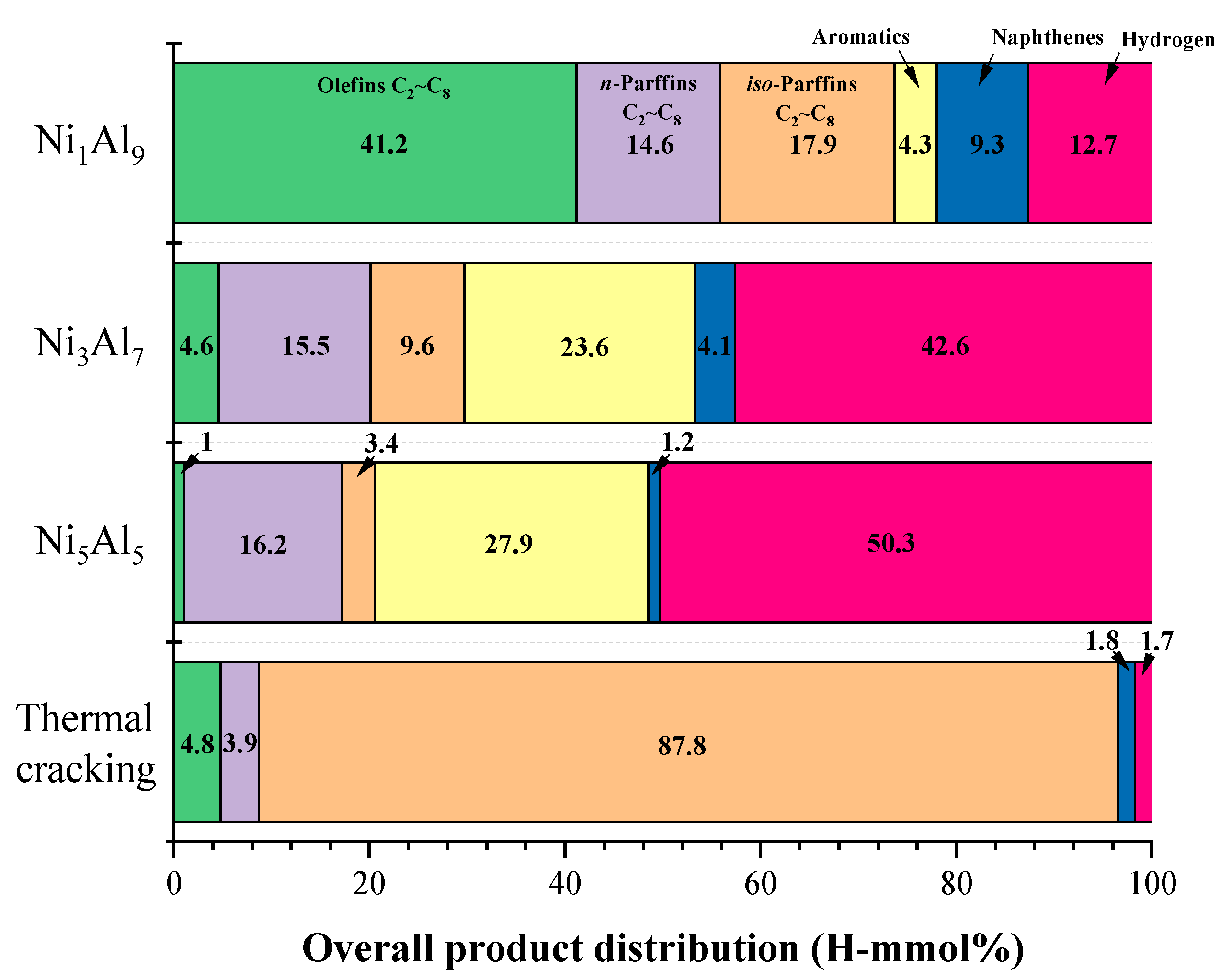
2.2.2. Product Distribution

Interestingly, in contrast with its high MCH conversion and gas yield, Ni5Al5 exhibited a heat sink of 2086.2 kJ/kg, which is much lower than that of Ni1Al9 (2636.5 kJ/kg). This is explained by the differences in the product selectivity and carbon deposition of the catalysts, which is discussed later in the product analysis results. Nevertheless, all catalysts performed better than sole thermal cracking. Thus, it must be emphasized that MCH endothermic cracking is a reaction that requires catalyst promotion.
Gaseous and liquid product analysis provides significant information about the reaction pathway of supercritical MCH catalytic cracking. The selectivity of the overall product for the NiAl2O4 catalysts with varying Ni contents is summarized in Table 5. The gaseous products were classified into hydrogen, light paraffins, and olefins, while the liquid products were classified into n-paraffins, iso-paraffins, olefins, aromatics, and naphthalenes. Figure 7 shows the gaseous product distribution. The main gaseous products were hydrogen followed by methane (light paraffin), while small amounts of other light paraffins and olefins were also present. Ni3Al7 and Ni5Al5 showed 42.5 and 50.4% selectivity toward hydrogen, values that are, respectively, 29.8 and 37.7% higher, than that displayed by Ni1Al9 (12.7%). Ni is in the same periodic group (Group 10) as Pt and Pd and exhibits outstanding metal properties in dehydrogenation reactions [32,33,34]. For Ni3Al7 and Ni5Al5, the dehydrogenation reaction proceeded more actively because of the presence of small Ni particles (9–10 nm) and their high dispersibility. Accordingly, the selectivity of toluene among the liquid products of these two catalysts was the highest at 19.94 and 22.6%, respectively, (Table 5), which can be interpreted as concrete evidence of the dehydrogenation reaction (Scheme 1). Generally, hydrogen is known to exhibit a positive effect on heat sink efficiency [35]. However, the previous heat sink results showed a different trend to that displayed by the hydrogen selectivity. Indeed, the hydrogen selectivity decreased in the order of Ni5Al5 (50.4 %) > Ni3Al7 (42.5 %) > Ni1Al9 (12.7 %), whereas that of the heat sink efficiency decreased in the order of Ni5Al5 (2086.2 kJ/kg) < Ni3Al7 (2159.1 kJ/kg) < Ni1Al9 (2636.5 kJ/kg). The cracking of linear paraffin-based fuels, requires a large amount of endothermic heat to produce hydrogen as the final product of the chain reaction. However, cycloparaffins such as MCH require relatively small amounts of heat because hydrogen is cracked by the metal at the beginning of the reaction. Therefore, it is suggested that the improvement in the hydrogen selectivity is not critically influenced by the increase in the heat sink efficiency. In addition, the methane and benzene selectivities were the second highest for Ni5Al5, suggesting that the reaction was terminated after a series reaction with the produced toluene and hydrogen. The formation of benzene and coke from toluene is competitive, and is thought to exhibit significant influence on coke formation inhibition (Scheme 1) [36]. On the other hand, Ni1Al9 exhibits properties that limit its catalytic performance, including large Ni particles (20 nm) and low dispersibility (4.1%). However, it characteristically formed strong acid sites as a result of its high Al content. It is suggested that the formation of strong acid sites leads to ring opening and subsequent isomerization after dehydrogenation by Ni as an active site. Classically, saturated cycloparaffins are ring-opened by carbenium ions at the acid site after dehydrogenation by Ni metal [37]. Notably, compared to the other catalysts, Ni1Al9 showed remarkably higher selectivity toward olefin (41.2%) and iso-paraffin (17.9%) (Figure 8). Thus, Ni1Al9 can be described as a dual-function catalyst with two different active sites.

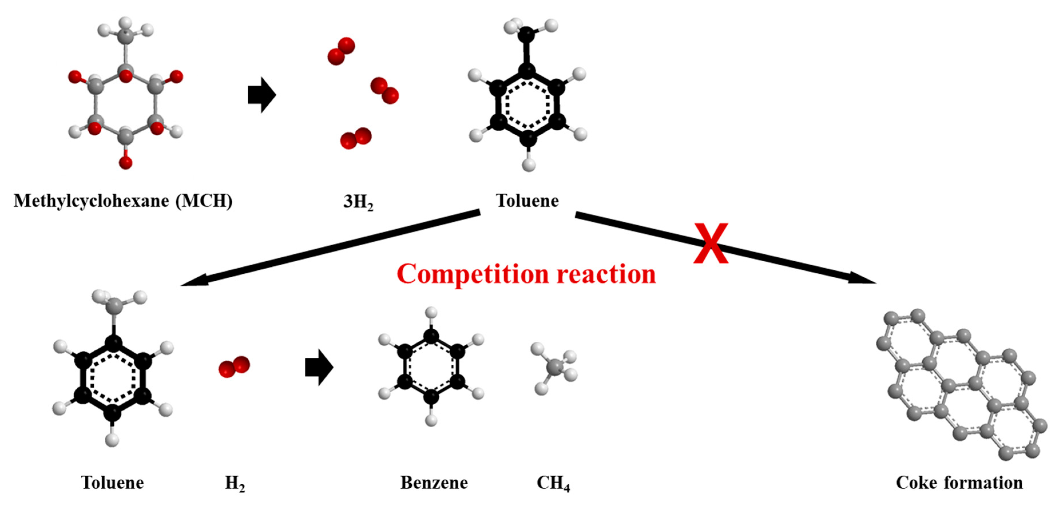
2.3. Carbon Formation

To clearly understand the characteristics of coke, its morphology and oxidation activity were next investigated through temperature-programmed oxidation (TPO) and SEM analysis of the spent catalysts (Figure 9). The TPO profiles were broadly divided into two combustion temperature regions, α and β, based on the Gaussian deconvolution peak, and further subdivided to accurately measure the area. Notably, a marked difference was observed in the deposited coke type depending on the Ni content. The signals observed at a relatively low temperature (<400 °C) in the TPO profiles corresponded to the combustion of non-fibrous or encapsulated carbon, whereas those observed at a relatively high temperature (˃400 °C) corresponded to filamentous carbon [38,39,40]. The variation in the coke oxidation activities of the three catalysts was attributed to the amount of Al2O3, while the amount of coke also played a significant role. Thus, as the amount of Al2O3 increased, the amount of coke increased in the order of Ni5Al5 (3.5 mg) < Ni3Al7 (10.34 mg) < Ni1Al9 (121.75 mg) (Table 6). In particular, Ni1Al9 formed up to 34.7-fold more coke than did the other catalysts, as is clearly observed in the Ni1Al9 scanning electron micrograph (Figure 9a). The catalyst surface was mostly covered with filamentous carbon, which is thought to be the main factor causing the pressure drop in 17 min. It is well known that the formation mechanism and structure of filamentous carbon are related to the state of the catalytically active species, which consists of a solid solution of carbon in the metal [41]. Therefore, it is suggested that the Ni1Al9 catalyst effectively proceeds to form nickel carbide due to the low dispersibility of Ni and strong acid sites. The olefins of unsaturated hydrocarbons formed by the strong acid sites promote the formation of filamentous carbon [42]. On the other hand, an increase in the nickel content not only increases the dispersion of Ni metal, but also decreases the amount of acid sites so that the formation of Ni carbide is suppressed. These results revealed that the α/β ratio increases with increasing Ni content, which is clear evidence of the inhibition of Ni carbide formation.

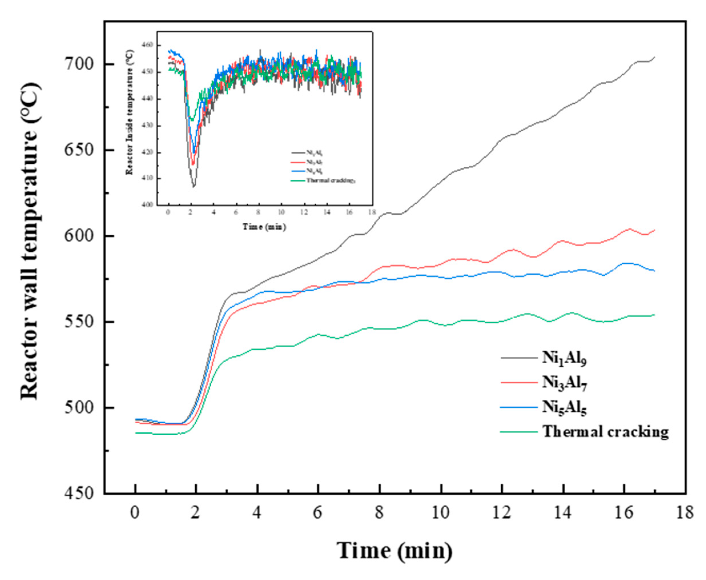
2.4. Gas Formation and Reactor Temperature Behavior

Figure 10 shows the gas formation profiles of thermal and catalytic cracking. Except for Ni5Al5, a decrease in gas formation was observed after 3 min in all the catalysts and thermal cracking. Interestingly, Ni1Al9 exhibited gas formation behavior similar to that observed with thermal cracking, but there were marked differences in the MCH conversion and coke formation. Thus, thermal cracking displayed a very low conversion of 6% and negligible coke formation. On the other hand, Ni1Al9 showed a relatively high conversion of 29.1% and produced a large amount (121.75 mg) of coke (Table 6). The strong acid sites and large Ni particles easily formed nickel carbide. Thus, the olefins in the high-concentration unsaturated hydrocarbon produced during the reaction resulted in the continuous formation of filamentous carbon. It is also presumed that in this process, gas formation was negligible and only coke was produced. Here, the effect of carbon formation on the heat sink is noteworthy. Figure 11 shows the behavior of the reactor internal and wall temperatures during the reaction. The experiment was maintained by proportional-integral-differential (PID) control based on the temperature inside the reactor at 450 °C. The inset in Figure 11 shows the behavior of the temperature inside the reactor. In both the catalytic and thermal cracking processes, the temperature inside the reactor was maintained at 450 ± 10 °C from 5 min of reaction until the reaction was terminated. In contrast, the reactor wall temperature (main figure in Figure 11) showed different results depending on the catalysts/thermal cracking. The difference between the reactor wall and internal temperatures is interpreted as heat absorption by the endothermic reaction, and this value can be expressed as an increase in the efficiency of the heat sink as it increases. Thus, the temperature in Ni1Al9 increased sharply, from 560 to 700 °C, 3 min after the beginning of the reaction, while that of Ni5Al5 remained between 550 and 600°C until the reaction was complete. These results are the reverse of the gas formation behavior, indicating that coke formation improves the heat sink efficiency.

3. Materials and Methods

3.1. Materials

Ni(NO3)2∙6H2O (≥97%), Al(NO3)3∙9H2O (≥98%), and NaOH (≥98%) were obtained from Sigma-Aldrich. Deionized (DI) water was used for all the syntheses.

3.2. Catalyst Preparation

The catalyst preparation method has been described in detail in our previous work [43]. Ni/Al2O3 catalysts with various Ni compositions (10 wt.%, 30 wt.%, and 50 wt.%) were prepared by a co-precipitation method. Briefly, a NaOH (2 M) solution was added dropwise into a Ni(NO3)2·6H2O and Al(NO3)3·9H2O mixed solution while maintaining a pH of 7–8. Subsequently, the precipitate was filtered and washed with DI water to remove any impurities. The resulting filter cake was dried in an oven at 110 °C for 24 h and then calcined at 500 °C for 4 h.

3.3. Catalytic Activity Evaluation

To evaluate the activity of supercritical MCH cracking, the experiment was performed at 4 MPa and 450 °C using a fixed bed reactor (Figure 12). The reactor was made of SUS316L stainless steel with a length of 310 mm and a half-inch inner diameter. The entire process was separated into fuel supply, reactor, product separation, collection, and analysis sections. The catalyst was loaded into the reactor in 0.2 g amounts using mash (No. 80). A thermocouple was placed on top of the catalyst layer. Before supplying the MCH, the reactor was pressurized to 4 MPa with ultrapure N2 and then maintained at 450 °C. The reduced temperature inside the reactor, from the fuel supply, was maintained by an electric heater equipped with a PID controller, and the consumed power was monitored to measure the heat capacity. The reaction was carried out for 17 min. The products that passed through the catalytic layer were separated into liquid and gas products using a two-stage condenser and then collected in vials and gas-tight bags (TEDLAR, 10 L). The liquid product was determined by offline gas chromatography (GC; Agilent 7890B; flame ionization detection (FID)) using a detailed hydrocarbon analysis method (DHA, ASTM D6730) [44,45]. The gas product was determined using a gas chromatograph (6500YL, Younglin) equipped with a flame ionization detector and GS-GasPro capillary column (30 m × 0.32 mm). The MCH conversion and product selectivity were calculated using the following equations:
Coversion   ( X ) = ( Initial   mole   of   MCH   Final   mole   of   MCH Initial   mole   of   MCH ) × 100
Selectivity   ( S ) = ( mole   of   each   product mole   of   totol   products ) × 100
Heat   sink   capacity   ( Q )   =   Electrical   power ( kW )   ×   Thermal   efficiency ( η )   Mass   flow   rate   of   n dodecane ( kg / s )
The power consumption of the electrical heater was measured during the catalytic cracking process to maintain isothermal reaction conditions of 450 °C. The heat loss to the environment is reflected by the thermal efficiency η. Thus, the power consumption during heating from room temperature (RT) to 450 °C under N2 flow was measured, and η was calculated as the ratio of the ideal sensible heat of N2 to the power consumption during the calibration test. The N2 flow rate was maintained at 2 L/min to produce turbulent conditions and thus prevent heat transfer limitation in the axial direction. A constant heat capacity (Cp) value of 30.93 kJ/k-mol K and ideal gas behavior were assumed for N2. The calibrated η value was 0.255 in the experiments. The heat sink capacity (Q) was calculated from Equation (3), assuming that the net power consumption was provided to maintain isothermal conditions against the endothermic reaction heat [46].

3.4. Catalyst Characterization

XRD patterns were obtained using a D/MAX-2500V X-ray diffractometer (Rigaku, Tokyo, Japan) equipped with Ni-filtered Cu Kα (λ = 0.154 nm) radiation at 40 kV and 200 mA. Bragg angles in the range 5–90° were collected by continuous scan mode at a rate of 5°/min. The mean crystallite diameters were determined using Scherrer’s equation. The reduced catalyst was treated with pure H2 (50 mL/min) for 1 h at 700 °C and then passivated by O2 vol. 1%/N2 (30 mL/min) at room temperature.
The N2 adsorption-desorption isotherms of the Ni/Al2O3 catalysts were obtained using a Micromeritics ASAP 2020 instrument. The Brunauer–Emmett–Teller (BET) surface area was calculated over the relative pressure range 0–1, while the pore size distribution was calculated by the Barrett–Joyner–Halender (BJH) method. Prior to measurement, a sample of approximately 0.2 g was heated at 200 °C for 2 h to exhaust gas temperature.
The surface images of the catalysts were observed using a field emission scanning electron microscope (FESEM, S-4700, Hitachi, Tokyo, Japan) operating at 12.0 kV. TEM analysis was performed using a JEOL JEM 1230 electron microscope (acceleration voltage: 120 kV). The mean particle size and particle size distribution were determined from more than 100 Ni particle sizes in the image of each catalyst.
NH3-TPD was also performed on the Bel-Cat-41 analyzer. Approximately 100 mg of each catalyst was reduced at 700 °C for 1 h under a flow of pure H2 and then cooled to 50 °C. Subsequently, pure H2 was switched to 2 vol.% NH3/He mixed gas and the sample surface was saturated. The catalyst was then outgassed with ultrapure He for 30 min and heated to 750 °C at 10 °C/min. Desorption profiles were recorded using a thermal conductivity detector (TCD).
Similarly, the TPO of the catalyst was carried out using a Bel-Cat-41 analyzer equipped with a TCD. The reacted catalysts were treated for 2 h under a flow of ultrapure N2 (flow rate: 1000 mL/min), at 500 °C, to remove the residual fuel. Subsequently, the fuel-residue-free catalyst was loaded into a quartz reactor and heated to 1100 °C at a ramping rate of 10 °C/min under 30 mL/min of mixed gas (21 vol.% O2/He).
The Ni metal surface area and dispersion were analyzed by the O2 pulse chemisorption method and performed using an AutoChem II 2920 equipped with a TCD. Approximately 0.01 g catalyst was reduced at 700 °C for 1 h under a flow of pure H2 and then cooled to 260 °C. Subsequently, impurities were removed for 30 min under ultrapure He (30 mL/min) and titrated with 5 vol.% O2/He [47,48].
Chemical bulk composition was measured using X-ray fluorescence spectroscopy (XRF) equipped with a Bruker S8 Tiger instrument using rhodium tubes operating at 4 kW. Analysis was conducted using calcined catalysts.

4. Conclusions

The catalytic activity of several NiAl2O4 spinel-based precursors with various Ni/Al ratios was evaluated for the cracking of MCH under supercritical conditions at 450 °C. Interestingly, the spinel compositions deficient in Ni or Al showed a significant difference in performance and physicochemical properties from those of the stoichiometric catalyst (Ni3Al7).
In the Ni1Al9 catalyst with insufficient Ni content, only the Al2O3 phase was observed, without the NiAl2O4 structure. This catalyst not only formed the largest Ni particles with an average diameter of 20 nm, owing to the irregularly arranged Ni, but also formed abundant strong acid sites due to the high Al content. As a result, the unsaturated hydrocarbons produced by the Lewis acid sites led to the formation of nickel carbide and subsequent carbon deposition. Conversely, the Ni5Al5 catalyst, with insufficient Al content, preserved the NiAl2O4 spinel structure, even though a small amount of NiO was detected. The increased excess Ni in the lattice prevented crystal growth and agglomeration by inhibiting Ni sintering by the NiAl2O4 spinel. This resulted in a relative increase in the Ni metal surface area (63.2 m2/g Ni Content) and Ni dispersibility (10%). Well-dispersed Ni in the absence of strong Lewis acid sites not only caused dehydrogenation, but also showed coke inhibitory effects.
The heat sink efficiency trend observed for the inspected alumina-assisted nickel catalyst derived from a substoichiometric spinel base suggested that it is related to coke formation. Indeed, compared to the results attained for Ni5Al5, Ni1Al9 exhibited the highest heat sink of 2636.5 kJ/kg, despite its significantly lower conversion (29.1%) and gas yield (2.5%). However, this catalyst caused a pressure drop within 17 min of reaction, owing to the abundant coke formation (121.75 mg). On the other hand, although Ni5Al5 displayed a lower heat sink of 2086.2 kJ/kg, it maintained the stability of the catalyst without pressure strengthening, owing to its excellent resistance to carbon deposition.
Therefore, for the cracking of MCH using an alumina-supported nickel catalyst derived from a substoichiometric spinel base, a Ni5Al5 catalyst with excellent resistance to coke and hydrogen production capability is preferred.

Author Contributions

K.H.S. (methodology, data curation, writing original draft preparation, formal analysis), S.K.J. (supervision, investigation, funding acquisition), B.H.J. (supervision, investigation, funding acquisition), K.-Y.L. (supervision), and H.J.K. (Conceptualization, writing, reviewing, and editing, project administration). All authors have read and agreed to the published version of the manuscript.

Funding

This research was funded by the Grant-in-aid from the Korean Agency for Defense Development (ADD) funded by the Korean Defense Acquisition Program Administration (DAPA) and the Korean Ministry of National Defense (MND).

Data Availability Statement

Data available in a publicly accessible repository.

Conflicts of Interest

The authors declare no conflict of interest.

References

  1. Edwards, T. Liquid Fuels and Propellants for Aerospace Propulsion: 1903–2003. J. Propuls. Power 2003, 19. [Google Scholar] [CrossRef]
  2. Kay, I.W.; Peschke, W.T.; Guilet, R.N. Hydrocarbon-Fueled Scramjet Combustor Investigation. J. Propuls. Power 1992, 8, 507–512. [Google Scholar] [CrossRef]
  3. Puri, P.; Ma, F.; Choi, J.Y.; Yang, V. Ignition characteristics of cracked JP-7 fuel. Combust. Flame 2005, 142, 454–457. [Google Scholar] [CrossRef]
  4. Heneghan, S.P.; Martel, C.R.; Williams, T.F.; Ballal, D.R. Studies of jet thermal stability in a flowing system. In Proceedings of the ASME International Gas Turbine and Aeroengine Congress and Exposition: Coal, Biomass and Alternative Fuels; Combustion and Fuels; Oil and Gas Applications; Cycle Innovations, Cologne, Germany, 1–4 June 1992; Volume 3, pp. 1–7. [Google Scholar] [CrossRef] [Green Version]
  5. Balster, L.M.; Corporan, E.; DeWitt, M.J.; Edwards, J.T.; Ervin, J.S.; Graham, J.L.; Lee, S.Y.; Pal, S.; Phelps, D.K.; Rudnick, L.R.; et al. Development of an advanced, thermally stable, coal-based jet fuel. Fuel Process. Technol. 2008, 89, 364–378. [Google Scholar] [CrossRef]
  6. Klavetter, E.A.; Martin, S.J.; Wessendorf, K.O. Monitoring Jet Fuel Thermal Stability Using a Quartz Crystal Microbalance. Energy Fuels 1993, 7, 582–588. [Google Scholar] [CrossRef]
  7. Kim, J.; Hee, S.; Chun, B.; Hun, B.; Sik, J.; Hyun, S. Improvement of the heats of reaction in endothermic reactions of methylcyclohexane with zeolites. Catal. Today 2012, 185, 47–53. [Google Scholar] [CrossRef]
  8. Ho, T.C.; Thilakaratne, R.; Gardner, D.W.; Brown, R.C.; Tessonnier, J. Thermal Stability of Aluminum-Rich ZSM-5 Zeolites and Consequences on Aromatization Reactions. J. Phys. Chem. C 2016, 120, 20103–20113. [Google Scholar]
  9. Mihindou-koumba, P.C.; Cerqueira, H.S.; Magnoux, P.; Guisnet, M. Methylcyclohexane Transformation over HFAU, HBEA, and HMFI Zeolites: II. Deactivation and Coke Formation. Ind. Eng. Chem. Res. 2001, 40, 1042–1051. [Google Scholar] [CrossRef]
  10. Wojciechowski, B.W. The Reaction Mechanism of Catalytic Cracking: Quantifying Activity, Selectivity, and Catalyst Decay. Catal. Rev. 1998, 40, 209–328. [Google Scholar] [CrossRef]
  11. Regali, F.; Francesca, L.; Maria, A.; Boutonnet, M.; Järås, S. Applied Catalysis A: General Hydroconversion of n-hexadecane on Pt/silica-alumina catalysts: Effect of metal loading and support acidity on bifunctional and hydrogenolytic activity. Appl. Catal. A Gen. 2014, 469, 328–339. [Google Scholar] [CrossRef]
  12. Yue, L.; Lu, X.; Chi, H.; Guo, Y.; Xu, L.; Fang, W.; Li, Y.; Hu, S. Heat-sink enhancement of decalin and aviation kerosene prepared as nanofluids with palladium nanoparticles. Fuel 2014, 121, 149–156. [Google Scholar] [CrossRef]
  13. Nixon, A.C.; Ackerman, G.H.; Hawthorme, R.D.; Ritchie, A.W.; Henderson, H.T.; Bjorklund, I.S. Vaporization and Endothermic Fuels for Advanced Engine Applications: AFAPL TDR 64-117 Parts I, II, and III; Defense Technical Information Center: Fort Belvoir, VA, USA, 1964.
  14. Yin, S.; Chin, Y.; Amiridis, M.D. Hydrogen production via the catalytic cracking of ethane over Ni/SiO2 catalysts. Appl. Catal. A Gen. 2006, 300, 8–13. [Google Scholar] [CrossRef]
  15. He, Z.; Jiao, Y.; Wang, J.; Chen, Y. Journal of Analytical and Applied Pyrolysis Effects of M(Zr, Nb, Y) modifiers on the catalytic performance of Ni/Ce-Al2O3 bimetallic catalyst in steam reforming of n-ecane. J. Anal. Appl. Pyrolysis 2016, 122, 142–150. [Google Scholar] [CrossRef]
  16. Taherian, Z.; Khataee, A.; Orooji, Y. Facile synthesis of yttria-promoted nickel catalysts supported on MgO-MCM-41 for syngas production from greenhouse gases. Renew. Sustain. Energy Rev. 2020, 134, 110130. [Google Scholar] [CrossRef]
  17. Taherian, Z.; Shahed Gharahshiran, V.; Khataee, A.; Meshkani, F.; Orooji, Y. Comparative study of modified Ni catalysts over mesoporous CaO-Al2O3 support for CO2/methane reforming. Catal. Commun. 2020, 145, 106100. [Google Scholar] [CrossRef]
  18. Jime, C.; Boukha, Z.; Rivas, B.D.; Gonza, J.R.; Gutie, J.I. Behavior of Coprecipitated NiAl2O4/Al2O3 Catalysts for Low-Temperature Methane Steam Reforming. Energy Fuels 2014, 28, 7109–7121. [Google Scholar] [CrossRef]
  19. Enger, B.C.; Lødeng, R.; Walmsley, J.; Holmen, A. Inactive aluminate spinels as precursors for design of CPO and reforming catalysts. Appl. Catal. A Gen. 2010, 383, 119–127. [Google Scholar] [CrossRef]
  20. Ross, J.R.H.; Steel, M.C.F.; Zeini-Isfahani, A. Evidence for the participation of surface nickel aluminate sites in the steam reforming of methane over nickel/alumina catalysts. J. Catal. 1978, 52, 280–290. [Google Scholar] [CrossRef]
  21. Christensen, K.O.; Chen, D.; Lødeng, R.; Holmen, A. Effect of supports and Ni crystal size on carbon formation and sintering during steam methane reforming. Appl. Catal. A Gen. 2006, 314, 9–22. [Google Scholar] [CrossRef]
  22. Diarra, M.; Amara, H.; Ducastelle, F.; Bichara, C. Carbon solubility in nickel nanoparticles: A grand canonical Monte Carlo study. Phys. Status Solidi Basic Res. 2012, 249, 2629–2634. [Google Scholar] [CrossRef]
  23. Jenness, G.R.; Christiansen, M.A.; Caratzoulas, S.; Vlachos, D.G.; Gorte, R.J. Site-dependent Lewis acidity of γ-Al2O3 and its impact on ethanol dehydration and etherification. J. Phys. Chem. C 2014, 118, 12899–12907. [Google Scholar] [CrossRef]
  24. Stytsenko, V.D. Surface modified bimetallic catalysts: Preparation, characterization, and applications. Appl. Catal. A Gen. 1995, 126, 1–26. [Google Scholar] [CrossRef]
  25. Sahli, N.; Petit, C.; Roger, A.C.; Kiennemann, A.; Libs, S.; Bettahar, M.M. Ni catalysts from NiAl2O4 spinel for CO2 reforming of methane. Catal. Today 2006, 113, 187–193. [Google Scholar] [CrossRef]
  26. Otero Areán, C.; Pearroya Mentruit, M.; López López, A.J.; Parra, J.B. High surface area nickel aluminate spinels prepared by a sol-gel method. Coll. Surfaces A Physicochem. Eng. Asp. 2001, 180, 253–258. [Google Scholar] [CrossRef]
  27. Deraz, N.M. Synthesis and characterization of nano-sized nickel aluminate spinel crystals. Int. J. Electrochem. Sci. 2013, 8, 5203–5212. [Google Scholar]
  28. Rahbar Shamskar, F.; Rezaei, M.; Meshkani, F. The influence of Ni loading on the activity and coke formation of ultrasound-assisted co-precipitated Ni–Al2O3 nanocatalyst in dry reforming of methane. Int. J. Hydrogen Energy 2017, 42, 4155–4164. [Google Scholar] [CrossRef] [Green Version]
  29. Sun, Y.; Jiang, E.; Xu, X.; Wang, J.; Li, Z. Supplied Oxygen Properties of NiO/NiAl2O4 in Chemical Looping Re-Forming of Biomass Pyrolysis Gas: The Influence of Synthesis Method. ACS Sustain. Chem. Eng. 2018, 6, 14660–14668. [Google Scholar] [CrossRef]
  30. Millet, M.M.; Frei, E.; Algara-Siller, G.; Schlögl, R.; Tarasov, A. Surface titration of supported Ni catalysts by O2-pulse thermal analysis. Appl. Catal. A Gen. 2018, 566, 155–163. [Google Scholar] [CrossRef]
  31. Choong, C.K.S.; Huang, L.; Zhong, Z.; Lin, J.; Hong, L.; Chen, L. Effect of calcium addition on catalytic ethanol steam reforming of Ni/Al2O3: II. Acidity/basicity, water adsorption and catalytic activity. Appl. Catal. A Gen. 2011, 407, 155–162. [Google Scholar] [CrossRef]
  32. Wang, Y.; Shah, N.; Huffman, G.P. Pure hydrogen production by partial dehydrogenation of cyclohexane and methylcyclohexane over nanotube-supported Pt and Pd catalysts. Energy Fuels 2004, 18, 1429–1433. [Google Scholar] [CrossRef]
  33. Iwasa, N.; Takezawa, N. New supported Pd and Pt alloy catalysts for steam reforming and dehydrogenation of methanol. Top. Catal. 2003, 22, 215–224. [Google Scholar] [CrossRef]
  34. Luo, Q.; Feng, G.; Beller, M.; Jiao, H. Formic acid dehydrogenation on Ni(111) and comparison with Pd(111) and Pt(111). J. Phys. Chem. C 2012, 116, 4149–4156. [Google Scholar] [CrossRef]
  35. Sobel, D.R.; Spadaccini, L.J. Hydrocarbon Fuel Cooling Technologies for Advanced Propulsion. J. Eng. Gas Turbines Power. 1997, 119, 344–351. [Google Scholar] [CrossRef]
  36. Korus, A.; Samson, A.; Szle, A.; Katelbach-woz, A. Pyrolytic toluene conversion to benzene and coke over activated carbon in a fixed-bed reactor. Fuel 2017, 207, 283–292. [Google Scholar] [CrossRef]
  37. Song, Y.; Lin, W.; Guo, X.; Dong, L.; Mu, X.; Tian, H.; Wang, L. Aromatization and isomerization of methylcyclohexane over Ni catalysts supported on different supports. Green Energy Environ. 2019, 4, 75–82. [Google Scholar] [CrossRef]
  38. Castaño, P. Role of oxygenates and effect of operating conditions in the deactivation of a Ni supported catalyst during the steam reforming of bio-oil. Green Chem. 2017, 19, 4315–4333. [Google Scholar] [CrossRef]
  39. Montero, C.; Ochoa, A.; Castaño, P.; Bilbao, J.; Gayubo, A.G. Monitoring Ni0 and coke evolution during the deactivation of a Ni/La2O3– αAl2O3 catalyst in ethanol steam reforming in a fluidized bed. J. Catal. 2015, 331, 181–192. [Google Scholar] [CrossRef]
  40. Wang, S.; Lu, G.Q.M. A Comprehensive Study on Carbon Dioxide Reforming of Methane over Ni/γ-Al2O3 Catalysts. Ind. Eng. Chem. Res. 1999, 2615–2625. [Google Scholar] [CrossRef]
  41. Zaikovskii, V.I.; Chesnokov, V.V.; Buyanov, R.A. The Relationship between the State of Active Species in a Ni/Al2O3 Catalyst and the Mechanism of Growth of Filamentous Carbon 1. Kinet. Catal. 2001, 42, 813–820. [Google Scholar] [CrossRef]
  42. Bokx, D.E. The Formation of Filamentous Carbon on Iron and Nickel Catalysts. J. Catal. 1985, 480, 468–480. [Google Scholar] [CrossRef] [Green Version]
  43. Choi, E.G.; Song, K.H.; An, S.R.; Lee, K.Y.; Youn, M.H.; Park, K.T.; Jeong, S.K.; Kim, H.J. Cu/ZnO/AlOOH catalyst for methanol synthesis through CO2 hydrogenation. Korean J. Chem. Eng. 2018, 35, 73–81. [Google Scholar] [CrossRef]
  44. ASTM D6730-01: Standard Test Method for Determination of Individual Components in Spark Ignition Engine Fuels by 100–Metre Capillary (with Precolumn) High-Resolution Gas Chromatography; ASTM International: West Conshohocken, PA, USA, 2011.
  45. Song, K.H.; Jeong, S.K.; Jeong, B.H.; Lee, K.Y.; Kim, H.J. Acid/base-treated activated carbon catalysts for the low-temperature endothermic cracking of n-dodecane with applications in hypersonic vehicle heat management systems. Catalysts 2020, 10, 1149. [Google Scholar] [CrossRef]
  46. Song, K.H.; Jeong, S.K.; Park, K.T.; Lee, K.Y.; Kim, H.J. Supercritical catalytic cracking of n-dodecane over air-oxidized activated charcoal. Fuel 2020, 276, 118010. [Google Scholar] [CrossRef]
  47. Anjaneyulu, C.; Naveen Kumar, S.; Vijay Kumar, V.; Naresh, G.; Bhargava, S.K.; Chary, K.V.R.; Venugopal, A. Influence of la on reduction behaviour and Ni metal surface area of Ni-Al2O3 catalysts for COx free H2 by catalytic decomposition of methane. Int. J. Hydrog. Energy 2015, 40, 3633–3641. [Google Scholar] [CrossRef]
  48. Jiménez-González, C.; Boukha, Z.; De Rivas, B.; Delgado, J.J.; Cauqui, M.Á.; González-Velasco, J.R.; Gutiérrez-Ortiz, J.I.; López-Fonseca, R. Structural characterisation of Ni/alumina reforming catalysts activated at high temperatures. Appl. Catal. A Gen. 2013, 466, 9–20. [Google Scholar] [CrossRef]
Figure 1. X-ray diffractograms of NiAl2O4 with various Ni/Al ratios: (a) catalysts before reduction and (b) catalysts after reduction.
Catalysts 11 00323 g001
Figure 2. Scanning electron micrographs of the NiAl2O4 catalysts with various Ni/Al ratios: (ac) calcined catalysts and (df) reduced catalysts.
Catalysts 11 00323 g002
Figure 3. Respective transmission electron micrographs and Ni particle size distributions of the reduced NiAl2O4 catalysts with various Ni/Al ratios: (a,d) Ni1Al9, (b,e) Ni3Al7, and (c,f) Ni5Al5.
Catalysts 11 00323 g003
Figure 4. Pore size distribution and N2 adsorption-desorption isotherms of the NiAl2O4 catalysts with various Ni/Al ratios: (a,c) catalysts before reduction and (b,d) catalysts after reduction.
Catalysts 11 00323 g004
Figure 5. NH3 temperature-programmed desorption (NH3-TPD) profiles of the NiAl2O4 catalysts with various Ni/Al ratios.
Catalysts 11 00323 g005
Figure 6. Conversions, gas yields, and heat sinks of the NiAl2O4 catalysts with various Ni/Al ratios at 450 °C and 4 MPa.
Catalysts 11 00323 g006
Figure 7. Gaseous product distributions at 450 °C and 4 MPa.
Catalysts 11 00323 g007
Figure 8. Overall product distributions at 450 °C and 4 MPa.
Catalysts 11 00323 g008
Scheme 1. Possible reaction pathways for dehydrogenation aromatization of the Ni5Al5 catalyst.
Catalysts 11 00323 sch001
Figure 9. Scanning electron micrographs and temperature-programmed oxidation (TPO) profiles of the spent NiAl2O4 catalysts of various Ni/Al ratios: (a,d) Ni1Al9, (b,e) Ni3Al7, and (c,f) Ni5Al5.
Catalysts 11 00323 g009
Figure 10. Gas formation profiles at 450 °C and 4 MPa.
Catalysts 11 00323 g010
Figure 11. Reactor inside and wall temperature profiles during methylcyclohexane (MCH) cracking.
Catalysts 11 00323 g011
Figure 12. Experimental setup for the catalytic cracking of n-dodecane: (1) fuel container, (2) dosing pump, (3) N2 gas cylinder, (4) gas filter, (5) mass flow controller, (6) check valve, (7) K-type thermocouple, (8) pressure gauge, (9) on/off valve, (10) electrical heater, (11) differential pressure gauge, (12) water condenser, (13) back-pressure regulator, (14) gas-liquid separator, (15) liquid collecting vial, (16) wet gas meter, (17) gas collecting bag, (18) gas chromatograph for analysis of gaseous products, and (19) gas chromatograph for analysis of liquid products.
Catalysts 11 00323 g012
Table 1. Ni crystallite size determined by X-ray diffraction (XRD), transition electron microscopy (TEM), and O2 chemisorption of the NiAl2O4 catalysts with various Ni/Al ratios (after reduction).
SampledNi, nm (XRD)dNi, nm (TEM)dNi, nm (O2 Chemisorption)
Ni1Al920.820.920.7
Ni3Al79.59.39.6
Ni5Al510.410.810.7
Table 2. Physicochemical properties of the NiAl2O4 catalysts with various Ni/Al ratios.
SampleNi Metal Surface Area,
m2/g Ni Content
Ni Dispersion,
%
Calcined SamplesReduced Samples
SBET, m2/gVp, cm3/gdp, nmSBET, m2/gVp, cm3/gdp, nm
Ni1/Al927.44.1316.11.1013.5291.81.1015.1
Ni3/Al765.19.42540.6813.9210.30.6615.7
Ni5/Al563.210251.70.6611.5190.00.6514.1
Table 3. Bulk and surface components of the NiAl2O4 catalysts with various Ni/Al ratios.
SampleXRF (Bulk Composition)
Ni,
wt. %
Al,
wt. %
Ni/Al
Ni1/Al99.390.70.10
Ni3/Al727.272.80.35
Ni5/Al552.647.41.20
Table 4. Acid site densities for the NiAl2O4 catalysts with various Ni/Al ratios determined from the NH3 temperature-programmed desorption (NH3-TPD) profiles.
CatalystWeak Acid Sites
(α)
(μmol-NH3/g-cat)
Medium Acid Sites
(β)
(μmol-NH3/g-cat)
Strong Acid Sites
(γ)
(μmol-NH3/g-cat)
Total Acid Sites
(μmol-NH3/g-cat)
Ni1Al91.734.327.163
Ni3Al713.723.837.6
Ni5Al59.112.121.2
Table 5. Product distribution of methylcyclohexane (MCH) catalytic cracking based on H-mmol (%) and C-mmol (%).
Ni1Al9Ni3Al7Ni5Al5Thermal Cracking
Gas Products
H2Hydrogen12.72 42.5250.41.66
CH4Methane6.01 13.8615.440.4
C2H6Ethane4.00 0.880.490.07
C2H4Ethylene0.57 0.120.190.25
C3H8Propane3.15 0.70.190.29
C3H6Propylene2.42 0.480.06
C4H10n-Butane0.41 0.080.19
iso-Butane0.38 0.10.09
C4H81-Butene0.84 0.180.1
tran-2-Butene0.61 0.120.01
cis-2-Butene4.80 1.150.110.55
iso-Butene0.14 0.030.02
C4H61,3-butadiene 3.26
Alkanes13.95 15.62 16.40 0.76
Alkenes9.38 2.08 0.49 4.06
Alkenes/alkanes0.67 0.13 0.03 5.34
(hydrogen + alkenes)/alkanes1.58 2.86 3.10 7.53
Liquid Products
n-paraffins
C7H16n-heptane1.10
iso-paraffins
C5H12i-pentane15.78 8.552.6686.89
C7H162,3-dimethylpentane-20.90
3-ethylpentane0.86
3,3-dimethylpentane 0.39
2-methylhexane 0.790.170.93
3-ethylpentane 0.18
Olefins
C5H10t-pentene-20.86
2-methylbutene-21.27
c-pentene-21.02
C6H12t-hexene-20.70
2-methylpentene-2 10.49
C7H121,6-heptadiene4.42 0.990.240.89
C7H144,4-dimethyl-c-pentene-20.48
2,4-dimethylpentene-11.49 0.18
5-methylhexene-10.58 0.19
5-methyl-t-hexene-213.16 2.06
5-methyl-c-hexene-24.68 1.030.230.98
heptene-10.52
3-methyl-c-hexene-30.68
3-methyl-t-hexene-3 0.18
c-heptene-30.54
t-heptene-20.87
Naphthenes
C5H8Cyclopentene0.49
C6H10Cyclohexene3.58 3.10.63
C6H12Ethylcyclopentane4.13 0.590.27
C7H141t,3-dimethylcyclopentane1.08 0.460.261.77
Aromatics
C6H6Benzene 3.14.45
C7H8Toluene4.27 19.9422.6
C8H101,3-dimethylbenzene 0.50.81
Aromatics (total)4.27 23.54 27.86 0.00
Conversion (%)29.10 31.935.46.1
Gaseous products36.05 60.22 67.29 6.48
Liquid products63.95 39.78 32.71 93.52
Mass of coke (mg, 17 min)121.7510.344.26
Carbon balance Error (%)8.59 2.462.450.82
Hydrogen balanceError (%)3.265.866.120.45
Table 6. Peak allocation and quantification corresponding to the temperature-programmed oxidation (TPO) profile results.
Sampleα (mg)
Encapsulated Carbon
β (mg)
Filamentous Carbon
Total (mg)α/β Ratio
Ni1Al933.1388.62121.750.37
Ni3Al75.924.4210.341.33
Ni5Al52.750.753.503.67
Publisher’s Note: MDPI stays neutral with regard to jurisdictional claims in published maps and institutional affiliations.

