
CuO-In2O3 Catalysts Supported on Halloysite Nanotubes for CO2 Hydrogenation to Dimethyl Ether


 , , , and
Abstract
:1. Introduction
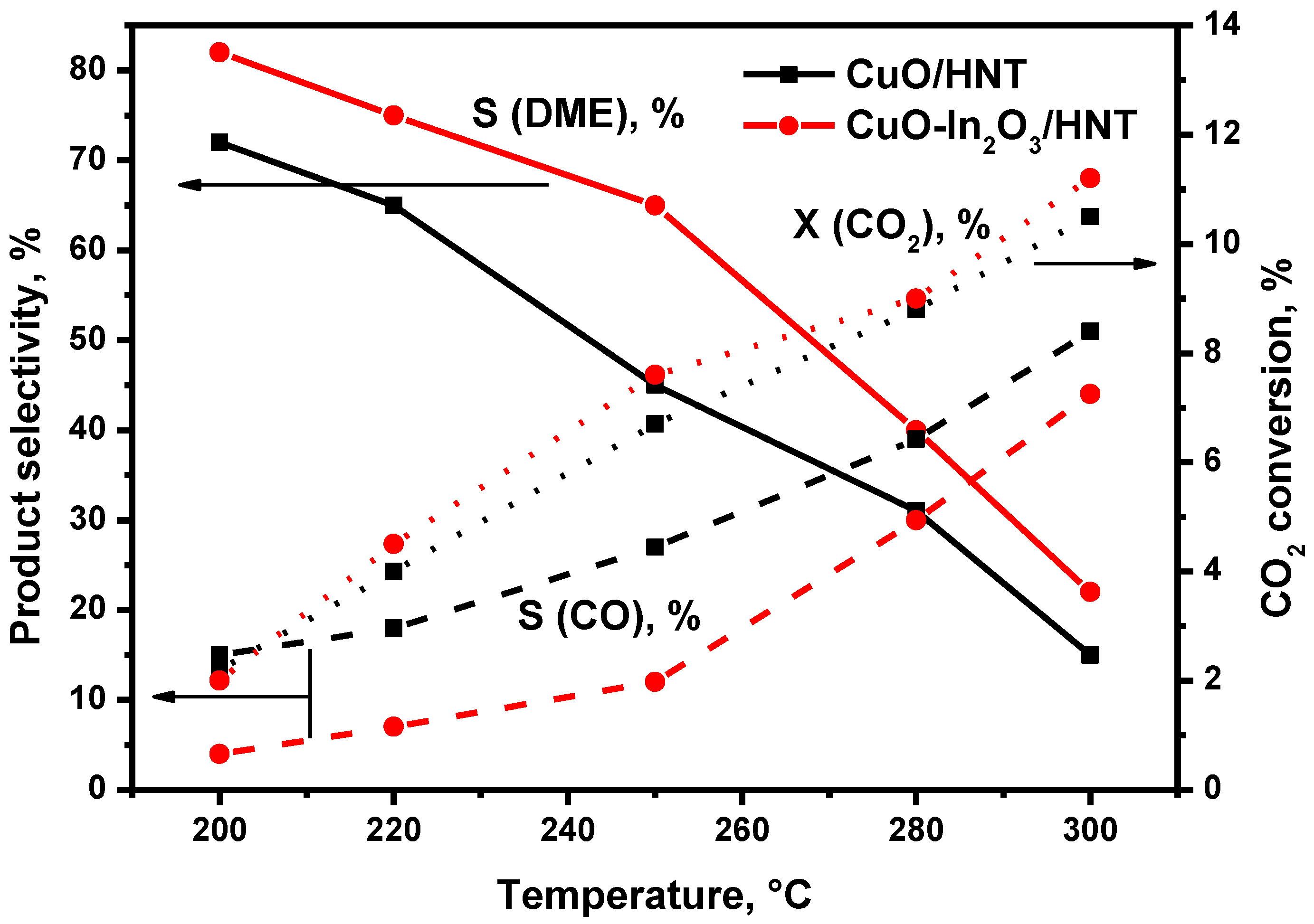
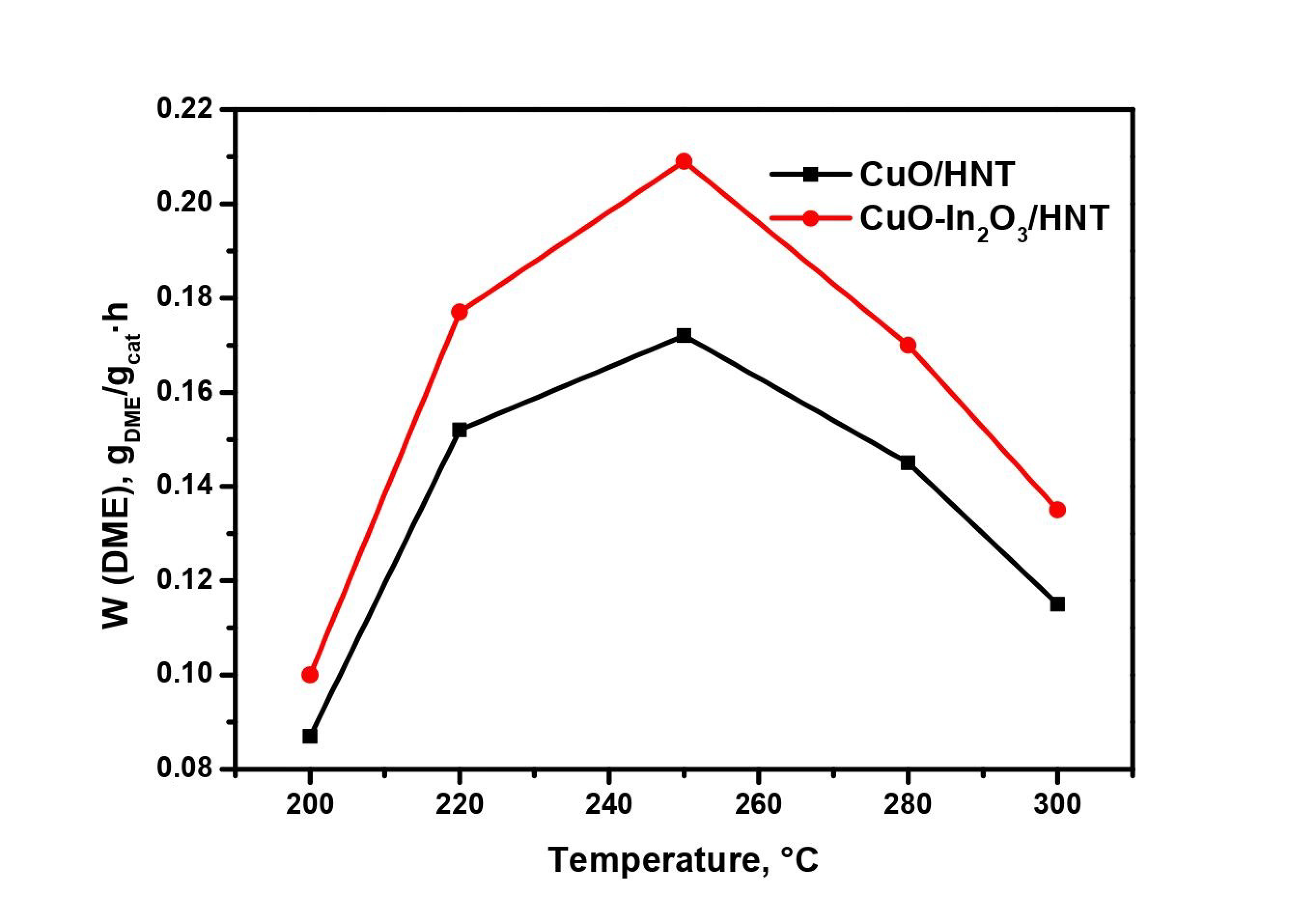
2. Results
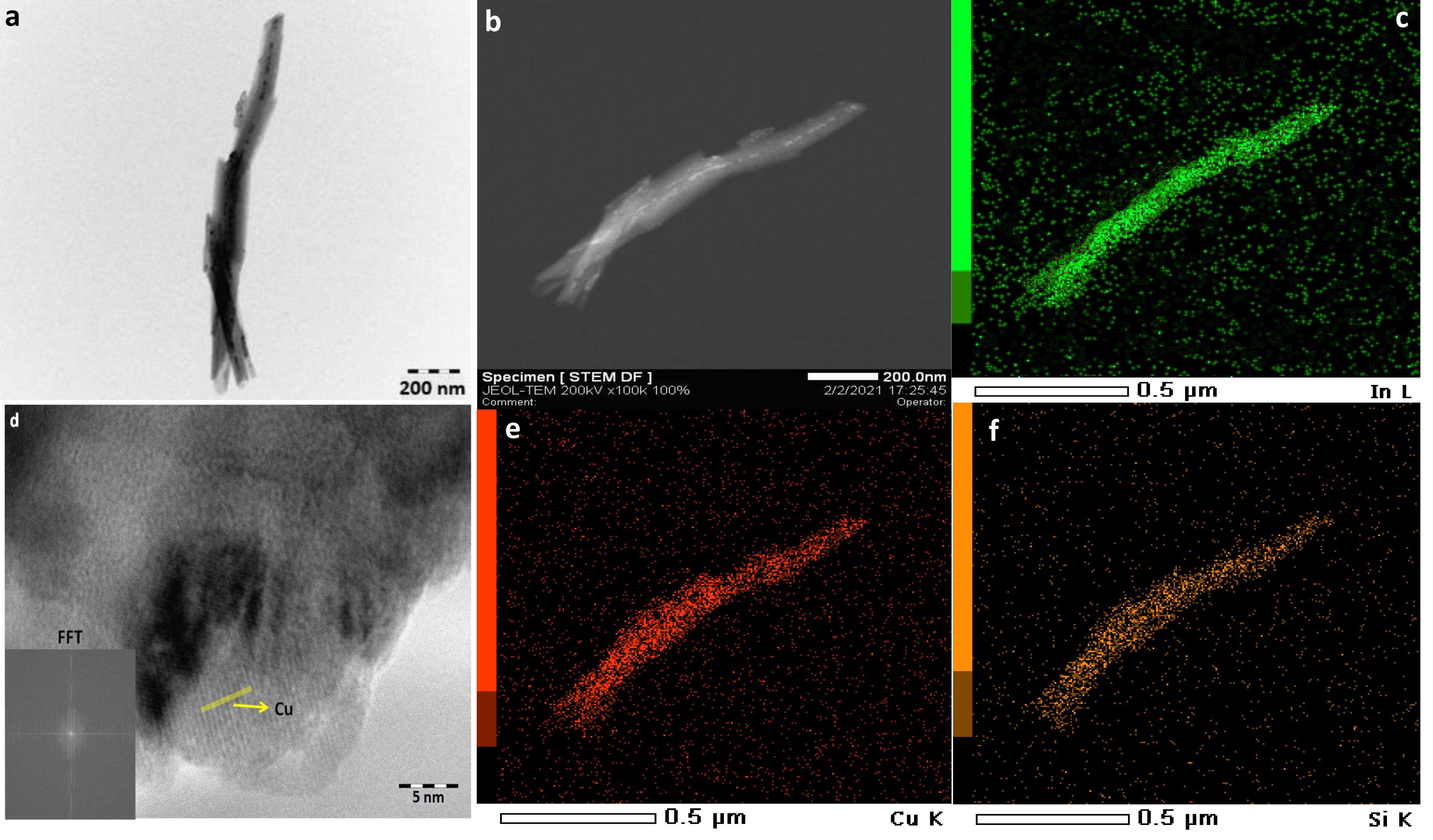
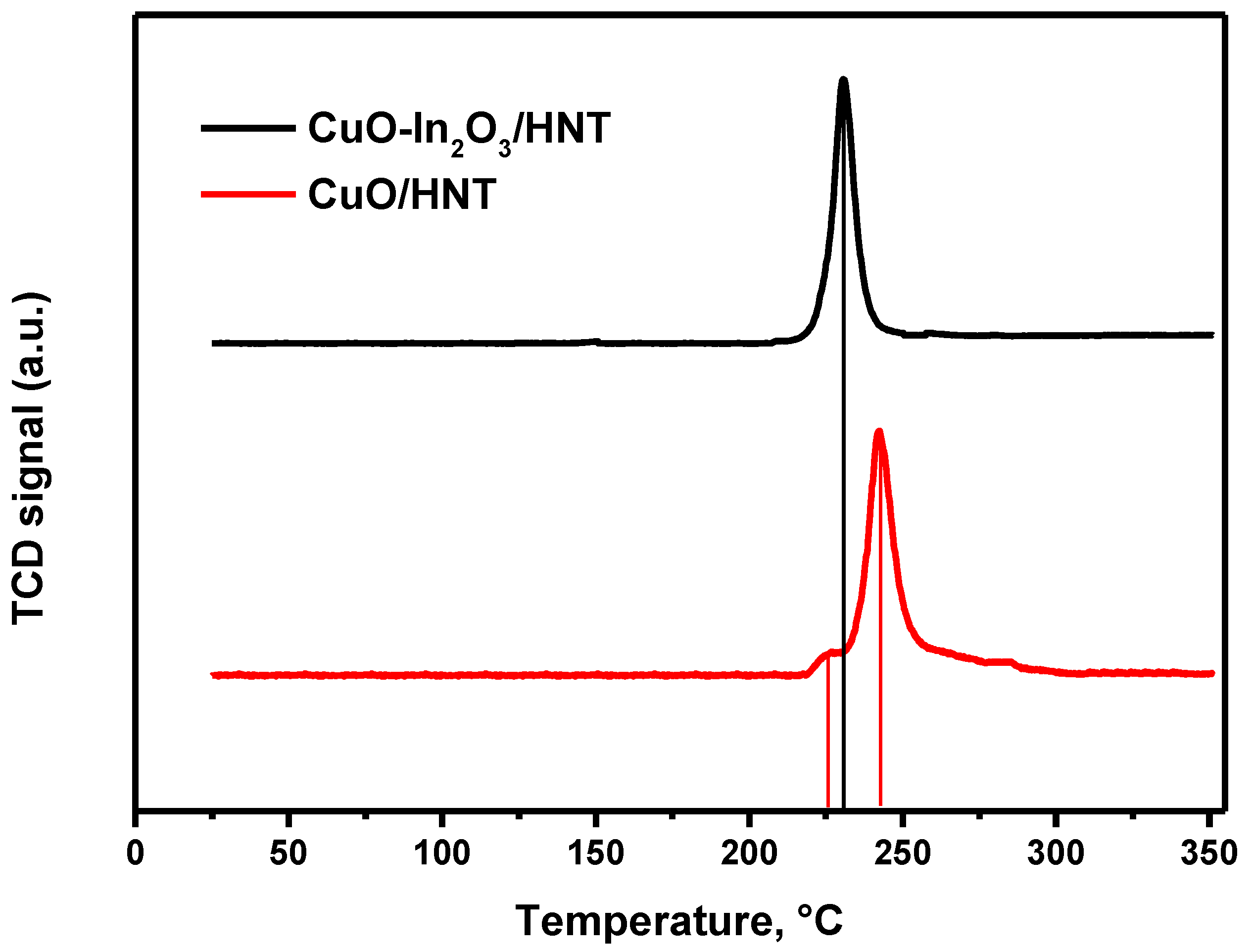
Characterization of Catalysts
3. Materials and Methods
4. Conclusions
Supplementary Materials
Author Contributions
Funding
Conflicts of Interest
References
- Federsel, C.; Jackstell, R.; Beller, M. State-of-the-art catalysts for hydrogenation of carbon dioxide. Angew. Chem. Int. Ed. 2010, 49, 6254–6257. [Google Scholar] [CrossRef]
- Shikada, T.; Ohno, Y.; Ogawa, T.; Ono, M.; Mizuguchi, M.; Tomura, K.; Fujimoto, K. Direct synthesis of dimethyl ether form synthesis gas. Stud. Surf. Sci. Catal. 1998, 119, 515–520. [Google Scholar]
- Azizi, Z.; Rezaeimanesh, M.; Tohidian, T.; Rahimpour, M.R. Dimethyl ether: A review of technologies and production challenges. Chem. Eng. Process. Process. Intensif. 2014, 82, 150–172. [Google Scholar] [CrossRef]
- Catizzone, E.; Bonura, G.; Migliori, M.; Frusteri, F.; Giordano, G. CO2 recycling to dimethyl ether: State-of-the-art and perspectives. Molecules 2018, 23, 31. [Google Scholar] [CrossRef] [PubMed] [Green Version]
- Sun, J.; Yang, G.; Yoneyama, Y.; Tsubaki, N. Catalysis chemistry of dimethyl ether synthesis. ACS Catal. 2014, 4, 3346–3356. [Google Scholar] [CrossRef]
- California Environmental Protection Agency. California Dimethyl EtherMultimedia Evaluation, Tier 1; California Environmental Protection Agency: Sacramento, CA, USA, 2015. [Google Scholar]
- Snytnikov, P.V.; Badmaev, S.D.; Volkova, G.G.; Potemkin, D.I.; Zyryanova, M.M.; Belyaev, V.D.; Sobyanin, V.A. Catalysts for hydrogen production in a multifuel processor by methanol, dimethyl ether and bioethanol steam reforming for fuel cell applications. Int. J. Hydrog. Energy 2012, 37, 16388–16396. [Google Scholar] [CrossRef]
- Semelsberger, T.A.; Borup, R.L.; Greene, H.L. Dimethyl ether (DME) as an alternative fuel. J. Power Sources 2006, 156, 497–511. [Google Scholar] [CrossRef]
- Kunkes, E.L.; Studt, F.; Abild-Pedersen, F.; Schlögl, R.; Behrens, M. Hydrogenation of CO2 to methanol and CO on Cu/ZnO/Al2O3: Is there a common intermediate or not? J. Catal. 2015, 328, 43–48. [Google Scholar] [CrossRef] [Green Version]
- Ye, J.; Liu, C.; Mei, D.; Ge, Q. Active oxygen vacancy site for methanol synthesis from CO2 hydrogenation on In2O3 (110): A DFT study. ACS Catal. 2013, 3, 1296–1306. [Google Scholar] [CrossRef]
- Sun, K.; Fan, Z.; Ye, J.; Yan, J.; Ge, Q.; Li, Y.; He, W.; Yang, W.; Liu, C.J. Hydrogenation of CO2 to methanol over In2O3 catalyst. J. CO2 Util. 2015, 12, 1–6. [Google Scholar] [CrossRef]
- Martin, O.; Martín, A.J.; Mondelli, C.; Mitchell, S.; Segawa, T.F.; Hauert, R.; Drouilly, C.; Curulla-Ferré, D.; Perez-Ramírez, J. Indium Oxide as A Superior Catalyst for Methanol Synthesis by CO2 hydrogenation. Angew. Chem. Int. Ed. 2016, 55, 6261–6265. [Google Scholar] [CrossRef]
- Chen, T.Y.; Cao, C.; Chen, T.B.; Ding, X.; Huang, H.; Shen, L.; Cao, X.; Zhu, M.; Xu, J.; Gao, J.; et al. Unraveling Highly Tunable Selectivity in CO2 Hydrogenation over Bimetallic In-Zr Oxide Catalysts. ACS Catal. 2019, 9, 8785–8797. [Google Scholar] [CrossRef]
- Rui, N.; Wang, Z.; Sun, K.; Ye, J.; Ge, Q.; Liu, C.J. CO2 hydrogenation to methanol over Pd/In2O3: Effects of Pd and oxygen vacancy. Appl. Catal. B Environ. 2017, 218, 488–497. [Google Scholar] [CrossRef]
- Frei, M.S.; Capdevila-Cortada, M.; García-Muelas, R.; Mondelli, C.; López, N.; Stewart, J.A.; Curulla Ferre, D.; Pérez-Ramírez, J. Mechanism and microkinetics of methanol synthesis via CO2 hydrogenation on indium oxide. J. Catal. 2018, 361, 313–321. [Google Scholar] [CrossRef] [Green Version]
- Schack, C.J.; McNeil, M.A.; Rinker, R.G. Methanol synthesis from hydrogen, carbon monoxide, and carbon dioxide over a CuO/ZnO/Al2O3 catalyst: I. Steady-state kinetics experiments. Appl. Catal. 1989, 50, 247–263. [Google Scholar] [CrossRef]
- Jadhav, S.G.; Vaidya, P.D.; Bhanage, B.M.; Joshi, J.B. Catalytic carbon dioxide hydrogenation to methanol: A review of recent studies. Chem. Eng. Res. Des. 2014, 92, 2557–2567. [Google Scholar] [CrossRef]
- Ren, S.; Fan, X.; Shang, Z.; Shoemaker, W.R.; Ma, L.; Wu, T.; Li, S.; Kinghoffer, N.B.; Yu, M.; Liang, X. Enhanced catalytic performance of Zr modified CuO/ZnO/Al2O3 catalyst for methanol and DME synthesis via CO2 hydrogenation. J. CO2 Util. 2020, 36, 82–95. [Google Scholar] [CrossRef]
- Naik, S.P.; Ryu, T.; Bui, V.; Miller, J.D.; Drinnan, N.B.; Zmierczak, W. Synthesis of DME from CO2/H2 gas mixture. Chem. Eng. J. 2011, 167, 362–368. [Google Scholar] [CrossRef]
- Bonura, G.; Cannilla, C.; Frusteri, L.; Mezzapica, A.; Frusteri, F. DME production by CO2 hydrogenation: Key factors affecting the behaviour of CuZnZr/ferrierite catalysts. Catal. Today 2017, 281, 337–344. [Google Scholar] [CrossRef]
- Frusteri, F.; Bonura, G.; Cannilla, C.; Ferrante, G.D.; Aloise, A.; Catizzone, E.; Migliori, M.; Giordano, G. Stepwise tuning of metal-oxide and acid sites of CuZnZr-MFI hybrid catalysts for the direct DME synthesis by CO2 hydrogenation. Appl. Catal. B Environ. 2015, 176, 522–531. [Google Scholar] [CrossRef]
- Bonura, G.; Cannilla, C.; Frusteri, L.; Catizzone, E.; Todaro, S.; Migliori, M.; Giordano, G.; Frusteri, F. Interaction effects between CuO-ZnO-ZrO2 methanol phase and zeolite surface affecting stability of hybrid systems during one-step CO2 hydrogenation to DME. Catal. Today 2020, 345, 175–182. [Google Scholar] [CrossRef]
- Shi, Z.; Tan, Q.; Wu, D. A novel Core–Shell structured CuIn@SiO2 catalyst for CO2 hydrogenation to methanol. AIChE J. 2019, 65, 1047–1058. [Google Scholar] [CrossRef]
- Yao, L.; Shen, X.; Pan, Y.; Peng, Z. Synergy between active sites of Cu-In-Zr-O catalyst in CO2 hydrogenation to methanol. J. Catal. 2019, 372, 74–85. [Google Scholar] [CrossRef]
- Glotov, A.; Vutolkina, A.; Pimerzin, A.; Vinokurov, V.; Lvov, Y. Clay nanotube-metal core/shell catalysts for hydroprocesses. Chem. Soc. Rev. 2021, 50, 9240–9277. [Google Scholar] [CrossRef]
- Glotov, A.; Vutolkina, A.; Pimerzin, A.; Nedolivko, V.; Zasypalov, G.; Stytsenko, V.; Karakhanov, E.; Vinokurov, V. Ruthenium catalysts templated on mesoporous MCM-41 type silica and natural clay nanotubes for hydrogenation of benzene to cyclohexane. Catalysts 2020, 10, 537. [Google Scholar] [CrossRef]
- Sadjadi, S.; Akbari, M.; Léger, B.; Monflier, E.; Heravi, M.M. Eggplant-derived biochar-halloysite nanocomposite as supports of Pd nanoparticles for the catalytic hydrogenation of nitroarenes in the presence of cyclodextrin. ACS Sustain. Chem. Eng. 2019, 7, 6720–6731. [Google Scholar] [CrossRef]
- Sanchez-Ballester, N.M.; Ramesh, G.V.; Tanabe, T.; Koudelkova, E.; Liu, J.; Shrestha, L.K.; Lvov, Y.; Hill, J.P.; Ariga, K.; Abe, H. Activated interiors of clay nanotubes for agglomeration-tolerant automotive exhaust remediation. J. Mater. Chem. A 2015, 3, 6614–6619. [Google Scholar] [CrossRef]
- Lvov, Y.; DeVilliers, M.; Fakhrullin, R. The potential of halloysite tubule clay in drug delivery applications. Expert Opin. Drug Deliv. 2016, 13, 977–988. [Google Scholar] [CrossRef]
- Lazzara, G.; Cavallaro, G.; Panchal, A.; Fakhrullin, R.; Stavitskaya, A.; Vinokurov, V.; Lvov, Y. An assembly of organic-inorganic composites using halloysite clay nanotubes. Curr. Opin. Colloid Interface Sci. 2018, 35, 42–50. [Google Scholar] [CrossRef]
- Glotov, A.; Stavitskaya, A.; Novikov, A.; Semenov, A.; Ivanov, E.; Gushchin, P.; Darrat, Y.; Vinokurov, V.; Lvov, Y. Halloysite Based Core-Shell Nanosystems: Synthesis and Application. Nanomater. Clay Miner. 2019, 203–256. [Google Scholar] [CrossRef]
- Fujiwara, K.; Okuyama, K.; Pratsinis, S.E. Metal–support interactions in catalysts for environmental remediation. Environ. Sci. Nano 2017, 4, 2076–2092. [Google Scholar] [CrossRef]
- Wilson, I.; Keeling, J. Global occurrence, geology and characteristics of tubular halloysite deposits. Clay Miner. 2016, 51, 309–324. [Google Scholar] [CrossRef]
- Lvov, Y.; Wang, W.; Zhang, L.; Fakhrullin, R. Halloysite clay nanotubes for loading and sustained release of functional compounds. Adv. Mater. 2016, 28, 1227–1250. [Google Scholar] [CrossRef]
- Glotov, A.; Levshakov, N.; Stavitskaya, A.; Artemova, M.; Gushchin, P.; Ivanov, E.; Vinokurov, V.; Lvov, Y. Templated self-assembly of ordered mesoporous silica on clay nanotubes. Chem. Commun. 2019, 55, 5507–5510. [Google Scholar] [CrossRef]
- Joussein, E.; Petit, S.; Churchman, J.; Theng, B.; Righi, D.; Delvaux, B. Halloysite clay minerals—a review. Clay Miner. 2005, 40, 383–426. [Google Scholar] [CrossRef]
- Khan, A.; Rahman, F. Study of microstructural and optical properties of nanocrystalline indium oxide: A transparent conducting oxide (TCO). AIP Conf. Proc. 2019, 2115, 030091. [Google Scholar]
- Luo, M.F.; Fang, P.; He, M.; Xie, Y.L. In situ XRD, Raman, and TPR studies of CuO/Al2O3 catalysts for CO oxidation. J. Mol. Catal. A Chem. 2005, 239, 243–248. [Google Scholar] [CrossRef]
- Twigg, M.V.; Spencer, M.S. Deactivation of copper metal catalysts for methanol decomposition, methanol steam reforming and methanol synthesis. Top. Catal. 2003, 22, 191–203. [Google Scholar] [CrossRef]
- Yao, L.; Shen, X.; Pan, Y.; Peng, Z. Unravelling Proximity-Driven Synergetic Effect within CIZO–SAPO Bifunctional Catalyst for CO2 Hydrogenation to DME. Energy Fuels 2020, 34, 8635–8643. [Google Scholar] [CrossRef]


| Catalyst | Metal Loading, wt.% | Acidity Sites, μmol/g | SBET, m2/g | ||||
|---|---|---|---|---|---|---|---|
| Cu | In | Weak and Medium * | Strong ** | Total Amount | |||
| HNT | - | - | 22 | 122 | 144 | 71 | |
| CuO/HNT | fresh | 9.7 | - | 18 | 110 | 128 | 62 |
| used | 9.7 | - | |||||
| CuO-In2O3/HNT | fresh | 9.8 | 9.4 | 15 | 99 | 114 | 55 |
| used | 9.8 | 9.4 | |||||
| Catalyst | Unit Cell Parameters, nm | CSR, nm | ||
|---|---|---|---|---|
| a (In2O3) | D (Cu) | D (In2O3) | ||
| CuO/HNT | fresh | - | 15 | - |
| used | - | 59 | - | |
| CuO-In2O3/HNT | fresh | 1.0054 | - | 8 |
| used | 1.0089 | 8.5 | 8 | |
| Catalyst | T, °C | Pressure, atm | GHSV, mL/gcat∙h | S (DME), % | W (DME), gDME/gcat∙h | Reference |
|---|---|---|---|---|---|---|
| CuO-In2O3/HNT | 250 | 40 | 12,000 | 65 | 0.203 | This work |
| CIZO 1/SAPO-34 | 250 | 30 | 6000 | 65.1 | 0.08 | [40] |
| CZA 2/H-ZSM-5 | 240 | 30 | 452 | 69 | 0.27 | [18] |
| CZA/HZSM-5 | 260 | 50 | 3000 | 65 | 0.29 | [19] |
| CZZ 3/ferrierite | 260 | 50 | 8800 | 40 | 0.435 | [20] |
| CZZ/H-ZSM-5 | 240 | 30 | 2200 | 49 | 0.251 | [21] |
| CZZ/beta | 260 | 30 | 8800 | 30 | 0.3 | [22] |
Publisher’s Note: MDPI stays neutral with regard to jurisdictional claims in published maps and institutional affiliations. |
© 2021 by the authors. Licensee MDPI, Basel, Switzerland. This article is an open access article distributed under the terms and conditions of the Creative Commons Attribution (CC BY) license (https://creativecommons.org/licenses/by/4.0/).
Share and Cite
Pechenkin, A.; Potemkin, D.; Rubtsova, M.; Snytnikov, P.; Plyusnin, P.; Glotov, A. CuO-In2O3 Catalysts Supported on Halloysite Nanotubes for CO2 Hydrogenation to Dimethyl Ether. Catalysts 2021, 11, 1151. https://doi.org/10.3390/catal11101151
Pechenkin A, Potemkin D, Rubtsova M, Snytnikov P, Plyusnin P, Glotov A. CuO-In2O3 Catalysts Supported on Halloysite Nanotubes for CO2 Hydrogenation to Dimethyl Ether. Catalysts. 2021; 11(10):1151. https://doi.org/10.3390/catal11101151
Chicago/Turabian StylePechenkin, Alexey, Dmitry Potemkin, Maria Rubtsova, Pavel Snytnikov, Pavel Plyusnin, and Aleksandr Glotov. 2021. "CuO-In2O3 Catalysts Supported on Halloysite Nanotubes for CO2 Hydrogenation to Dimethyl Ether" Catalysts 11, no. 10: 1151. https://doi.org/10.3390/catal11101151
APA StylePechenkin, A., Potemkin, D., Rubtsova, M., Snytnikov, P., Plyusnin, P., & Glotov, A. (2021). CuO-In2O3 Catalysts Supported on Halloysite Nanotubes for CO2 Hydrogenation to Dimethyl Ether. Catalysts, 11(10), 1151. https://doi.org/10.3390/catal11101151