Abstract
In order to make full use of the heat in nonthermal plasma systems and decrease the generation of by-products, a reverse-flow nonthermal plasma reactor coupled with catalyst was used for the abatement of toluene. In this study, the toluene degradation performance of different reactors was compared under the same conditions. The mechanism of toluene abatement by nonthermal plasma coupled with catalyst was explored, combined with the generation of ozone (O3), NO2, and organic by-products during the reaction process. It was found that a long reverse cycle time of the reactor and a short residence time of toluene decreased the internal reactor temperature, which was not beneficial for the degradation of toluene. Compared with the dielectric barrier discharge (DBD) reactor, toluene degradation efficiency in the double dielectric barrier discharge (DDBD) reactor was improved at the same discharge energy level, but the concentrations of NO2 and O3 in the effluent were relatively high; this was improved after the introduction of a catalyst. In the reverse-flow nonthermal plasma reactor coupled with catalyst, the CO2 selectivity was the highest, while the selectivity and amount of NO2 was the lowest and aromatics, acids, and ketones were the main gaseous organic by-products in the effluent. The reverse-flow DBD-catalyst reactor was successful in decreasing organic by-products, while the types of organic by-products in the DDBD reactor were much more than those in the DBD reactor.
1. Introduction
Volatile organic compounds (VOCs) are atmospheric pollutants that are harmful to human health and the environment and have attracted increasing attention. Toluene is a typical VOC [1,2] that has harmful effects on the human body, especially the nervous system.
Dielectric barrier discharge (DBD) is a common nonthermal plasma generation method [3] that includes two main discharge forms: dielectric barrier discharge (DBD) and double dielectric barrier discharge (DDBD) [4,5]. According to the placement of catalysts, DBD can be divided into in-plasma catalysis (IPC) and post-plasma catalysis (PPC). According to the discharge setup, DBD can be divided into volumetric DBD, surface DBD [6], and hybrid setups. The most commonly used DBD reactor setup combined with a catalyst is volumetric DBD with IPC [7]. In experimental research, compared with plate-to-plate or parallel-plate DBD devices, annular or packed-bed DBD devices are widely used in plasma catalysis research, due to their convenient set-up.
During the degradation of VOCs, conventional DBD reactors have some shortcomings, such as low energy yield, harmful by-products, and poor selectivity [8]. In recent years, there have also been many literature reports on the degradation of DDBD [9,10]. Some studies found that DDBD can effectively improve the removal rate of pollutants [11]. Li et al. [12] found that in DDBD reactors the mineralization rate of γ-Al2O3 and ZSM-5 mixed packing was high, and rod electrodes had superior toluene decomposition performance compared to coil electrodes. Zhang et al. [13] found that there was less organic by-product generation in a DDBD reactor. Mustafa et al. [14] found that a DDBD reactor with a 3 mm discharge gap resulted in better degradation of pollutants than when the discharge gap was 6 mm, and the degradation of pollutants was improved after the addition of catalyst. Muhammad et al. [15] found that in a DDBD plasma reactor the generation of ozone was closely related to the discharge current, and the concentration of ozone increased exponentially in the oxygen-containing atmosphere. Therefore, for some pollutants, the degradation effect of DDBD and DBD reactors depended on the specific experimental conditions.
However, nonthermal plasma technologies share many problems, including generation of by-products and high-energy consumption [16]. Over past decades, in order to offset these weaknesses, plasma-catalytic technology has received considerable attention as a promising method for the complete removal of VOCs [17,18,19]. This method combines benefits from the rapid response time of the plasma technique and the high selectivity of catalysis [20,21]. Adding catalysts to DBD reactors is not only beneficial to the degradation of pollutants, but also in decreasing the generation of by-products [22,23]. Siddharth et al. [24] found that under a given electric potential, the cooperative catalytic system could polarize more effectively, enhance the electric field intensity and increase the average electron temperature. Nader et al. [25] treated a mixed waste gas of benzene, toluene, and xylene with a synthesized catalyst and nonthermal plasma, effectively improving the degradation efficiency of pollutants. Zhu et al. [26] filled a nanometer-scale catalyst into the discharge area, greatly decreasing the output of by-products O3 and NO2. At present, the combination of catalytic oxidation technology and nonthermal plasma technology is one of the core technologies for the treatment of VOCs [27,28].
In the field of catalytic oxidation, flow reversing technology has been widely used because it can effectively utilize system heat to achieve heat accumulation and increase energy yield [29,30,31]. Krzysztof et al. [32] optimized the thermal flow thermal reactor by increasing the gas flowrate through more internal channels and extending the length of the inclined part of the roof to reduce the occurrence of turbulence, which improved the flow uniformity, and the experimental results were consistent with the simulation results. In a pilot scale reactor, Liang et al. [33] applied flow direction conversion to keep the reactor at a high temperature; this decreased heat loss via exhaust gas and kept the reactor operating at a low concentration of raw gas.
Clearly, flow reversing technology can promote the effective use of heat in the system, which is a good way to save energy and improve energy yield. Therefore, it was decided to try combining flow reversing technology with a DBD reactor. In preliminary investigations it was found that there were few studies that combined the use of the three technologies. On the basis of previous experiments, it appeared that flow reversing technology could be introduced to enable the use of the heat generated by the plasma discharge instead of external heating, and that it could further solve the problem of low degradation efficiency and energy yield in the nonthermal plasma treatment of VOCs. Liang et al. [34,35] found that in a flow reversing plasma reactor, the system temperature increased and changed periodically with the changes in the reversing period. Compared with conventional DBD reactors, the optimized system conditions were conducive to increasing the system temperature and the degradation of pollutants. The higher discharge energy level, the higher the toluene degradation effect; however, the higher the maximum ozone production as well.
In this study, in order to make full use of the heat in a nonthermal plasma system and decrease the generation of by-products, a reverse-flow nonthermal plasma reactor coupled with catalysts was used for the abatement of toluene. Through studying the influence of flow reversal parameters on energy consumption, toluene degradation, and by-products of the reaction system, optimized flow direction transformation parameters were obtained. The degradation path of toluene under two kinds of system conditions was also studied.
2. Results and Discussion
2.1. Catalyst Characterization
In the experiment, 7.5 wt % Mn/cordierite catalyst was used to fill the discharge zone to participate in toluene degradation. The catalysts were characterized to study the chemistry and structure.
Textural parameters including the specific surface area (SBET), pore diameter (Pd), and pore volume (Pv) were determined. As shown in Table 1, the SBET of original cordierite was very small at 1.5 m2·g−1, and there was almost no surface pore structure. After pre-treatment, the SBET increased to 55.1 m2·g−1, the Pv increased to 0.049 cm3·g−1 and the Pd decreased, indicating that a large number of pore structures appeared on the carrier surface, which was conducive to the loading of active components. The SBET decreased to 24.2 m2·g−1 and the Pd increased by 4.2 nm after the active component was supported, indicating that the active component occupied a larger pore in the carrier and was better loaded on the surface of the carrier.

Table 1.
The specific surface area and pore structure of catalysts.
In order to observe the loading of the active components on the carrier surface, three samples were further analyzed by scanning electron microscope (SEM). In the Figure 1, the surface of the original cordierite was relatively flat. After pre-treatment, a silica coating was observed on the carrier surface. After the loading of active components, the particles were uniformly covered with silica and the number of reactive sites was increased, which was conducive to toluene degradation.
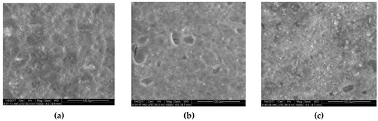
Figure 1.
Scanning electron microscope (SEM) images of (a) original cordierite, (b) cordierite (after pre-treatment), and (c) 7.5 wt % Mn/cordierite catalyst.
To determine the actual content of active components on the catalyst, three samples were tested by inductively coupled plasma optical emission spectroscopy (ICP-OES). Two parallel samples were tested, and the average value was taken as the test result (Table 2). It can be seen from Table 2 that the actual load of Mn was lower than that calculated theoretically, indicating that there was a certain amount of loss of active components during catalyst preparation.
Table 2.
Elemental analysis results for the catalysts.
2.2. Degradation of Toluene in DBD and DDBD Reactor
At a set energy level (250 J·L−1), the degradation of toluene was carried out and the performance of DBD and DDBD reactors was compared in terms of discharge and degradation efficiency. The flow direction conversion period was 8 min per cycle and the gas flow rate was 6 L·min−1. The five kinds of reactors tested were the: (I) DBD reactor; (II) DBD-catalyst reactor; (III) DDBD reactor; (IV) DDBD-catalyst reactor; and (V) reverse-flow DBD-catalyst reactor. Points P and Q are the temperature measurement points of the heat storage section of the reactor, and point O is at the discharge area in Figure 2a.
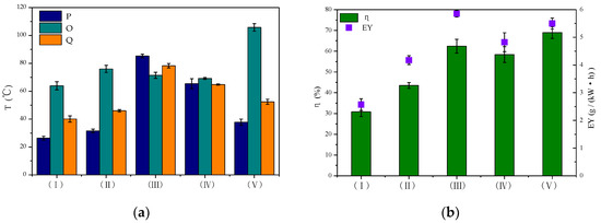
Figure 2.
Toluene degradation in different reactors. (a) Changes in T; (b) changes in η and energy yield (EY).
In the experiments, DDBD reactors were found to decrease the discharge energy density under the same discharge voltage compared with DBD reactors. This was due to the increase of the dielectric layer thickness in the tube and the decrease of the discharge space in the system, so the comparison was carried out under the same discharge energy density.
From Figure 2a, it can be seen that the temperature in the conventional DBD reactor (I) was low, while the temperature in the DDBD reactor (III) was relatively high. The difference between the three temperature measuring points in the latter reactor was small. The temperature of the DDBD reactor with an empty tube was relatively high, up to 85.3 °C. In the DDBD reactor, the airflow entered the outer tube after entering the buffer stable flow field. The change of air-flow direction in the inner and outer tubes led to a relatively consistent increase in the temperature of the system. Therefore, compared with the DBD reactor, the temperature of the DDBD reaction zone was higher.
Due to the existence of multiple dielectric layers in the DDBD reactors, the discharge of the inner tube was more intense, forming a strong electric field area as the outer tube formed a weak electric field area. With the same energy input, pollutants passed through the two discharge areas of the strong electric field in the inner tube and the weak electric field in the outer tube, so that the toluene conversion was improved by 31.6% (Figure 2b). However, compared with conventional DBD reactor, the distribution of strong and weak electric fields in DDBD reactors resulted in the formation of more organic by-products. The gas velocity was higher in the inner pipe, and the reaction time of pollutants passing through the strong electric field was shorter. As previously reported, short residence time decreases the removal efficiency of VOCs [36,37]. Some pollutant molecules were initially destroyed by collision with high-energy particles. However, due to the insufficient reaction time, some pollutant molecules left the strong discharge area before being completely degraded, leading to the formation of a large number of organic by-products that attached to the inner tube wall.
In the DDBD-catalyst reactor (IV), the surface of the catalyst was readily covered by organic by-products. This made it difficult for the catalyst to play its role as there was a synergistic effect between the catalyst and plasma only in the early stage of the reaction, which gradually weakened with the extension of discharge time. Therefore, the DDBD-catalyst reactor could not effectively improve the degradation efficiency of pollutants or the energy yield of the system.
For the DBD-catalyst reactor (II), Figure 2b shows that with increasing system temperature, the degradation rate of toluene increased by 12.7% and the energy field increased by 1.6 g·kW−1·h−1. This indicated that the introduction of a catalyst was beneficial to the purification of pollutants, showing a certain synergistic effect. On the catalyst surface, the adsorbed pollutants were degraded by high-energy electrons and active radicals. Meanwhile, ozone and other long-lived substances with oxidative ability were adsorbed on the catalyst surface, which also promoted the degradation of toluene. However, the degradation effect of pollutants still needed to be improved in the DDBD reactor.
Considering the serious secondary pollution caused by the generation of organic by-products in the DDBD reactor, the flow reversal technology was connected in series with the DBD reactor to enable change of flow direction and optimization of the reaction system. Most of the heat generated by the discharge of a single DBD reactor was carried out of the reactor by air flow. However, in the reverse-flow DBD-catalyst reactor (V), the heat generated by plasma discharge or released by catalytic oxidation further increased the system temperature. As shown in Figure 2a,b, the heat generated by the flow direction conversion technology oscillated back and forth in the system, achieving a maximum system temperature of 105.8 °C. This effectively activated the catalyst and improved the catalytic oxidation efficiency and energy yield (EY) of the system, achieving improvement by 38.1% and 2.93 g·kW−1·h−1.
In the process of catalytic degradation of toluene in the nonthermal plasma systems, the mixture of toluene was obtained by purging with air, so the formation of ozone was inevitable. Figure 3 shows that the concentration of ozone generated in the DDBD reactor was significantly higher than that in the DBD reactor. The concentration of ozone was lowest in the reverse-flow DBD-catalyst reactor, at 162.9 mg·m−3, as some of the ozone was decomposed in the later stage of the reaction. In the DDBD reactor, the concentration of O3 increased gradually with the extension of the discharge time, finally reaching 448.4 mg·m−3. At this time, part of the ozone participated in the reaction or thermal decomposition, resulting in a slightly decreased concentration. However, in the DDBD reactor, due to the weak field strength in the discharge area of the outer tube and the low-temperature increase of the system, the ozone concentration was much higher than that in the DBD reactor. When catalyst was added into the reactor, the formation of O3 was inhibited [38] and the concentration of O3 decreased. The catalyst could absorb ozone on its active sites to achieve catalytic degradation of ozone, effectively decreasing the concentration of O3 and ultimately decreasing secondary pollution [39].
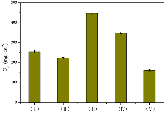
Figure 3.
Concentration of O3 formed in different reactors.
2.3. Toluene Degradation in Reverse-Flow DBD-Catalyst Reactor
In the reverse-flow DBD-catalyst reactor, toluene degradation experiments were carried out under different reaction system conditions. Furthermore, in order to study the role of flow reversing technology on the reverse-flow DBD-catalyst reactor, toluene degradation was investigated under different flow reversing parameters.
2.3.1. Effect of Flow Reversing Cycle Time
The flow reversing cycle is one of the most important factors affecting reactor performance. When the flow direction switches, the heat oscillates in the reactor [40] where it can heat the intake air and ensure the preheating of the catalyst bed [41]. The effect of the flow reversing cycle time on toluene degradation was investigated with a discharge voltage of 16 kV, frequency of 100 Hz, and residence time of 0.33 s. By selecting the appropriate commutation period, effective heat accumulation can be achieved [42].
Compared with the conventional DBD reactor, it was found that the central temperature of position O increased markedly after reversing the flow direction, resulting in more heat being stored in the reaction zone. From Figure 4 it can be seen that when the flow reversing cycle time was 8 min, the maximum temperature of the discharge area could reach 105.8 °C, which was about 50 °C above the temperature at both ends, and the discharge area temperature was 39.6 °C higher than when the flow reversing cycle time was 16 min. As the flow reversing cycle time was further increased, the flow was maintained in a single direction for a long time. This meant that the heat was easily carried out by the air flow, which was not conducive to the accumulation of heat and resulted in the gradual decline of overall temperature in the system and a large amount of wasted energy. This, in turn, weakened the role of the catalyst in the synergistic degradation of toluene.
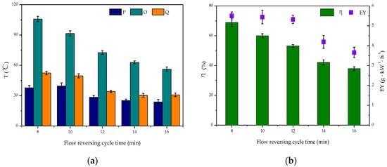
Figure 4.
Effect of flow reversing cycle on reverse-flow dielectric barrier discharge (DBD)-catalyst reactor capabilities: (a) changes in T; (b) changes in η and EY.
The degradation rate of toluene and the energy yield of the system were also negatively related to the reversing cycle time. With a 16 min cycle time, the degradation rate of toluene decreased by 31%, while the energy yield of the system decreased by 1.84 g·kW−1·h−1. Therefore, the extension of flow reversing cycle time resulted in increased release of heat generated in the plasma reactor and the rapid annihilation of high-energy electrons, which led to decreased toluene degradation rate and energy yield. Therefore, the optimal flow reversing cycle time was 8 min, which produced the system with the highest heat utilization rate and afforded the best toluene degradation effect.
The effect of the reversing cycle on ozone generation is shown in Figure 5. As the reaction system was equipped with the flow reversing technology, part of the heat generated by the plasma discharge was stored in the heat storage section [43]. Since the internal temperature of the reaction system could reach up to 100 °C, the ozone was decomposed by heat while participating in toluene degradation. The heat accumulation of the system was weakened with the extension of the reversing cycle time, resulting in increased ozone concentration.
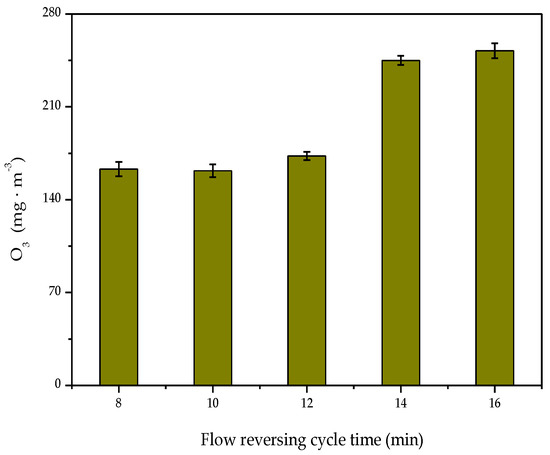
Figure 5.
Effect of flow reversing cycle time on O3 concentration.
2.3.2. Effect of Residence Time
Figure 6 shows the effects of air flow rate, and consequently, the residence time of toluene molecules, with a discharge voltage of 16 kV, frequency of 100 Hz, and flow reversing cycle time of 8 min. Due to the introduction of flow direction reversing technology, the continuous change in air flow direction resulted in part of the heat released by the discharge of the plasma reactor accumulating in the heat storage section. As the air flow increased, the residence time of toluene molecules in the reactor was shortened. The initial internal temperature of the system showed an overall upward trend. When the gas volume was 8 L·min−1, the temperature at point O was 48.2 °C, and the highest temperature was 105.8 °C. When the residence time was longer than 0.35 s, the toluene removal efficiency dropped sharply. The decrease in residence time increased the gas velocity. The high-speed gas drove the heat in the reactor to change the heat concentration point with the flow direction. When the residence time was longer than 0.33 s, the increase in gas volume resulted in an increase in the number of toluene molecules, improving the utilization ratio of active radicals and high-energy electrons. The system reacted violently and emitted more heat. When the residence time was shorter than 0.33 s, this resulted in increased gas velocity, which led to the aggregation point change and the temperature dropped sharply; when the residence time was too short, the collector moved out of the regenerator and caused a sharp decrease in system temperature and the disappearance of flow direction reversal. The effect was similar to that of the ordinary DBD reactor.
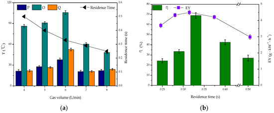
Figure 6.
Effect of the residence time on DBD reactor: (a) changes in T; (b) changes in η and EY.
As shown in Figure 6b, the degradation rate of toluene, the energy yield, and the temperature of the system firstly increased and then decreased with increased residence time. When the residence time was shortened, the reaction time of toluene molecules was shortened, and the degradation rate of toluene decreased by 35%. The EY decreased by 0.15 g·kW−1·h−1, which was lower than in the DDBD reactor.
As shown in Figure 7, the maximum concentration of ozone increased gradually as the residence time increased. As the maximum temperature in the reaction system could reach above 100 °C, the ozone participated in toluene degradation and was decomposed by the heat [44]. As the residence time increased, there were more reactions between pollutant molecules and active radicals in the reactor. At the same time, more active oxygen atoms reacted with each other to form ozone, but the increase of ozone generation was slow.
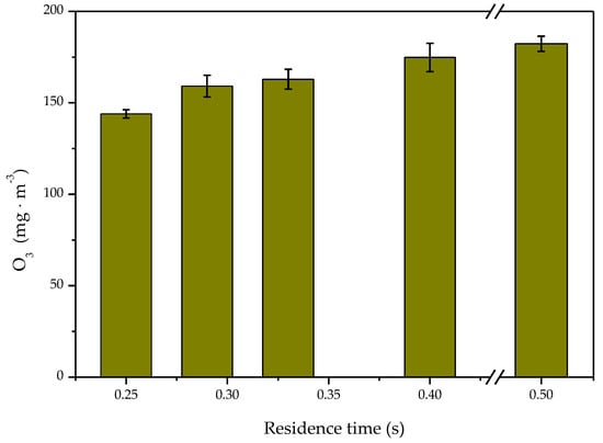
Figure 7.
Effect of the residence time on O3 concentration.
2.4. Gas-Phase Product Analysis
The degradation of VOCs by nonthermal plasma is a complex reaction process that is difficult to control, so the generation of intermediate by-products is inevitable. In order to investigate the effect of flow reversing on toluene degradation, the by-products generated in the reverse-flow DBD-catalyst reactor were investigated.
2.4.1. CO2
In the degradation of toluene, the amount of CO2 produced reflects the degree of toluene degradation. The CO2 selectivity in the process of toluene degradation by DBD and DDBD reactors was compared, with the results shown in Figure 8.
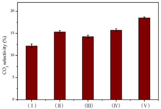
Figure 8.
CO2 selectivity in different reactors.
Under the same discharge energy density, CO2 selectivity was the highest when toluene was degraded by flow reversing plasma catalysis. Due to the relatively low degradation rate of toluene in the DBD reactor (I), the CO2 selectivity was also poor at only 12%. Additionally, the CO2 selectivity in the DDBD reactor (III) was not as good as that in the reverse-flow DBD-catalyst reactor (V) due to the formation of more organic by-products. These results were consistent with the degradation of toluene under different reaction conditions.
2.4.2. NO2
Since the process of plasma degradation of VOCs is very dependent on the input of energy, higher energy input can increase the degradation rate of VOCs, but more NO2 will be formed at the same time. In the process of plasma treatment with air as the carrier gas, it is inevitable that nitrogen oxides will be generated. The NO2 concentration in the gas was detected using a flue gas analyzer. The generation conditions for different reactor types were compared, as shown in Figure 9.
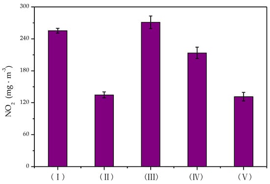
Figure 9.
Concentration of NO2 formed in different reactors.
It can be seen from Figure 9 that less NO2 was generated in the DBD reactor (I) than in the DDBD reactor (III). In the DBD reactor, the amount of NO2 production decreased significantly from 255.2 mg·m−3 to 134.7 mg·m−3 after the introduction of the catalyst. When also combined with flow reversing, the amount of NO2 production further decreased by 3.28 mg·m−3. In the DDBD reactor, the amount of NO2 production decreased by 68.5 mg·m−3 after the addition of the catalyst, so it could be inferred that the formation and degradation of NO2 were mainly related to the presence of the catalyst. There was no obvious effect of heat accumulation by the introduction of flow reversing technology.
2.4.3. Organic By-Products
In the study, infrared analysis and gas chromatography-mass spectroscopy (GC-MS) were used to detect the types of organic by-products generated in the exhaust gas under different reaction conditions. According to the different vibration frequencies in the infrared spectrum, the gas-phase product categories were determined.
As shown in Figure 10 and Table 3, ketones, acids, alcohols, and esters were the main organic by-products generated during toluene degradation. DBD reactor (I) and DDBD reactor (III) produced a greater concentration and more different types of by-products, and there were more polymer by-products. After the addition of the catalyst to the system, the types of by-products decreased in reactors (II) and (IV). After the addition of catalyst and flow reversing the system, the amount of by-products produced in reactor (V) was significantly decreased and there were less types of by-products; mainly ketones and alcohols were produced. This indicated that the optimized system was conducive to the degradation of toluene and decreased the generation of organic by-products, thereby decreasing secondary pollution.
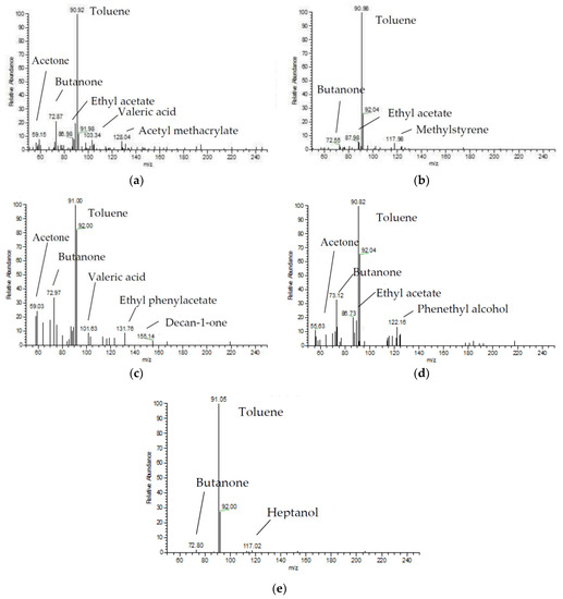
Figure 10.
Gas chromatography-mass spectroscopy (GC-MS) results from different reactors. (a) DBD reactor; (b) DBD-catalyst reactor; (c) DDBD reactor; (d) DDBD-catalyst reactor; (e) Reverse-flow DBD-catalyst reactor.
Table 3.
Main products in different reactors. DBD, dielectric barrier discharge; DDBD, double dielectric barrier discharge.
Compared with the DBD reaction system, there were more by-products in the DDBD reaction system, and the transformation of toluene was highly incomplete. The generation of organic by-products was not significantly improved in the process of collaborative catalysis, and the degradation of pollutants and CO2 selectivity were not good. It was suspected that the active sites on the catalyst surface were covered by a large number of organic by-products, leading to deactivation of the catalyst and even further blocking of the catalyst pores, resulting in poor degradation of pollutants and more by-product generation. The experimental results showed that the least amount and types of organic by-products were produced in the flow reversing DBD catalyst reactor, with this system most effectively inhibiting by-product generation of all the reactors tested.
2.5. Reaction Mechanism
The reaction process of nonthermal plasma co-catalysis for VOC degradation is complex, and the reaction mechanism has not been completely elucidated. Nonthermal plasma plays an important role in the actual reaction process. Applying knowledge of the reaction mechanism to this study, electrons collided with toluene gas and with other particles, inelastically, to transfer most of their kinetic energy to the particles. This changed the state or structure of the particles, thus producing a large number of excited active radicals [45]:
e + O2 → 2 O• + e
e + H2O → OH• + H• + e
e + N2 → 2 N• + e
The toluene molecules were destroyed by the attack of high-energy electrons and gas-phase radicals (such as O• and OH•) [12,46]. Therefore, in this experiment, aluminum foil as the grounding electrode produced a uniform and dense electric field, high-energy electrons, and active radicals, which effectively promoted the degradation of toluene. Due to the low bond energy of both the C–H bonds of the methyl group attached to the benzene ring, and the C–C bond between the benzene ring and methyl group (C–H bond: 3.5 eV; C–C bond: 3.8 eV), the attack of high-energy electrons and active radicals broke these C–H and C–C bonds, thus forming benzene ring derivatives and other organic intermediates. Benzoic acid, phenylacetic acid, phenylacetone, and other substances were obtained from the product analysis results. As the carbon atoms of the benzene ring were bonded in a conjugated π-bond, the benzene ring structure was relatively stable [47]. However, under the double attack of active radicals and high-energy electrons, the benzene ring was broken. After ring opening, ether, acid, ketone, and other by-products were further generated, such as acetone, ethyl acetate, and so on. At the same time, some of the intermediate products reacted further to form more complex structures.
In nonthermal co-catalysis, the plasma and the catalyst acted on the gas component by producing plasma chemical reactions and lowering the surface barrier of the catalyst, respectively. Plasma-activated gas molecules formed free radicals and influenced the catalytic process. The physicochemical properties of the catalyst, such as roughness and dielectric constant, affected the electric field distribution near the catalyst, thus affecting the rate of the gas-phase process [48,49]. Thus, the plasma and the catalyst had a synergistic effect [13].
The combination of plasma and catalyst mainly affected the degradation efficiency, energy yield, and types of pollutants formed. After the catalyst was added to the system, the form of discharge changed to a combination of surface discharge of the catalyst and weak micro-discharge in the gap space [50], resulting in decreased toluene conversion efficiency. Only when the generated surface discharge could increase the activity of the catalyst could its negative impact be compensated for by catalytic action [51]. This also explained why there was direct impact on the degradation of pollutants in the DDBD catalytic reactor when the catalyst surface became coated, resulting in its inactivation.
In this experiment, the introduction of manganese catalyst resulted in O3, O2, high-energy electrons, and active radicals in the gas adsorbing onto the catalyst surface. In the process of catalytic degradation of toluene by nonthermal plasma, high-energy electrons reacted with oxygen in the exhaust gas to form oxygen radicals, and then ozone. As the electron affinity of O3 (2.1 eV) is much higher than that of O2 (0.44 eV), O3 can be used as an electron acceptor to promote the formation of highly oxidized oxygen atoms [52]. Therefore, O3 was not only a by-product, but also a strong oxidant, which played an important role in the destruction of toluene.
Among the various kinds of active radicals produced, oxygen radicals (O•) and hydroxyl radicals (OH•) had the strongest oxidative ability. In the reaction process, these could react directly with toluene molecules and intermediate products adsorbed on the catalyst surface [53]. The role of ozone in the catalytic oxidation process was mainly as an electron acceptor, producing more hydroxyl radicals and decreasing the recombination rate of electron-hole pairs, thus accelerating the formation of hydroxyl radicals.
With the continuous function of radicals, benzene rings were further decarburized to form straight-chain organic intermediates, and ultimately CO2 and H2O were produced. The reaction rate of the catalyst surface depended on the chemical adsorption of toluene, the type of chemisorbed oxygen, Mn–O bond strength, and the conversion rate between different valence manganese oxides [48,50]. Manganese-based catalysts can decompose active O3 [54,55]. In this study, the catalyst adsorbed O3 at its active sites, decomposed it into O• and O2, part of which reacted with adsorbed oxygen species and the other part oxidized toluene or organic by-products, as follows [47,52]:
X*+ O3 → X + O* + O2
O3 + O* → 2 O2 + *
Here, X and * stand for catalysts and active sites, respectively.
Nonthermal plasma can induce the dielectric heating of the catalyst, thereby improving its apparent catalytic activity [10]. Additionally, the combination of flow reversing increased the system temperature, further increasing catalyst activity. The mechanism of toluene degradation by the DDBD-catalyst reactor was consistent with that of the DBD-catalyst reactor. The key factor in the reaction was the generation of various active substances, such as high-energy electrons, hydroxyl radicals, and oxygen radicals [56]. According to the above results and discussion, the total reaction mechanism for toluene degradation by non-thermal plasma co-catalysis technology is shown in Figure 11 [51].
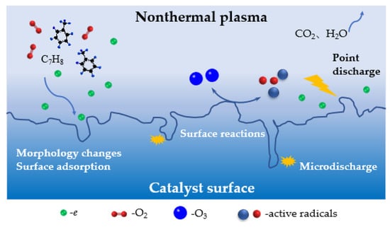
Figure 11.
Reaction mechanism for toluene degradation by nonthermal plasma co-catalysts.
3. Experimental
3.1. Reaction Process
The reaction device is shown in Figure 12. The DBD and DDBD reactor outer tubes were quartz glass tubes 32 mm in diameter and 1.5 mm in wall thickness. The DDBD reactor inner tubes were 8 mm in diameter and had 1 mm wall thickness. An aluminum foil-wound reaction tube was used as the grounding electrode, with an effective discharge length of 50 mm. A tungsten wire was used as the high voltage electrode through the center of the reaction tube, with a diameter of 1.5 mm. The outside of the reactor was wrapped with insulating cotton. In the experiment, an alternating current (AC) power supply with variable frequency and variable voltage was used; frequency regulating range was 50–3000 Hz and the voltage regulating range was 0–100 kV. The discharge duration was 2 h. Three test positions were chosen to monitor the temperature at different positions in the reactor: O, in the middle in the discharge area; P and Q, in the middle of the heat storage section.
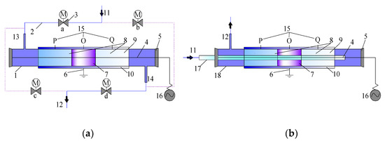
Figure 12.
(a) DBD reactor and (b) DDBD reactor. Schematic diagram of reaction device: 1. quartz tube; 2. gas pipeline; 3. solenoid valve; 4. high voltage; 5. insulating plug; 6. grounding pole; 7. discharge area (catalyst section); 8. heat storage section; 9. regenerator; 10. insulating cotton; 11. main air inlet; 12. main air outlet; 13. reactor inlet (outlet); 14. reactor outlet (inlet); 15. thermocouple temperature measuring position; 16. power supply; 17. inner tube of DDBD reactor; 18. outer tube of DDBD reactor.
3.2. Flow-Reversal Device
As shown in Figure 12a, the flow-reversal device controlled the opening and closing of the pipeline through the solenoid valve. When only solenoid valves ‘a’ and ‘d’ were opened, the gas passed through the reactor from left to right; when only the solenoid valves ‘c’ and ‘b’ were opened, the gas passed through the reactor from right to left. In this way, the flow direction of the gas was controlled. Five kinds of reactors were involved in the experiment.
3.3. Filling Materials
The filling materials in the reactor included regenerator and catalyst. The regenerator used in the experiment was cordierite honeycomb ceramic (400 mesh, Φ29 mm, d = 12.5 mm). The catalyst was 7.5 wt % Mn/cordierite, which was placed in the discharge area with a bed length of 50 mm.
3.3.1. Catalyst Preparation
The 7.5 wt % Mn/cordierite catalyst was prepared using the impregnation method with cordierite honeycomb ceramic of the same specification as the support. The specific preparation process was as follows. After the cut cordierite carrier was cleaned with oxalic acid and deionized water, the surface was coated with silica sol and dried. Certain amounts of manganese nitrate solution and γ-Al2O3 powder were mixed evenly in deionized water by stirring for 3 h in a water bath at 60 °C to obtain the precursor slurry. After ultrasonic stirring at 60 °C for 6 h, the catalyst was prepared by dipping the carrier in the slurry and baking it at 110 °C for 2 h, then calcining in a muffle furnace at 180 °C for 1 h and at 500 °C for 3 h.
3.3.2. Catalyst Characterization
The specific surface area, pore volume, and pore size of the samples were determined using a specific surface analyzer (Gemini V, Micromeritics, Norcross, GA, USA) by the Brunauer-Emmett-Teller (BET) method and the Barret-Joyner-Halenda (BJH) method. Scanning electron microscopy (SEM) was performed using the S-4300 microscope (Hitachi, Tokyo, Japan). ICP-OES analysis was performed using an atomic emission spectrometer (IRIS Intrepid ER/S, Thermo, Waltham, MA, USA).
3.4. Testing Methods
A saturated stream of pure toluene solution in a constant temperature water bath was swept by air prior to entering the gas mixing cylinder. The air passed through the drying pipe in advance of entering. The mixed gas entered the flow direction changing device after adjustment by the mass flowmeter. The toluene concentration was maintained at 600 mg·m−3.
Toluene concentration was determined by gas chromatography (GC; 6890 N, Agilent, Palo Alto, CA, USA), and ozone content was monitored by an ozone analyzer (106-M, 2B Technology, Boulder, CO, USA). The formation of gaseous products such as CO2 and NO2 was detected by a flue gas analyzer (Testo 350M, Lenzkirch, Germany), and the organic by-products of the reaction were determined by infrared spectrometry (Nicolet iS5, Thermo, Waltham, MA, USA) and gas chromatography-mass spectroscopy (GC-MS; Trace DSQ, Thermo, Waltham, MA, USA).
The main parameters involved in the experiment were as follows. According to the concentration of toluene determined by GC, η was used to indicate toluene conversion, %. Specific energy density (SED) was used to express the discharge energy density of injected unit reaction gas, J·L−1. Energy yield (EY) was used to express the amount of pollutants removed per unit energy consumption, g·kW−1·h−1. The calculation formulas are detailed in the literature [34], and are as follows:
Here, C1 and C2 represent the concentration value of toluene import and export, respectively, mg·m−3; F is the gas flow rate, L·min−1; Umax is he voltage peak value, kV; and I is the secondary current value, mA.
4. Conclusions
In order to make full use of the heat in nonthermal plasma systems and decrease the generation of by-products, a reverse-flow nonthermal plasma reactor coupled with catalysts was used for the abatement of toluene. With extension of the commutation period and shortening of the residence time, the system temperature gradually decreased, which was not conducive to the degradation of toluene. Therefore, it was necessary to select appropriate flow direction conversion conditions to make full use of the heat. Under DDBD reaction conditions, the degradation efficiency of toluene was higher than under DBD, but the concentration of NO2 and ozone was relatively high. The selectivity of NO2 generated in the DBD reactor was lower, and there was decreased NO2 generation in the DBD reactor after the introduction of flow direction conversion. When catalyst was added, the concentrations of NO2 and ozone decreased markedly. The organic by-products in the tail gas mainly included aromatics, acids, and ketones. In the reverse-flow nonthermal plasma reactor coupled with catalysts, the selectivity for CO2 was the highest, and the selectivity and amount of NO2 were the lowest.
Author Contributions
Conceptualization, W.L.; methodology, W.L. and H.S.; validation, W.L. and H.S.; formal analysis, W.L., H.S. and X.S.; data curation, H.S., X.S. and Y.Z.; writing—original draft preparation, H.S.; writing—review and editing, W.L.; supervision, W.L.; project administration, W.L.; funding acquisition, W.L. All authors have read and agree to the published version of the manuscript.
Funding
This research was funded by The National Key Research and Development Program of China, grant number 2018YFC1903105 and Beijing Major Science and Technology Projects, grant number Z191100009119002.
Conflicts of Interest
The authors declare no conflicts of interest.
References
- Mizuno, A. Generation of non-thermal plasma combined with catalysts and their application in environmental technology. Catal. Today 2013, 211, 2–8. [Google Scholar] [CrossRef]
- Lu, W.J.; Abbas, Y.; Mustafa, M.F.; Pan, C.; Wang, H. A review on application of dielectric barrier discharge plasma technology on the abatement of volatile organic compounds. Front. Environ. Sci. Eng. 2019, 13, 30. [Google Scholar]
- Zhang, H.; Ying, D.; Wang, Y.; Sun, T.; Jia, J. In plasma catalytic oxidation of toluene using monolith CuO foam as a catalyst in a wedged high voltage electrode dielectric barrier discharge reactor: Influence of reaction parameters and byproduct control. Int. J. Environ. Res. Public Health 2019, 16, 711. [Google Scholar]
- Wang, B.F.; Xu, X.X.; Xu, W.C.; Wang, N.; Xiao, H.L.; Sun, Y.H.; Hang, X.M.; Yu, L.; Fu, M.L.; Wu, J.L.; et al. The mechanism of non-thermal plasma catalysis on volatile organic compounds removal. Catal. Surv. Asia 2018, 22, 73–94. [Google Scholar]
- Preis, S.; Klauson, D.; Gregor, A. Potential of electric discharge plasma methods in abatement of volatile organic compounds originating from the food industry. J. Environ. Manag. 2013, 114, 125–138. [Google Scholar] [CrossRef]
- Brandenburg, R. Dielectric barrier discharges: Progress on plasma sources and on the understanding of regimes and single filaments. Plasma Sources Sci. Technol. 2017, 26, 053001. [Google Scholar] [CrossRef]
- Nitsche, T.; Unger, C.; Weidner, E. Plasma catalytical reactors for atmospheric gas conversions. Chem. Ing. Tech. 2018, 90, 1453–1464. [Google Scholar] [CrossRef]
- Neyts, E.C.; Ostrikov, K.; Sunkara, M.K.; Bogaerts, A. Plasma catalysis: Synergistic effects at the nanoscale. Chem. Rev. 2015, 115, 767. [Google Scholar] [CrossRef]
- Shi, Y.; Shao, Z.; Shou, T.; Tian, R.; Jiang, J.; He, Y. Abatement of gaseous xylene using double dielectric barrier discharge plasma with in situ UV light: Operating parameters and byproduct analysis. Plasma Chem. Plasma Process. 2016, 36, 1501–1515. [Google Scholar] [CrossRef]
- Zhou, W.; Guan, Z.; Zhao, M.; Li, J. Characteristics and mechanism of toluene removal from gas by novelty array double dielectric barrier discharge combined with TiO2/Al2O3 catalyst. Chemosphere 2019, 226, 766–773. [Google Scholar] [CrossRef]
- Tang, X.L.; Gao, F.Y.; Wang, J.G.; Yi, H.H.; Zhao, S.Z.; Zhan, B.W.; Zuo, Y.R.; Wang, Z.X. Comparative study between single- and double-dielectric barrier discharge reactor for nitric oxide removal. Ind. Eng. Chem. Res. 2014, 53, 6197–6203. [Google Scholar] [CrossRef]
- Li, S.J.; Yu, X.; Dang, X.Q.; Guo, H.; Liu, P.; Qin, C.H. Using non-thermal plasma for decomposition of toluene adsorbed on γ-Al2O3 and ZSM-5: Configuration and optimization of a double dielectric barrier discharge reactor. Chem. Eng. J. 2019, 375, 122027. [Google Scholar] [CrossRef]
- Zhang, H.B.; Li, K.; Shu, C.H.; Lou, Z.Y.; Sun, T.H.; Jia, J.P. Enhancement of styrene removal using a novel double-tube dielectric barrier discharge (DDBD) reactor. Chem. Eng. J. 2014, 256, 107–118. [Google Scholar] [CrossRef]
- Mustafa, M.F.; Fu, X.; Liu, Y.; Abbas, Y.; Wang, H.; Lu, W. Volatile organic compounds (VOCs) removal in non-thermal plasma double dielectric barrier discharge reactor. J. Hazard. Mater. 2018, 347, 317–324. [Google Scholar] [CrossRef] [PubMed]
- Muhammad, N.; Eko, Y.; Andi, W.K. Development of DDBD and plasma jet reactors for production reactive species plasma chemistry. IOP Conf. Ser. Mater. Sci. Eng. 2019, 509, 012086. [Google Scholar]
- Qin, C.H.; Dang, X.Q.; Huang, J.Y.; Teng, J.; Huang, X.M. Plasma-catalytic oxidation of adsorbed toluene on Ag–Mn/γ-Al2O3: Comparison of gas flow-through and gas circulation treatment. Chem. Eng. J. 2016, 299, 85–92. [Google Scholar] [CrossRef]
- Zhu, X.B.; Gao, X.; Yu, X.N.; Zheng, C.H.; Tu, X. Catalyst screening for acetone removal in a single-stage plasma-catalysis system. Catal. Today 2015, 256, 108–114. [Google Scholar] [CrossRef]
- Jiang, N.; Hu, J.; Li, J. Plasma-catalytic degradation of benzene over Ag–Ce bimetallic oxide catalysts using hybrid surface/packed-bed discharge plasmas. Appl. Catal. B 2016, 184, 355. [Google Scholar] [CrossRef]
- Zhu, X.B.; Gao, X.; Qin, R.; Zeng, Y.X.; Qu, R.Y.; Zheng, C.H.; Tu, X. Plasma-catalytic removal of formaldehyde over Cu–Ce catalysts in a dielectric barrier discharge reactor. Appl. Catal. B 2015, 293, 170–171. [Google Scholar] [CrossRef]
- Vandenbroucke, A.M.; Morent, R.; Geyter, N.D.; Leys, C. Non-thermal plasmas for non-catalytic and catalytic VOC abatement. Hazard. Mater. 2011, 195, 30–54. [Google Scholar] [CrossRef]
- Liang, W.J.; Guo, S.Q.; Ren, S.D.; Li, Q.L.; Li, J. Decompositon of toluene using non-thermal plasma coupled with Mn-Ce/La/cordierite honeycomb catalysts. Fresenius Environ. Bull. 2020, 29, 473–480. [Google Scholar]
- Kim, H.H.; Teramoto, Y.; Negishi, N.; Ogata, A.A. multidisciplinary approach to understand the interactions of nonthermal plasma and catalyst: A review. Catal. Today 2015, 256, 13–22. [Google Scholar] [CrossRef]
- Savita, V.; Christophe, L.; Nathalie, D.G.; Rino, M. Abatement of VOCs using packed bed non-thermal plasma reactors: A review. Catalysts 2017, 7, 113. [Google Scholar]
- Siddharth, G.; Gu, S. Influence of catalyst packing configuration on the discharge characteristics of dielectric barrier discharge reactors: A numerical investigation. Phys. Plasmas 2015, 25, 063513. [Google Scholar]
- Nader, R.; Shayan, H.; Somaiyeh, A. Application of plasma technology in the removal of volatile organic compounds (BTX) using manganese oxide nano-catalysts synthesized from spent batteries. J. Clean. Prod. 2019, 232, 1134–1147. [Google Scholar]
- Zhu, B.; Zhang, L.Y.; Li, M.; Yan, Y. High-performance of plasma-catalysis hybrid system for toluene removal in air using supported Au nano-catalysts. Chem. Eng. J. 2020, 381, 122599. [Google Scholar] [CrossRef]
- Christopher, W.J. Plasma-catalysis: Is it just a question of scale. Chem. Sci. Eng. 2019, 13, 264–273. [Google Scholar]
- Hu, J.; Jiang, N.; Li, J.; Shang, K.; Lu, N.; Wu, Y. Degradation of benzene by bipolar pulsed series surface/packed-bed discharge reactor over MnO2–TiO2/zeolite catalyst. Chem. Eng. J. 2016, 293, 216–224. [Google Scholar] [CrossRef]
- Zhu, Y.Y.; Chen, G.; Li, X.B. Resonance response of reverse flow reactors: A numerical simulation. Ind. Eng. Chem. Res. 2015, 54, 5885–5893. [Google Scholar] [CrossRef]
- Qin, Z.F.; Zhao, Y.J.; Yi, Q. Methanation of coke oven gas over Ni-Ce/γ-Al2O3 catalyst using a tubular heat exchange reactor: Pilot-scale test and process optimization. Energy Convers. Manag. 2020, 204, 112302. [Google Scholar] [CrossRef]
- Edouard, D.; Hammouri, H.; Zhou, X.G. Control of a reverse flow reactor for VOC combustion. Chem. Eng. Sci. 2005, 60, 1661–1672. [Google Scholar] [CrossRef]
- Krzysztof, G.; Anna, P.K. Aerodynamic CFD simulations of experimental and industrial thermal flow reversal reactors. Chem. Eng. J. 2019, 373, 1367–1379. [Google Scholar]
- Liang, W.J.; Liu, H.; Li, J. Ventilation air methane combustion in a flow reversal catalyst reactor effect sf catalyst, reactor properties and humidity. Fresenius Environ. Bull. 2017, 26, 2302–2313. [Google Scholar]
- Liang, W.J.; Sun, H.P.; Zhu, Y.X.; Li, J. Removal of toluene with a reverse flow non-thermal plasma-catalytic reaction system. China Environ. Sci. 2019, 39, 4974–4981. (In Chinese) [Google Scholar]
- Liang, W.J.; Wu, H.M.; Li, J. Removal of VOCs and heat distribution in a flow reversal plasma reaction system. J. Environ. Eng. Technol. 2018, 8, 373–380. (In Chinese) [Google Scholar]
- Asilevi, P.J.; Yi, C.W.; Li, J. Decomposition of formaldehyde in strong ionization non-thermal plasma at atmospheric pressure. Int. J. Environ. Sci. Technol. 2020, 17, 765–776. [Google Scholar] [CrossRef]
- Faisal, S.; Zhang, K.; Adam, P.H. Decomposition of benzene as a tar analogue in CO2 and H2 carrier gases, using a non-thermal plasma. Chem. Eng. J. 2019, 360, 714–720. [Google Scholar]
- Chen, X.; Zhao, Z.L.; Liu, S.; Huang, J.X.; Xie, J.; Zhou, Y.; Pan, Z.Y.; Lu, H.F. Ce-Fe-Mn ternary mixed-oxide catalysts for catalytic decomposition of ozone at ambient temperatures. J. Rare Earths 2020, 38, 175–181. [Google Scholar] [CrossRef]
- Kwon, D.W.; Kim, G.J.; Won, J.M.; Hong, S.C. Influence of Mn valence state and characteristic of TiO2 on the performance of Mn-Ti catalysts in ozone decomposition. Environ. Technol. 2017, 38, 2785–2792. [Google Scholar] [CrossRef]
- Pablo, M.; Salvador, O.; Fernando, V.D. Procedures for heat recovery in the catalytic combustion of lean methane—Air mixtures in a reverse flow reactor. Chem. Eng. J. 2009, 147, 356–365. [Google Scholar]
- Zhang, J.J.; Lei, Z.G.; Li, J.W. Simulation of a reverse flow reactor for the catalytic combustion of lean methane emissions. Chin. J. Chem. Eng. Engl. Edit. 2014, 22, 843–853. [Google Scholar] [CrossRef]
- Li, Z.K.; Wu, Z.W.; Qin, Z.F.; Zhu, H.Q.; Wu, J.B.; Wang, R.Y.; Lei, L.J.; Chen, J.G.; Dong, M.; Fan, W.B.; et al. Demonstration of mitigation and utilization of ventilation air methane in a pilot scale catalytic reverse flow reactor. Fuel Process. Technol. 2017, 160, 102–108. [Google Scholar] [CrossRef]
- Ershov, B.G.; Panich, N.M. The solubility and decomposition of ozone in solutions of sulfuric and perchloric acids in the temperature range from 25 to −70 °C. Dokl. Phys. Chem. 2015, 465, 279–282. [Google Scholar] [CrossRef]
- Chang, C.L.; Lin, Y.C.; Bai, H.L. Applying spray pyrolysis to synthesize MnOx for decomposing isopropyl alcohol in ozone- and thermal-catalytic oxidation. Korean J. Chem. Eng. 2009, 26, 1047–1052. [Google Scholar] [CrossRef]
- Zhao, X.L.; Liu, X.; Liu, J.Q. The effect of ionization energy and hydrogen weight fraction on the non-thermal plasma volatile organic compounds removal efficiency. J. Phys. D Appl. Phys. 2019, 52, 145201. [Google Scholar] [CrossRef]
- Penetrantey, B.M.; Hsiaoy, M.C.; Bardsleyy, J.N.; Merritty, B.T.; Vogtliny, G.E.; Kuthiz, A.; Burkhartz, C.P.; Baylessz, J.R. Identification of mechanisms for decomposition of air pollutants by non-thermal plasma processing. Plasma Sources Sci. Technol. 1997, 6, 251–259. [Google Scholar] [CrossRef]
- Huang, H.B.; Ye, D.Q.; Dennis, Y.C.L.; Feng, F.D.; Guan, X.J. By products and pathways of toluene destruction via plasma-catalysis. J. Mol. Catal. A Chem. 2011, 336, 87–93. [Google Scholar] [CrossRef]
- Wang, T.; Chen, S.; Wang, H.Q.; Liu, Z.; Wu, Z. In-plasma catalytic degradation of toluene over different MnO2 polymorphs and study of reaction mechanism. Chin. J. Catal. Engl. Edit. 2017, 38, 793–804. [Google Scholar] [CrossRef]
- Erik, C.N. Atomistic simulations of plasma catalytic processes. Front. Chem. Sci. Eng. 2018, 12, 145–154. [Google Scholar]
- Liu, L.; Zheng, C.H.; Wu, S.H.; Gao, X.; Ni, M.; Cen, K. Manganese-cerium oxide catalysts prepared by non-thermal plasma for NO oxidation: Effect of O2 in discharge atmosphere. Appl. Surf. Sci. 2017, 416, 78–85. [Google Scholar] [CrossRef]
- Neyts, E.C.; Bogaerts, A. Understanding plasma catalysis through modelling and simulation—A review. J. Phys. D Appl. Phys. 2014, 47, 224010. [Google Scholar] [CrossRef]
- Ye, H.L.; Liu, Y.Q.; Chen, S.; Wang, H.Q.; Liu, Z.; Wu, Z.B. Synergetic effect between non-thermal plasma and photocatalytic oxidation on the degradation of gas-phase toluene: Role of ozone. Chin. J. Catal. Engl. Edit. 2019, 40, 681–690. [Google Scholar] [CrossRef]
- Alexander, P.; Wilfred, F.L.M.H.; Bert, E.J.M.V.H. Temperature-programmed plasma surface reaction: An approach to determine plasma-catalytic performance. Appl. Catal. B Environ. 2018, 239, 168–177. [Google Scholar]
- Wang, M.X.; Zhang, P.Y.; Li, J.G.; Jiang, C.J. The effects of Mn loading on the structure and ozone decomposition activity of MnOx supported on activated carbon. Chin. J. Catal. 2014, 35, 335–341. [Google Scholar] [CrossRef]
- Rezaei, E.; Soltan, J.; Chen, N. Catalytic oxidation of toluene by ozone over alumina supported manganese oxides: Effect of catalyst loading. Appl. Catal. B Environ. 2013, 136, 239–247. [Google Scholar] [CrossRef]
- Wala, A.S.; Aymen, A.A.; Monia, G.; Adbelkrim, B.; Wael, A.; Abdelmottaleb, O.; Isabelle, S.; Dominique, W.; Sami, R. Study of synergetic effect, catalytic poisoning and regeneration using dielectric barrier discharge and photocatalysis in a continuous reactor: Abatement of pollutants in air mixture system. Appl. Catal. B 2017, 213, 53–61. [Google Scholar]
© 2020 by the authors. Licensee MDPI, Basel, Switzerland. This article is an open access article distributed under the terms and conditions of the Creative Commons Attribution (CC BY) license (http://creativecommons.org/licenses/by/4.0/).