Article

Hydrogenation and Dehydrogenation of Tetralin and Naphthalene to Explore Heavy Oil Upgrading Using NiMo/Al2O3 and CoMo/Al2O3 Catalysts Heated with Steel Balls via Induction

1
School of Chemical Engineering, University of Birmingham, Edgbaston, Birmingham B15 2TT, UK
2
Faculty of Engineering, University of Nottingham, Nottingham NG7 2RD, UK
*
Authors to whom correspondence should be addressed.
Catalysts 2020, 10(5), 497; https://doi.org/10.3390/catal10050497
Submission received: 9 April 2020 / Revised: 21 April 2020 / Accepted: 28 April 2020 / Published: 1 May 2020

Abstract

:
This paper reports the hydrogenation and dehydrogenation of tetralin and naphthalene as model reactions that mimic polyaromatic compounds found in heavy oil. The focus is to explore complex heavy oil upgrading using NiMo/Al2O3 and CoMo/Al2O3 catalysts heated inductively with 3 mm steel balls. The application is to augment and create uniform temperature in the vicinity of the CAtalytic upgrading PRocess In-situ (CAPRI) combined with the Toe-to-Heel Air Injection (THAI) process. The effect of temperature in the range of 210–380 °C and flowrate of 1–3 mL/min were studied at catalyst/steel balls 70% (v/v), pressure 18 bar, and gas flowrate 200 mL/min (H2 or N2). The fixed bed kinetics data were described with a first-order rate equation and an assumed plug flow model. It was found that Ni metal showed higher hydrogenation/dehydrogenation functionality than Co. As the reaction temperature increased from 210 to 300 °C, naphthalene hydrogenation increased, while further temperature increases to 380 °C caused a decrease. The apparent activation energy achieved for naphthalene hydrogenation was 16.3 kJ/mol. The rate of naphthalene hydrogenation was faster than tetralin with the rate constant in the ratio of 1:2.5 (tetralin/naphthalene). It was demonstrated that an inductively heated mixed catalytic bed had a smaller temperature gradient between the catalyst and the surrounding fluid than the conventional heated one. This favored endothermic tetralin dehydrogenation rather than exothermic naphthalene hydrogenation. It was also found that tetralin dehydrogenation produced six times more coke and caused more catalyst pore plugging than naphthalene hydrogenation. Hence, hydrogen addition enhanced the desorption of products from the catalyst surface and reduced coke formation.

Graphical Abstract

1. Introduction

The possibility of generating thermal energy inside the reactor has been a subject of research in the field of catalysis. In this perspective, electromagnetic energy has been converted into heat by a composite catalyst material comprising of a conducting susceptor and a catalytic agent [1,2], or a mixed bed of catalyst and a conducting but chemically inert susceptor [3]. The electromagnetic energy can be supplied through an inductive, ohmic, or microwave system, and the heat generated inside the catalytic bed itself due to the susceptible component to the electromagnetic energy. This method of heating the catalytic bed holds several advantages over conventional heating using a furnace as it can be applied to target specific areas, minimizes heat loss to the surroundings, shortens heating and cooling times, allows better controllability, and can potentially lower both energy consumption and cost [3,4]. In contrast, the traditional heating method with a furnace suffers from heat transfer limitations. Consequently, it is necessary to investigate whether the presence of the electromagnetic field is beneficial to the catalyst performance, mass transport and the chemistry of the reaction.
The world has consumed about 1.31 trillion barrels of oil from 1969 to 2018, with a 2016 daily consumption rate of approximately 100 million barrels per day (BPD) according to the Energy Information Administration, EIA [5]. Currently, the top three consumers are the USA (20%), China (13%), and India (5%), and according to the EIA, the world daily demand is projected to increase by 1.4 million BPD in 2020 [5]. With the declining reserves of light oil, attention has been shifted to heavy oil and bitumen, which hold about 70% of the world’s oil reserves, estimated at 13 trillion barrels [6]. Electromagnetic heating has gained application in several fields including heavy oil recovery. The effect of heating heavy oil is to boost flow by reducing viscosity, since heavy crude oil is sticky, viscous, and thick, and so it rarely flows under reservoir conditions unless heated or diluted with light hydrocarbon solvent [6,7]. Heavy oil contains abundant polyaromatic species such as aromatics, asphaltene, and resin that cause challenges in extraction, transport, and refining [8]. When these polyaromatic species precipitate from the oil during production, they may deposit in the pores of the reservoir formation or on the catalyst bed during upgrading, obstructing fluid flow and deactivating the catalyst [9]. These polyaromatic rings, in most cases, are associated with sulfur, oxygen, and nitrogen heteroatoms. To improve upgraded oil quality and fuel distillate yield, these polyaromatic compounds need to be catalytically hydrogenated to produce saturated hydrocarbons as well as remove metals and heteroatoms. During in situ catalytic upgrading, they are responsible for catalyst deactivation due to their propensity to form coke and deposit the embedded metals and heteroatoms on the catalyst surface [6,10]. Consequently, the hydrogenation of the polyaromatic components of the heavy oil reduces the viscosity of the upgraded oil [8], and as a consequence, the fuel distillate fractions are increased [6,10]. Therefore, the hydrogenation of polyaromatic compounds in heavy oil improves the API (American Petroleum Institute) gravity, increases fuel distillate fractions in the upgraded oil, facilitates the removal of heteroatoms such as sulfur and nitrogen, and suppresses coke formation in order to extend the catalyst lifetime [11,12]. On the other hand, introducing pure hydrogen gas into the oil formation is very challenging. Hence, the dehydrogenation of cyclohexane, decalin, and tetralin is used for the in situ supply of hydrogen to promote hydroconversion reactions during the catalytic upgrading of heavy oil.
Toe-to-Heel-Air Injection (THAI) combined with catalyst packing around the liners of the horizontal well (i.e., CAtalytic upgrading PRocess In-situ, CAPRI), has proven effective for both recovery and the catalytic underground upgrading of heavy oils [8]. Preceding studies showed that a temperature of about 425 °C is desirable for effective catalytic upgrading [7,8,13]. However, recent studies found that the actual temperature of the mobilized hot oil passing through the catalyst packing around the horizontal well of the THAI process may not exceed 300 °C [14]. Herein, inductive heating has been proposed as a plausible approach to address this temperature shortfall when integrated with the horizontal well, as it will provide the needed additional heating. The electromagnetic heating of oil formation alongside a carrier solvent has been reported by Hu et al. [15], Sadeghi et al. [16], and with gas injection combined with horizontal well at 5-20 MHz and 100 W [17]. The inductive heating technique will not only ensure optimum catalytic upgrading, but also increase oil production as reported by Pizarro and Trevisan [18], in which they created a numerical model that simulated enhanced oil recovery by electrical heating to validate oil production and energy consumption. Abu-Laban et al. [19] investigated the use of steel balls to inductively heat a mixed bed of commercial Pt/Al2O3 catalyst to covert biomass pyrolysis bio-oil vapor. They found that the deoxygenation of the bio-oil improved and lower coke formation was observed when the bed was inductively heated, compared to conventional heating. One of the novel purposes of installing the inductive heater to the CAPRI section is to establish uniform temperature across the catalyst bed, eliminating large temperature gradients and hot spots.
In this study, a lab-scale inductive-heated reactor was designed and constructed to explore its effect on naphthalene and tetralin model compounds that the mimic the behavior of polyaromatic species found in heavy oil. This study was performed with a focus on THAI process applications to resolve the temperature shortfall in the CAPRI zone. The inductive heating was provided by steel ball susceptors in the mixed bed of catalyst. The steel balls are electric conductors that heat up the bed under the electromagnetic field, which is achieved by the action of eddy currents, resulting in a Joule heating effect. The catalyst-to-steel balls ratio (CTSBR) was optimized to determine the percolation threshold, which is the minimum amount of steel balls required to achieve a thermally and electrically conducting pathway throughout the bed. Due to the complexity of heavy oil upgrading reactions, this study focused on naphthalene and tetralin as model compounds which mimic polyaromatic components in the oil. Two hydrotreating (HDT) catalysts, NiMo/Al2O3 and CoMo/Al2O3, were evaluated for hydrogenation and dehydrogenation activity. The hydrogenation of naphthalene and the dehydrogenation of tetralin were studied in the inductively heated catalytic bed and evaluated against a conventionally heated counterpart. The dehydrogenation of tetralin is commonly used to supply hydrogen in situ during the catalytic upgrading of heavy oil. The experimental data from the inductive heated catalytic bed were described using the first-order rate equation coupled with a plug flow model to determine the rate constants for temperatures 210–300 °C and apparent activation energy for naphthalene hydrogenation. The hydrogenation of naphthalene was evaluated against tetralin in the inductive heated catalytic bed. The effects of reaction temperature and flowrate on the extent of hydrogenation of naphthalene were also studied. The gaseous products and the amount of coke deposited on the catalyst due to hydrogenation and dehydrogenation under inductive and conventional heating methods were used explore the role of hydrogen in a complex catalytic upgrading reaction of heavy oil. The catalyst pore plugging under tetralin and naphthalene hydrogenation, and tetralin dehydrogenation were examined. Finally, the influence of heating method, either generating heat inside or transferring heat externally through the reactor walls to the catalytic bed was studied.

2. Results and Discussion

The hydrogenation and dehydrogenation activity of the catalysts are defined by the extent of hydrogenation/dehydrogenation (Ext. of H) Equation (1) and (Ext. of DeH) Equation (2) based on reaction stoichiometry, as shown in reaction Scheme 1.
Ext. of H = (2NTET + 5NDEC)/5(NNAPH + 2NTET + 5NDEC)
Ext. of DeH = NNAPH/(NNAPH + 2NTET + 5NDEC)
where Ni is the number of moles of the respective products and residual of reactions, NAPH is naphthalene, TET is tetralin, and DEC is decalin.

2.1. Catalyst Characterization

Table 1 shows the physical characteristics of the NiMo/Al2O3 and CoMo/Al2O3 catalysts. The metal contents of catalysts were determined by energy-dispersive X-ray spectroscopy. The catalysts surface areas were determined by Brunauer–Emmett–Teller (BET) model, while the pore volumes and pore sizes were determined by the Barrett–Joyner–Halenda (BJH) model. The physisorption analysis reveals type IV isotherm and mesoporous structure characteristics for both catalysts. This is affirmed by their pore sizes between 2 and 50 nm [20].
The X-ray diffraction (XRD) pattern of the NiMo/Al2O3 and CoMo/Al2O3 catalysts is shown in Figure 1. The diffraction pattern reveals two prominent peaks (400) and (440) located at 2θ values of 46° and 67° in both catalysts, corresponding to cubic γ-Al2O3. The presence of a peak at a 2θ value of 37.3° indicates common Ni oxides (NiO and Ni2O3), while NiAl2O4 spinel with a peak at 66.5° is known to overlap with γ-Al2O3 [21]. The small peak that appears at 27° (021) can be attributed to MoO3. It can be observed that the XRD pattern revealed weak peaks for Ni, Co, and Mo metals on the alumina support, which indicates that their particles are in the nano-size range and are highly dispersed [4,21].

2.2. CoMo Versus NiMo Catalyst

Mo supported on alumina promoted with either Ni or Co is a proven catalyst for heavy oil upgrading. The complexity of heavy oil and its upgrading reactions does not allow adequate evaluations of the contributions of Ni and Co to hydrogenation and hydrocracking reactions. Hence, using naphthalene and tetralin will help elucidate their individual performance. Figure 2 shows the performance of CoMo and NiMo in the hydrogenation of naphthalene and dehydrogenation of tetralin at temperature 300 °C, 1 mL/min (liquid hourly space velocity, LHSV, 0.75 h−1), pressure 18 bar, and catalyst/steel balls 70% (v/v). In bifunctional catalysts such as NiMo/Al2O3 and CoMo/Al2O3, the metals are responsible for hydrogenation/dehydrogenation, while the alumina support provides cracking functionality. The estimated respective selectivities for naphthalene hydrogenation are 97.4% (tetralin) and 2.6% (trans- and cis-decalins), while those of tetralin dehydrogenation are 98.7% (naphthalene) and 1.3% (trans- and cis-decalins). Therefore, the low extent of hydrogenation observed in Figure 2a is because the major product of naphthalene hydrogenation is tetralin and little decalins. However, for tetralin dehydrogenation, the dehydrogenated product naphthalene showed the highest selectivity compared with decalins, producing an appreciable extent of dehydrogenation with time-on-stream.
This is because in a continuous process, the short contact time available after the major product is formed as the reactants and products trickle down the catalyst bed is insufficient to yield an appreciable amount of decalins for naphthalene hydrogenation.
The extent of hydrogenation and dehydrogenation increases over the first 100 min before reaching steady state, which is due to catalyst start-up effects. Notably, over the period of reaction in the experiment, no noticeable decrease in the extent of hydrogenation or dehydrogenation can be observed in Figure 2a, suggesting that the catalytic activity and stability are sustained within 6 h of reaction. However, coke formation after reaction is reported in Section 2.7. It is clear that the hydrogenation of naphthalene and dehydrogenation of tetralin achieved with NiMo was slightly higher than that with CoMo. Noting that Ni and Co function as promoters in the catalyst, it suggests that Ni metal enhanced the hydrogenation and dehydrogenation activity of the catalyst more than Co. Hence, the incorporation of Ni to Mo/Al2O3 will further enhance hydrogen liberation from typical hydrogen-donor solvents such as cyclohexane, tetralin, and decalin for in situ hydrocracking of heavy oil while also promoting hydrogenation. Furthermore, a control experiment reported in the literature for naphthalene hydrogenation with only thermal upgrading using glass beads showed a maximum extent of hydrogenation of 0.05 [22]. This is significantly small compared to that achieved with NiMo and CoMo catalyst (0.2 to 0.38), indicating that the reported reactions were mostly as a result of catalytic effect. However, the extent of tetralin dehydrogenation is much higher than naphthalene hydrogenation.
The reaction sequence is shown in Scheme 1; for naphthalene hydrogenation, the intermediate tetralin can either undergo further hydrogenation to decalins (trans/cis) or dehydrogenation to naphthalene, depending on the catalyst and reaction conditions. Conversely, for tetralin dehydrogenation, the liberated hydrogen due to naphthalene formation could promote in situ hydrogenation of tetralin to trans- and cis-decalins. In Figure 2b, the formation of naphthalene from tetralin hydrogenation supports reaction Scheme 1 with an average conversion of 40%, and the respective selectivity are trans-decalin 65.5%, cis-decalin 21.8%, and naphthalene 12.7%. With time-on-stream, the conversion and selectivity are relatively stable, reaffirming the sustained catalytic activity within 6 h of reaction. It was observed that the conversion of naphthalene due to hydrogenation is higher than that of tetralin at the same reaction conditions.

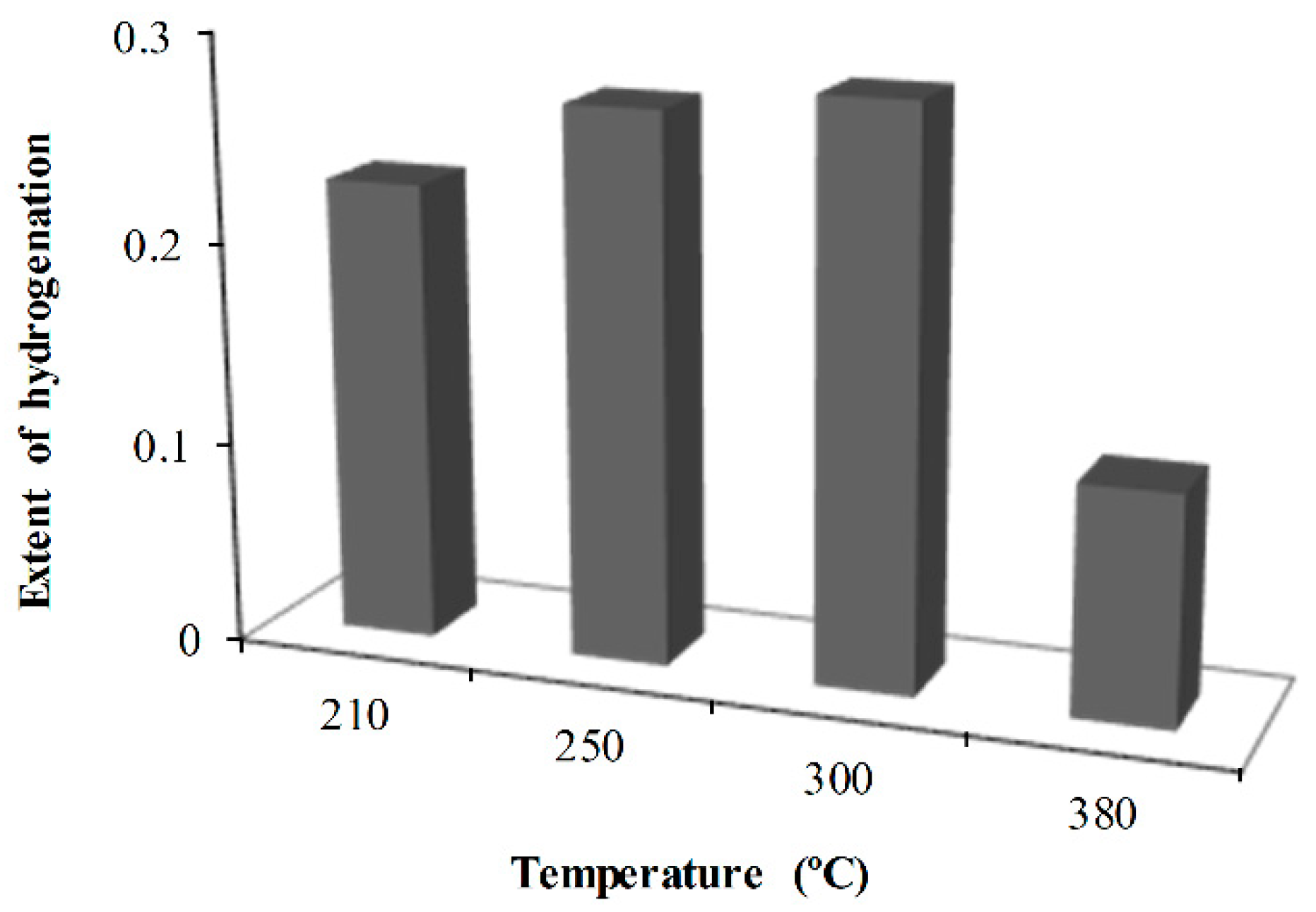
2.3. Effect of Reaction Temperature

Naphthalene hydrogenation was carried out from 210 to 380 °C at LHSV 0.75 h−1, pressure 18 bar, and catalyst/steel balls 70% (v/v) using NiMo. The mean extent of hydrogenation is shown in Figure 3. As the reaction temperature increases from 210 to 300 °C, the extent of hydrogenation of naphthalene increases from 0.23 to about 0.3, while further temperature increases to 380 °C resulted in a decrease to 0.11. Therefore, the catalyst had a higher hydrogenation activity at a temperature of 300 °C, which is consistent with that reported in the literature [23,24].
The observed drop in the extent of hydrogenation at 380 °C occurs because thermodynamically, the hydrogenation of aromatic compounds is unfavorable at higher reaction temperatures, which is due to their exothermic nature [23,25]. The evaluation of experimental data from a fixed-bed catalytic reactor is commonly established on the assumption of plug flow [26]. A first-order rate equation was used to express the kinetic data obtained from the hydrogenation of naphthalene at steady-state reaction conditions in the fixed-bed reactor [27]. Equation (3) was developed from a plug flow model and first-order rate law and was used to fit the experimental data from which rate constants and the apparent activation energy were determined. Figure 4 shows the plot of ln (1/(1 − X)) against W/F and the Arrhenius plot. The first-order reaction rate depicts the experimental data for both naphthalene and tetralin hydrogenation with an R2 value of 0.99. The rate of naphthalene hydrogenation is faster than that of tetralin with the rate constant in the ratio of 1:2.5 (tetralin/naphthalene) at 300 °C. This means it is easier to hydrogenate a double ring aromatic compound than a single ring aromatic counterpart.
Ln (1/(1 − X)) = k (W/F)
where X is conversion, k is the apparent rate constant, W is the catalyst weight, and F is the molar flow.
As expected, with an increase in reaction temperature from 210 to 300 °C, the rate constant increased, which is consistent with the effect of reaction temperature on the extent of hydrogenation of naphthalene. The apparent activation energy obtained was 16.3 kJ/mol. It is believed that a catalyst with higher activity shows lower activation energy, and it appears the NiMo/Al2O3 catalyst is internal mass transfer limited. In addition, external mass transfer effect existed within the catalyst since the flowrate was very low and the diameter of the reactor tube (20 mm) is far larger than the catalyst particle size [22]. The catalyst particle size diameters (1.4 mm × 1.21 mm) and length (5 ± 2.1 mm) also contributed to the experienced diffusion effect. The result for tetralin dehydrogenation has been reported elsewhere [28].

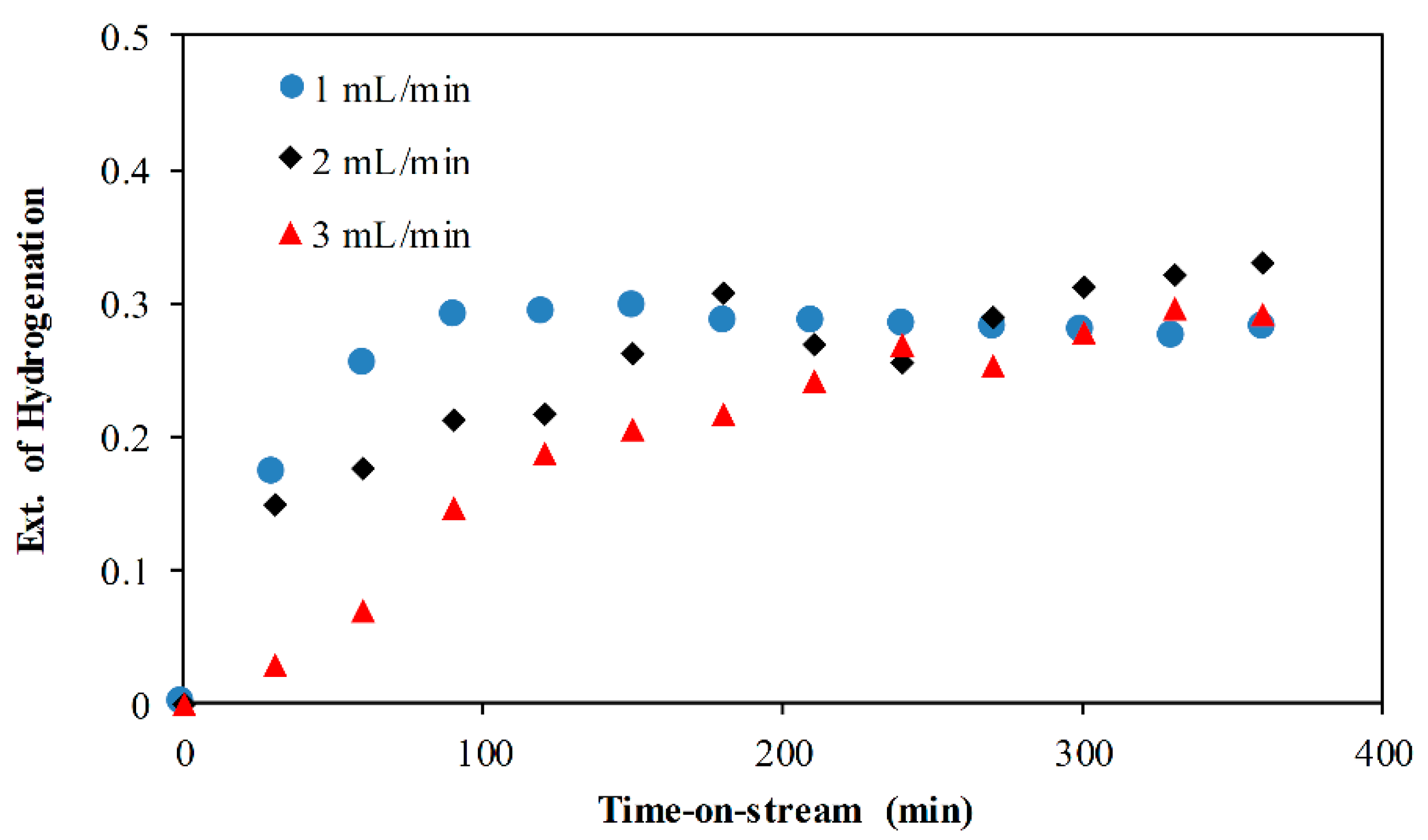
2.4. Effect of Flowrate

It is well known that a lower flowrate increases the residence time of the reactants and also improves the contact time between the reactants and the catalyst. The effect of feed rate on the extent of naphthalene hydrogenation is shown in Figure 5. Before 200 min, the extent of naphthalene hydrogenation increases as the flowrate decreases. This can be attributed to the catalyst start-up effect, which includes time needed to achieve steady state due to catalyst wetting and the diffusion of reactants into and products out of the pores of the catalyst [23,28]. Additionally, a lower flowrate increases the residence time of the naphthalene as well as the contact time between the reactants and the catalyst, thereby increasing the extent of hydrogenation. The contact time of the reactants with the catalyst is quite low at 3 mL/min coupled with a noticeable effect of mass transfer; hence, a lowered extent of hydrogenation is obtained. However, beyond 200 min, the extent of naphthalene hydrogenation is almost constant. On average, the extent of naphthalene hydrogenation is 0.273 (1 mL/min), 0.258 (2 mL/min), and 0.207 (3 mL/min). However, the slight difference indicates the variation in hydrogenation due to external mass transfer limitation from the surrounding fluid to the catalyst outer surface.

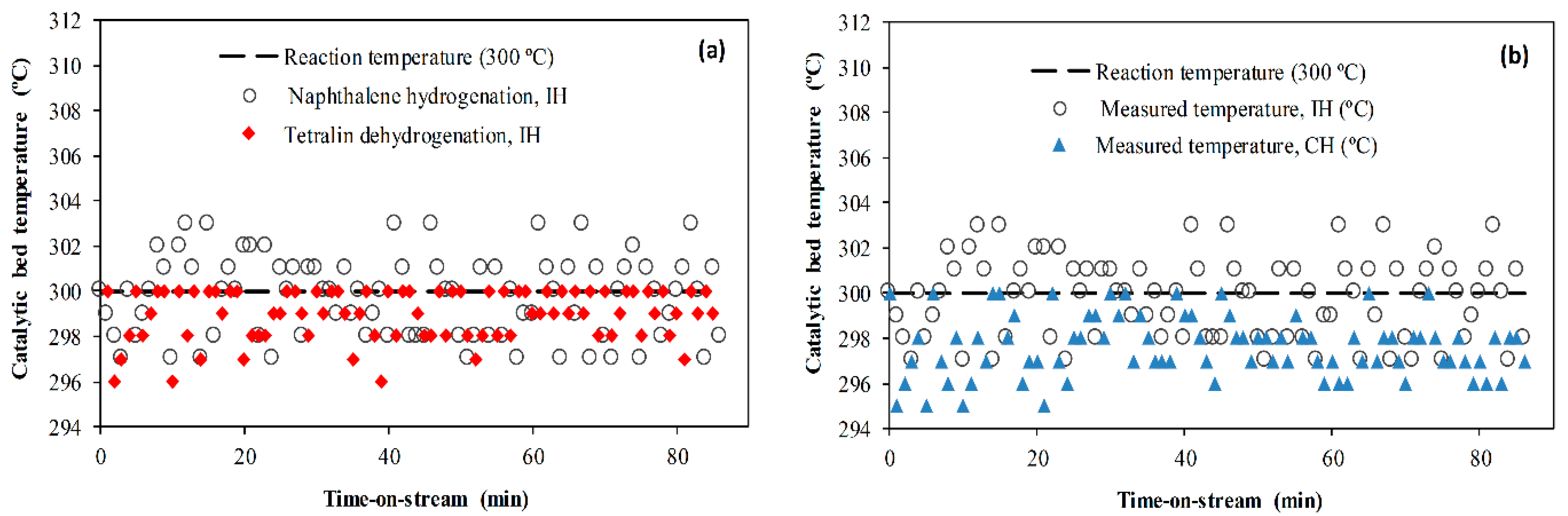
2.5. Effect of Heating Method

Inductive heating (IH) offers thermal advantage over conventional heating (CH), for 70% v/v (catalyst/steel balls), the steel balls rapidly heat the bed of the catalyst to 300 °C within 15 min, while conventional heating with a furnace took about 72 min to achieve the same temperature. This is because of the larger surface area, minimal heat losses, and lower thermal resistance offered by the steel balls’ inductively heated bed of the catalyst. The measured temperatures of the catalytic bed during naphthalene hydrogenation and tetralin dehydrogenation under IH and CH are shown in Figure 6. While naphthalene hydrogenation is exothermic, the reverse tetralin dehydrogenation is endothermic. Therefore, as the hydrogenation proceeds, heat is released and the catalytic bed temperature rises occasionally, which can be observed in Figure 6. The mean temperature of the catalytic bed during the reaction is 299.7 °C (naphthalene hydrogenation, IH), 297.6 °C (naphthalene hydrogenation, CH) and tetralin dehydrogenation 299.2 °C (IH) relative to the 300 °C reaction temperature. This suggests that the surface of the catalyst is hotter when heated inductively with steel balls than with furnace. Unlike the conventional system, the steel balls inductive heated-catalytic bed rapidly responded to changes in process conditions as shown in Figure 6. Therefore, the inductive heated-catalytic bed sustained the bed temperature approximately at the reaction temperature or slightly closer than the CH counterpart. Hence, the temperature gradient between the catalyst and surrounding fluid in the CH system is higher than the IH.
Figure 7 shows the naphthalene hydrogenation (exothermic) and tetralin dehydrogenation (endothermic) with IH and CH at temperature 300 °C, LHSV 0.75 h−1, pressure 18 bar, and catalyst/steel balls 70% (v/v) using NiMo catalyst. It can be observed that while CH favors naphthalene hydrogenation, IH was highly favorable to tetralin dehydrogenation. For the IH reactor, the steel balls enhanced the heat transfer between the fluid and the intimately contacted catalyst pellets compared with the CH method. The latter uses an external furnace to transfer heat through the reactor wall, and subsequently to the surrounding fluid and the catalyst, which is quite slow, as reflected in the catalyst bed temperature during reaction (Figure 6b). Therefore, since under IH, the catalyst surface is hotter, it promoted the endothermic dehydrogenation reaction, while the large temperature gradient in the CH absorbed the heat of reaction from naphthalene hydrogenation, which shifted the equilibrium and improved the extent of hydrogenation (Figure 6). Hence, at the reaction zone, the heat transfer rate and temperature gradients are different, influencing the extent of conversion. Moreover, the IH reactor could rapidly respond to changes in condition as shown in the superfluous periodic temperature rise in the catalytic bed (Figure 6), due to the heat of reaction released as the hydrogenation of naphthalene proceeds, forcing the conversion of naphthalene to approach equilibrium faster than with CH. Hence, naphthalene hydrogenation and tetralin dehydrogenation are influenced by the way in which heat is supplied to the catalytic bed.

2.6. Gaseous Products
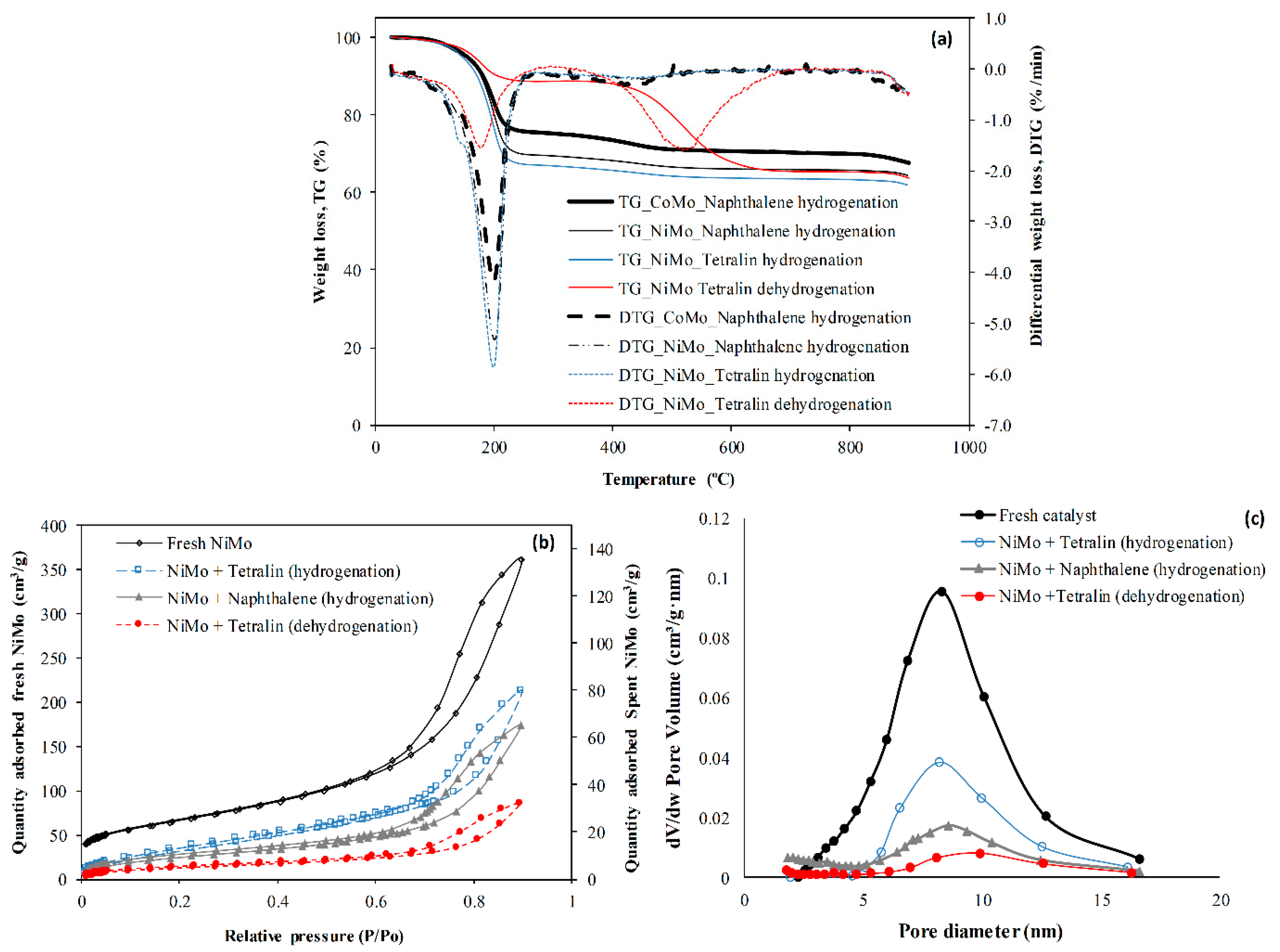
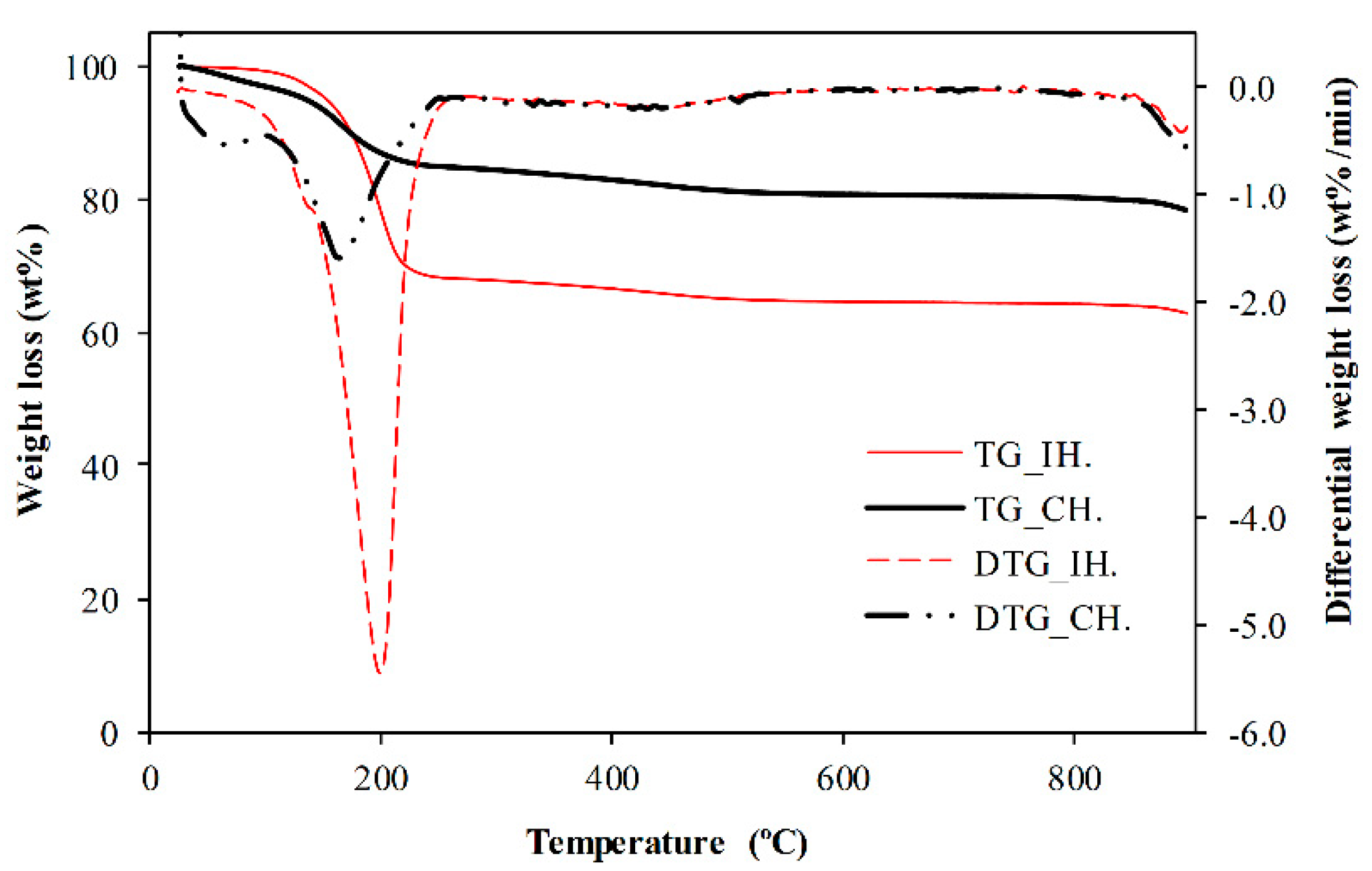
The saturation of the aromatic rings enhances ring opening and hydrocracking in which the C–C bond cleavage is promoted by the catalyst support [25,29]. Table 2 shows the composition of the gas stream for the hydrogenation of naphthalene and the dehydrogenation of tetralin at 300 °C using the NiMo/Al2O3 catalyst. The gaseous product from hydrogenation has no olefinic gases, which signify the dominance of hydrogenation and hydrocracking reactions. However, without hydrogen, aliphatic and naphthenic hydrocarbons experience dehydrogenation to olefins and aromatic compounds. In the upgrading of heavy oil, these reactions convert saturated compounds to unsaturated, and the cleavage of the C–H bond yields hydrogen and hydrocarbon radicals that could be detrimental to catalyst performance when the hydrocarbon radicals undergo addition reactions into bigger molecular weight hydrocarbons.
The olefins are very reactive and easily polymerize and condense into larger molecular weight hydrocarbons, and as a consequence of hydrogen abstraction, result in coke formation. It is important to note that about 20% hydrogen gas was liberated from tetralin due to dehydrogenation. This affirms the use of tetralin as a hydrogen-donor solvent in the catalytic upgrading of heavy oil.

2.7. Coke Formation

Figure 8 shows the spent catalyst weight loss and its differentials for NiMo and CoMo, the nitrogen sorption characteristics and pore distribution of NiMo after reactions at a temperature of 300 °C under an inductive heated catalytic bed. Table 3 displays the summary of the NiMo catalyst surface area and pore volume before and after 6 h reactions. The weight loss from 25 to 260 °C can be attributed to the removal of residual naphthalene/tetralin and n-hexadecane solvent on the spent catalyst, and beyond that, the weight loss can be regarded as the deposited coke burn-off in Figure 8a [23]. It can be seen that the extent of catalyst pore plugging was highest with tetralin dehydrogenation, followed by naphthalene hydrogenation, and the least is tetralin hydrogenation (Figure 8b,c). The narrower pores experienced severe pore plugging to a greater extent than the pores with sizes greater than 5 nm (Figure 8c). Since the shape of the hysteresis loops is unchanged (Figure 8b), it suggests that the pores become progressively narrower during the reaction as coke formation increases.
It can be observed in Figure 8c and Table 3 that a significant loss of surface area and pore volume occur in the spent catalysts with tetralin dehydrogenation showing the highest loss relative to the fresh NiMo/Al2O3 catalyst. The coke produced in naphthalene hydrogenation was 3.3% (NiMo) against 3.9% (CoMo). The slightly lower coke formation observed with NiMo catalyst over CoMo is due to the superior hydrogenation activity exhibited by the Ni promoter over the Co counterpart (Figure 2a). Consequently, the hydrogenation of naphthalene with NiMo catalyst produced more coke than tetralin hydrogenation (2.8%). This can be attributed to the double ring over single ring in addition to naphthalene being more strongly absorbed than tetralin onto the catalyst surface during hydrogenation [25]. On the other hand, the dehydrogenation of tetralin produced about 19.4% coke, which is far higher than tetralin and naphthalene hydrogenation. In other words, dehydrogenation results in more coke formation compared to hydrogenation. Hence, hydrogen plays the role of saturating olefins and aromatics, which readily polymerizes and condenses into coke through hydrogen abstraction.
The coke formation for the hydrogenation of naphthalene under IH and CH at 300 °C is shown in Figure 9. The recovered catalyst coke content after 6 h time-on-stream experiments is 4.02% (CH) and 3.36% (IH). The coke formed when the reaction was carried out with an inductive heated (IH) catalytic bed is slightly lower than with CH in spite the hydrogenation of naphthalene being slightly improved with CH compared with IH (Figure 7a).
This is because the intimate contact between the steel balls and catalyst induces rapid heat transfer in the IH reactor, which enhances the desorption of strongly absorbed residual naphthalene and its products tetralin and decalins from the surface of the catalyst, unlike the slow heat transfer experienced with the CH system. The magnetic field creates non-thermal effects such as the polarization of the reactant molecules and enhanced transport of species in the reaction medium. It has been reported that this non-thermal effect increases the reaction rate, due to the decrease in reaction time [30]. This is because the interaction of the magnetic field with the catalyst surface can modify its properties, thereby influencing the adsorption and desorption energy of the molecules onto the catalyst surface [30,31]. This non-thermal effect of the IH catalytic bed could have contributed to decreasing the coke formation.

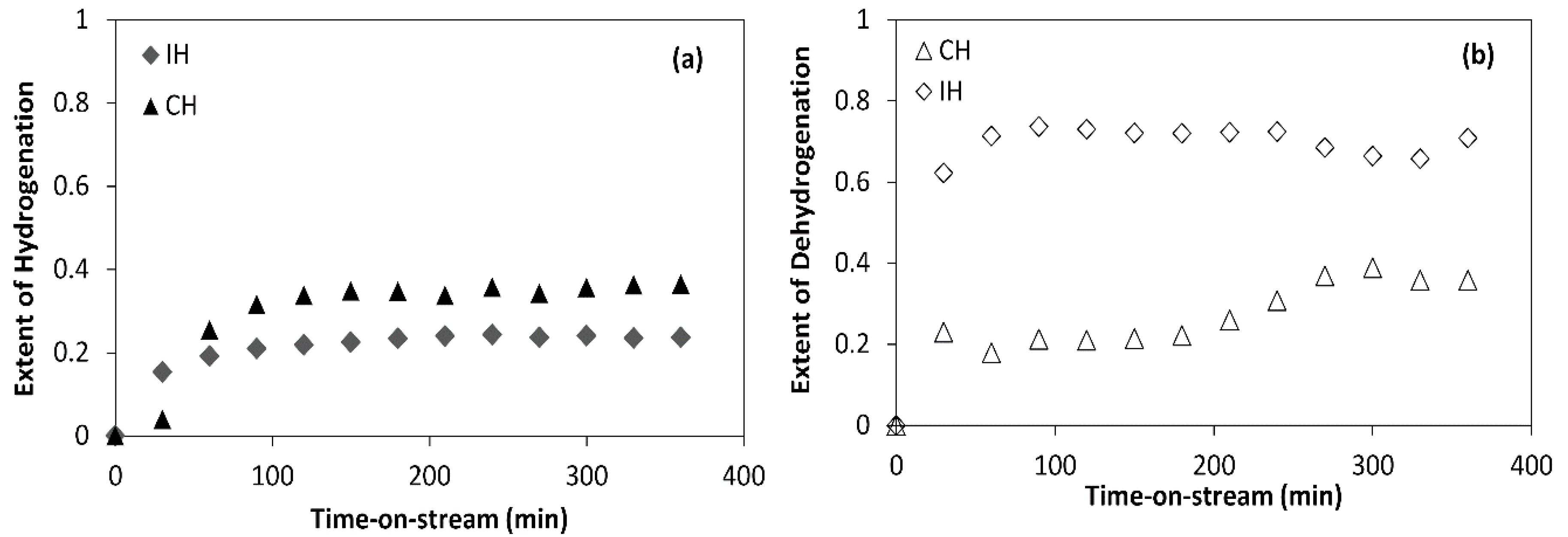
2.8. The Roles of Hydrogen in Catalytic Upgrading of Heavy Oil

The roles of catalyst and hydrogen in the direct catalytic upgrading of heavy oils involves complex reactions such as the thermal cracking of C–C, C–H, and C-heteroatom bonds, hydrocracking, and the hydrogenation of poly-aromatic components. Hence, it is essential to evaluate qualitatively and quantitatively the roles of hydrogen using model compounds that mimic the polycyclic aromatic compounds found in heavy oil.
In Table 2, under nitrogen environment, olefins were observed in the gaseous product of tetralin dehydrogenation. Although tetralin is used as hydrogen-donor solvent in heavy oil upgrading, without hydrogen gas, the naphthenic and aliphatic components of heavy oil readily experience hydrogen abstraction to produce olefins and condensed aromatic species. Whilst the olefins are very reactive and easily polymerize into larger molecular weight hydrocarbons, the aromatic species strongly absorbed on the catalyst surface, resulting in higher coke formation. The formation of a higher percentage of coke in tetralin dehydrogenation can be attributed to the formation of strongly absorbed naphthalene. Aromatics adsorb on the catalyst active sites and react with hydrogen. Kirumakki et al. [25] found that naphthalene adsorbed more than twice as strongly as tetralin on the surface of NiO/SiO2–Al2O3 catalyst with the ratio of the adsorptive constants naphthalene-to-tetralin 2.18 at 200 °C. Hence, one of the roles of hydrogen in the catalytic upgrading of heavy oil is to saturate reactive olefins and hydrogenate aromatic species. This can be seen in the aliphatic gases produced from naphthalene hydrogenation while yielding partially hydrogenated compound tetralin and subsequently fully hydrogenated compound decalin. Second, hydrogen enhances the desorption of cracked and hydrogenated products from the surface of the catalyst, which can be observed from naphthalene and tetralin hydrogenations to tetralin and decalin. The hydrogenation of tetralin yields lower coke than naphthalene hydrogenation, while the dehydrogenation of tetralin to naphthalene produced the highest coke. Therefore, the formation of aliphatic and naphthenic hydrocarbons in the presence of hydrogen gas could improve the fuel distillate fractions such as naphtha and diesel in the upgraded oil (Table 2 and Figure 2). The gases observed in Table 2 are reflections of the reactions in the liquid phase and are products of naphthalene rings saturation, ring opening, and hydrocracking promoted by the catalyst in the pressure of hydrogen gas. This suggests that the addition of hydrogen will promote the removal of associated heteroatoms such as sulfur and nitrogen within the polyaromatic structures.
Heavy oil is known to be deficient in hydrogen. Therefore, the liberation of hydrogen gas and hydrogen-rich gases (i.e., methane and ethane) during the upgrading is detrimental to the quality of the upgraded oil as well as the catalyst due to coking [13,32]. This can be confirmed also from tetralin reaction under nitrogen atmosphere, in which it can be observed that a substantial amount of hydrogen gas is produced while more condensed arenes (i.e., naphthalene) which adhered strongly to the catalyst surface formed, resulting in high coke formation and high catalyst pore plugging (Figure 8). The catalytic upgrading of heavy oils is commonly performed at high temperatures 350–425 °C. At these temperatures, thermal decomposition produces free radicals from the cleavage of C–H, C–C, and C–heteroatom bonds. Without hydrogen gas, these free radicals polymerize and condense into bigger molecules, which adsorb strongly on the surface of the catalyst, and with subsequent addition reactions, they plug the catalyst pores and channels, resulting in high coke formation (see Figure 8 and Table 3). It is clear that the hydrogenation of naphthalene causes the NiMo/Al2O3 catalyst to lose more surface area and pore volume compared to tetralin hydrogenation. On the other hand, tetralin dehydrogenation causes more catalyst pore plugging than the hydrogenation of tetralin and naphthalene. Therefore, hydrogen gas addition will promote the desorption of hydrogenated radicals from the catalyst surface while halting free radical’s addition reactions to improve fuel distillate fractions, hence reducing pore plugging and suppressing coke formation [10]. Since the catalyst surface is hotter with steel balls inductive heated catalyst bed than conventional heated via furnace (Figure 6), it suggests that under hydrogen-rich environment, the desorption of hydrogenated molecule would be enhanced as well [20].

3. Materials and Methods

3.1. Materials

Quadra-lobe shaped extrudates NiMo/Al2O3 and CoMo/Al2O3 catalysts (AkzoNobel, Amsterdam, Netherlands) with diameters of 1.4 mm × 1.21 mm and lengths of 5 ± 2.1 mm were used. Steel balls of 3 mm diameter were used as susceptors to volumetrically heat the mixed catalyst bed via induction. The feedstock was naphthalene (99+%, Alfa Aesar, Heysham, UK) and tetralin (99%, Sigma-Aldrich, Gillingham, UK) dissolved in n-hexadecane (99%, Alfa Aesar, Heysham, UK) solvent and gas (nitrogen, N2 and hydrogen, H2); cylinder gases were supplied by the British Oxygen Company (BOC) group, Birmingham, UK.

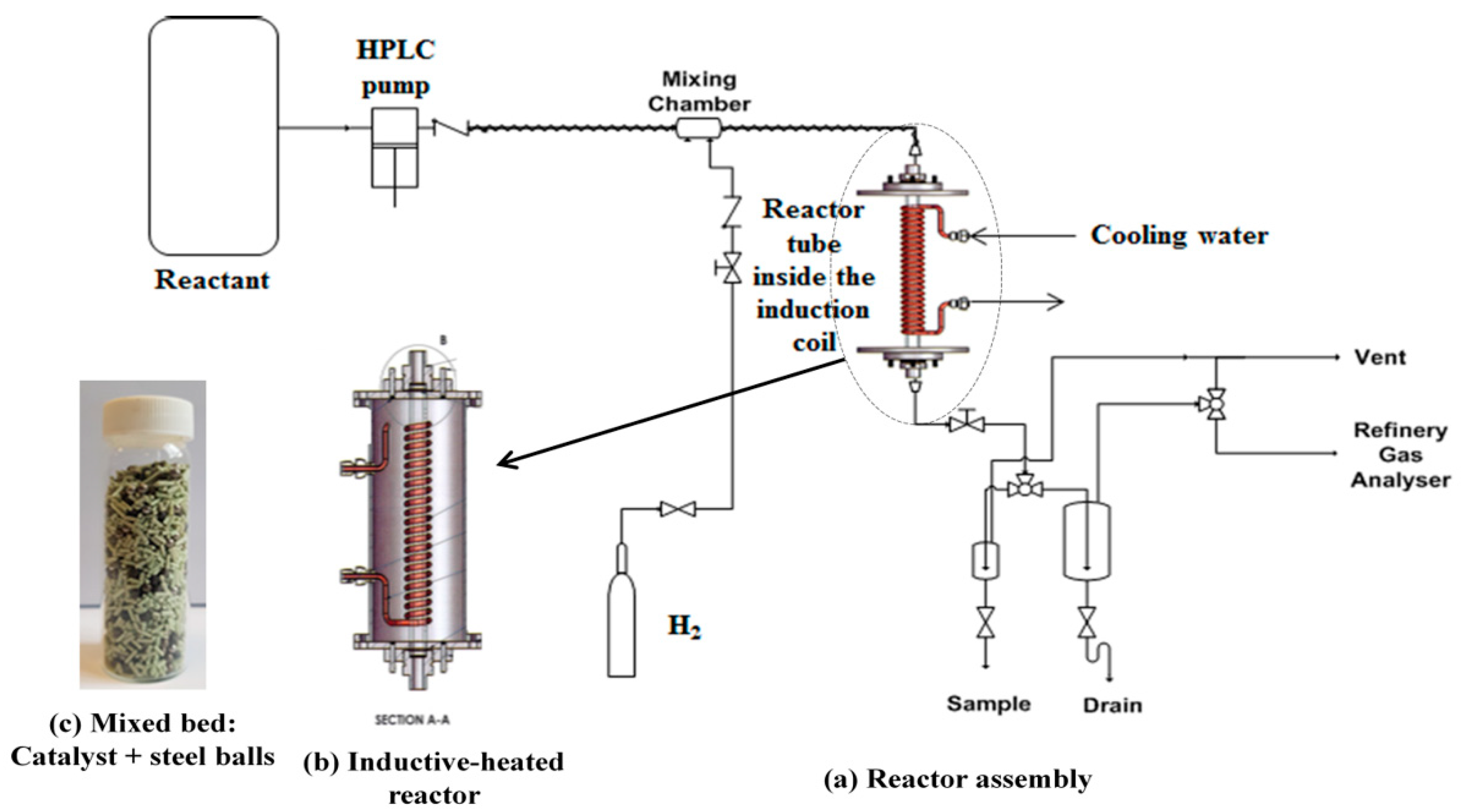
3.2. Lab-Scale Inductive Heated Catalytic Reactor

The schematic diagram of the lab-scale inductive heated catalytic reactor is shown in Figure 10. The reactor design consists of an induction coil wrapped around a quartz glass tube [440 mm × 20 mm (inner diameter, i.d) × 40 mm (outer diameter, o.d), and rated 20 bar] as shown in Figure 10b. Before the use of inductive heating, an ohmic system was applied; instead of heating, electrical arcing was observed. Therefore, it was discontinued. The apparatus was commissioned at the School of Chemical Engineering, University of Birmingham, UK. The inductive unit was built by Inductelec Ltd., Chesterfield UK, and the reactor unit was built by C-Tech Innovation, Chester UK. Since the glass is non-conductive, the heat generated inside the mixed catalytic bed (Figure 10c) is due to the conducting steel balls (3 mm). The height of catalytic bed is the same as the length of the induction coil wrapped around the quartz tube (Figure 10b), which is 230 mm. The susceptor steel balls converted the electromagnetic energy (i.e., eddy current and magnetic field) into heat and volumetrically heat the catalytic bed. To avoid over heating during the reaction, cooling water is continually passed through the induction coil, while the reactor housing is saturated with the passage of nitrogen gas. The top and bottom of the catalytic bed were packed with 5 mm glass beads to enhance fluid distribution and improve wetting and radial contact. The catalytic bed voidage is 0.38, the volumetric flux of the hydrogen/nitrogen gas (10.53 cm/s) and that of the liquid (0.053–0.16 cm/s) depending on the feed rate from 1 to 3 mL/min. Since the gas flux is much higher than that of the liquid, a spray flow is experienced based on a Baker flow regimes diagram [33]. The inductive heater was operated at a frequency of 41 kHz, the magnetic field and the eddy current generate heat within the catalytic bed from I2R losses through the resistivity of the steel balls. The steel balls are rapidly heated, and the generated heat is transferred to the intimately contacted catalyst pellets. The catalyst bed height is the same as the induction coil loop length, which is 230 mm. The temperature of the catalyst bed was monitored with a thermocouple (type K) installed from the reactor bottom to the center of the bed. The reactor is operated in a downward flow mode to simulate the gravity drainage of the mobile oil zone of the THAI process. The feeds were preheated to 190 °C with the aid of the trace heater cable wrapped around the delivery line.
A hydrogen flow of 200 mL/min was used, and the catalyst was reduced under hydrogen atmosphere for 30 min at 250 °C at 5 bar, which converts the respective metal oxides of Mo, Ni, and Co into their active metal phase. The experiment was initiated by starting the HPLC (high-performance liquid chromatography) pump once the desired reaction temperatures and hydrogen pressure had been achieved. The pressure inside the reactor tube was regulated by a back-pressure regulator, while cooling water is continually passed through the induction coil to prevent overheating. A control experiment was carried out for conventional heating (i.e., heat supplied externally using furnace) with the same experimental setup, which has been reported in the literature [6]. After the hydrogenation/dehydrogenation reactions, the product stream passes through the back-pressure regulator into the gas–liquid separator, where the gas flashed off from the liquid product. The liquid products are collected every 30 min, and the gas was vented or sent to the Refinery Gas Analyzer (RGA) for compositional determination by gas chromatography. The experimental conditions are temperatures 210–380 °C, flowrate 1–3 mL/min (LHSV 0.75–2.25 h−1), catalyst/steel balls ratio 70% (v/v), gas pressure 18 bar, and gas (H2 or N2) flowrate 200 mL/min. It is important to note that at a catalyst/steel ball ratio of 70% (v/v), it was found that the effect of the electromagnetic field upon the measured temperature by the thermocouple (1 mm) is significantly diminished due to shielding by the non-conducting catalyst surrounding it as well as the thickness of the quartz glass tube (20 mm i.d, 40 mm o.d). This optimization of CTSBR was carried out to minimize the effect of the magnetic field on the thermocouple, because it is technically challenging to incorporate an infrared radiation thermometer to measure the temperature of the catalytic bed in the inductive heated reactor. Hence, the temperature measured by the installed thermocouple is also validated with another thermocouple inserted into the catalytic bed once the induction heating achieves the desired temperature and is turned off, removing the interfering influence of the magnetic field. It was discovered that the two measurements by the installed and inserted thermocouples once the induction was turned off is approximately the same; the procedure details have been reported elsewhere [28]. The temperature difference observed between the thermocouple inserted from the top of the bed and that measured by the installed thermocouple from the bottom to the center of the bed is approximately 1 °C. This suggests that a uniform temperature is established inside the catalyst bed heated with steel balls via induction. On the other hand, the conventional heating experiment via an electrical furnace was carried with an identical set-up, except the reactor tube is stainless steel with 20 mm inner diameter (i.d).

3.3. Analytical Methods

The catalyst surface area was determined by the nitrogen adsorption technique using a Micrometritics Analytical Instrument ASAP® 2010 (Micromeritics Instrument Corporation, Norcross, GA, USA), with analysis via the Brunauer–Emmett–Teller (BET) model according to ASTM C1274, and the pore size and volume were determined by Barrett–Joyner–Halenda (BJH) model. The X-ray diffraction (XRD) data of the catalyst were collected with Cu Kα radiation from 10 to 80° 2θ and a step width size of 0.025° using a Bruker AXS GmbH (D8 Advanced XRD, Karlsruhe, Germany).
The liquid product from the reactions was analyzed using a gas chromatograph (GC) Agilent Technologies 6890N Network GC System (Agilent Technologies, Santa Clara, CA, USA) integrated with a HP-5 (30 m × 0.320 mm × 0.25 μm) capillary column. The GC oven temperature was set at 120 °C for 3 min and then ramped to 200 °C at 10 °C/min and held at 200 °C for 4 min. Gas flows: hydrogen (40 mL/min), air (450 mL/min), and helium (38 mL/min). The used catalyst after the hydrogenation reaction was subjected to thermogravimetric analysis (TGA) (TG 209 F1 Iris® instrument, NETZSCH-Geratebau GmbH, Selb, Germany) to estimate deposited coke. The produced gas from the reactions was analyzed using Agilent 7890A RGA, with details reported in Hart et al. [6].

4. Conclusions

Condensed arenes extensively exist in heavy oil and are a complex class of hydrocarbons with many fused benzene rings. They confer poor quality on the oil such as low API gravity and high viscosity, and their environmental impact is reflected in downstream products such as diesel fuel. In this study, naphthalene and tetralin hydrogenation and dehydrogenation as model compounds that mimic polycyclic aromatic compounds found in heavy oil were studied using NiMo/Al2O3 and CoMo/Al2O3 catalysts heated with steel balls inductively. The effect of temperature and flowrate were studied the range of 210–380 °C and 1–3 mL/min at pressure 18 bar, catalyst/steel balls 70 (v/v), and gas (H2 or N2) 200 mL/min.
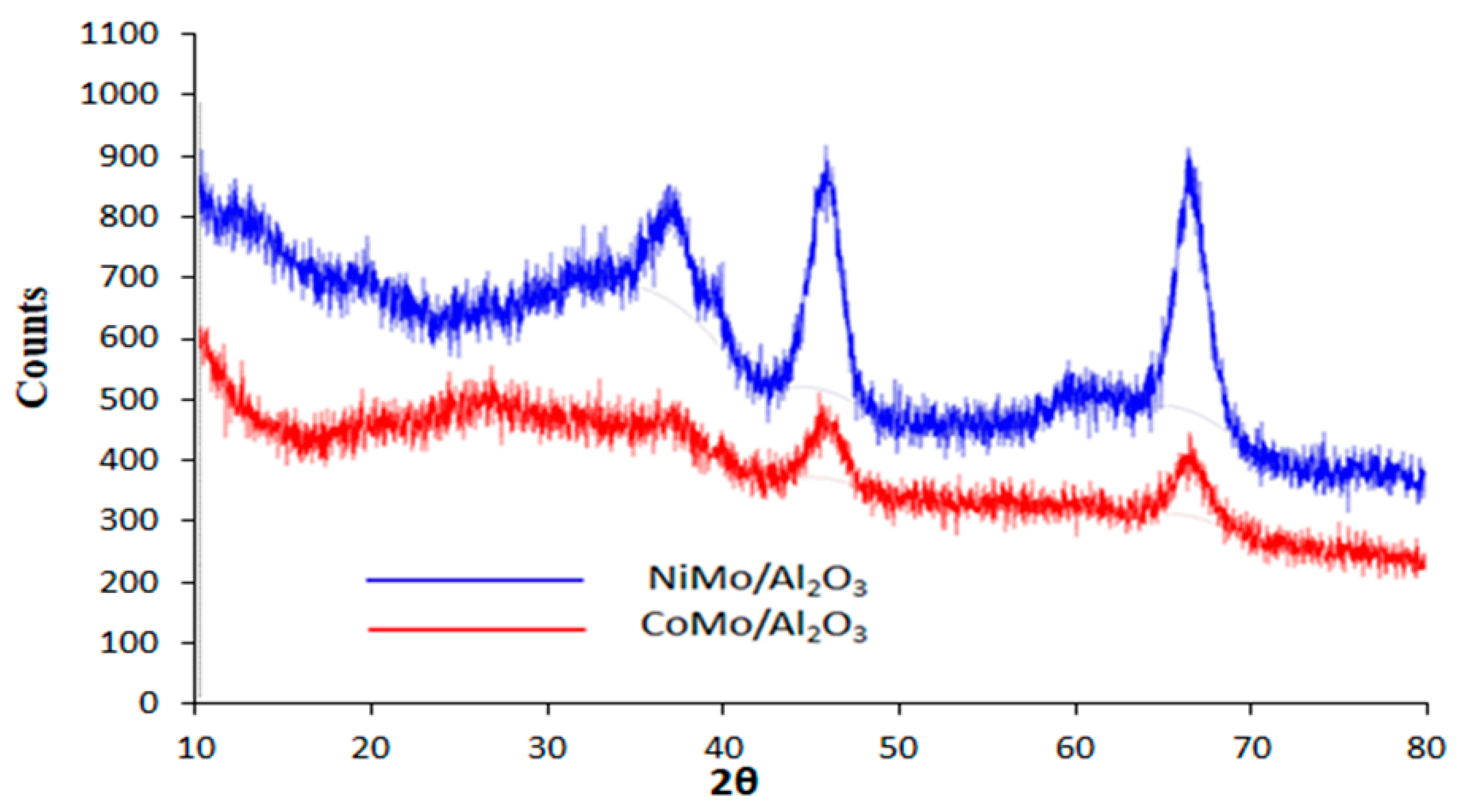
  • It was found that the Ni metal promoter enhanced the hydrogenating activity of Mo supported on an alumina catalyst more than Co. Hence, a lower coke deposit was observed with the NiMo/Al2O3 catalyst than with the CoMo/Al2O3 counterpart.
  • The effect of reaction temperature showed that naphthalene hydrogenation increased as the temperature increased from 210 to 300 °C and decreased when the temperature was further increased to 380 °C. On the other hand, as the flowrate increased from 1 to 3 mL/min, naphthalene hydrogenation decreased with 1 and 2 mL/min, giving approximately the same extent of hydrogenation.
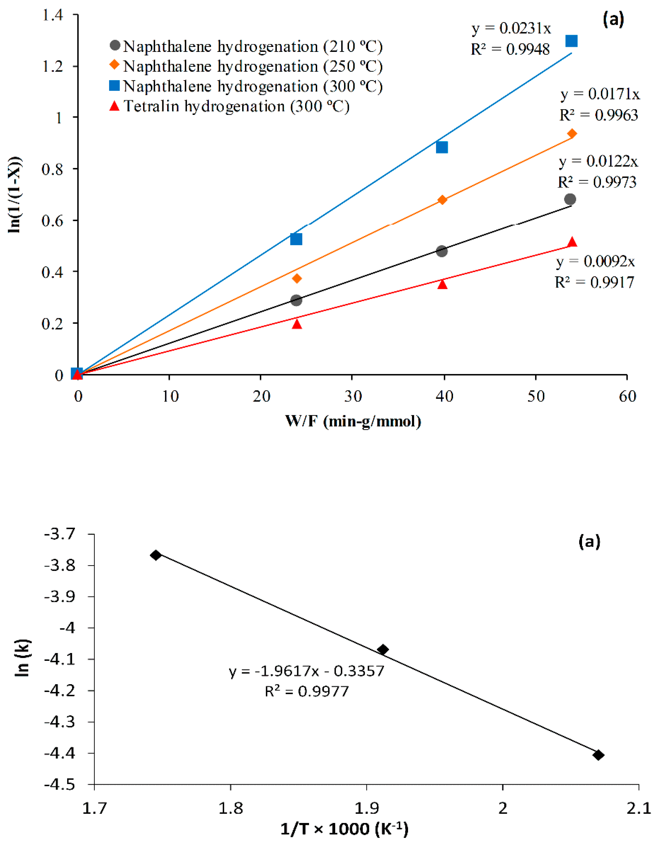
  • The kinetic data from the fixed-bed inductive heated catalytic with steel balls were evaluated with a first-order reaction rate on the assumption of plug flow. The experimental data were fitted 99% by the first-order rate equation, and 16.3 kJ/mol apparent activation energy was obtained for naphthalene hydrogenation using NiMo/Al2O3, a temperature range of 210–300 °C, pressure 18 bar, flowrate 1 mL/min, and catalyst/steel balls 70% v/v.
  • With nitrogen gas environment, the naphthenic and aliphatic hydrocarbons lose hydrogen to form olefins and aromatic compounds. As a consequence, higher coking was observed in tetralin dehydrogenation under nitrogen atmosphere than tetralin and naphthalene hydrogenation using a NiMo/Al2O3 catalyst.
  • A smaller temperature gradient was found when the NiMo/Al2O3 catalyst was heated with steel balls (catalyst/steel balls, 70% v/v) through induction compared to conventional heating via a furnace. Hence, it was thermodynamically favorable to endothermic tetralin dehydrogenation than exothermic tetralin and naphthalene hydrogenation reaction.
  • Lower coke formation was observed in the NiMo/Al2O3 catalyst heated inductively with steel balls than conventional heating for naphthalene hydrogenation. This is because the smaller temperature gradient between the catalyst and surrounding fluid, as well as the non-thermal effect of magnetic field, enhanced the desorption and transport properties of the naphthalene and its hydrogenated products (i.e., tetralin and decalins) when heated inductively.
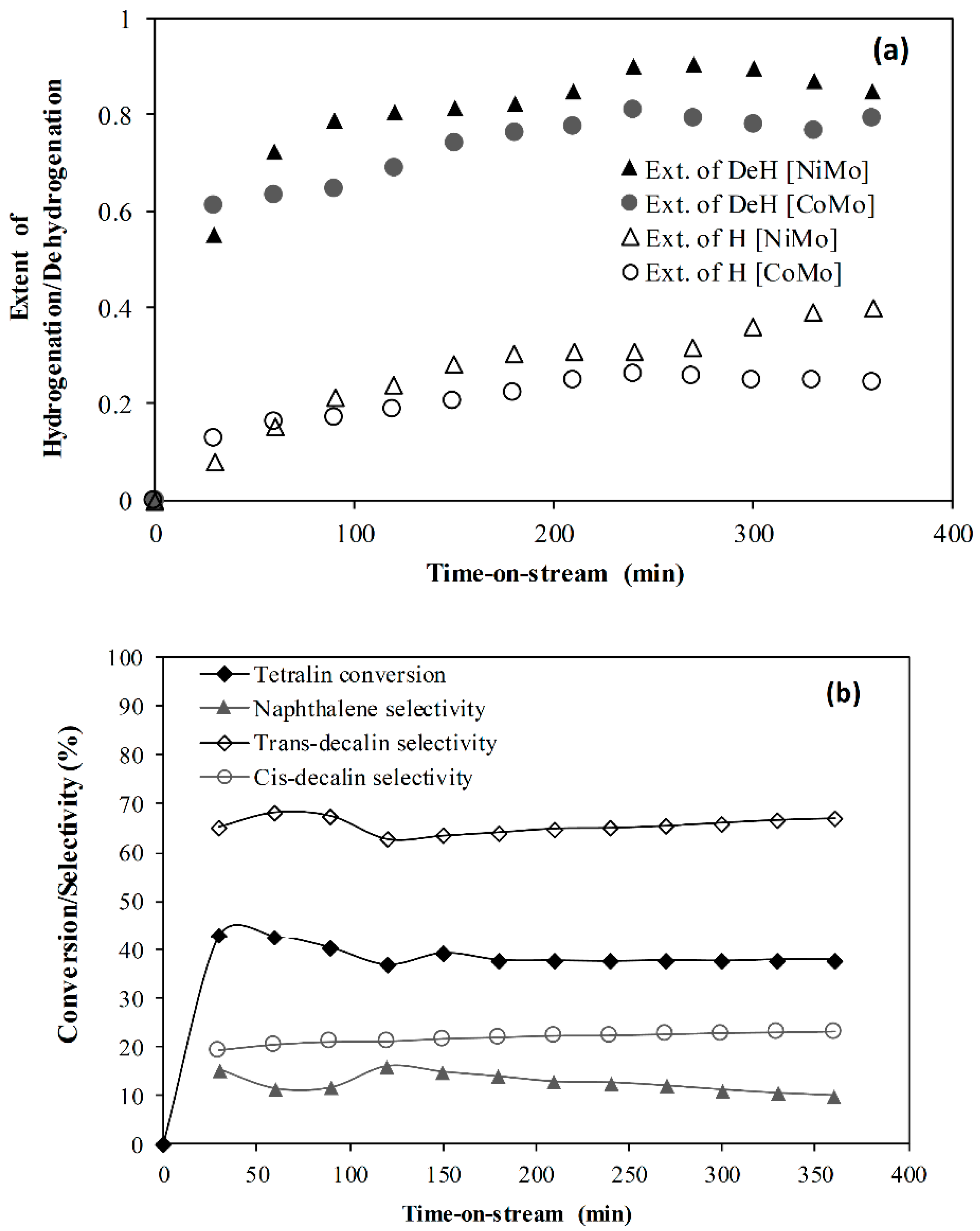
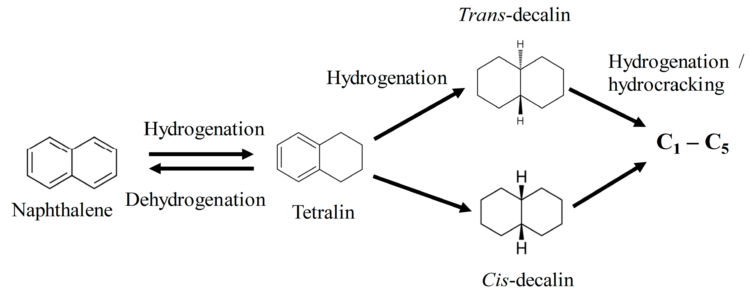
  • The rate of naphthalene hydrogenation is higher than that of tetralin. However, the dehydrogenation of tetralin caused more coking and catalyst pore plugging than the hydrogenation of tetralin and naphthalene. This is because of the deposition of strongly adsorbed condense arenes naphthalene and other polymerization reactions due to the presence of olefins and aromatic compounds.
Conclusively, the integration of induction heating to the CAPRI zone of the THAI process will be beneficial to heavy oil upgrading, since most of the cracking reactions are endothermic and would enhance hydrogen gas liberation to promote in situ hydroconversion when combined with a hydrogen-donor solvent such as tetralin or decalin.

Author Contributions

Conceptualization, J.W. and A.H.; methodology, J.W., M.A. and A.H.; investigation, A.H.; resources, J.W.; writing—original draft preparation, A.H.; writing—review and editing, J.W., M.A., J.P.R. and S.P.R.; supervision, J.W. and S.P.R.; project administration, S.P.R., J.W. and J.P.R.; funding acquisition, S.P.R., J.W. and J.P.R. All authors have read and agreed to the published version of the manuscript.

Funding

This research work was funded by the Engineering and Physical Science Research Council (EPSRC), UK, grant number EP/N032985/1.

Acknowledgments

The authors acknowledge with thanks the technical support of John Wedderburn, School of Metallurgy and Materials, University of Birmingham, UK, on the nitrogen adsorption–desorption isotherm of the catalyst used in this work. We are grateful to David Boylin and Andrew Tanner for their technical assistance with the experimental rig maintenance.

Conflicts of Interest

The authors declare no conflict of interest.

References

  1. Zadražil, A.; Štěpánek, F. Remote control of reaction rate by radiofrequency heating of composite catalyst pellets. Chem. Eng. Sci. 2015, 134, 721–726. [Google Scholar] [CrossRef]
  2. Varsano, F.; Bellusci, M.; Provini, A.; Petrecca, M. NiCo as catalyst for magnetically induced dry reforming of methane. IOP Conf. Ser. Mater. Sci. Eng. 2018, 323, 012005. [Google Scholar] [CrossRef]
  3. Idakiev, V.V.; Marx, S.; Roßau, A.; Bück, A.; Tsotsas, E.; Mörl, L. Inductive heating of fluidized beds: Influence on fluidization behavior. Powder Technol. 2015, 286, 90–97. [Google Scholar] [CrossRef]
  4. Vinum, M.G.; Almind, M.R.; Engbaek, J.S.; Vendelbo, S.B.; Hansen, M.F.; Frandsen, C.; Bendix, J.; Mortensen, P.M. Dual-Function Cobalt–Nickel Nanoparticles Tailored for High-Temperature Induction-Heated Steam Methane Reforming. Angew. Chem. Int. Ed. 2018, 57, 10569–10573. [Google Scholar] [CrossRef] [Green Version]
  5. How Much Crude Oil Has the World Really Consumed? Available online: https://oilprice.com/Energy/Crude-Oil/How-Much-Crude-Oil-Has-The-World-Really-Consumed.html, (accessed on 25 August 2019).
  6. Hart, A.; Shah, A.; Leeke, G.; Greaves, M.; Wood, J. Optimization of the CAPRI Process for Heavy Oil Upgrading: Effect of Hydrogen and Guard Bed. Ind. Eng. Chem. Res. 2013, 52, 15394–15406. [Google Scholar] [CrossRef]
  7. Upreti, S.R.; Lohi, A.; Kapadia, R.A.; El-Haj, R. Vapor Extraction of Heavy Oil and Bitumen: A Review. Energy Fuels 2007, 21, 1562–1574. [Google Scholar] [CrossRef]
  8. Shah, A.; Fishwick, R.P.; Leeke, G.A.; Wood, J.; Rigby, S.P.; Greaves, M. Experimental optimisation of catalytic process in situ for heavy-oil and bitumen upgrading. J. Can. Petrol. Technol. 2011, 50, 33–47. [Google Scholar] [CrossRef]
  9. Mazyar, O.A. In-situ hydrogenation of aromatic compounds for heavy oil upgrading. US Patent, No. 9,169,448 B2, 27 October 2015. [Google Scholar]
  10. Hart, A.; Wood, J. In Situ Catalytic Upgrading of Heavy Crude with CAPRI: Influence of Hydrogen on Catalyst Pore Plugging and Deactivation due to Coke. Energies 2018, 11, 636. [Google Scholar] [CrossRef] [Green Version]
  11. Galadima, A.; Muraza, O. Ring opening of hydrocarbons for diesel and aromatics production: Design of heterogeneous catalytic systems. Fuel 2016, 181, 618–629. [Google Scholar] [CrossRef]
  12. Monteiro-Gezork, A.C.A.; Natividad, R.; Winterbottom, J.M. Hydrogenation of naphthalene on NiMo- Ni- and Ru/Al2O3 catalysts: Langmuir–Hinshelwood kinetic modelling. Catal. Today 2008, 130, 471–485. [Google Scholar] [CrossRef]
  13. Hart, A.; Wood, J.; Greaves, M. In situ catalytic upgrading of heavy oil using a pelletized Ni-Mo/Al2O3 catalyst in the THAI process. J. Pet. Sci. Eng. 2017, 156, 958–965. [Google Scholar] [CrossRef]
  14. Petrobank Energy and Resources Ltd. Strength in Heavy Oil: Growing THAITM Globally. 2018. Available online: https://www.knotia.ca/kstore/productinfo/fric08/PDFs/Petrobank%20Energy%20and%20Resources%20Ltd.%20AR_2007.pdf (accessed on 29 February 2018).
  15. Hu, L.; Li, H.; Babadagli, T.; Ahmadloo, M. Experimental investigation of combined electromagnetic heating and solvent-assisted gravity drainage for heavy oil recovery. J. Pet. Sci. Eng. 2017, 154, 589–601. [Google Scholar] [CrossRef]
  16. Sadeghi, A.; Hassanzadeh, H.; Harding, T.G. Modeling of desiccated zone development during electromagnetic heating of oil sands. J. Pet. Sci. Eng. 2017, 154, 163–171. [Google Scholar] [CrossRef]
  17. Jha, A.C.K.N. Heavy-Oil Recovery from Thin Pay Zones by Electromagnetic Heating. Energy Sources 1999, 21, 63–73. [Google Scholar] [CrossRef]
  18. Pizarro, J.; Trevisan, O. Electrical Heating of Oil Reservoirs: Numerical Simulation and Field Test Results. J. Pet. Technol. 1990, 42, 1320–1326. [Google Scholar] [CrossRef]
  19. Abu-Laban, M.; Muley, P.D.; Hayes, D.J.; Boldor, D. Ex-situ up-conversion of biomass pyrolysis bio-oil vapors using Pt/Al2O3 nanostructured catalyst synergistically heated with steel balls via induction. Catal. Today 2017, 291, 3–12. [Google Scholar] [CrossRef]
  20. Hart, A.; Adam, M.; Robinson, J.P.; Rigby, S.P.; Wood, J. Tetralin and Decalin H-Donor Effect on Catalytic Upgrading of Heavy Oil Inductively Heated with Steel Balls. Catalysts 2020, 10, 393. [Google Scholar] [CrossRef] [Green Version]
  21. Liu, F.; Xu, S.; Cao, L.; Chi, Y.; Zhang, T.; Xue, D. A Comparison of NiMo/Al2O3Catalysts Prepared by Impregnation and Coprecipitation Methods for Hydrodesulfurization of Dibenzothiophene. J. Phys. Chem. C 2007, 111, 7396–7402. [Google Scholar] [CrossRef]
  22. Zhan, X.; Guin, J.A. High-Pressure Hydrogenation of Naphthalene Using a Reduced Iron Catalyst. Energy Fuels 1994, 8, 1384–1393. [Google Scholar] [CrossRef]
  23. Hassan, F.; Al-Duri, B.; Wood, J. Effect of supercritical conditions upon catalyst deactivation in the hydrogenation of naphthalene. Chem. Eng. J. 2012, 207, 133–141. [Google Scholar] [CrossRef]
  24. Usman, M.; Li, D.; Razzaq, R.; Yaseen, M.; Li, C.; Zhang, S.-J. Novel MoP/HY catalyst for the selective conversion of naphthalene to tetralin. J. Ind. Eng. Chem. 2015, 23, 21–26. [Google Scholar] [CrossRef]
  25. Kirumakki, S.; Shpeizer, B.; Sagar, G.; Chary, K.; Clearfield, A. Hydrogenation of Naphthalene over NiO/SiO2–Al2O3 catalysts: Structure–activity correlation. J. Catal. 2006, 242, 319–331. [Google Scholar] [CrossRef]
  26. Huang, T.-C.; Kang, B.-C. Kinetic Study of Naphthalene Hydrogenation over Pt/Al2O3 Catalyst. Ind. Eng. Chem. Res. 1995, 34, 1140–1148. [Google Scholar] [CrossRef]
  27. Williams, M.F.; Fonfe, B.; Woltz, C.; Jentys, A.; Van Veen, J.A.R.; Lercher, J.A. Hydrogenation of tetralin on silica-alumina-supported Pt catalysts II. Influence of the support on catalytic activity. J. Catal. 2007, 251, 497–506. [Google Scholar] [CrossRef]
  28. Hart, A.; Adam, M.; Robinson, J.P.; Rigby, S.P.; Wood, J. Inductive Heating Assisted-Catalytic Dehydrogenation of Tetralin as a Hydrogen Source for Downhole Catalytic Upgrading of Heavy Oil. Top. Catal. 2019, 1–13. [Google Scholar] [CrossRef] [Green Version]
  29. Li, L.; Hou, Y.; Wu, W.; Liang, S.; Ren, S. Behaviors of tetralin and 9,10-dihydroanthracene as hydrogen donor solvents in the hydrogenolysis of coal-related model compounds. Fuel Process. Technol. 2019, 191, 202–210. [Google Scholar] [CrossRef]
  30. Gao, L.; Wang, C.; Li, R.; Chen, Q.-W. The Effect of External Magnetic Fields on the Catalytic Activity of Pd Nanoparticles in Suzuki Cross-Coupling Reactions. Nanoscale 2016, 8, 8355–8362. [Google Scholar] [CrossRef]
  31. Suttisawat, Y.; Sakai, H.; Abe, M.; Rangsunvigit, P.; Horikoshi, S. Microwave effect in the dehydrogenation of tetralin and decalin with a fixed-bed reactor. Int. J. Hydrog. Energy 2012, 37, 3242–3250. [Google Scholar] [CrossRef]
  32. Hart, A.; Wood, J.; Greaves, M. Laboratory investigation of CAPRI catalytic THAI-add-on process for heavy oil production and in situ upgrading. J. Anal. Appl. Pyrolysis 2017, 128, 18–26. [Google Scholar] [CrossRef]
  33. Varma, Y.B.G.; Khan, A.A. Flow regime identification and pressure drop in cocurrent gas-liquid upflow through packed beds. Bioprocess Biosyst. Eng. 1997, 16, 355. [Google Scholar] [CrossRef]
Scheme 1. Stages in the hydrogenation of naphthalene and dehydrogenation of tetralin.
Catalysts 10 00497 sch001
Figure 1. XRD pattern of CoMo/Al2O3 and NiMo/Al2O3 catalysts.
Catalysts 10 00497 g001
Figure 2. (a) Extent of hydrogenation and dehydrogenation and (b) tetralin hydrogenation using NiMo at temperature 300 °C, liquid hourly space velocity (LHSV) 0.75 h−1, pressure 18 bar, and catalyst/steel balls 70% (v/v).
Catalysts 10 00497 g002
Figure 3. Effect of reaction temperature on the extent of naphthalene hydrogenation at LHSV 0.75 h−1, pressure 18 bar, and catalyst/steel balls 70% (v/v) using NiMo catalyst.
Catalysts 10 00497 g003
Figure 4. Fitting of first-order rate equation to a plug flow model: (a) the plot of ln (1/(1 − X)) against W/F, and (b) the Arrhenius plot at LHSV 0.75 h−1, pressure 18 bar, and catalyst/steel balls 70% (v/v) using NiMo catalyst.
Catalysts 10 00497 g004
Figure 5. Effect of flowrate on the extent of naphthalene hydrogenation at a temperature 250 °C, pressure 18 bar, and catalyst/steel balls 70% (v/v) using NiMo catalyst.
Catalysts 10 00497 g005
Figure 6. Measured catalytic bed temperature during (a) naphthalene hydrogenation and tetralin dehydrogenation under inductive heating (IH), and (b) naphthalene hydrogenation under IH and conventional heating (CH) at temperature 300 °C, LHSV 0.75 h−1, pressure 18 bar, and catalyst/steel balls 70% (v/v) using NiMo catalyst.
Catalysts 10 00497 g006
Figure 7. Effect of heating method: inductive versus conventional (a) naphthalene hydrogenation and (b) tetralin dehydrogenation at temperature 300 °C, LHSV 0.75 h−1, pressure 18 bar, and catalyst/steel balls 70% (v/v) using NiMo catalyst.
Catalysts 10 00497 g007
Figure 8. Catalyst coke content after 6 h of naphthalene/tetralin hydrogenation and tetralin dehydrogenation (a) TGA weight loss and its differential and (b) nitrogen adsorption–desorption isotherm, and (c) pore distribution at temperature 300 °C, LHSV 0.75 h−1, pressure of 18 bar, and catalyst/steel balls 70% (v/v) using NiMo catalyst.
Catalysts 10 00497 g008
Figure 9. Catalyst coke content after 6 h of hydrogenation under IH and CH catalytic bed at temperature 300 °C, LHSV 0.75 h−1, pressure 18 bar, and catalyst/steel balls 70% (v/v) using NiMo catalyst.
Catalysts 10 00497 g009
Figure 10. Schematic diagram of inductive heated reactor: (a) reactor assembly, (b) inductive heated reactor and (c) mixed bed (catalyst and steel balls).
Catalysts 10 00497 g010
Table 1. Physical properties of CoMo/Al2O3 and NiMo/Al2O3 catalysts.
ParameterCoMo/Al2O3NiMo/Al2O3
Surface area (m2/g)217.6210.4
Pore volume (cm3/g)0.460.62
Pore diameter (nm)6.310.2
Co (wt %)3.8NA
Ni (wt %)NA5.2
Mo (wt %)11.211.5
Table 2. Gaseous products from naphthalene hydrogenation and tetralin dehydrogenation at temperature 300 °C, LHSV 0.75 h−1, pressure 18 bar, and catalyst/steel balls 70% (v/v) using NiMo catalyst.
GasDehydrogenation (%)Hydrogenation (%)
Methane0.19860.3944
Ethane0.14050.2224
Ethene0.0074-
Propane0.06920.1971
Propene0.0238-
Iso-butane0.00390.0087
n-butane0.03150.1530
trans-2-butene--
1-butene0.0100-
Cis-2-butene0.0039-
Isopentane0.00570.0020
n-pentane-0.0121
Hydrogen20.2000-
Table 3. Summary of NiMo/Al2O3 surface area and pore volume before and after reaction.
CatalystSurface Area(m2/g)Pore Volume (cm3/g)
Fresh NiMo210.40.62
NiMo + Naphthalene + H256.20.13
NiMo + Tetralin + H271.60.22
NiMo + Tetralin + N223.80.06

