Review

Electrochemical Reactors for CO2 Conversion

Department of Chemical Engineering, McGill University, Montréal, QC H3A0C5, Canada
*
Author to whom correspondence should be addressed.
Catalysts 2020, 10(5), 473; https://doi.org/10.3390/catal10050473
Submission received: 3 April 2020 / Revised: 18 April 2020 / Accepted: 23 April 2020 / Published: 26 April 2020
(This article belongs to the Special Issue Catalytic Reactors Design for Industrial Applications)

Abstract

:
Increasing risks from global warming impose an urgent need to develop technologically and economically feasible means to reduce CO2 content in the atmosphere. Carbon capture and utilization technologies and carbon markets have been established for this purpose. Electrocatalytic CO2 reduction reaction (CO2RR) presents a promising solution, fulfilling carbon-neutral goals and sustainable materials production. This review aims to elaborate on various components in CO2RR reactors and relevant industrial processing. First, major performance metrics are discussed, with requirements obtained from a techno-economic analysis. Detailed discussions then emphasize on (i) technical benefits and challenges regarding different reactor types, (ii) critical features in flow cell systems that enhance CO2 diffusion compared to conventional H-cells, (iii) electrolyte and its effect on liquid phase electrolyzers, (iv) catalysts for feasible products (carbon monoxide, formic acid and multi-carbons) and (v) strategies on flow channel and anode design as next steps. Finally, specific perspectives on CO2 feeds for the reactor and downstream purification techniques are annotated as part of the CO2RR industrial processing. Overall, we focus on the component and system aspects for the design of a CO2RR reactor, while pointing out challenges and opportunities to realize the ultimate goal of viable carbon capture and utilization technology.

1. Introduction

Carbon dioxide concentration in the atmosphere has been increasing drastically in the past few decades due to the heavy dependence on fossil fuels of human activities, recently reaching a historic high above 410 ppm [1]. Since the fossil resource constraints themselves may not be able to limit greenhouse gas emission in the near future, it is paramount to tackle the issue of high atmospheric CO2 levels and mitigate climate change by CO2 capture and conversion [2]. To this date, the use of carbon capture and utilization strategies are attracting research interests from both industry and academia [3,4,5,6,7,8]. It should be noticed that just capturing carbon dioxide in the flue gas or from the atmosphere is not sufficient to contribute to the energy transition from fossil fuels to renewable energy, hence the conversion or utilization part is necessary to address the fuel crisis and to achieve a more sustainable energy profile [3]. CO2 reduction reaction (CO2RR) has been proposed as a promising method to combat rising carbon dioxide levels by converting CO2 into renewable fuels or valuable chemicals. [9,10,11].
This review is focused on heterogeneous electrochemical reduction reactions of carbon dioxide, which takes place on the catalytic surface of an electrode. There are several other methods in carbon dioxide utilization, namely thermal catalysis [6,12,13,14,15], plasma-based catalysis [16,17], photochemical reduction [18,19,20,21,22], photoelectrochemical reduction [8,23,24,25,26] and enzymatic CO2 conversion [5,27,28,29,30]. These mentioned techniques can also potentially hit the target of CO2 utilization, and they serve as alternatives to provide possible solutions to the rising atmospheric CO2 level. In comparison with these methods, the electrochemical route of CO2 reduction reaction (CO2RR), which utilizes clean energy sources (i.e., hydro, solar or wind) can greatly reduce the embedded carbon emissions in the produced chemicals and in most cases can avoid energy intensive steps such as high temperature condition [6] or additional operations such as enzyme encapsulation [5]. Moreover, the electrochemical method also demonstrates other benefits, and the most attractive one is being an alternative in energy storage technology, where it converts intermittent or excessive renewable energy into stored chemical energy [31]. Another prominent advantage would be the facile implementation of CO2RR-produced liquid fuels on the existing department of fuel consumption, such as the transportation sector [32]. This would not be only facilitating the industrial adaption to renewable fuels but also closing the gap between conventional high-carbon economy and more sustainable low-carbon industry [33].
Indicated in Figure 1, the following sections will first introduce the fundamentals on CO2RR with perspectives from techno-economic analysis. Then the electrolyzer design for CO2RR is reviewed, with special emphasis on types of electrolyzers and design on individual components in the reactor. Finally, industrial insights are provided with possible separation methods.

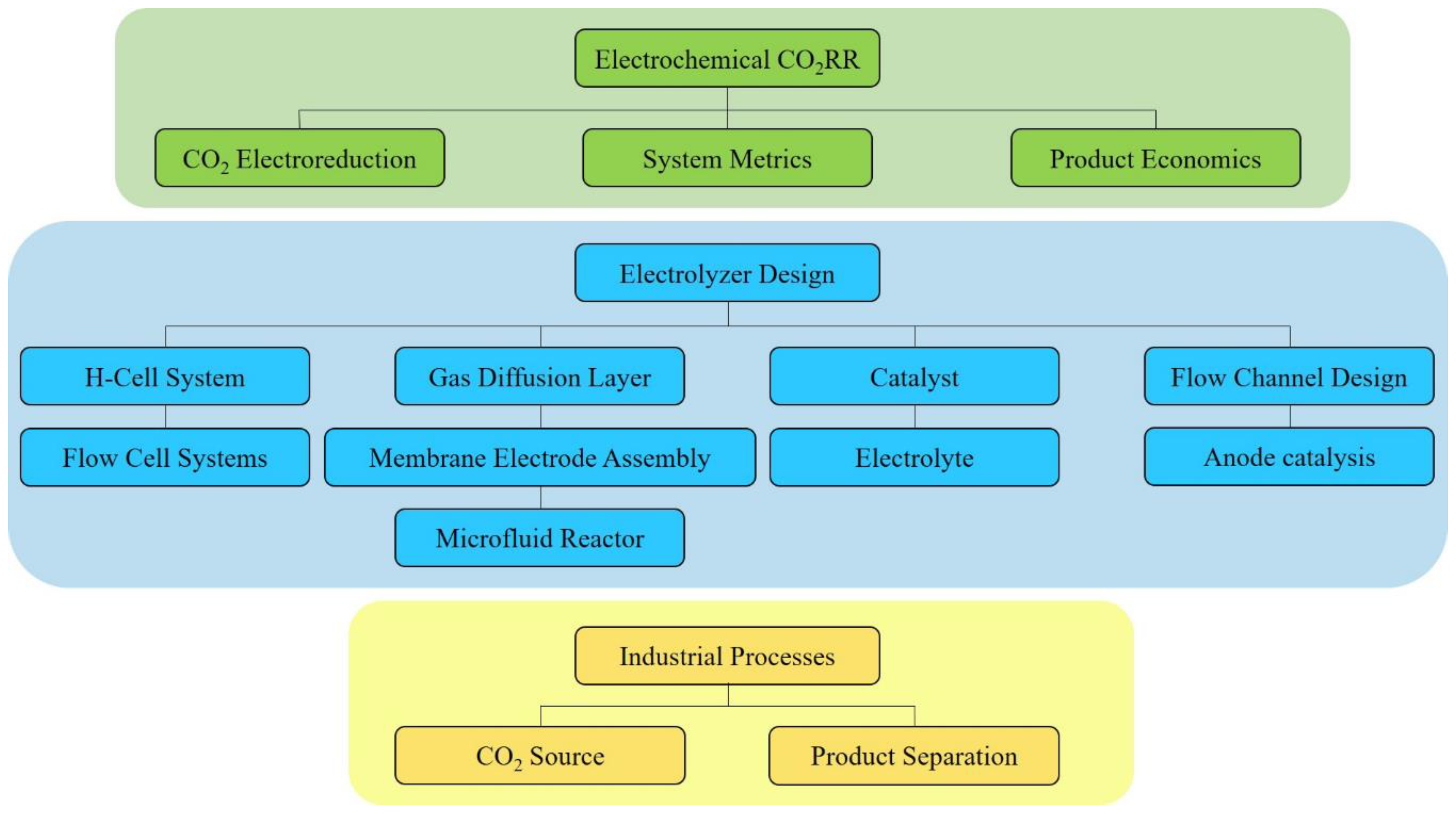
2. Electrochemical CO2RR

2.1. Carbon Dioxide Electroreduction

Electroreduction of carbon dioxide is an electrocatalytic process taking place on an electrocatalyst that is in contact with the cathodic current collector, such as a metal plate or a conducting support layer. Through a potentiostat or a galvanostat (power source), the electrons needed for the carbon dioxide molecules to undergo the reduction reaction are provided to the cathode, whereas the equal number of electrons are simultaneously drawn from the anodic reaction which is the oxygen evolution reaction (OER) in most cases. An ion exchange membrane is usually installed in the electrolyzer, dividing the cathodic and anodic chambers. The membrane acts as the means to selectively allow charge transfer, completing the electric circuit, and at the same time, as a barrier preventing other products from crossing over.
Carbon dioxide reduction reaction was discovered by Teeter and Rysselberghe in 1954 [34]. From the late 1960s to the early 1980s, CO2RR was proposed by several research groups toward the production of mainly formate, oxalate and carbon monoxide [35,36,37,38]. Since then, extensive research on CO2RR has been increasing, and different approaches with various reactor designs have given rise to multiple renewable chemical products within which some bear the potential to be scaled up and commercialized. The mechanism of CO2RR in aqueous solutions has been studied profoundly and two routes were identified: (1) CO2* (adsorbed molecule) goes through surface hydrogenation and desorbs as formate ion; (2) CO2* is transformed to CO* and either desorbs as carbon monoxide or interacts with other adsorbed species and becomes alcohols, hydrocarbons or organic acids [11].
Among these various CO2RR products reported, the most common ones (Figure 2) are carbon monoxide (CO), formic acid/formate (HCOOH or HCOO¯), methane (CH4), methanol (CH3OH), ethylene (C2H4), acetic acid/acetate (CH3COOH or CH3COO¯), ethanol (CH3CH2OH) and 1-propanol (CH3CH2CH2OH). The electron transfer in each of the mentioned products along with the main competing reaction, hydrogen evolution reaction (HER), is summarized in Table 1.

2.2. System Metrics

Regardless of the configuration, a viable CO2RR system should satisfy a few performance metrics concerning the nature of electrochemistry applicable to the reaction. These requirements include but are not limited to current density, Faradaic efficiency, overpotential, energy efficiency, catalyst activity and reactor stability.

2.2.1. Current Density

One of the most important metrics for industry-scale production is the current density, or to be more specific, the partial current density related to the desired product. This parameter effectively reflects the reaction rate of a certain product at given conditions, because the number of electrons transferred in a chemical reaction is proportional to the extent of this reaction (number of moles of reactant consumed or product formed). A higher current density in an electrochemical system indicates a higher reactant consumption rate, while a higher partial current density implies a higher generation rate of the product concerned.

2.2.2. Faradaic Efficiency

Another critical parameter is the Faradaic efficiency (FE) of the desired product. It is defined as the electric charge used for the formation of the desired product over the total charge passed between the electrodes.
F E = m n F q × 100 %
Where m is the number of moles of the desired product, n is the number of electrons required per mole of product, F is the Faradaic constant (96485 C/mol electrons) and q (or current × time) is the total charge passed between the electrodes in an experiment. Since the Faradaic efficiency represents the selectivity toward a specific product, an improvement on the FE can directly increase the amount of CO2 converted to the desired product, reduce product separation cost, and eventually lower the energy penalty of the electrocatalysis.

2.2.3. Overpotential

The overpotential (η) of an electrochemical reaction is the extra voltage needed compared to the thermodynamic prediction in order to have this reaction occur in the system. It is generally categorized into two components: the result of activation polarization (ηactivation) to overcome the activation energy barrier for reactions to occur on the catalytic electrode surface and the mass transfer limitation of dissolved CO2diffusion) [4,41]. It should be noted that the ohmic drop (iRS) across the electrolyte and ion exchange membrane would not be accounted for the overpotential but rather a potential loss that is only dictated by the ionic conductivity of the system when a current is present.

2.2.4. Energy Efficiency

Combining Faradaic efficiency and overpotential along with other losses, the energy efficiency (EE) can be derived for each species as well as across the whole cell to indicate the conversion of applied energy toward chemically stored energy.
E E = E 0 E 0 + η + i R S × F E
Where E° is the thermodynamic reaction voltage, η is the sum of the overpotentials and iRS represents the ohmic loss across the cell. The fraction in the equation is also considered as the voltage efficiency. The energy efficiency is central for the operational cost calculation and therefore becomes the most important metric for cost analysis. Only with a high Faradaic efficiency and a relatively high voltage efficiency can the EE of a system be acceptable.

2.2.5. Tafel Parameters

In a Tafel plot, the overpotential η is usually plotted against the logarithm of current density.
η = a + b l o g ( i ) = 2.303 R T α F l o g ( i 0 ) + 2.303 R T α F l o g ( i )
From the intercept of the plot, the exchange current density i0 can be obtained, which is the current density at equilibrium. The exchange current density is known as an indicator of the catalytic activity and reaction kinetics [42]. The charge transfer coefficient α can be determined from the slope. The smaller the Tafel slope, the larger the charge transfer and the more active the catalyst. A sudden change of the slope usually implies the change in reaction mechanisms due to the reaction conditions such as electrolyte concentration, reactants and catalyst surface morphology [43]. Thus, the Tafel slope can aid identifying elementary steps and rate determining steps. However, carefully distinguishing the exchange current and Tafel slopes for each product from CO2RR is required as different products result from different reaction mechanisms. To further understand this challenge, it should be noted that the obtained current density may be a summation of multiple partial current densities for production of multiple CO2RR products. Therefore, calculation of Tafel slope for products produced at lower overpotential (e.g., CO and formate) is more reliable and accurate compared to calculation of Tafel slope for products with larger overpotentials (e.g., ethylene and methane). The latter is mainly challenging due to the contribution of other products in the current density. The recommended method to calculate Tafel slopes for individual CO2RR products is thus using the partial current density instead of the total current density, which requires precise measurement of products at low concentrations. If the total current density is used for Tafel slope calculation, the attained parameters will just indicate the catalytic activity and kinetics for the CO2RR in general but not for a particular product. Overall, Tafel slope is an important parameter which can be acquired by simple electrochemical measurements and helps to understand the reaction mechanism, which will further allow faster progress in research and better reaction control in industry.

2.2.6. System Stability

System stability is the ultimate goal with respect to industrializing the electrolyzer. It is consisted of the durability of the catalyst and electrode, as well as the conditions of the electrolyte and membrane. This metric can be measured under chrono-potentiometric tests, where the current is fixed at a proper level and the resulting potential over the half-cell or full cell is recorded. If the system is robust and stable, the potential difference should be constant over thousands of hours [44]. It is obvious that by increasing the length of the stable catalysis, maintenance and the associated costs of the process can be reduced, which plays an important role in scaling up the reactor.

2.3. Product Economics

With much effort spent on advancing the novel CO2RR technology and implementing it in the industry, the production of formic acid and carbon monoxide are currently close to being commercialized. Studies on these two products have been conducted extensively and, to date, there are multiple start-ups and even established companies that have committed to providing carbon solutions and transforming energy sources from fossil fuels to clean electricity.

2.3.1. Industry Requirement

Similar to any other industrial production, the chemical production rate—or sometimes phrased throughput—for a reactor is among the top criteria to ensure profitability. This requires a higher production rate than what is currently displayed in the relative research field. As a heterogeneous catalyzed electrochemical process, the nature of CO2RR dictates that the production rate can only be boosted by the following two methods: (1) increasing the total catalyst surface area in the reactor, or, (2) increase the intrinsic reaction rate, which is indicated by the current density. The former method is certainly the necessary step for scale-up and long-term reactor design, while the latter is of greater importance since it incorporates the combined effect of catalyst activity and electrode/electrolyte engineering.
In general, the current research on CO2RR is mainly focused on the development of catalysts and the optimization of their performance. However, one of the major issues is the condition in which the optimization is carried out. As the commercial scale production requires at least 200 mA/cm2 of current density [40], the research for novel catalyst should bear in mind that this is the target and where the performance of such catalyst should be optimized upon. Most often, the profitability of a carbon dioxide conversion project heavily depends on the production cost. This draws close attention to the operational cost of the system. The biggest challenge nowadays remains to be the low energy efficiency. To have an improvement in the energy efficiency, the FE of the system should be high, while the overpotential of the electrolyzer is kept low. By having a high selectivity (FE), the process can also reduce separation costs downstream, which can be rather nonlinear depending on the desired product and its separation technique. Another direct relation to the cost is the duration of stable operation, which plays a critical role in determining the maintenance cost in a plant. The minimal stable operation duration required for profitable scaleup should be in the range of 20,000 hours [40,45].

2.3.2. Electricity and Carbon Price Considerations

The key role of electricity in the profitability of CO2RR has been discussed extensively. [4,11,40,44,46,47,48], where reports state that the cost of the electricity is the main factor in operational expenditure. As a result, locations that have a high cost associated with electricity supply may not be suitable for such industry and a change in the price can risk the profitability of the whole project. Furthermore, the source of the electricity is vital. It must be clean and renewable (i.e., solar, wind, hydro power) in order to realize the carbon neutral goal of the process. This aspect can be satisfied if the electrolyzer is located in a region with a high capacity of clean sources for electricity or utilized in a microgrid where the power supply is clean and renewable. As a result, looking at the renewable energy capacity can greatly help when deciding the plant location. As displayed in Figure 3, the generation capacity of renewable electricity varies significantly in different regions. For instance, in 2017, North America has 349 GW of total renewable electricity generation capacity, while the Middle East only has 19 GW of capacity [49]. Higher renewable capacity indicates more opportunity and larger throughput to realize this carbon neutral mandate.
With carbon tax or emission trading systems (ETS) starting to be implemented over the globe (Figure 4 [50]), more attention is paid to lowering of the carbon dioxide emissions from different economic sectors including oil and gas, transportation, building, heavy industry, agriculture and others. These policies are set to promote incentives in low-carbon and renewable energy technologies in order to achieve the climate mitigation goals [51]. Hence, the carbon-neutral power source not only ensures the carbon objective of the process but can also reduce carbon tax or increase emission trading capacity in the corporation or local government levels.

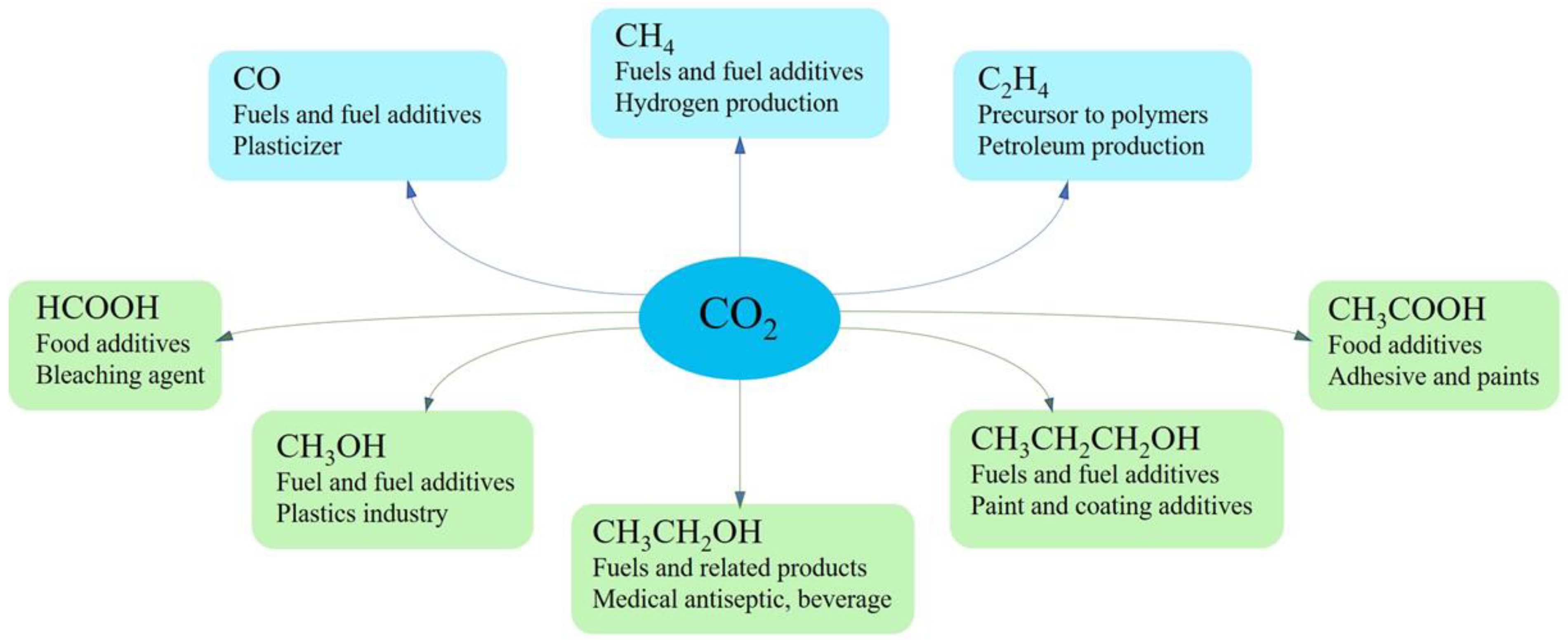
2.3.3. Feasible Products and Operating Parameters

One of the analyses that needs to be performed is a techno-economic analysis which would give a guideline on the feasible products in relation to the required operating parameters. Jouny et al. considered the end-of-life net present value (NPV) to be the criteria with which some of the most common CO2RR products are evaluated [40], although other methods that directly compare the cost of product are used as well [46,47,52]. The end-of-life NPV (in $) can be defined as the summation of the initial investment (capital expenditure) and the present value of all future cash flows till the end-of-life of the plant. In short, the NPV takes into account the time value of money and indicates whether the studied project will be feasible over its lifetime. If NPV is negative, it means the present value of all future cash flows combined is less than the capital expenditure today, then it is not considered economically viable unless there are subsidies. The NPV can be calculated as:
N P V = t = 0 n C F t ( 1 + i ) t
where, CFt is the cash flow ($) in the year t, i is the discount (interest) rate (%) and n is project lifetime (years) [53,54]. The estimation in such model is based on the material and energy balances for the process as well as estimated capital and operating expenditures. For a CO2RR plant, the capital expenditure constitutes mainly of the electrolyzer cost, the cost of product separation equipment, such as distillation columns and other supporting and auxiliary equipment (balance-of-plant). Whereas, the operating expenditure is mainly associated with the electricity cost, CO2 acquisition cost and the cost of maintenance. The variance of the end-of-life NPV of CO2RR products between two scenarios is shown in Figure 5. In the two distinct scenarios, namely, the base case and the optimistic case, the current density, cell voltage and conversion are changing variables. Whereas, the production rate (100 ton/day), lifetime of the plant (20 years), operating time (350 days/year), electricity price (0.03 $/kWh), CO2 price (40 $/ton), interest rate (10%), product selectivity (90%) and electrolyzer cost (920$/m2) remain constant [40]. The values of variable parameters for the two cases are taken based on benchmarks currently feasible and future targets. The values of current density, cell voltage and conversion for base case are 150 mA/cm2, 2.3V, 30%, respectively, whereas for optimistic case the values are 300 mA/cm2, 2V, 50%, respectively. From this analysis, the more promising products are the carbon monoxide, formic acid and propanol, while ethanol and ethylene show feasibility under optimistic conditions.
Among the various operating parameters previously discussed as system metrics, sensitivity analysis on the different CO2 reduction products shows that the selectivity and voltage are the most important electrolyzer parameters [40]. For the selectivity or FE, to which the current requirement is inversely proportional, higher selectivity would mean lower energy spent on the by-product(s), including hydrogen formation, and product separation. This in-turn would reduce the operating costs greatly. Furthermore, as the current requirement decreases, to maintain the current density, the electrolyzer area required would also decrease, thus reducing the capital expenditure. For the cell voltage, it is directly related to the power requirement so lower cell voltage would plummet the required power and further reducing the operating cost. It should also be noted that current density, which remains critical to catalyst performance, can be the least significant electrolyzer parameter beyond a threshold because the electrolyzer capital cost and current density are considered to have an inverse square relationship [40]. However, the significance of capital expenditure in comparison to operating expenditure diminishes linearly with time. As a result, it is necessary to achieve a particular threshold (200–400 mA/cm2) [40]. Increasing the current density beyond the threshold would have very little impact on the NPV so it is advisable to focus on increasing selectivity or reducing cell voltage instead.

3. Electrolyzer Design
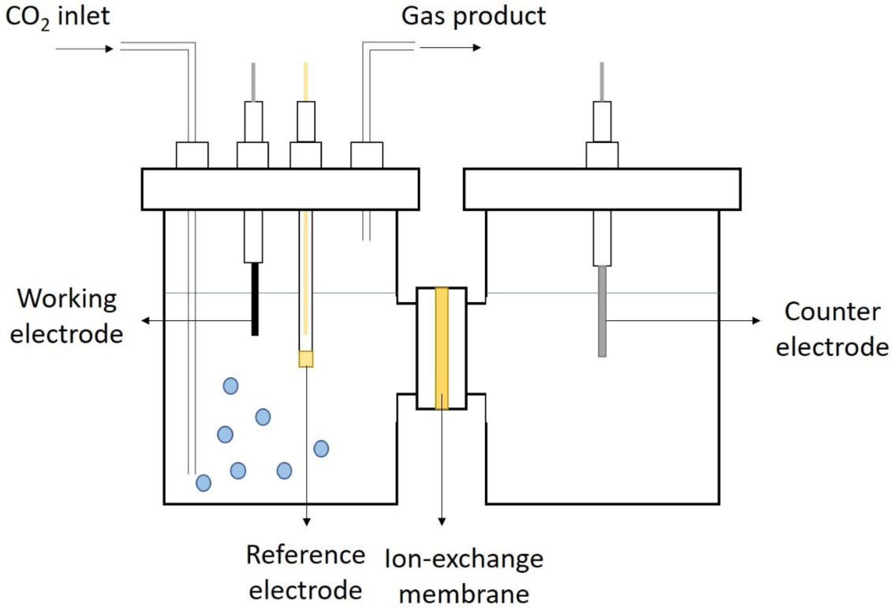
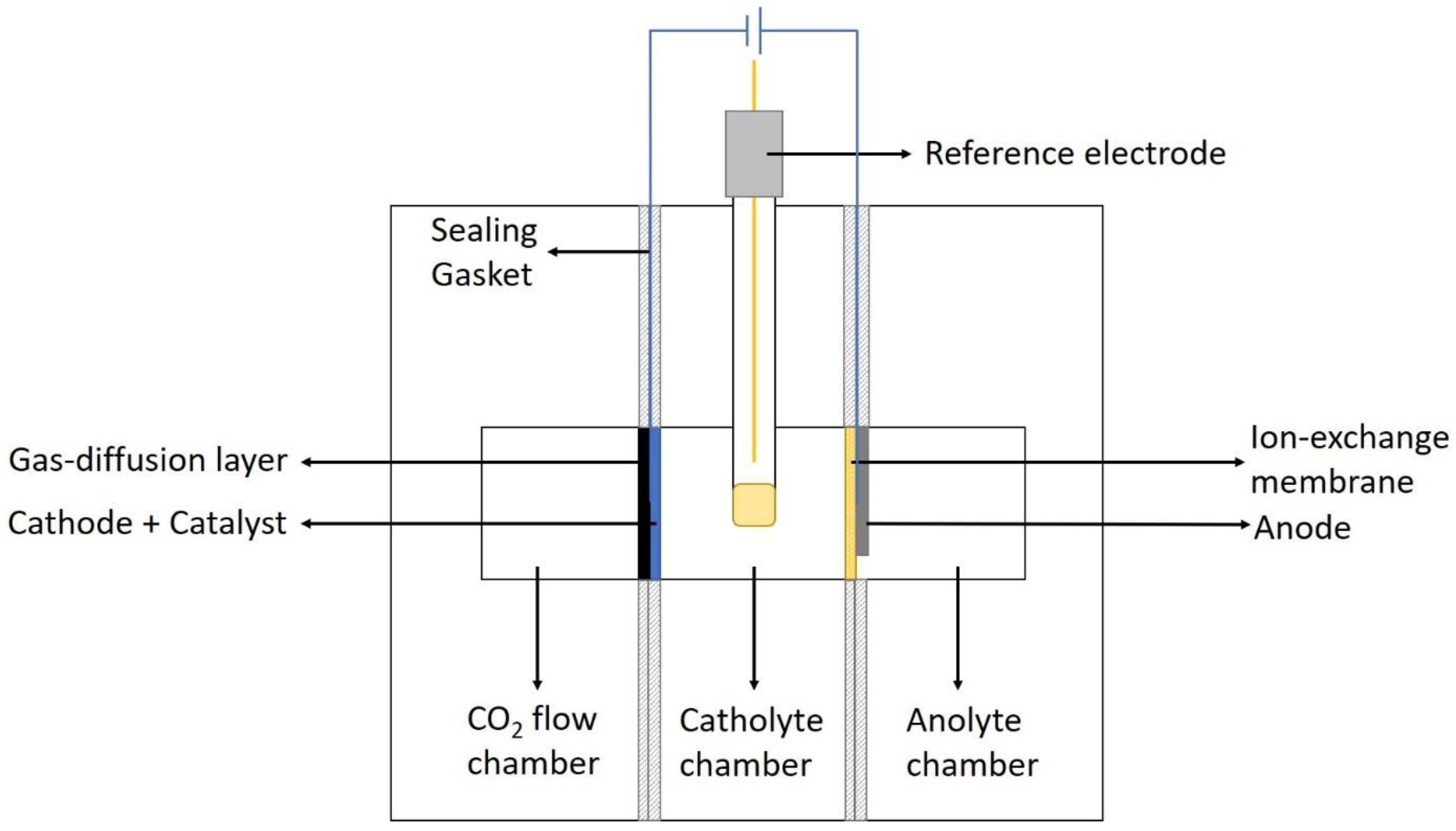
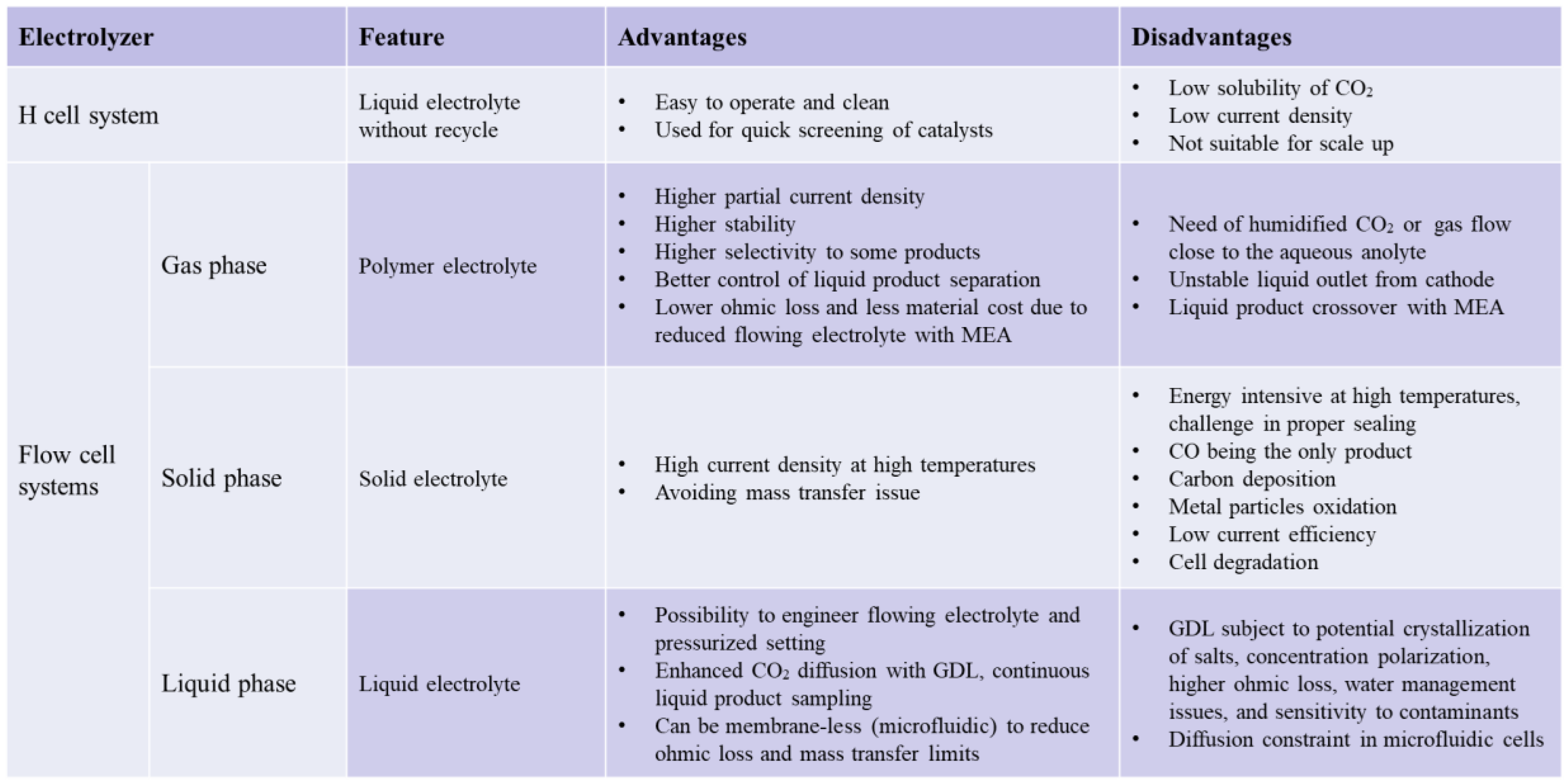
3.1. H-Cell System

Traditionally, the electrochemistry takes place in an H-type cell or an H-cell reactor, as illustrated in Figure 6. In this device, the working electrode, reference electrode and the counter electrode are fixed by the caps on the two reaction chambers, where the electrolyte is prefilled with no recycle. For CO2RR, the cathode can be a simple catalyst-deposited carbon substrate such as carbon paper or glassy carbon electrode. Carbon dioxide gas is purged into the cathode chamber and gas phase products are collected from the headspace. This type of setup is easy to operate and clean and it is used to quickly screen various catalysts. Although some successful works were carried out using this configuration [55], generally it is not suitable for scale-up because of the low solubility of the carbon dioxide gas in aqueous electrolyte, yielding a limited current density (often < 45 mA/cm2) [56,57,58]. Therefore, to meet the industry requirement, a better setup that enables higher current density and energy efficiency should be used.

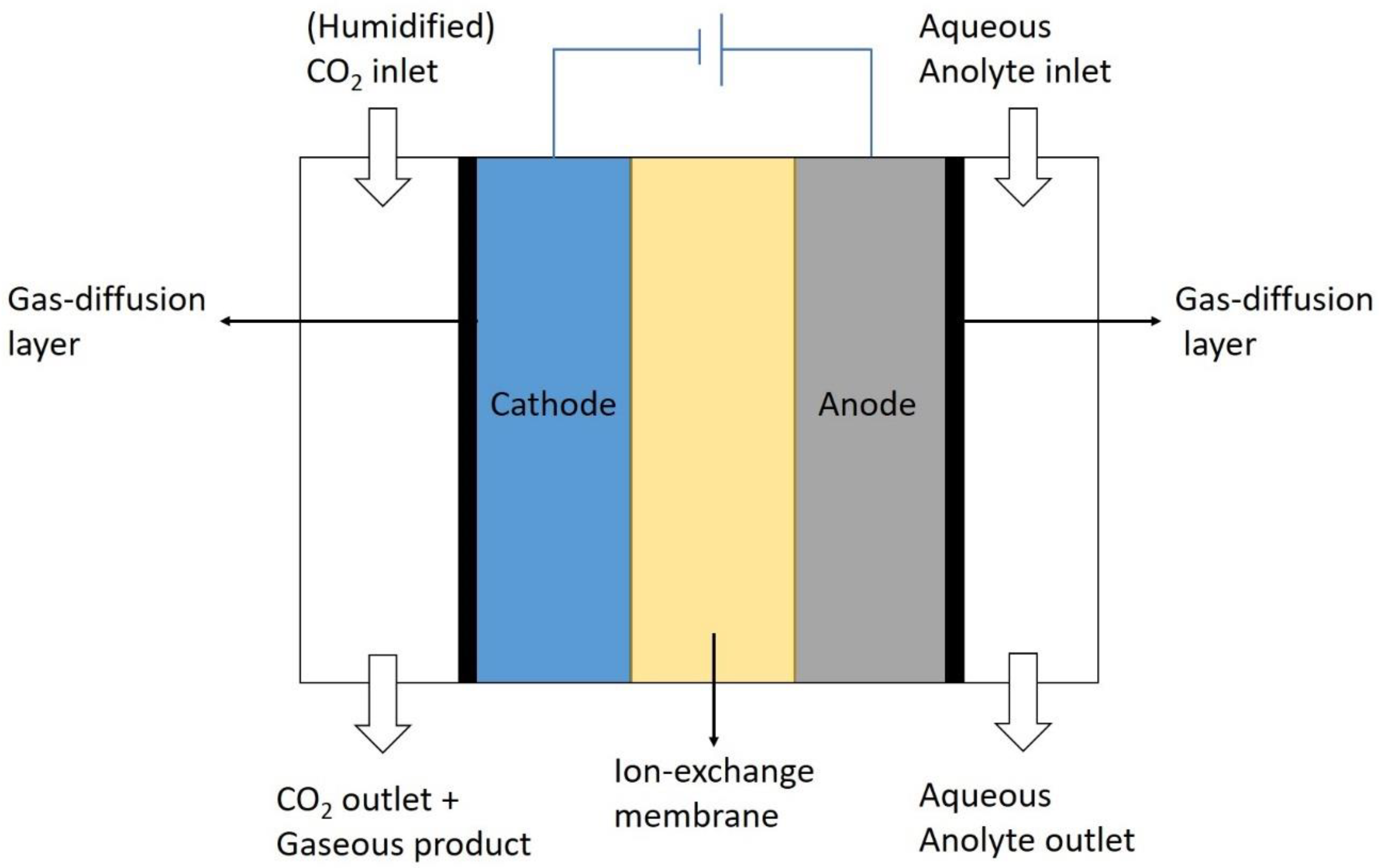
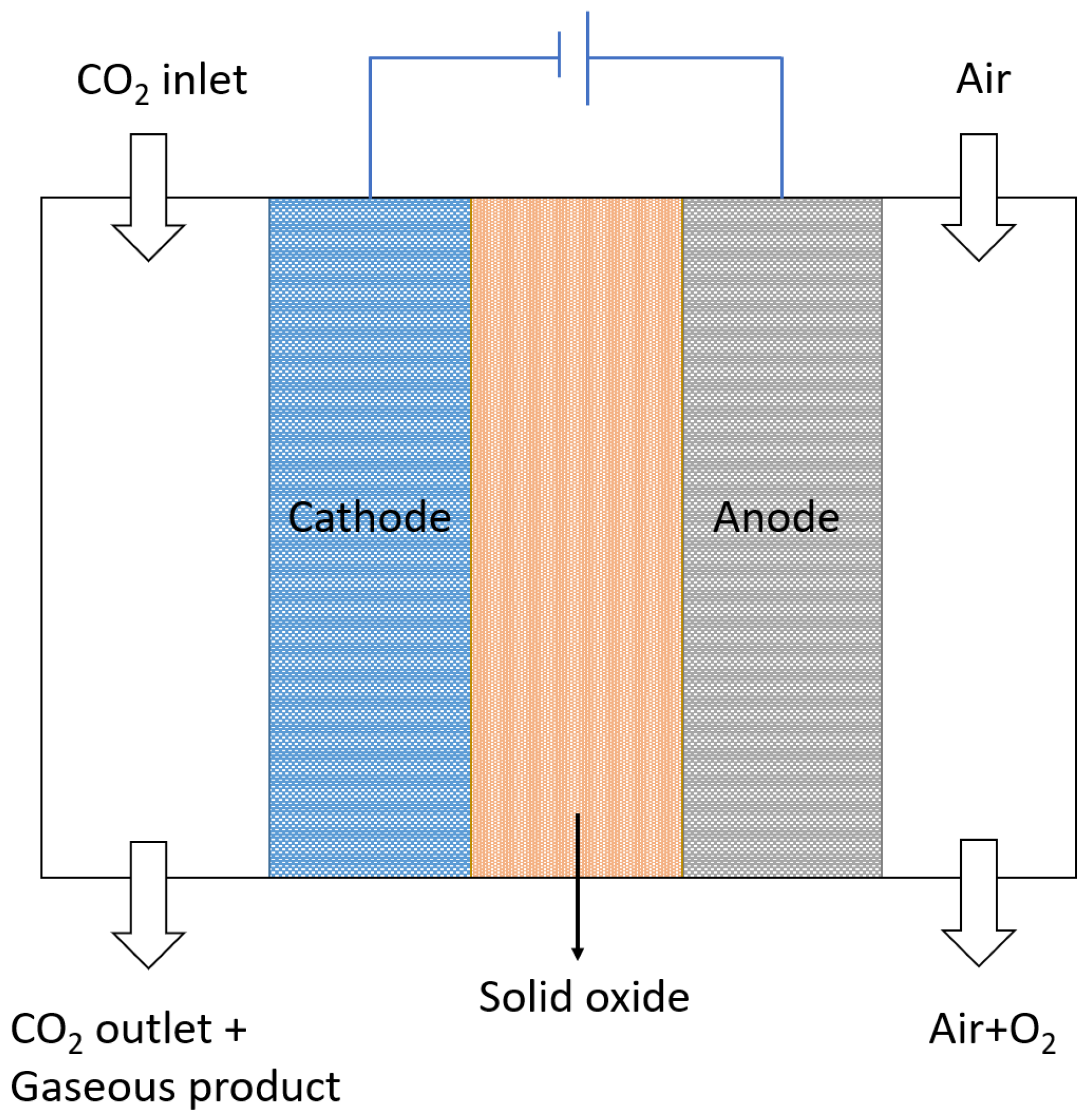
3.2. Flow Cell Systems

Inspired by the water splitting electrolyzer design, flow cell systems are developed and investigated in this application. Up to date, there are structurally three types of electrochemical flow cell systems for a CO2RR reactor: the gas phase electrolyzer, the solid phase electrolyzer and the most common liquid phase electrolyzer.

3.2.1. Gas Phase Electrolyzer

In the gas phase electrolyzer (see Figure 7), the catalyst-deposited cathode is fixed with the ion exchange membrane, forming a structure called membrane-electrode assembly (MEA). The membrane is usually a solid polymer electrolyte that can transport ionic charges from or to the cathode, enabling continuous and stable charge transfer in the circuit. This requires the cathode CO2 feed to be humidified or anolyte immediately next to the MEA to be aqueous, providing water to the cathode catalyst that allows the carbon dioxide reduction to take place. The membrane for a gas phase electrolyzer can be cation exchange membrane (CEM), anion exchange membrane (AEM) or bipolar membrane (BPM). In the case of a CEM, protons are transported from the anolyte to the cathode catalytic sites, whereas an AEM transports hydroxide (OH⁻, as the result of water electrolysis) from the cathode to the anode. A BPM combines the two types of membrane, so it simultaneously provides H⁺ to the cathode and OH⁻ to the anode. Some successful experimental results using the gas phase electrolyzer without flowing catholyte have shown improved partial current density, higher stability and better control on liquid product concentration for formate production [59] or higher selectivity on CO production [60,61]. It has also been demonstrated that alcohols [62,63,64] and other multi-carbon products [63,65,66] can be selectively produced in a gas phase electrolyzer using membrane-coated electrodes or MEAs even though the current density is low.

3.2.2. Solid Phase Electrolyzer

In the solid phase electrolyzer (Figure 8), both electrodes and the electrolyte in between are in solid form, the latter usually being a layer of solid oxide. The use of high temperature (300–600 °C) is necessary to activate CO2 reduction [67]. In typical setups, the solid electrolytes can be either oxygen-ion conducting or proton conducting. In the former case, an oxygen ionic conductor is used. It transports the oxygen ions formed in the cathode, where water molecules are reduced, to the anode where oxygen ions are oxidized to oxygen gas. Meanwhile, CO2 molecules on the cathode surface become reduced by the activated hydrogen. In the proton conducting type solid electrolyzer, the water molecules are oxidized in the anode, producing oxygen gas and protons that get passed through the protonic conductor layer and react with CO2 molecules [67]. The main benefit of the utilization of a solid phase electrolyzer is the high current density due to the enhanced kinetics at high temperatures [68]. It can also avoid the mass transfer issue of dissolved CO2 in most liquid phase electrolyzers [67]. However, there are several drawbacks due to high temperature, including the challenge in proper sealing, CO as the only reduced carbon product, carbon deposition, metal particles oxidation, low current efficiency and cell degradation [67,69], which require more sophisticated research before this is accepted in the industry.

3.2.3. Liquid Phase Electrolyzer

Most commonly used in the electrocatalysis of carbon dioxide is the liquid phase electrolyzer, as shown in Figure 9. The main characteristics of this type of reactor are the presence of liquid electrolyte in both electrodes, commonly with a gas diffusion layer (GDL) on both electrodes and an ion exchange membrane in the electrolyte bulk. Similar to the gas phase electrolyzer, the membrane serves the purpose to transport ionic charges between the electrodes. Depending on the types of the membrane (CEM, AEM or BPM), the corresponding charged ions are passed to the electrolyte and therefore complete the circuit. The distinctive feature in this kind of system from the earlier mentioned gas phase electrolyzer is the possibility to engineer flowing catholyte. As a result of the presence of the liquid catholyte, CO2 inlet to the cell does not need to be humidified and can be utilized in a pressurized setting [70].

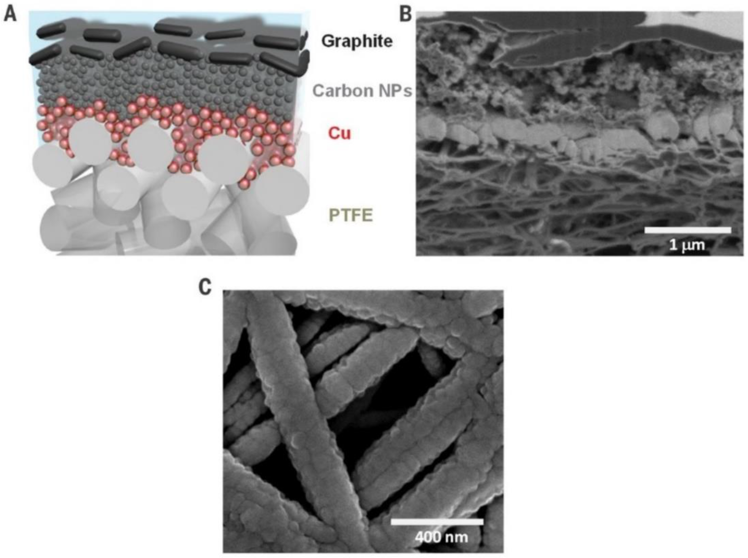
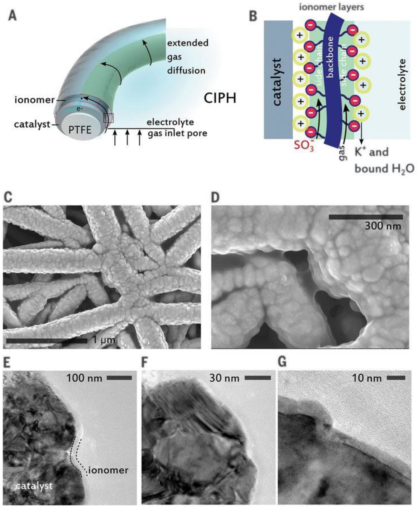
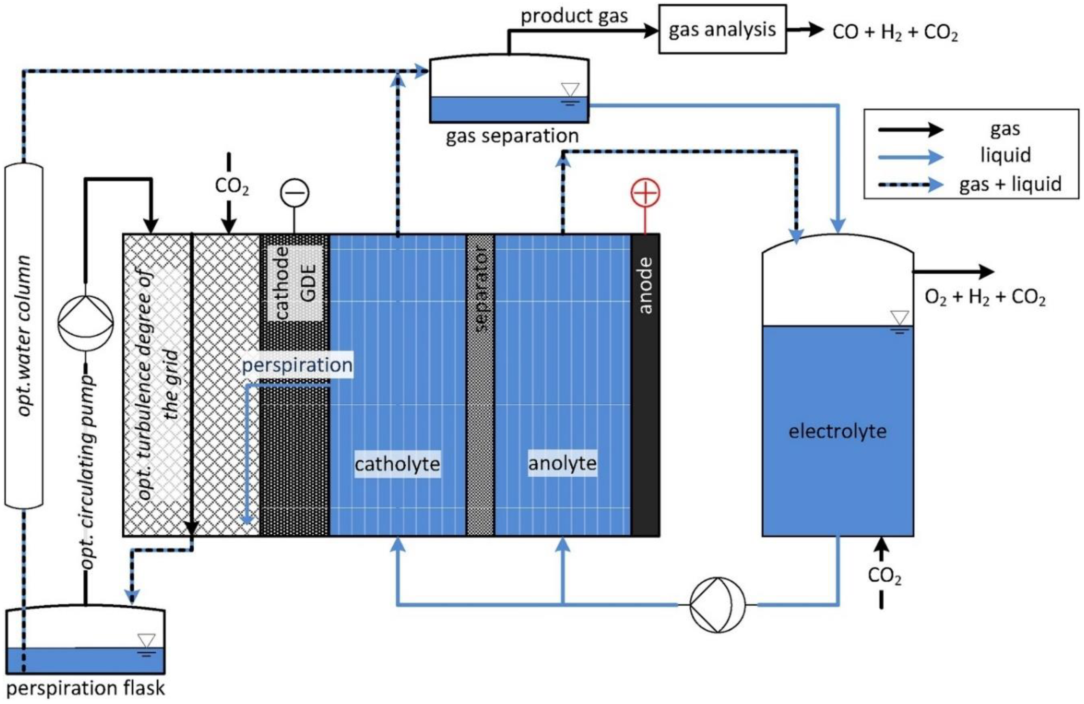
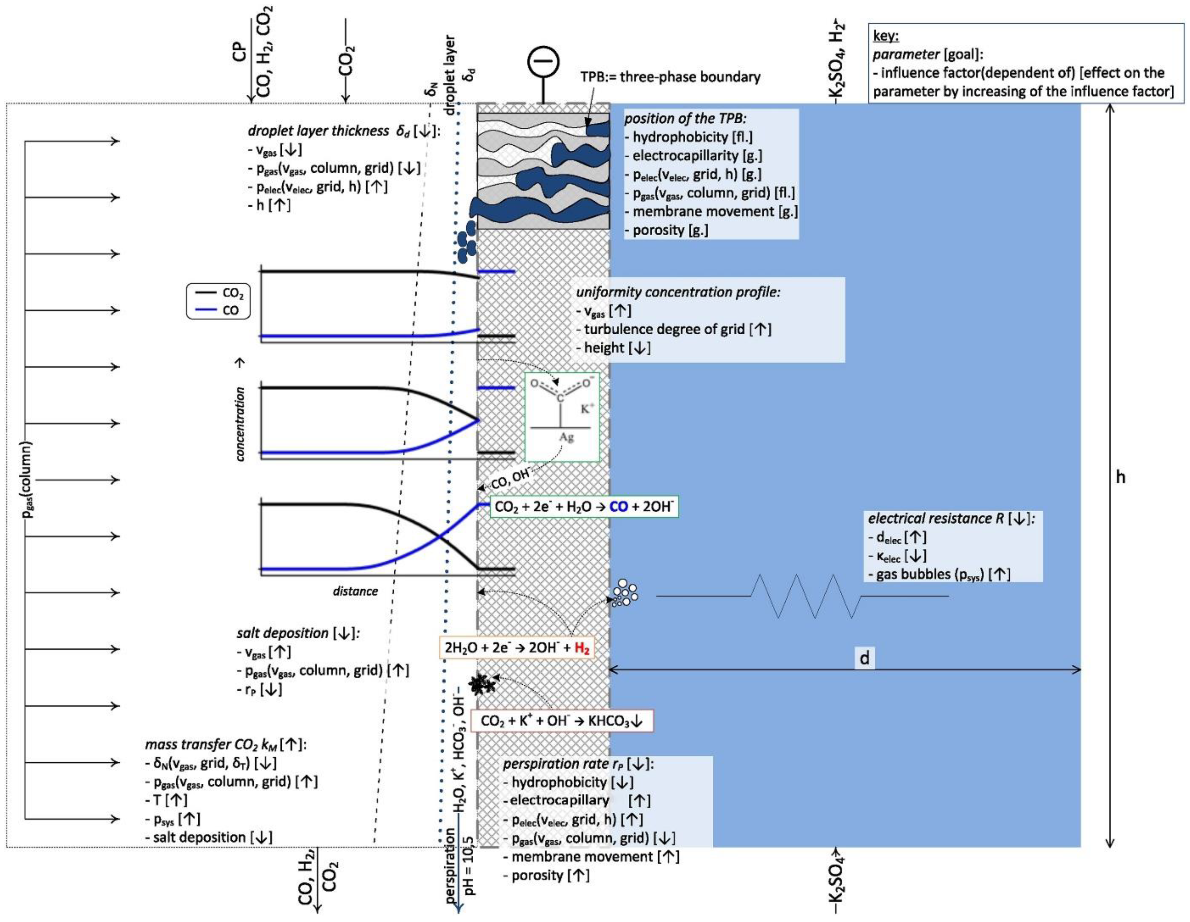
3.3. Gas Diffusion Layer

Gas diffusion layer (GDL) was developed historically for fuel cells [71,72,73] and water electrolyzers [45,74], and it is a means to provide triple phase boundary of carbon dioxide gas, catalyst surface and electrolyte [45]. However, it was shown that without the presence of water content, the reaction conversion is poor [75,76,77,78]. Further studies have proposed that due to the wetting characteristics of the catalytic surface under negative potentials [79], CO2RR is still occurring in the aqueous phase with CO2 in dissolved fashion [57,80]. This postulate should be more closely examined with computational revelation and in situ experimental confirmation.
In a typical H-cell setup, prior to the electrochemical experiment, carbon dioxide needs to be dissolved from gas purging in the bulk electrolyte until the solution is saturated [81]. When CO2RR occurs, all products are leaving the surface in the opposite direction of incoming dissolved CO2. On the contrary, in the case of a gas diffusion electrode (GDE) with a GDL, the liquid products remain in the aqueous phase due to the hydrophobicity of the GDL, and only the gaseous products leave from the gas side of the surface. Compared to the traditional H-cell configuration, the main benefits of the use of a gas diffusion layer on the electrode are linked to its better mass transfer characteristics and shorter diffusion path [82]. It was discovered that the diffusion path for dissolved CO2 from the bulk to a non-permeable catalytic electrode surface is in the proximity of 50 microns whereas the diffusion distance from the gaseous CO2 to the liquid surrounded catalyst surface is only about 50 nanometers [57,80]. Due to this unique phenomenon, two significant benefits arise. First, the shorter diffusion path ensures the CO2-saturated electrolyte layer on the catalyst, which was shown to prevent HER [83]. Second, the CO2 gas can get to the active sites much faster before it gets reacted with the hydroxide in the electrolyte, hence allowing the use of alkaline electrolytes [84].
Another unique characteristic of GDL is the reaction direction of carbon dioxide. On an H-cell electrode, the CO2 is approaching the catalyst surface from the bulk while on a GDL, the reactant gas is purged through the hydrophobic layer on the support, which prevents the gaseous products agglomerating and blocking catalyst surface and in the meantime facilitates the adsorption of incoming CO2 [85]. Therefore, the implementation of a GDL simultaneously solves the issues of mass transfer limitations and the availability of CO2 at the liquid-catalyst interface. As a result of the improved CO2 concentration at the surface of the catalyst, the designed morphology and surface area of the catalyst can result in better activity, lower overall cell potentials and perform more closely to the research intention [85]. Due to these important benefits, the use of gas diffusion layer is strongly recommended if the process is to be scaled up in this setup [32,57,85,86].
There are also challenges related to the GDL in electrolysis, especially at a high current density. It is subject to potential crystallization of hydroxide and bicarbonate salts in the porous layer of the GDL, because of the increase hydroxide formation on cathode [85]. At current densities higher than 50 mA/cm2, the local pH is shifted to 12 and above, resulting in a different local environment for CO2RR as opposed to the bulk, which needs to be properly addressed such that the catalyst designed is not optimized under unexpected reaction conditions [57,85]. In operation aspects, several points should be noted. First of all, the ohmic loss iRS will be higher because the current is higher. In addition, the electrolyte pH, temperature of the electrodes and charge conductivity may be changed overtime due to concentration polarization between the two electrodes [85]. In addition, the pressure between the two phases is crucial in reaction local environment as well. To maintain the ideally wetted surface on the catalyst remains one of the most practical challenges for CO2 electrolyzers, which is also known as water management on the GDE [87].
Due to the nanostructure of the hydrophobic layer, contaminants in the electrolyte are detrimental to the active sites on the catalyst surface, precautions and protection of the electrode should be carefully considered when GDE is used. To overcome the instability of GDE, Dinh et al. have reported a robust design where the catalyst is sputtered on a porous layer of PTFE and nanoparticle carbon is spray-coated on top of the catalyst layer, stabilizing the copper catalytic layer in potassium hydroxide (KOH) solution (Figure 10) [82,84]. García de Arquer and coworkers recently achieved a partial current density of 1.3 A/cm2 toward ethylene production using just a thin film of Nafion® ionomer on the catalyst without any carbon or graphene layers, which they called catalyst:ionomer bulk heterojunction (Figure 11) [88]. Such architecture, according to the authors, can extend the CO2 gas diffusion zone along the catalyst surface, thus promotes more CO2 conversion and higher current density.

3.4. Membrane Electrode Assembly

With many limitations in traditional H-cell configuration, gas phase electrolyzers were also developed to account for better mass transfer and lower cell potential. Similar to liquid phase electrolyzers, the reaction takes place in the three-phase region on the catalyst rather than the liquid bulk. This again ensures a sufficient concentration of carbon dioxide at the catalytic surface. What differentiates an MEA type of electrolyzer from a GDE liquid phase electrolyzer is the lack of liquid electrolyte in the cathode. As shown in Figure 7, the membrane is placed or even bound directly on the electrode. The other side of the electrode is then covered by a layer of gas diffusion porous medium.
The most common type of membrane used in the MEA setup is the proton exchange membrane with a perfluorosulfonic acid (PFSA) basis such as Nafion® [59,63,64,65,66,75,77], which transports protons from the electrolyte in the counter electrode to the adsorbed CO2 molecules. Studies also show promising results using AEM in the assembly [60,89,90,91], where membranes with imidazolium on styrene backbone can both increase the CO selectivity and current density with considerable durability [60]. Li et al. [92] have shown that by using a bipolar membrane in the MEA, pH control on both electrodes can be realized, while current density, overpotential and stability are also achieved with a better standard than other membranes.
A typical electrolyzer structural design using MEA consists of an anode chamber with liquid phase anolyte and a cathode chamber with only gas phase inlet. An alternative type of electrolyzer has also been developed in which the anode and cathode are both electrolyte-free. In this electrolyte-free (or “zero-gap”) setting, the anode feed is humidified hydrogen gas [77,89].
MEA excels at reducing the use of flowing electrolyte thus lowering ohmic loss while the GDE eliminates the concentration polarization in the bulk electrolyte which occurs in H-cells. It also avoids the high temperature startup and operation required in a solid electrolyzer. However, there are also challenges to be overcome. The first problem in MEA setup is the water management on the cathode catalysis surface. One simple way to solve this is to use properly humidified CO2 as the feed. However, even with the humidification, membrane can turn dry in an experiment, so anolyte is still needed to ensure water supply to the cathode catalyst [60]. In addition, the liquid products generated by CO2RR face the challenge to be separated and collected on the industrial scale. This is because most often the liquid products are collected from the cold trap on the cathode outlet [63,65,66,75,90]. In this fashion, the liquid production is hardly constant over time and thus can only be processed in a batch mode. Another issue associated with the liquid products is the crossover from cathode and re-oxidation at anode. In many assemblies with AEM or even Nafion®, charged aqueous products such as formate, acetate and small molecules like methanol can be easily transported from cathode to anode [93]. Then at anodic OER potential, these products can be oxidized which would release CO2 back to the atmosphere [78,91].
In summary, using a membrane electrode assembly in a CO2RR electrolyzer can benefit from lowered material costs, reduced cell potential as well as enhanced CO2 mass transfer. Challenges in such setup remain in aspects including water management on cathode surface, scale-up difficulties in liquid product collection and crossover of liquid products to the anode.

3.5. Microfluidic Reactor

To further decrease the cell potential while alleviating mass transfer limitation, membrane-less electrolyzers with GDL were developed and stand as an alternative in commercializing CO2RR. This type of electrolyzer is called the microfluidic reactor, emphasizing the thin layer of electrolyte between cathode and anode. This setup exploits the benefit of laminar flow of the electrolyte which then can reduce mixing and thereby neglecting the use of membrane in the cell [94,95]. The design of the flowing electrolyte allows tailoring of the pH and temperature of the reaction environment which would be considered limited by the presence of membrane [96,97]. This feature also enables continuous liquid product sampling and analysis just like other liquid phase flow cells [96].
Challenges related to the microfluidic reactors reside in the design of electrolyte flow. If the electrolyte is flowing in one channel, there can be crossover from cathode to anode which will result in oxidation of formic acid, methanol or other liquid products. To mitigate this problem, some design can be considered when utilizing such electrolyzers, including nanoporous separator or multichannel design [98] and dual-electrolyte system [94]. These modifications, or variations of microfluidic cells face an important issue of diffusion constraint in the liquid phase due to the absence of a semi-permeable membrane. After a certain length along the flow axis, the diffusion zone for the cathodic product layer gets wider and will eventually meet the anode GDL. This certainly depends on the flow rate and the specific channel design, but with a minuscule flow depth, it yields a small characteristic length in diffusion direction, giving rise to difficulty in scaleup of the reactor.
Up to this point, a brief summary on the structural design of CO2RR electrolyzers is shown in Figure 12.

3.6. Catalyst

In any CO2RR reactor, catalyst plays a critical role when certain groups of products are being targeted. Common catalysts include metal-based catalysts such as Cu, Au, Ag, Sn, Bi and non-metal elements such as graphene and carbon nanotube (CNT). The selection of catalyst directly defines the possible reaction pathway and intermediate energy states. Generally, catalysts can be deposited, spray-coated, drop-casted, electrodeposited onto a substrate or directly used as the electrode in the case of an H-cell.

3.6.1. CO Production

Since CO is the simplest gaseous product from CO2 reduction with only two electrons transferred, the process has been heavily studied and several elements have been reported to have superb selectivity toward the diatomic molecule. It is noticed that gold, silver and sometimes bismuth are excellent at converting CO2 to CO with high selectivity. AuFe core-shell nanoparticles have shown a mass activity of 48.2 mA/mg for CO production along with near unity selectivity and 90 h stability [99]. Size-dependent catalytic activity was also studied on micelle-synthesized Au nanoparticles and a drastic increase in activity was found in size range below 2 nm for electroreduction of CO2 to CO [100]. More commonly, Ag is used as the catalyst for CO2 to CO conversion and there are various methods in synthesis of the catalyst or electrode material. For Ag nanoparticles, when switch from conventional carbon support to TiO2 support, Faradaic efficiency of 90% and current density of 101 mA/cm2 can be reached [101]. By incorporating a mixed layer of multi-walled carbon nanotubes and the Ag catalyst, the charge transfer resistance can be decreased, resulting in a much-improved current density (350 mA/cm2 at −0.8 VRHE) [102]. Organometallic silver catalysts have also been developed to demonstrate 90% selectivity and 95 mA/cm2 current density [103]. Dinh et al. fabricated their silver catalyst by using a sputtering system and adding a carbon nanoparticle layer, which then showed an overall performance in CO production with over 90% FE, 150 mA/cm2 and for over 100 h of operation [82]. Some recent research has presented novel Ag-GDE catalyst by direct synthesis through metal-organic framework (MOF)-mediated approach, which can maximize the metal catalyst activity toward 1864 mA/mgAg (silver loading of 0.2 mg/cm2 and CO partial current density of 385 mA/cm2) [104]. In addition to the common Au and Ag related precious metals, Bi-based material in combination with ionic liquids can also catalyze CO production from CO2 with EE of ~80% or selectivity of 85%–87% [105,106]. Recent studies also demonstrated the possibility of CO production via non-precious metals such as Bi, Pb, Sn and Ni [107,108]. One of the most impressive studies from Kutz and coworkers shows the possibility of using Ag nanoparticles in an MEA to convert CO2 to CO at 200 mA/cm2 with 1000 h stability [60].
In summary, CO as a CO2RR product has undergone a massive amount of research where most promising results are from the utilization of gold and silver, while a transition toward earth-abundant metals has also been seen recently. In spite of the achievement in CO production, challenges remain. Zhao and coworkers have pointed out that surface engineering and morphology control is critical in improving the Faradaic efficiency and minimizing the overpotential [109]. Referring to the industry requirement of 200 mA/cm2 current density, even though CO is the product closest to commercialization, more stability experiments at the relevant conditions on different catalysts and a thorough life cycle analysis (LCA) are still lacking. Therefore, future work should focus on the design and control of the catalyst surface for production of carbon monoxide while understanding the effect of solvent molecules interaction at the interface under high current is equally important.

3.6.2. Formic Acid Production

Formic acid is an interesting chemical product that is widely consumed by the animal feed industry and textile industry, with a global market nearing 878.7 million U.S. dollars [110]. Compared to multi-carbon products, the formation of formic acid is relatively straight-forward, and p-block metals are common catalysts for this reaction [111,112,113,114]. Among these catalysts, Bi has garnered interest due to its low toxicity, relative availability and high selectivity towards formate production. According to DFT studies, Bi electrode surfaces have demonstrably higher free energies of hydrogen adsorption, thus leading to decreases in HER catalytic activities hence higher CHOO selectivity [115]. The excellent properties of Bi electrodes have been demonstrated in many past works: Han et al. had synthesized Bi nanosheet electrodes with F.E. close to 100% at −1.3V vs. SCE [116]; meanwhile, work from Wang et al. with bismuth oxyiodides has demonstrated high current densities (40 mA/cm2) at −0.9V vs. RHE while maintaining high FE [117]. The continued development of Bi-based catalysts is ongoing and the adoption of some catalyst fabrication techniques to Bi may be promising.
It is widely recognized that the use of alloys, instead of pure metal catalysts can better tune the catalyst’s surface electronics, thus optimizing the catalytic properties; this method has been adopted for the combination of many p-block metals with each other or with transition metals. For example, Sn/Pb alloy has been demonstrated to have 79.8% FE toward formate [118], while Sn/Cu alloys have reached 95% FE [81]. There have been studies conducted on noble metal catalysts such as Sn/Au alloy, but its Faradaic efficiency and overpotential were inferior to many non-noble metals counterparts previously reported [119]. The prospect of using noble metal catalyst becomes more enticing when low overpotential can be achieved, such as a Pd nanoparticle catalyst reported to reach 97% FE at −0.2V vs. RHE [120]. However, from the same study, it was shown that Pd catalysts are prone to CO poisoning, which limits the stability of the system. Attempts have been made to mitigate Pd instability through surface modifications, but the results do not satisfy the range of preferred stability recommending in techno-economic analyses, generally in hundreds of hours. There have also been forays into non-metallic materials in the search of a more stable catalyst, such as boron-doped diamond catalyst which has shown promising FE ~90% for a period of 24 h, but the reported current density is lower than Sn or Pb electrodes [121].
Alternatively, another promising group of catalysts combine carbon support along with p-block metal to form the catalyst. For example, a class of nanocrystalline carbon support called graphene nano-flakes (GNF) has been previously developed, which exhibits stability enhancement effects and can be functionalized and decorated with nanoparticles [122]. Previous studies have experimented with combining this material with copper nanoparticles, producing a catalyst that produces formate, albeit at low selectivity. But ongoing investigations are exploring the prospect of using p-block metals and other metal oxide, sulfide compositions.

3.6.3. Multi-Carbon Production

Cu is a unique catalyst for CO2RR reaction. It has the potential to produce 16 products [123], including many multi-carbon products [124,125,126]. Cu surface modification remains an active area of research. Techniques including oxide derived (OD) Cu, electrodeposition, nanoparticle (NP) deposition, bimetallic combination, etc. were tested in the past few years to tune the selectivity, improve current density and stability. Stability is also an important test parameter when a new catalyst is developed. Cu alloys with Zn, Cd, Ag, Sn, Pb, Ni, Bi, Pd, etc. were synthesized to stabilize the Cu NPs and tune the CO2 RR product species [127]. The bimetallic structure can be applied to both H-cells and flow cells. More tests with bimetallic catalysts can be run to discover the effect of alloy structure.
OD Cu foils are often tested in the H-cell setup. Metals such as Au and stainless steel are used as the support for electrodeposition to create various nanostructures like nanofoams and nanocrystals [128]. These substrates not only provide conductivity to complete the circuit, but also have the advantage that deposition potential on a foreign substrate is often higher than that on the same metal because of the crystallographic substrate-metal misfit. [129] However, it is still hard to reach a current density higher than 45 mA/cm2 in H-cells, so H-cells are only suitable for lab scale research. While in liquid phase flow cells, various GDL were used for Cu particle deposition, some based on carbon fibers such as Sigracet® and Freudenberg® and other based on hydrophobic polymers such polytetrafluoroethylene (PTFE). The catalyst layer should also be porous to allow access to CO2 flow from one side and electrolyte from the other side, instead of the planar geometry in H-cells. The Cu catalysts on the GDL have better access to CO2 due to more surface area and short gas diffusion distance, which contribute to higher current density [130]. More effort should be spent on developing catalysts in the flow cell since it has the potential to achieve the desired current density for commercial scale production. The higher local pH value in flow cells as mentioned before, could help the performance of CO2RR. However, the accumulation of OH near the catalyst could form crystals such as Cu(OH)2 and change the catalyst performance.
Beside Cu-based catalysts, various experiments also shed light on the possibility to produce C2+ with non-metal catalysts such as B-N-co-doped carbon structures [131], graphene quantum dots [132,133], Cu-based metal-organic frameworks [134] and carbon nanotubes [65]. However, most surface modification methods, including metallic or carbon-based structures, are very energy intensive. Further LCA should be done on the catalyst to ensure the whole process is carbon negative or at least carbon neutral. A balance needs to be found in the future between catalyst performance and energy consumption during the synthesis process.

3.7. Electrolyte

The impact of the electrolyte is generally well understood thanks to the previous electrochemistry advancement. The general requirement for a feasible electrolyte can be summarized to the three properties that it should bear: good ionic conductivity, stable pH in bulk and moderate to high CO2 solubility [85]. Two distinct types of electrolyte have been developed by now, which are the aqueous electrolytes and ionic liquids [135]. The most common aqueous electrolytes in the research realm nowadays are families of sulfates [136], chlorides [137], bicarbonates [75,91] and hydroxides [70,83]. In more detailed study on the hydration effects, bicarbonates and hydroxides which create an alkaline environment are shown to be better suited in production of CO [82], formate [136] and C2+ products [84,138,139].

3.7.1. Alkaline Solution

One of the most common electrolytes is alkaline solution, after it was discovered to bear lower overpotential than its neutral counterpart [57,140]. Its high alkalinity in electrolyte is shown to be suppressive on HER and thus beneficial toward multiple CO2RR products [70,82,84]. Specifically, in alkaline conditions, without many protons available to the catalyst surface, the hydrogen evolution reaction is sufficiently limited, whereas CO2 is open to more active sites, therefore lowering applied potential and improving Faradaic efficiency [70,140,141,142,143].
In production of CO from CO2, it was reported by Verma and coworkers that the use of 2 M KOH as electrolyte can promote activity of CO2RR, reaching a partial current density of 99 mA/cm2 toward CO with a cathode overpotential of 0.02V [144]. Elevated concentration of KOH has also been investigated and its positive effect on product yield was also discussed [70,141]. It was demonstrated by Verma et al. that the anion effect of hydroxide on the double layer formed on the electrode surface can lead to better stability of CO2RR intermediates and reduce the likelihood of HER compared to bicarbonate and chloride [141]. By adding traces of halides to the electrolyte, experiments have shown that these anions can improve CO selectivity, modify surface morphology and promote protonation of the adsorbed species [145]. With this technique, current density of ethylene production is largely increased [84].
Another electrolyte, potassium bicarbonate (KHCO3), is widely used in this field of study because of its CO2 affinity and inexpensiveness [38,146,147]. However, lower conductivity of KHCO3 solutions can be a shortcoming which leads to higher cell potential or lower current density, compromising the energy efficiency of the electrocatalysis [11,141,148]. Moreover, a disadvantage for buffer solutions such as KHCO3 is the favor of proton transport, which as a result promotes H2 and CH4 formation instead of C2+ products such as ethylene [149,150,151]. Verma et al. also found smaller overpotentials and lower impedance using KOH versus KHCO3 as electrolytes for CO production [141].
Different choices for electrolyte are considered to be determinant due to also some hydrated cations effects known to the CO2RR process [152,153]. The cation effect is studied, and evidence shows the preference to CO production on silver surface is facilitated by larger cations such as K+, Ru+ and Cs+ [154]. Recent density functional theory (DFT) computation-guided experimental results show that the lack of hydronium near Ag catalytic surface can promote formate yield if the electrolyte is overall alkaline [83]. From CO2RR to ethylene on Cu electrocatalyst, the same overpotential shift toward more positive values with the use of concentrated KOH is again observed [84].
However, there is a persisting issue of CO2 uptake because of the hydroxide reacting with the dissolved carbon dioxide [155], which changes the electrolyte content and conductivity overtime thus jeopardizes the electrode durability. To realize the goal of stable and sustainable operation, engineering solutions are urgently needed. Challenges accompanied with the high local concentration of OH- include the surface reconstruction that allows irreversible binding of CObridge that is unreactive under reduction potentials [156], as well as water management [87] and mass and charge transfer modeling at the gas-catalyst-electrolyte interface [157,158].

3.7.2. Pressure and Temperature Effects

Generally higher pressure of the operating electrolyzer can help increase the adsorption of CO2 species on the catalytic surface because of the increased concentration of CO2 in the gas channel and in the liquid electrolyte. Earlier works have shown an increase in current density by increasing CO2 partial pressure on Co, Fe, Cu, Pb, Hg, In and other catalysts [159,160]. Dufek and coworkers experimented at 18.5 atm and 90 °C where they observed lowered cell potential (below 3.0 V) at applied current density of 225 mA/cm2 with above 80% FE toward CO on Ag-based catalyst and 50% EE [161]. According to Gabardo et al., a pressurized (7 atm) flow cell reactor combined with the use of high concentration KOH solution (7 M) as electrolyte can greatly improve the half-cell energy efficiency to 81.5% at an industry-relevant current density of 300 mA/cm2 [70]. However, the water management and GDL maintenance should be carefully handled in higher pressure systems. Unbalanced pressure across the GDL can result in either flooding of the catholyte or drying of the catalyst surface which can prevent the cell from normal operation [162].
For a liquid phase system, most of the studies using a GDE were conducted at ambient temperature, and the effect of temperature on the reaction has rarely been studied. Löwe et al. have shown that the optimal temperature in alkaline condition (pH = 10) for formate production on tin oxide loaded GDE was 50 °C [86]. It was reported to be the balance of electrode activity and the carbon dioxide solubility, where the former increases steadily with temperature and the latter decreases at higher temperatures. With lower temperatures, CH4 was found to be the major product on polycrystalline Cu surface [163]. If the temperature is increased, CO2 solubility is lowered, as a result HER will become the dominant reaction instead of CO2RR. In addition to the solubility limitation on temperature, AEM and aqueous electrolyte are also limiting the upper bound of operation temperature to be about 80 °C due to membrane performance and safety concerns. Therefore, the operation window for temperature on a liquid electrolyzer is rather narrow, unless it is combined with pressurized system as discussed above.
In the case of a gas phase electrolyzer however, Lee and coworkers have shown that increasing the temperature to 363 K (90 °C) can improve the partial current density of formate more than twofold (52.9 mA/cm2 at 363 K) on tin nanoparticles catalyst [59]. It was reported that by constantly supplying water vapor with CO2 into the cathode, the solubility issue of carbon dioxide in liquid could be overcome. Then with higher temperature, the kinetics of CO2RR can be accelerated, yielding a higher selectivity in formate. This setup was also limited by the membrane used. At 363 K, the swelling of membrane took place, where water was crossing over from anodic electrolyte to the cathode [59]. This indicates a small operation window again for gas phase electrolyzer, but further study is needed to investigate the reaction mechanism at elevated temperature.
In short, few studies so far have systematically researched on the pressure and temperature effects. From limited number of papers, a hypothesis can be postulated that pressures and temperatures that are slightly higher than ambient conditions could be helpful toward product selectivity and reaction rate. Further study on temperature effects on electrolyzer performance is needed, regarding different classes of catalysts and products, along with economic analysis to understand the optimal operation conditions.

3.7.3. Ionic Liquid

As conventional electrochemical systems are based on aqueous electrolytes, some researchers have proposed the use of ionic liquid, which is a salt in the liquid state hence it has the capability to flow and conduct charges at the same time. Using ionic liquid in the electrolyte system can lead to a lower overpotential due to the better charge conductivity, high CO2 solubility and high selectivity for CO2 [157,164]. Rosen and coworkers successfully reached stable production of CO by using ionic liquid at a low overpotential of 0.2 V [164]. It was shown by Li et al. that the use of BPM with Bi/ionic liquid combination, the reduction reaction can achieve stable operation at 80 mA/cm2 [92]. It was also demonstrated by various researchers that a small addition of ionic liquid into aqueous electrolyte can effectively improve the performance of the catalyst [164]. However, when using ionic liquid as the electrolyte, some limitations arise. First, the production of ionic liquid is difficult to be sustainable, so the material itself has emission and pollution embedded in its production. Second, the current density for these systems is still low and they face the challenge of scale up. In the meantime, it was shown that metal catalyst can be corroded in the presence of ionic liquid ([Im+]) and the role of the metal-[Im+] complex is not yet understood [165]. Lastly, using ionic liquid in an electrochemical setup can increase the operation cost because the electrolyte is expensive, and maintenance can also be costly if the loss in separation stage for liquid products is considerable.

3.8. Flow Channel Design

Since flow cell systems are the viable configuration for industrial application rather than H-cells, another component that needs to be considered when scaling up is the flow channel design of the electrolyzer. This aspect is particularly important when overall reactor uniformity, performance, system stability, operation and maintenance costs and system optimization are considered altogether.
In terms of the gas flow channel design, Jeanty et al. have shown that the addition of circulation pump (Figure 13) with turbulence promoters can help increase the carbon dioxide diffusion to the electrode surface [162]. It is considered that adding a layer of mesh between the catholyte and CO2 compartments can produce turbulent flow on the gas diffusion electrode (GDE) and increase the degree of transversal mixing, therefore, it helps remove the gas bubble on the electrode and further improve the CO2 availability at the surface. When they took advantage of the perspiration liquid to prevent salt deposition at the GDE, they also found that the perspiration liquid on the GDE can be removed more quickly with an implementation of a circulation pump on the gas flow so the available surface area for reduction is kept constant, leading to overall improved performance and stability of the system [162]. A water column can also be implemented for gas channel pressure control so that at the GDE the perspiration rate or generally, the gas chamber pressure, is stable. Such gas recycle setup and pressure adjustment system can be easily modified to accommodate other liquid or gas phase electrolyzers for better and more stable performance during scale-up. However, more factors and physical parameters around the GDE can be affecting the conditions of the reaction and they are yet to be covered (Figure 14) [162].
The flow channel internal design on CO2RR electrolyzers can be enlightened or learned from the already abundant knowledge both computational and experimental on PEM and other fuel cells. Some essential physical parameters that should be considered include the flow channel length and depth, number of channels, the geometry and pattern of the channels, distributor design, flow profile and characteristics [98,132,133,166,167,168,169,170]. Previous research on PEM fuel cells have suggested that shorter channel path length can lead to more uniformity in current density [166]; more connection between GDL and bipolar plate can help increase current density [133]; also, serpentine or pin-type flow patterns can avoid preferential paths as in parallel flow field [168]. However, transferable significance to the CO2RR field is to be concluded and more study should be developed to guide future full-scale CO2 electrolyzer design.
The physical parameters are not only critical in determining the electrolyzer performance, but also its cost and carbon footprint. Moreover, the material of the bipolar plates where the flow channels reside has also undergone extensive research. The main goals are to improve durability, reduce costs and allow facile manufacturing [171,172,173]. With the development in 3D printing technology, it is expected that in the near future, mass production cost of electrolyzers can be lower and thus help improve the profitability of CO2RR products. Recently, Berlinguette’s group developed analytical electrolyzers that allow operando flow plate temperature and pressure measurements [174]. Having the ability to acquire operating condition data within the flow channels in real time can further verify the simulation results from computation and lead to more suitable electrolyzer internal geometry design. In short, developing specific techniques for better system performance, applying fuel cell modeling experience to CO2 electrolyzer design, optimizing material and manufacturing and exploring electrolyzer operando technology will be the next steps to study and perform the reactor flow channel design.

3.9. Anode Catalysis

With oxygen evolution reaction (OER) occurring at the anode, applied full-cell potential will include the anodic potential for OER, which has a considerable equilibrium standard potential E = 1.23 V vs. RHE [175]. Even though efforts have been made to improve OER catalyst performance [142], because the equilibrium potential is usually even higher than the magnitude of applied cathode potential for CO2RR, it still renders the process a nature of low full-cell energy efficiency. The overpotential for the whole cell also inevitably includes the anodic catalytic oxidation of water molecules. It has been noticed that during the electrooxidation of water, it is thermodynamically difficult to convert *OH to *OOH intermediates, so the activation energy results in elevated “thermodynamic overpotential” [175,176,177]. Moreover, the OER requires that for each oxygen gas molecule that is formed, two water molecules need to be oxidized, therefore the process is slow in kinetics nature [178]. This results in high OER overpotential (at least 0.26 V at only 10 mA/cm2) in the anode half-cell of the electrolyzer [179]. The high overpotential of the OER gives rise to extremely high applied potential across the electrolyzer when a fixed current is passed under galvanostatic mode, and thus low energy efficiency across the whole reactor. Another aspect to note is that there are processes for commercial production of oxygen that cost less but have a higher production rate, therefore, O2 production through electrolysis is not economical and the gas is generally vented. More subtly, since the process is operated in aqueous solution, the newly formed, reactive oxygen gas can lead to corrosion and oxidation of metal in the reactor, damaging the integrity of the electrolyzer and causing more maintenance costs throughout the production period.
To mitigate this issue, it can be beneficial to replace the anodic OER with oxidation of organic compounds including upgrading of biomass or biowastes. Some examples would be oxidation of alcohols, glycerol, furanic compounds and sorbitals, which would have a smaller overpotential when being electrooxidized [180,181,182,183]. These strategies can not only improve the overall energy efficiency of the system but also potentially produce value-added chemicals from the anode compartment instead of the value-less oxygen gas. For these reasons, it would be of higher motivation and interest to adopt an alternative anodic catalytic reaction to couple CO2RR. A benefit in this maneuver is that input electrical energy for the electrolyzer can be lowered because of higher full-cell energy efficiency, leading to reduced operation expenditure. In regions that are not supplied with renewable electricity, this can then reduce the carbon footprint of the electrolyzer and even earn more carbon tax savings. Aside from the benefits, the biggest challenge related to this process will be obviously increased capital costs for organic compound storage, transportation and product separation. Potential extra maintenance costs of the electrolyzer itself (anode electrode, membrane, anode electrolyte, etc.) are also a subject of economic consideration. Currently, electrooxidation of organic compounds is still at lab-scale and needs to be scalable to match CO2 side as well. Furthermore, preliminary studies on this coupling of CO2RR and organic compound oxidation have shown promise in economic feasibility [184,185], but further study including system stability tests and life cycle analysis should be carried out as future guidelines.

4. Industrial Processes

In industry, the operation of electrochemical reactors depends not only on the reactor internals such as electrochemistry and reactor design, but also on supporting process units up/downstream from the reactor. The provisions and costs of these external factors have direct impact on the overall process feasibility and should be considered when designing the electrolyzer.

4.1. CO2 Source

In experimental studies, carbon dioxide is usually supplied in the form of a pure gas. Preliminary study on diluted CO2 feed has shown the possibility to convert 10% CO2 concentration while keeping a high FE of 80% [143]. However, in industry, the carbon dioxide source is most likely captured from exhaust streams of CO2 emitting processes. These streams often contain impurities such as nitrogen, oxygen and sulfur-containing compounds. In a study on the effects of impurities on copper electrodes in H-cell electrolyzer, Zhai et al. reported that the presence of trace nitrogen dioxide can cause corrosion of copper electrode into cupric cations, which reacts with hydroxide ions to decrease the local pH near the electrode. The consequence is a noted decrease in FE toward ethylene (up to -39.2%), rendering the process significantly less profitable. Furthermore, as the electrode is corroded in this process, the stability of the reactor using impure CO2 may be worsened. In order to avoid catalyst poisoning/corrosion, the effects of impurities need to be understood for a given catalyst before it is adopted for industrial applications.
For experiments on the effects of gaseous impurities, we recommend using flow cell with GDL as the preferred electrochemical setup. Since the effects of some impurities (such as NO2) are manifested through changing local pH at the site of reaction, experiments that bubble gas into the solution (as in H-cell setup) are not representative of a continuous flow cell, where the impurities enter through the GDL.

4.2. Product Separation

As with many currently proposed catalysts, CO2RR are likely to generate a mixture of products, which may require further processing in order to meet market demands. To maximize the feasibility of an electrochemical process, the strategies involved, and the costs incurred by separation should be considered during reactor design [186].
Within the reactor, CO2RR products exist in either gaseous or aqueous phase. In addition to reaction products, separation processes also need to tackle of ionic salts found in electrolyte. By its nature, products that exist in different phases are easier to separate; but same-phase products (gas-gas, aqueous) require further energy input to separate. Aqueous species are especially difficult due to the fact that as they are in solution with the electrolyte, large volumes of liquid need to be processed; this is further complicated by the presence of ionic salts functioning as electrolyte that need to be recycled to reduce cost and environmental footprint.

4.2.1. Base Neutralization

If the electrolyte is highly alkaline, the pH should be neutralized before separation processes in order to avoid damaging equipment over the years of operation.

4.2.2. Distillation

Distillation is used to separate two miscible components by manipulating tower and pressure within tower stages. Although commonly used in many chemical processes and can be designed to size, distillation towers suffer from high energy inputs in the form of feed preheating and reboilers, while less energy can be practically recuperated from the condenser. Further compounding on the matter is the issue of azeotropes. As water (present as electrolyte) forms azeotropes with many species (i.e., formic acid, ethanol), the maximum achievable product purity is limited at atmospheric pressure. In order to overcome these limitations, distillation towers must operate at higher pressures in order to shift the azeotrope but consuming more energy in the process. Other methods also exist, such as adding a ternary component (entraining agent), but it requires additional purification equipment to remove from the final product.

4.2.3. Salt Extraction

Salt extraction is a separation method particularly pertinent to organic fuels [187] (formic acid, acetic acid, ethanol, etc.), where organic fuels become immiscible with water following the addition of some salts (in the case of acetic acid, C4+ organic solvents) [188]. The benefit of salt extraction is the lower energy requirement compared to distillation, although some energy cost is incurred in separating the salt from solution.
Salt-assisted liquid-liquid extraction raises the interesting prospect of utilizing electrolytic salt for separation. If the electrolyte already contains salt that renders organic fuels immiscible in water, then it eliminates the needs for adding and recovering extraction salts, significantly simplifying the separation process. This possibility was demonstrated by Singh and Bell, who proposed the use of saturated cesium carbonate electrolyte in the separation of ethanol from water [189].
The cost and complexity of separation processes complicates the economic analysis of an electrolysis process. Due to separation requirements, electrochemical reactors should minimize electrolyte volume, produce fewer products and most importantly seek to achieve product purities interesting to the market (without requiring separation if possible). This means when separation costs are considered, factors that affect reactor outlet purity (catalyst Faradaic efficiency, current density, electrolyte volume) have elevated economic importance. Using CO2RR toward formic acid as an example:
Consider two reactor designs A and B, where A produces 75 wt % formic acid and B produces 85 wt % formic acid. It would appear at first glance that with all else being equal, B is slightly better than A and the two reactors are comparable. But it is important to note that 85 wt % formic acid is combustible [190] and is marketable for use in DFAFCs (direct formic acid fuel cells) as well as textile industries, while 80 wt % may not be. Since formic acid and water forms an azeotrope at 77.5 wt%, the separation process for design B would cost significantly more than A in terms of capital expenditure and energy input. From this anecdote, it is evident that if market requirements and the separation process is not considered during reactor design, the design may turn out to be unfavorable economically when implemented.

5. Summary and Perspectives

To tackle the issue of global warming, effort in reducing CO2 content in the atmosphere provides us unprecedented opportunity to develop new clean technologies and broaden the carbon market. One particularly interesting area of research and industrial application is the electrocatalytic reduction of CO2. Ever since the oil crisis in the early 1970s, it was undergone in-depth research by scholars and entrepreneurs worldwide. After decades of chemistry studies on the nature of carbon dioxide reduction reaction or CO2RR, products in this process are promising in terms of fulfilling market demand and producing sustainable materials via clean energy source. Nowadays research in scale-up and operation feasibility is weighted more important in achieving the industrial target. In this review, we focus on the overall design of a CO2RR reactor or electrolyzer, to give a summary of both fundamental and cutting-edge knowledge on the various components in the reactor and processing.
The principle performance metrics include current density, Faradaic efficiency (FE), overpotential, energy efficiency (EE), Tafel slope and stability. To be readily applicable to the industry, a current density of 200–400 mA/cm2 should be met, with 90% FE, not more than 2.3 V cell potential and > 30% conversion of CO2 feed. With these metrics achieved, some of the common reduction products will be profitable, including 1-propanol, formic acid, carbon monoxide, ethanol and ethylene. While we all concentrate on the electrolyzer performance, the locale of the industry should also be carefully considered since the source and price of electricity play critical roles in the overall carbon neutral or negative scheme. Carbon tax implementation is also worth considering especially for long-term production.
Electrolyzer design is the major focus of this review. The electroreduction of carbon dioxide can be done in gas phase, liquid phase or solid phase reactors. Most of the research recently is focused on the former two, due to easier start up and low-temperature operation as opposed to the high-temperature solid phase electrolyzers. For any of the modern liquid or gas phase electrolyzers, a GDL is necessary for enhanced CO2 diffusion and improved current density compared to an H-cell system. MEA incorporates the use of a gas diffusion electrode and an ion exchange membrane to eliminate the use of flowing electrolyte, hence a gas phase electrolyzer. Microfluidic reactors are also being developed to accommodate gas products without usage of the ion exchange membrane. Despite the structural differences, all configurations and electrolyzer types follow the same electrochemical principles and always have these three components: electrocatalytic CO2-reducing cathode, material streams of the reactor and the oxygen-producing anode. Among these components, the cathode bears the highest attention because of its catalysts, therefore, production of common CO2RR products via different catalysts is discussed in category of CO, formic acid and multi-carbons. The design of material flow is either kept simplified or imitative of the well-researched fuel cells; while the anode design is often ignored in the field of research, it remains one of the biggest challenges when trying to overcome full cell overpotential and operation expenditure. Hence, the effect of electrolyte applicable to various liquid phase electrolyzers is reviewed, and to shed light on the future CO2RR electrolyzer design, flow channel and anode design strategies are mentioned. All of these areas should be considered holistically when designing the reactor toward industrial realization.
Last but not least, the reactant feed and product outlet are integrated parts in carbon dioxide reduction reaction. To illustrate the specific industry perspective for CO2RR process, discussions are carried out on carbon dioxide feed as waste from other industrial processes. Relevant purification techniques are also demonstrated in the form of reactor downstream processing. These serve to complete the gate to gate material and energy analyses of the CO2RR process and annotate the necessary tools for industrial implementation of this renewable technology. Once the electrolyzer design is sufficiently advanced to be compatible with economic requirement, it can then be readily combined with the established industrial processing architecture to fully realize the ultimate goal of carbon capture and utilization.

Author Contributions

Conceptualization, R.L. and J.G.; writing—original draft preparation, R.L., J.G., X.L. and P.P.; writing—review and editing, R.L., X.L., P.P. and A.S.; visualization, X.L., R.L. and P.P.; supervision, A.S. All authors have read and agreed to the published version of the manuscript.

Funding

This research received no external funding.

Acknowledgments

A.S. would like to acknowledge the support from the McGill Sustainability Systems Initiative (MSSI) to support students working on this study under Ideas Fund.

Conflicts of Interest

The authors declare no conflict of interest.

References

  1. Wu, W.; Ma, X.; Zhang, Y.; Li, W.; Wang, Y. A novel conformable fractional non-homogeneous grey model for forecasting carbon dioxide emissions of BRICS countries. Sci. Total Environ. 2020, 707, 135447. [Google Scholar] [CrossRef] [PubMed]
  2. McCollum, D.; Bauer, N.; Calvin, K.; Kitous, A.; Riahi, K. Fossil resource and energy security dynamics in conventional and carbon-constrained worlds. Clim. Chang. 2014, 123, 413–426. [Google Scholar] [CrossRef]
  3. Qiao, J.; Liu, Y.; Hong, F.; Zhang, J. A review of catalysts for the electroreduction of carbon dioxide to produce low-carbon fuels. Chem. Soc. Rev. 2014, 43, 631–675. [Google Scholar] [CrossRef] [PubMed]
  4. Lee, M.-Y.; Park, K.T.; Lee, W.; Lim, H.; Kwon, Y.; Kang, S. Current achievements and the future direction of electrochemical CO2 reduction: A short review. Crit. Rev. Environ. Sci. Technol. 2020, 50, 769–815. [Google Scholar] [CrossRef]
  5. Shi, J.; Jiang, Y.; Jiang, Z.; Wang, X.; Wang, X.; Zhang, S.; Han, P.; Yang, C. Enzymatic conversion of carbon dioxide. Chem. Soc. Rev. 2015, 44, 5981–6000. [Google Scholar] [CrossRef] [PubMed]
  6. Galadima, A.; Muraza, O. Catalytic thermal conversion of CO2 into fuels: Perspective and challenges. Renew. Sustain. Energy Rev. 2019, 115, 109333. [Google Scholar] [CrossRef]
  7. Yang, Y.; Liu, J.; Shen, W.; Li, J.; Chien, I.L. High-efficiency utilization of CO2 in the methanol production by a novel parallel-series system combining steam and dry methane reforming. Energy 2018, 158, 820–829. [Google Scholar] [CrossRef]
  8. Kumaravel, V.; Bartlett, J.; Pillai, S.C. Photoelectrochemical Conversion of Carbon Dioxide (CO2) into Fuels and Value-Added Products. ACS Energy Lett. 2020, 486–519. [Google Scholar] [CrossRef] [Green Version]
  9. Aresta, M.; Dibenedetto, A.; Angelini, A. Catalysis for the Valorization of Exhaust Carbon: From CO2 to Chemicals, Materials, and Fuels. Technological Use of CO2. Chem. Rev. 2014, 114, 1709–1742. [Google Scholar] [CrossRef]
  10. Grignard, B.; Gennen, S.; Jérôme, C.; Kleij, A.W.; Detrembleur, C. Advances in the use of CO2 as a renewable feedstock for the synthesis of polymers. Chem. Soc. Rev. 2019, 48, 4466–4514. [Google Scholar] [CrossRef]
  11. Kibria, M.G.; Edwards, J.P.; Gabardo, C.M.; Dinh, C.T.; Seifitokaldani, A.; Sinton, D.; Sargent, E.H. Electrochemical CO2 Reduction into Chemical Feedstocks: From Mechanistic Electrocatalysis Models to System Design. Adv. Mater. 2019, 31, e1807166. [Google Scholar] [CrossRef]
  12. Sivanesan, D.; Song, K.H.; Jeong, S.K.; Kim, H.J. Hydrogenation of CO2 to formate using a tripodal-based nickel catalyst under basic conditions. Catal. Commun. 2019, 120, 66–71. [Google Scholar] [CrossRef]
  13. Muraza, O.; Galadima, A. A review on coke management during dry reforming of methane. Int. J. Energy Res. 2015, 39, 1196–1216. [Google Scholar] [CrossRef]
  14. Cai, M.; Wen, J.; Chu, W.; Cheng, X.; Li, Z. Methanation of carbon dioxide on Ni/ZrO2-Al2O3 catalysts: Effects of ZrO2 promoter and preparation method of novel ZrO2-Al2O3 carrier. J. Nat. Gas Chem. 2011, 20, 318–324. [Google Scholar] [CrossRef]
  15. Ma, J.; Gong, H.; Zhang, T.; Yu, H.; Zhang, R.; Liu, Z.; Yang, G.; Sun, H.; Tang, S.; Qiu, Y. Hydrogenation of CO2 to formic acid on the single atom catalysis Cu/C2N: A first principles study. Appl. Surf. Sci. 2019, 488, 1–9. [Google Scholar] [CrossRef]
  16. Wang, W.; Snoeckx, R.; Zhang, X.; Cha, M.S.; Bogaerts, A. Modeling Plasma-based CO2 and CH4 Conversion in Mixtures with N2, O2, and H2O: The Bigger Plasma Chemistry Picture. J. Phys. Chem. C 2018, 122, 8704–8723. [Google Scholar] [CrossRef] [Green Version]
  17. Wang, L.; Yi, Y.; Guo, H.; Tu, X. Atmospheric Pressure and Room Temperature Synthesis of Methanol through Plasma-Catalytic Hydrogenation of CO2. ACS Catal. 2018, 8, 90–100. [Google Scholar] [CrossRef]
  18. Rao, H.; Lim, C.-H.; Bonin, J.; Miyake, G.M.; Robert, M. Visible-Light-Driven Conversion of CO2 to CH4 with an Organic Sensitizer and an Iron Porphyrin Catalyst. J. Am. Chem. Soc. 2018, 140, 17830–17834. [Google Scholar] [CrossRef]
  19. Lang, P.; Pfrunder, M.; Quach, G.; Braun-Cula, B.; Moore, E.G.; Schwalbe, M. Sensitized Photochemical CO2 Reduction by Hetero-Pacman Compounds Linking a ReI Tricarbonyl with a Porphyrin Unit. Chem. A Eur. J. 2019, 25, 4509–4519. [Google Scholar] [CrossRef]
  20. Kuramochi, Y.; Ishitani, O.; Ishida, H. Reaction mechanisms of catalytic photochemical CO2 reduction using Re(I) and Ru(II) complexes. Coord. Chem. Rev. 2018, 373, 333–356. [Google Scholar] [CrossRef]
  21. Kuramochi, Y.; Fujisawa, Y.; Satake, A. Photocatalytic CO2 Reduction Mediated by Electron Transfer via the Excited Triplet State of Zn(II) Porphyrin. J. Am. Chem. Soc. 2020, 142, 705–709. [Google Scholar] [CrossRef] [PubMed]
  22. Kumar, B.; Llorente, M.; Froehlich, J.; Dang, T.; Sathrum, A.; Kubiak, C.P. Photochemical and Photoelectrochemical Reduction of CO2. Annu. Rev. Phys. Chem. 2012, 63, 541–569. [Google Scholar] [CrossRef] [PubMed] [Green Version]
  23. Szaniawska, E.; Rutkowska, I.A.; Frik, M.; Wadas, A.; Seta, E.; Krogul-Sobczak, A.; Rajeshwar, K.; Kulesza, P.J. Reduction of carbon dioxide at copper(I) oxide photocathode activated and stabilized by over-coating with oligoaniline. Electrochim. Acta 2018, 265, 400–410. [Google Scholar] [CrossRef]
  24. Perini, J.A.L.; Torquato, L.D.M.; Irikura, K.; Zanoni, M.V.B. Ag/polydopamine-modified Ti/TiO2 nanotube arrays: A platform for enhanced CO2 photoelectroreduction to methanol. J. CO2 Util. 2019, 34, 596–605. [Google Scholar] [CrossRef]
  25. Kamata, R.; Kumagai, H.; Yamazaki, Y.; Sahara, G.; Ishitani, O. Photoelectrochemical CO2 Reduction Using a Ru(II)–Re(I) Supramolecular Photocatalyst Connected to a Vinyl Polymer on a NiO Electrode. ACS Appl. Mater. Interfaces 2019, 11, 5632–5641. [Google Scholar] [CrossRef]
  26. Bachmeier, A.; Wang, V.C.C.; Woolerton, T.W.; Bell, S.; Fontecilla-Camps, J.C.; Can, M.; Ragsdale, S.W.; Chaudhary, Y.S.; Armstrong, F.A. How Light-Harvesting Semiconductors Can Alter the Bias of Reversible Electrocatalysts in Favor of H2 Production and CO2 Reduction. J. Am. Chem. Soc. 2013, 135, 15026–15032. [Google Scholar] [CrossRef]
  27. Shin, W.; Lee, S.H.; Shin, J.W.; Lee, S.P.; Kim, Y. Highly Selective Electrocatalytic Conversion of CO2 to CO at −0.57 V (NHE) by Carbon Monoxide Dehydrogenase from Moorella thermoacetica. J. Am. Chem. Soc. 2003, 125, 14688–14689. [Google Scholar] [CrossRef]
  28. Barin, R.; Biria, D.; Rashid-Nadimi, S.; Asadollahi, M.A. Enzymatic CO2 reduction to formate by formate dehydrogenase from Candida boidinii coupling with direct electrochemical regeneration of NADH. J. CO2 Util. 2018, 28, 117–125. [Google Scholar] [CrossRef]
  29. Xu, S.-W.; Lu, Y.; Li, J.; Jiang, Z.-Y.; Wu, H. Efficient Conversion of CO2 to Methanol Catalyzed by Three Dehydrogenases Co-encapsulated in an Alginate−Silica (ALG−SiO2) Hybrid Gel. Ind. Eng. Chem. Res. 2006, 45, 4567–4573. [Google Scholar] [CrossRef]
  30. Yang, Z.-Y.; Moure, V.R.; Dean, D.R.; Seefeldt, L.C. Carbon dioxide reduction to methane and coupling with acetylene to form propylene catalyzed by remodeled nitrogenase. Proc. Natl. Acad. Sci. USA 2012, 109, 19644–19648. [Google Scholar] [CrossRef] [Green Version]
  31. Barnhart, C.J.; Dale, M.; Brandt, A.R.; Benson, S.M. The energetic implications of curtailing versus storing solar- and wind-generated electricity. Energy Environ. Sci. 2013, 6, 2804–2810. [Google Scholar] [CrossRef] [Green Version]
  32. Whipple, D.T.; Kenis, P.J.A. Prospects of CO2 Utilization via Direct Heterogeneous Electrochemical Reduction. J. Phys. Chem. Lett. 2010, 1, 3451–3458. [Google Scholar] [CrossRef]
  33. Pearson, P.J.G.; Foxon, T.J. A low carbon industrial revolution? Insights and challenges from past technological and economic transformations. Energy Policy 2012, 50, 117–127. [Google Scholar] [CrossRef] [Green Version]
  34. Teeter, T.E.; Rysselberghe, P.V. Reduction of Carbon Dioxide on Mercury Cathodes. J. Chem. Phys. 1954, 22, 759–760. [Google Scholar] [CrossRef]
  35. Haynes, L.V.; Sawyer, D.T. Electrochemistry of carbon dioxide in dimethyl sulfoxide at gold and mercury electrodes. Anal. Chem. 1967, 39, 332–338. [Google Scholar] [CrossRef]
  36. Kaiser, U.; Heitz, E. Zum Mechanismus der elektrochemischen Dimerisierung von CO2 zu Oxalsäure. Berichte der Bunsengesellschaft für Physikalische Chemie 1973, 77, 818–823. [Google Scholar] [CrossRef]
  37. Amatore, C.; Saveant, J.M. Mechanism and kinetic characteristics of the electrochemical reduction of carbon dioxide in media of low proton availability. J. Am. Chem. Soc. 1981, 103, 5021–5023. [Google Scholar] [CrossRef]
  38. Hori, Y.; Suzuki, S. Electrolytic Reduction of Carbon Dioxide at Mercury Electrode in Aqueous Solution. Bull. Chem. Soc. Jpn. 1982, 55, 660–665. [Google Scholar] [CrossRef] [Green Version]
  39. Zhu, Q.; Sun, X.; Yang, D.; Ma, J.; Kang, X.; Zheng, L.; Zhang, J.; Wu, Z.; Han, B. Carbon dioxide electroreduction to C 2 products over copper-cuprous oxide derived from electrosynthesized copper complex. Nat. Commun. 2019, 10, 3851. [Google Scholar] [CrossRef] [Green Version]
  40. Jouny, M.; Luc, W.; Jiao, F. General Techno-Economic Analysis of CO2 Electrolysis Systems. Ind. Eng. Chem. Res. 2018, 57, 2165–2177. [Google Scholar] [CrossRef]
  41. Salvatore, D.; Berlinguette, C.P. Voltage Matters When Reducing CO2 in an Electrochemical Flow Cell. ACS Energy Lett. 2019, 5, 215–220. [Google Scholar] [CrossRef] [Green Version]
  42. Shinagawa, T.; Garcia-Esparza, A.T.; Takanabe, K. Insight on Tafel slopes from a microkinetic analysis of aqueous electrocatalysis for energy conversion. Sci. Rep. 2015, 5, 13801. [Google Scholar] [CrossRef] [PubMed] [Green Version]
  43. Fang, Y.-H.; Liu, Z.-P. Tafel Kinetics of Electrocatalytic Reactions: From Experiment to First-Principles. ACS Catal. 2014, 4, 4364–4376. [Google Scholar] [CrossRef]
  44. Verma, S.; Kim, B.; Jhong, H.R.; Ma, S.; Kenis, P.J. A Gross-Margin Model for Defining Technoeconomic Benchmarks in the Electroreduction of CO2. ChemSusChem 2016, 9, 1972–1979. [Google Scholar] [CrossRef]
  45. Martín, A.J.; Larrazábal, G.O.; Pérez-Ramírez, J. Towards sustainable fuels and chemicals through the electrochemical reduction of CO2: Lessons from water electrolysis. Green Chem. 2015, 17, 5114–5130. [Google Scholar] [CrossRef]
  46. Bushuyev, O.S.; De Luna, P.; Dinh, C.T.; Tao, L.; Saur, G.; van de Lagemaat, J.; Kelley, S.O.; Sargent, E.H. What Should We Make with CO2 and How Can We Make It? Joule 2018, 2, 825–832. [Google Scholar] [CrossRef] [Green Version]
  47. Spurgeon, J.M.; Kumar, B. A comparative technoeconomic analysis of pathways for commercial electrochemical CO2 reduction to liquid products. Energy Environ. Sci. 2018, 11, 1536–1551. [Google Scholar] [CrossRef]
  48. Li, X.; Anderson, P.; Jhong, H.-R.M.; Paster, M.; Stubbins, J.F.; Kenis, P.J.A. Greenhouse Gas Emissions, Energy Efficiency, and Cost of Synthetic Fuel Production Using Electrochemical CO2 Conversion and the Fischer–Tropsch Process. Energy Fuels 2016, 30, 5980–5989. [Google Scholar] [CrossRef]
  49. IRENA. Renewable Electricity Capacity and Generation Statistics; IRENA: Abu Dhabi, UAE, 2019. [Google Scholar]
  50. The World Bank. Carbon Pricing Dashboard; The World Bank: Washington, DC, USA, 2019. [Google Scholar]
  51. REN21 Secretariat. Renewables 2019 Global Status Report; REN21 Secretariat: Paris, France, 2019. [Google Scholar]
  52. Orella, M.J.; Brown, S.M.; Leonard, M.E.; Román-Leshkov, Y.; Brushett, F.R. A General Technoeconomic Model for Evaluating Emerging Electrolytic Processes. Energy Technol. 2019, 1900994. [Google Scholar] [CrossRef]
  53. Seider, W.D.; Lewin, D.R.; Seader, J.D.; Widagdo, S.; Gani, R.; Ng, K.M. Product and Process Design Principles: Synthesis, Analysis, and Evaluation; Wiley: Hoboken, NJ, USA, 2017. [Google Scholar]
  54. Towler, G.; Sinnott, R. Chapter 9—Economic Evaluation of Projects. In Chemical Engineering Design, 2nd ed.; Towler, G., Sinnott, R., Eds.; Butterworth-Heinemann: Boston, MA, USA, 2013; pp. 389–429. [Google Scholar]
  55. Yang, D.; Zhu, Q.; Chen, C.; Liu, H.; Liu, Z.; Zhao, Z.; Zhang, X.; Liu, S.; Han, B. Selective electroreduction of carbon dioxide to methanol on copper selenide nanocatalysts. Nat. Commun. 2019, 10, 677. [Google Scholar] [CrossRef]
  56. Pang, Y.; Burdyny, T.; Dinh, C.-T.; Kibria, M.G.; Fan, J.Z.; Liu, M.; Sargent, E.H.; Sinton, D. Joint tuning of nanostructured Cu-oxide morphology and local electrolyte programs high-rate CO2 reduction to C2H4. Green Chem. 2017, 19, 4023–4030. [Google Scholar] [CrossRef]
  57. Burdyny, T.; Smith, W.A. CO2 reduction on gas-diffusion electrodes and why catalytic performance must be assessed at commercially-relevant conditions. Energy Environ. Sci. 2019, 12, 1442–1453. [Google Scholar] [CrossRef] [Green Version]
  58. Sebastián-Pascual, P.; Mezzavilla, S.; Stephens, I.E.L.; Escudero-Escribano, M. Structure-Sensitivity and Electrolyte Effects in CO2 Electroreduction: From Model Studies to Applications. ChemCatChem 2019, 11, 3626–3645. [Google Scholar] [CrossRef]
  59. Lee, W.; Kim, Y.E.; Youn, M.H.; Jeong, S.K.; Park, K.T. Catholyte-Free Electrocatalytic CO2 Reduction to Formate. Angew. Chem. Int. Ed. 2018, 57, 6883–6887. [Google Scholar] [CrossRef]
  60. Kutz, R.B.; Chen, Q.; Yang, H.; Sajjad, S.D.; Liu, Z.; Masel, I.R. Sustainion Imidazolium-Functionalized Polymers for Carbon Dioxide Electrolysis. Energy Technol. 2017, 5, 929–936. [Google Scholar] [CrossRef] [Green Version]
  61. Salvatore, D.A.; Weekes, D.M.; He, J.; Dettelbach, K.E.; Li, Y.C.; Mallouk, T.E.; Berlinguette, C.P. Electrolysis of Gaseous CO2 to CO in a Flow Cell with a Bipolar Membrane. ACS Energy Lett. 2018, 3, 149–154. [Google Scholar] [CrossRef]
  62. Marcos-Madrazo, A.; Casado-Coterillo, C.; Irabien, Á. Sustainable Membrane-Coated Electrodes for CO2 Electroreduction to Methanol in Alkaline Media. ChemElectroChem 2019, 6, 5273–5282. [Google Scholar] [CrossRef]
  63. Ampelli, C.; Genovese, C.; Errahali, M.; Gatti, G.; Marchese, L.; Perathoner, S.; Centi, G. CO2 capture and reduction to liquid fuels in a novel electrochemical setup by using metal-doped conjugated microporous polymers. J. Appl. Electrochem. 2015, 45, 701–713. [Google Scholar] [CrossRef]
  64. Sebastián, D.; Palella, A.; Baglio, V.; Spadaro, L.; Siracusano, S.; Negro, P.; Niccoli, F.; Aricò, A.S. CO2 reduction to alcohols in a polymer electrolyte membrane co-electrolysis cell operating at low potentials. Electrochim. Acta 2017, 241, 28–40. [Google Scholar] [CrossRef]
  65. Marepally, B.C.; Ampelli, C.; Genovese, C.; Saboo, T.; Perathoner, S.; Wisser, F.M.; Veyre, L.; Canivet, J.; Quadrelli, E.A.; Centi, G. Enhanced formation of >C1 Products in Electroreduction of CO2 by Adding a CO2 Adsorption Component to a Gas-Diffusion Layer-Type Catalytic Electrode. ChemSusChem 2017, 10, 4442–4446. [Google Scholar] [CrossRef] [Green Version]
  66. Genovese, C.; Ampelli, C.; Perathoner, S.; Centi, G. Electrocatalytic conversion of CO2 on carbon nanotube-based electrodes for producing solar fuels. J. Catal. 2013, 308, 237–249. [Google Scholar] [CrossRef]
  67. Zhang, L.; Hu, S.; Zhu, X.; Yang, W. Electrochemical reduction of CO2 in solid oxide electrolysis cells. J. Energy Chem. 2017, 26, 593–601. [Google Scholar] [CrossRef] [Green Version]
  68. Zhang, X.; Song, Y.; Wang, G.; Bao, X. Co-electrolysis of CO2 and H2O in high-temperature solid oxide electrolysis cells: Recent advance in cathodes. J. Energy Chem. 2017, 26, 839–853. [Google Scholar] [CrossRef] [Green Version]
  69. Xu, C.; Zhen, S.; Ren, R.; Chen, H.; Song, W.; Wang, Z.; Sun, W.; Sun, K. Cu-Doped Sr2Fe1.5Mo0.5O6−δ as a highly active cathode for solid oxide electrolytic cells. Chem. Commun. 2019, 55, 8009–8012. [Google Scholar] [CrossRef]
  70. Gabardo, C.M.; Seifitokaldani, A.; Edwards, J.P.; Dinh, C.-T.; Burdyny, T.; Kibria, M.G.; O’Brien, C.P.; Sargent, E.H.; Sinton, D. Combined high alkalinity and pressurization enable efficient CO2 electroreduction to CO. Energy Environ. Sci. 2018, 11, 2531–2539. [Google Scholar] [CrossRef]
  71. EG&G Technical Services. Fuel Cell Handbook; U.S. Deptartment of Energy, Office of Fossil Energy, National Energy Technology Laboratory: Morgantown, WV, USA, 2004.
  72. Jayakumar, A.; Singamneni, S.; Ramos, M.; Al-Jumaily, A.M.; Pethaiah, S.S. Manufacturing the Gas Diffusion Layer for PEM Fuel Cell Using a Novel 3D Printing Technique and Critical Assessment of the Challenges Encountered. Materials 2017, 10, 796. [Google Scholar] [CrossRef] [PubMed] [Green Version]
  73. O’Hayre, R.; Barnett, D.M.; Prinz, F.B. The Triple Phase Boundary. J. Electrochem. Soc. 2005, 152, A439. [Google Scholar] [CrossRef]
  74. Marini, S.; Salvi, P.; Nelli, P.; Pesenti, R.; Villa, M.; Berrettoni, M.; Zangari, G.; Kiros, Y. Advanced alkaline water electrolysis. Electrochim. Acta 2012, 82, 384–391. [Google Scholar] [CrossRef]
  75. Centi, G.; Perathoner, S.; Winè, G.; Gangeri, M. Electrocatalytic conversion of CO2 to long carbon-chain hydrocarbons. Green Chem. 2007, 9, 671–678. [Google Scholar] [CrossRef]
  76. Ma, L.; Fan, S.; Zhen, D.; Wu, X.; Liu, S.; Lin, J.; Huang, S.; Chen, W.; He, G. Electrochemical Reduction of CO2 in Proton Exchange Membrane Reactor: The Function of Buffer Layer. Ind. Eng. Chem. Res. 2017, 56, 10242–10250. [Google Scholar] [CrossRef]
  77. Lee, S.; Ju, H.; Machunda, R.; Uhm, S.; Lee, J.K.; Lee, H.J.; Lee, J. Sustainable production of formic acid by electrolytic reduction of gaseous carbon dioxide. J. Mater. Chem. A 2015, 3, 3029–3034. [Google Scholar] [CrossRef]
  78. Delacourt, C.; Ridgway, P.L.; Kerr, J.B.; Newman, J. Design of an Electrochemical Cell Making Syngas  ( CO + H2 )  from CO2 and H2O Reduction at Room Temperature. J. Electrochem. Soc. 2008, 155, B42–B49. [Google Scholar] [CrossRef]
  79. Lundblad, A.; Björnbom, P. Wetting-in Studies on Alkaline-Fuel-Cell Cathodes Using a Potentiostatic-Galvanostatic Experimental Design. J. Electrochem. Soc. J. Electrochem. Soc. 1994, 141, 1503–1508. [Google Scholar] [CrossRef]
  80. Weng, L.C.; Bell, A.T.; Weber, A.Z. Modeling gas-diffusion electrodes for CO2 reduction. Phys. Chem. Chem. Phys. 2018, 20, 16973–16984. [Google Scholar] [CrossRef] [Green Version]
  81. Zheng, X.; Ji, Y.; Tang, J.; Wang, J.; Liu, B.; Steinrück, H.-G.; Lim, K.; Li, Y.; Toney, M.F.; Chan, K.; et al. Theory-guided Sn/Cu alloying for efficient CO2 electroreduction at low overpotentials. Nat. Catal. 2019, 2, 55–61. [Google Scholar] [CrossRef]
  82. Dinh, C.-T.; García de Arquer, F.P.; Sinton, D.; Sargent, E.H. High Rate, Selective, and Stable Electroreduction of CO2 to CO in Basic and Neutral Media. ACS Energy Lett. 2018, 3, 2835–2840. [Google Scholar] [CrossRef]
  83. Seifitokaldani, A.; Gabardo, C.M.; Burdyny, T.; Dinh, C.-T.; Edwards, J.P.; Kibria, M.G.; Bushuyev, O.S.; Kelley, S.O.; Sinton, D.; Sargent, E.H. Hydronium-Induced Switching between CO2 Electroreduction Pathways. J. Am. Chem. Soc. 2018, 140, 3833–3837. [Google Scholar] [CrossRef]
  84. Dinh, C.T.; Burdyny, T.; Kibria, M.G.; Seifitokaldani, A.; Gabardo, C.M.; de Arquer, F.P.G.; Kiani, A.; Edwards, J.P.; De Luna, P.; Bushuyev, O.S.; et al. CO2 electroreduction to ethylene via hydroxide-mediated copper catalysis at an abrupt interface. Science 2018, 360, 783–787. [Google Scholar] [CrossRef] [Green Version]
  85. Liu, K.; Smith, W.A.; Burdyny, T. Introductory Guide to Assembling and Operating Gas Diffusion Electrodes for Electrochemical CO2 Reduction. ACS Energy Lett. 2019, 4, 639–643. [Google Scholar] [CrossRef] [Green Version]
  86. Löwe, A.; Rieg, C.; Hierlemann, T.; Salas, N.; Kopljar, D.; Wagner, N.; Klemm, E. Influence of Temperature on the Performance of Gas Diffusion Electrodes in the CO2 Reduction Reaction. ChemElectroChem 2019, 6, 4497–4506. [Google Scholar] [CrossRef] [Green Version]
  87. Weekes, D.M.; Salvatore, D.A.; Reyes, A.; Huang, A.; Berlinguette, C.P. Electrolytic CO2 Reduction in a Flow Cell. Acc. Chem. Res. 2018, 51, 910–918. [Google Scholar] [CrossRef] [PubMed]
  88. García de Arquer, F.P.; Dinh, C.-T.; Ozden, A.; Wicks, J.; McCallum, C.; Kirmani, A.R.; Nam, D.-H.; Gabardo, C.; Seifitokaldani, A.; Wang, X.; et al. CO2 electrolysis to multicarbon products at activities greater than 1 A cm−2. Science 2020, 367, 661–666. [Google Scholar] [CrossRef] [PubMed]
  89. Wang, G.; Pan, J.; Jiang, S.P.; Yang, H. Gas phase electrochemical conversion of humidified CO2 to CO and H2 on proton-exchange and alkaline anion-exchange membrane fuel cell reactors. J. CO2 Util. 2018, 23, 152–158. [Google Scholar] [CrossRef]
  90. Gabardo, C.M.; O’Brien, C.P.; Edwards, J.P.; McCallum, C.; Xu, Y.; Dinh, C.-T.; Li, J.; Sargent, E.H.; Sinton, D. Continuous Carbon Dioxide Electroreduction to Concentrated Multi-carbon Products Using a Membrane Electrode Assembly. Joule 2019, 3, 2777–2791. [Google Scholar] [CrossRef]
  91. Kaczur, J.J.; Yang, H.; Liu, Z.; Sajjad, S.D.; Masel, R.I. Carbon Dioxide and Water Electrolysis Using New Alkaline Stable Anion Membranes. Front. Chem. 2018, 6. [Google Scholar] [CrossRef] [Green Version]
  92. Li, Y.C.; Zhou, D.; Yan, Z.; Gonçalves, R.H.; Salvatore, D.A.; Berlinguette, C.P.; Mallouk, T.E. Electrolysis of CO2 to Syngas in Bipolar Membrane-Based Electrochemical Cells. ACS Energy Lett. 2016, 1, 1149–1153. [Google Scholar] [CrossRef]
  93. Rhee, Y.-W.; Ha, S.Y.; Masel, R.I. Crossover of formic acid through Nafion® membranes. J. Power Source 2003, 117, 35–38. [Google Scholar] [CrossRef]
  94. Lu, X.; Leung, D.Y.C.; Wang, H.; Maroto-Valer, M.M.; Xuan, J. A pH-differential dual-electrolyte microfluidic electrochemical cells for CO2 utilization. Renew. Energy 2016, 95, 277–285. [Google Scholar] [CrossRef]
  95. Jayashree, R.S.; Mitchell, M.; Natarajan, D.; Markoski, L.J.; Kenis, P.J. Microfluidic hydrogen fuel cell with a liquid electrolyte. Langmuir 2007, 23, 6871–6874. [Google Scholar] [CrossRef]
  96. Whipple, D.; Finke, E.; Kenis, P. Microfluidic Reactor for the Electrochemical Reduction of Carbon Dioxide: The Effect of pH. Electrochem. Solid State Lett. 2010, 13. [Google Scholar] [CrossRef]
  97. Choban, E.R.; Markoski, L.J.; Wieckowski, A.; Kenis, P.J.A. Microfluidic fuel cell based on laminar flow. J. Power Source 2004, 128, 54–60. [Google Scholar] [CrossRef]
  98. Hollinger, A.S.; Maloney, R.J.; Jayashree, R.S.; Natarajan, D.; Markoski, L.J.; Kenis, P.J.A. Nanoporous separator and low fuel concentration to minimize crossover in direct methanol laminar flow fuel cells. J. Power Source 2010, 195, 3523–3528. [Google Scholar] [CrossRef]
  99. Sun, K.; Cheng, T.; Wu, L.; Hu, Y.; Zhou, J.; Maclennan, A.; Jiang, Z.; Gao, Y.; Goddard, W.A., III; Wang, Z. Ultrahigh Mass Activity for Carbon Dioxide Reduction Enabled by Gold-Iron Core-Shell Nanoparticles. J. Am. Chem. Soc. 2017, 139, 15608–15611. [Google Scholar] [CrossRef] [PubMed]
  100. Mistry, H.; Reske, R.; Zeng, Z.; Zhao, Z.-J.; Greeley, J.; Strasser, P.; Cuenya, B.R. Exceptional Size-Dependent Activity Enhancement in the Electroreduction of CO2 over Au Nanoparticles. J. Am. Chem. Soc. 2014, 136, 16473–16476. [Google Scholar] [CrossRef]
  101. Ma , S.; Lan , Y.; Perez, G.M.J.; Moniri, S.; Kenis , P.J.A. Silver Supported on Titania as an Active Catalyst for Electrochemical Carbon Dioxide Reduction. ChemSusChem 2014, 7, 866–874. [Google Scholar] [CrossRef]
  102. Ma, S.; Luo, R.; Gold, J.I.; Yu, A.Z.; Kim, B.; Kenis, P.J.A. Carbon nanotube containing Ag catalyst layers for efficient and selective reduction of carbon dioxide. J. Mater. Chem. A 2016, 4, 8573–8578. [Google Scholar] [CrossRef]
  103. Tornow, C.E.; Thorson, M.R.; Ma, S.; Gewirth, A.A.; Kenis, P.J.A. Nitrogen-Based Catalysts for the Electrochemical Reduction of CO2 to CO. J. Am. Chem. Soc. 2012, 134, 19520–19523. [Google Scholar] [CrossRef]
  104. Wang, R.; Haspel, H.; Pustovarenko, A.; Dikhtiarenko, A.; Russkikh, A.; Shterk, G.; Osadchii, D.; Ould-Chikh, S.; Ma, M.; Smith, W.A.; et al. Maximizing Ag Utilization in High-Rate CO2 Electrochemical Reduction with a Coordination Polymer-Mediated Gas Diffusion Electrode. ACS Energy Lett. 2019, 4, 2024–2031. [Google Scholar] [CrossRef]
  105. Medina-Ramos, J.; DiMeglio, J.L.; Rosenthal, J. Efficient Reduction of CO2 to CO with High Current Density Using in Situ or ex Situ Prepared Bi-Based Materials. J. Am. Chem. Soc. 2014, 136, 8361–8367. [Google Scholar] [CrossRef] [Green Version]
  106. Atifi, A.; Boyce, D.W.; DiMeglio, J.L.; Rosenthal, J. Directing the Outcome of CO2 Reduction at Bismuth Cathodes Using Varied Ionic Liquid Promoters. ACS Catal. 2018, 8, 2857–2863. [Google Scholar] [CrossRef]
  107. Kunene, T.; Atifi, A.; Rosenthal, J. Selective CO2 Reduction Over Rose’s Metal in the Presence of an Imidazolium Ionic Liquid Electrolyte. ACS Appl. Energy Mater. 2019. [Google Scholar] [CrossRef]
  108. Froehlich, J.D.; Kubiak, C.P. The Homogeneous Reduction of CO2 by [Ni(cyclam)]+: Increased Catalytic Rates with the Addition of a CO Scavenger. J. Am. Chem. Soc. 2015, 137, 3565–3573. [Google Scholar] [CrossRef] [PubMed]
  109. Zhao, S.; Jin, R. Opportunities and Challenges in CO2 Reduction by Gold- and Silver-Based Electrocatalysts: From Bulk Metals to Nanoparticles and Atomically Precise Nanoclusters. ACS Energy Lett. 2018, 3, 452–462. [Google Scholar] [CrossRef]
  110. Sawant, A. Formic Acid Market Report—Industry Size, Share, Price, Trends, Growth, Business, Demand, Outlook and Forecast 2027; Market Research Future: Pune, India, 2019. [Google Scholar]
  111. Lee, C.W.; Hong, J.S.; Yang, K.D.; Jin, K.; Lee, J.H.; Ahn, H.-Y.; Seo, H.; Sung, N.-E.; Nam, K.T. Selective Electrochemical Production of Formate from Carbon Dioxide with Bismuth-Based Catalysts in an Aqueous Electrolyte. ACS Catal. 2018, 8, 931–937. [Google Scholar] [CrossRef]
  112. Su, P.; Xu, W.; Qiu, Y.; Zhang, T.; Li, X.; Zhang, H. Ultrathin Bismuth Nanosheets as a Highly Efficient CO2 Reduction Electrocatalyst. ChemSusChem 2018, 11, 848–853. [Google Scholar] [CrossRef] [PubMed]
  113. Kopljar, D.; Inan, A.; Vindayer, P.; Wagner, N.; Klemm, E. Electrochemical reduction of CO2 to formate at high current density using gas diffusion electrodes. J. Appl. Electrochem. 2014, 44, 1107–1116. [Google Scholar] [CrossRef]
  114. Garcia de Arquer, F.P.; Bushuyev, O.S.; De Luna, P.; Dinh, C.T.; Seifitokaldani, A.; Saidaminov, M.I.; Tan, C.S.; Quan, L.N.; Proppe, A.; Kibria, M.G.; et al. 2D Metal Oxyhalide-Derived Catalysts for Efficient CO2 Electroreduction. Adv. Mater. 2018, 30, e1802858. [Google Scholar] [CrossRef]
  115. Greeley, J.; Jaramillo, T.F.; Bonde, J.; Chorkendorff, I.; Nørskov, J.K. Computational high-throughput screening of electrocatalytic materials for hydrogen evolution. Nat. Mater. 2006, 5, 909–913. [Google Scholar] [CrossRef]
  116. Han, N.; Wang, Y.; Yang, H.; Deng, J.; Wu, J.; Li, Y. Ultrathin bismuth nanosheets from in situ topotactic transformation for selective electrocatalytic CO2 reduction to formate. Nat. Commun. 2018, 9, 1320. [Google Scholar] [CrossRef]
  117. Wang, Q.; Ma, M.; Zhang, S.; Lu, K.; Fu, L.; Liu, X.; Chen, Y. Influence of the Chemical Compositions of Bismuth Oxyiodides on the Electroreduction of Carbon Dioxide to Formate. ChemPlusChem 2020, 85, 672–678. [Google Scholar] [CrossRef]
  118. Choi, S.Y.; Jeong, S.K.; Kim, H.J.; Baek, I.-H.; Park, K.T. Electrochemical Reduction of Carbon Dioxide to Formate on Tin–Lead Alloys. ACS Sustain. Chem. Eng. 2016, 4, 1311–1318. [Google Scholar] [CrossRef]
  119. Zheng, X.; De Luna, P.; García de Arquer, F.P.; Zhang, B.; Becknell, N.; Ross, M.B.; Li, Y.; Banis, M.N.; Li, Y.; Liu, M.; et al. Sulfur-Modulated Tin Sites Enable Highly Selective Electrochemical Reduction of CO2 to Formate. Joule 2017, 1, 794–805. [Google Scholar] [CrossRef] [Green Version]
  120. Klinkova, A.; De Luna, P.; Dinh, C.-T.; Voznyy, O.; Larin, E.M.; Kumacheva, E.; Sargent, E.H. Rational Design of Efficient Palladium Catalysts for Electroreduction of Carbon Dioxide to Formate. ACS Catal. 2016, 6, 8115–8120. [Google Scholar] [CrossRef]
  121. Natsui, K.; Iwakawa, H.; Ikemiya, N.; Nakata, K.; Einaga, Y. Stable and Highly Efficient Electrochemical Production of Formic Acid from Carbon Dioxide Using Diamond Electrodes. Angew. Chem. Int. Ed. 2018, 57, 2639–2643. [Google Scholar] [CrossRef] [PubMed]
  122. Pristavita, R.; Meunier, J.-L.; Berk, D. Carbon Nano-Flakes Produced by an Inductively Coupled Thermal Plasma System for Catalyst Applications. Plasma Chem. Plasma Process. 2011, 31, 393–403. [Google Scholar] [CrossRef]
  123. Kuhl, K.; Cave, E.; Leonard, G.; Diaz, D.; Flanders, N. Electrochemical Carbon Dioxide Reduction As an Alternative Source. In Proceedings of the CO2 Summit II: Technologies and Opportunities, Santa Ana Pueblo, NM, USA, 10–14 April 2016. [Google Scholar]
  124. Zhuang, T.T.; Liang, Z.Q.; Seifitokaldani, A.; Li, Y.; De Luna, P.; Burdyny, T.; Che, F.L.; Meng, F.; Min, Y.M.; Quintero-Bermudez, R.; et al. Steering post-C-C coupling selectivity enables high efficiency electroreduction of carbon dioxide to multi-carbon alcohols. Nat. Catal. 2018, 1, 421–428. [Google Scholar] [CrossRef]
  125. Nam, D.H.; Bushuyev, O.S.; Li, J.; De Luna, P.; Seifitokaldani, A.; Dinh, C.T.; Garcia de Arquer, F.P.; Wang, Y.; Liang, Z.; Proppe, A.H.; et al. Metal-Organic Frameworks Mediate Cu Coordination for Selective CO2 Electroreduction. J. Am. Chem. Soc. 2018, 140, 11378–11386. [Google Scholar] [CrossRef]
  126. Liang, Z.Q.; Zhuang, T.T.; Seifitokaldani, A.; Li, J.; Huang, C.W.; Tan, C.S.; Li, Y.; De Luna, P.; Dinh, C.T.; Hu, Y.; et al. Copper-on-nitride enhances the stable electrosynthesis of multi-carbon products from CO2. Nat. Commun. 2018, 9, 3828. [Google Scholar] [CrossRef]
  127. Jia, L.; Yang, H.; Deng, J.; Chen, J.; Zhou, Y.; Ding, P.; Li, L.; Han, N.; Li, Y. Copper-Bismuth Bimetallic Microspheres for Selective Electrocatalytic Reduction of CO2 to Formate. Chin. J. Chem. 2019, 37, 497–500. [Google Scholar] [CrossRef]
  128. Che Isa, N.N. Characterization of Copper Coating Electrodeposited on Stainless Steel Substrate. Int. J. Electrochem. Sci. 2017, 12, 6010–6021. [Google Scholar] [CrossRef]
  129. Grujicic, D.; Pesic, B. Electrodeposition of copper: The nucleation mechanisms. Electrochim. Acta 2002, 47, 2901–2912. [Google Scholar] [CrossRef]
  130. Xie, H.; Wang, T.; Liang, J.; Li, Q.; Sun, S. Cu-based nanocatalysts for electrochemical reduction of CO2. Nano Today 2018, 21, 41–54. [Google Scholar] [CrossRef]
  131. Liu, Y.; Zhang, Y.; Cheng, K.; Quan, X.; Fan, X.; Su, Y.; Chen, S.; Zhao, H.; Zhang, Y.; Yu, H.; et al. Selective Electrochemical Reduction of Carbon Dioxide to Ethanol on a Boron- and Nitrogen-Co-doped Nanodiamond. Angew. Chem. Int. Ed. 2017, 56, 15607–15611. [Google Scholar] [CrossRef] [PubMed]
  132. Kumar, A.; Reddy, R. Effect of channel dimensions and shape in the flow-field distributor on the performance of polymer electrolyte membrane fuel cells. J. Power Source 2003, 113, 11–18. [Google Scholar] [CrossRef]
  133. Khazaee, I.; Ghazikhani, M. Three-Dimensional Modeling and Development of the New Geometry PEM Fuel Cell. Arab. J. Sci. Eng. 2013, 38, 1551–1564. [Google Scholar] [CrossRef] [Green Version]
  134. Albo, J.; Vallejo, D.; Beobide, G.; Castillo, O.; Castaño, P.; Irabien, A. Copper-Based Metal–Organic Porous Materials for CO2 Electrocatalytic Reduction to Alcohols. ChemSusChem 2017, 10, 1100–1109. [Google Scholar] [CrossRef]
  135. Abdinejad, M.; Seifitokaldani, A.; Dao, C.; Sargent, E.H.; Zhang, X.-A.; Kraatz, H.B. Enhanced Electrochemical Reduction of CO2 Catalyzed by Cobalt and Iron Amino Porphyrin Complexes. ACS Appl. Energy Mater. 2019, 2, 1330–1335. [Google Scholar] [CrossRef]
  136. Wu, J.; Risalvato, F.G.; Ke, F.-S.; Pellechia, P.J.; Zhou, X.-D. Electrochemical Reduction of Carbon Dioxide I. Effects of the Electrolyte on the Selectivity and Activity with Sn Electrode. J. Electrochem. Soc. 2012, 159, F353–F359. [Google Scholar] [CrossRef]
  137. Zhao, M.; Tang, H.; Yang, Q.; Gu, Y.; Zhu, H.; Yan, S.; Zou, Z. Inhibiting Hydrogen Evolution using a Chloride Adlayer for Efficient Electrochemical CO2 Reduction on Zn Electrodes. ACS Appl. Mater. Interfaces 2020, 12, 4565–4571. [Google Scholar] [CrossRef]
  138. Kibria, M.G.; Dinh, C.T.; Seifitokaldani, A.; De Luna, P.; Burdyny, T.; Quintero-Bermudez, R.; Ross, M.B.; Bushuyev, O.S.; Garcia de Arquer, F.P.; Yang, P.; et al. A Surface Reconstruction Route to High Productivity and Selectivity in CO2 Electroreduction toward C2+ Hydrocarbons. Adv. Mater 2018, 30, e1804867. [Google Scholar] [CrossRef]
  139. Ma, S.; Sadakiyo, M.; Luo, R.; Heima, M.; Yamauchi, M.; Kenis, P.J.A. One-step electrosynthesis of ethylene and ethanol from CO2 in an alkaline electrolyzer. J. Power Source 2016, 301, 219–228. [Google Scholar] [CrossRef] [Green Version]
  140. Dufek, E.J.; Lister, T.E.; McIlwain, M.E. Influence of Electrolytes and Membranes on Cell Operation for Syn-Gas Production. Electrochem. Solid State Lett. 2012, 15, B48. [Google Scholar] [CrossRef]
  141. Verma, S.; Lu, X.; Ma, S.; Masel, R.I.; Kenis, P.J. The effect of electrolyte composition on the electroreduction of CO2 to CO on Ag based gas diffusion electrodes. Phys. Chem. Chem. Phys. 2016, 18, 7075–7084. [Google Scholar] [CrossRef] [PubMed]
  142. Ma, S.; Luo, R.; Moniri, S.; Lan, Y.; Kenis, P.J.A. Efficient Electrochemical Flow System with Improved Anode for the Conversion of CO2 to CO. J. Electrochem. Soc. 2014, 161, F1124–F1131. [Google Scholar] [CrossRef]
  143. Kim, B.; Ma, S.; Molly Jhong, H.-R.; Kenis, P.J.A. Influence of dilute feed and pH on electrochemical reduction of CO2 to CO on Ag in a continuous flow electrolyzer. Electrochim. Acta 2015, 166, 271–276. [Google Scholar] [CrossRef] [Green Version]
  144. Verma, S.; Hamasaki, Y.; Kim, C.; Huang, W.; Lu, S.; Jhong, H.-R.M.; Gewirth, A.A.; Fujigaya, T.; Nakashima, N.; Kenis, P.J.A. Insights into the Low Overpotential Electroreduction of CO2 to CO on a Supported Gold Catalyst in an Alkaline Flow Electrolyzer. ACS Energy Lett. 2018, 3, 193–198. [Google Scholar] [CrossRef]
  145. Varela, A.S.; Ju, W.; Reier, T.; Strasser, P. Tuning the Catalytic Activity and Selectivity of Cu for CO2 Electroreduction in the Presence of Halides. ACS Catal. 2016, 6, 2136–2144. [Google Scholar] [CrossRef]
  146. Hori, Y.; Kikuchi, K.; Suzuki, S. Production of CO and CH4 in electrochemical reduction of CO2 at metal electrodes in aqueous hydrogencarbonate solution. Chem. Lett. 1985, 14, 1695–1698. [Google Scholar] [CrossRef]
  147. Köleli, F.; Atilan, T.; Palamut, N.; Gizir, A.M.; Aydin, R.; Hamann, C.H. Electrochemical reduction of CO2 at Pb- and Sn-electrodes in a fixed-bed reactor in aqueous K2CO3 and KHCO3 media. J. Appl. Electrochem. 2003, 33, 447–450. [Google Scholar] [CrossRef]
  148. Gilliam, R.J.; Graydon, J.W.; Kirk, D.W.; Thorpe, S.J. A review of specific conductivities of potassium hydroxide solutions for various concentrations and temperatures. Int. J. Hydrogen Energy 2007, 32, 359–364. [Google Scholar] [CrossRef]
  149. Varela, A.S.; Kroschel, M.; Reier, T.; Strasser, P. Controlling the selectivity of CO2 electroreduction on copper: The effect of the electrolyte concentration and the importance of the local pH. Catal. Today 2016, 260, 8–13. [Google Scholar] [CrossRef]
  150. Hori, Y.; Murata, A.; Takahashi, R. Formation of hydrocarbons in the electrochemical reduction of carbon dioxide at a copper electrode in aqueous solution. J. Chem. Soc. Faraday Trans. 1 1989, 85, 2309–2326. [Google Scholar] [CrossRef]
  151. Kas, R.; Kortlever, R.; Yılmaz, H.; Koper, M.T.M.; Mul, G. Manipulating the Hydrocarbon Selectivity of Copper Nanoparticles in CO2 Electroreduction by Process Conditions. ChemElectroChem 2015, 2, 354–358. [Google Scholar] [CrossRef]
  152. Singh, M.R.; Kwon, Y.; Lum, Y.; Ager, J.W.; Bell, A.T. Hydrolysis of Electrolyte Cations Enhances the Electrochemical Reduction of CO2 over Ag and Cu. J. Am. Chem. Soc. 2016, 138, 13006–13012. [Google Scholar] [CrossRef] [PubMed] [Green Version]
  153. Resasco, J.; Chen, L.D.; Clark, E.; Tsai, C.; Hahn, C.; Jaramillo, T.F.; Chan, K.; Bell, A.T. Promoter Effects of Alkali Metal Cations on the Electrochemical Reduction of Carbon Dioxide. J. Am. Chem. Soc. 2017, 139, 11277–11287. [Google Scholar] [CrossRef] [PubMed] [Green Version]
  154. Thorson, M.R.; Siil, K.I.; Kenis, P.J.A. Effect of Cations on the Electrochemical Conversion of CO2 to CO. J. Electrochem. Soc. 2012, 160, F69–F74. [Google Scholar] [CrossRef] [Green Version]
  155. Gupta, N.; Gattrell, M.; MacDougall, B. Calculation for the cathode surface concentrations in the electrochemical reduction of CO2 in KHCO3 solutions. J. Appl. Electrochem. 2006, 36, 161–172. [Google Scholar] [CrossRef] [Green Version]
  156. Gunathunge, C.M.; Ovalle, V.J.; Li, Y.; Janik, M.J.; Waegele, M.M. Existence of an Electrochemically Inert CO Population on Cu Electrodes in Alkaline pH. ACS Catal. 2018, 8, 7507–7516. [Google Scholar] [CrossRef]
  157. Garg, S.; Li, M.; Weber, A.Z.; Ge, L.; Li, L.; Rudolph, V.; Wang, G.; Rufford, T.E. Advances and challenges in electrochemical CO2 reduction processes: An engineering and design perspective looking beyond new catalyst materials. J. Mater. Chem. A 2020, 8, 1511–1544. [Google Scholar] [CrossRef]
  158. Kas, R.; Yang, K.; Bohra, D.; Kortlever, R.; Burdyny, T.; Smith, W.A. Electrochemical CO2 reduction on nanostructured metal electrodes: Fact or defect? Chem. Sci. 2020. [Google Scholar] [CrossRef] [Green Version]
  159. Sonoyama, N.; Kirii, M.; Sakata, T. Electrochemical reduction of CO2 at metal-porphyrin supported gas diffusion electrodes under high pressure CO2. Electrochem. Commun. 1999, 1, 213–216. [Google Scholar] [CrossRef]
  160. Todoroki, M.; Hara, K.; Kudo, A.; Sakata, T. Electrochemical reduction of high pressure CO2 at Pb, Hg and In electrodes in an aqueous KHCO3 solution. J. Electroanal. Chem. 1995, 394, 199–203. [Google Scholar] [CrossRef]
  161. Dufek, E.J.; Lister, T.E.; Stone, S.G.; McIlwain, M.E. Operation of a Pressurized System for Continuous Reduction of CO2. J. Electrochem. Soc. 2012, 159, F514–F517. [Google Scholar] [CrossRef]
  162. Jeanty, P.; Scherer, C.; Magori, E.; Wiesner-Fleischer, K.; Hinrichsen, O.; Fleischer, M. Upscaling and continuous operation of electrochemical CO2 to CO conversion in aqueous solutions on silver gas diffusion electrodes. J. CO2 Util. 2018, 24, 454–462. [Google Scholar] [CrossRef]
  163. Ahn, S.T.; Abu-Baker, I.; Palmore, G.T.R. Electroreduction of CO2 on polycrystalline copper: Effect of temperature on product selectivity. Catal. Today 2017, 288, 24–29. [Google Scholar] [CrossRef]
  164. Rosen, B.A.; Salehi-Khojin, A.; Thorson, M.R.; Zhu, W.; Whipple, D.T.; Kenis, P.J.A.; Masel, R.I. Ionic Liquid–Mediated Selective Conversion of CO2 to CO at Low Overpotentials. Science 2011, 334, 643–644. [Google Scholar] [CrossRef]
  165. Medina-Ramos, J.; Zhang, W.; Yoon, K.; Bai, P.; Chemburkar, A.; Tang, W.; Atifi, A.; Lee, S.S.; Fister, T.T.; Ingram, B.J.; et al. Cathodic Corrosion at the Bismuth–Ionic Liquid Electrolyte Interface under Conditions for CO2 Reduction. Chem. Mater. 2018, 30, 2362–2373. [Google Scholar] [CrossRef]
  166. Shimpalee, S.; Greenway, S.; Van Zee, J.W. The impact of channel path length on PEMFC flow-field design. J. Power Source 2006, 160, 398–406. [Google Scholar] [CrossRef]
  167. Ferng, Y.M.; Su, A. A three-dimensional full-cell CFD model used to investigate the effects of different flow channel designs on PEMFC performance. Int. J. Hydrogen Energy 2007, 32, 4466–4476. [Google Scholar] [CrossRef]
  168. Lobato, J.; Cañizares, P.; Rodrigo, M.A.; Pinar, F.J.; Mena, E.; Úbeda, D. Three-dimensional model of a 50 cm2 high temperature PEM fuel cell. Study of the flow channel geometry influence. Int. J. Hydrogen Energy 2010, 35, 5510–5520. [Google Scholar] [CrossRef]
  169. Nie, J.; Chen, Y. Numerical modeling of three-dimensional two-phase gas–liquid flow in the flow field plate of a PEM electrolysis cell. Int. J. Hydrogen Energy 2010, 35, 3183–3197. [Google Scholar] [CrossRef]
  170. Li, X.; Sabir, I. Review of bipolar plates in PEM fuel cells: Flow-field designs. Int. J. Hydrogen Energy 2005, 30, 359–371. [Google Scholar] [CrossRef]
  171. Yang, G.; Yu, S.; Mo, J.; Kang, Z.; Dohrmann, Y.; List, F.A.; Green, J.B.; Babu, S.S.; Zhang, F.-Y. Bipolar plate development with additive manufacturing and protective coating for durable and high-efficiency hydrogen production. J. Power Source 2018, 396, 590–598. [Google Scholar] [CrossRef]
  172. Hudkins, J.R.; Wheeler, D.G.; Peña, B.; Berlinguette, C.P. Rapid prototyping of electrolyzer flow field plates. Energy Environ. Sci. 2016, 9, 3417–3423. [Google Scholar] [CrossRef]
  173. Hashemi, S.M.H.; Babic, U.; Hadikhani, P.; Psaltis, D. The Potentials of Additive Manufacturing for Mass Production of Electrochemical Energy Systems. Curr. Opin. Electrochem. 2020. [Google Scholar] [CrossRef]
  174. Wheeler, D.G.; Virca, C.N.; Berlinguette, C.P. Analytical electrolyzer enabling operando characterization of flow plates. Rev. Sci. Instrum. 2019, 90, 074103. [Google Scholar] [CrossRef]
  175. Man, I.C.; Su, H.-Y.; Calle-Vallejo, F.; Hansen, H.A.; Martínez, J.I.; Inoglu, N.G.; Kitchin, J.; Jaramillo, T.F.; Nørskov, J.K.; Rossmeisl, J. Universality in Oxygen Evolution Electrocatalysis on Oxide Surfaces. ChemCatChem 2011, 3, 1159–1165. [Google Scholar] [CrossRef]
  176. McCrory, C.C.L.; Jung, S.; Peters, J.C.; Jaramillo, T.F. Benchmarking Heterogeneous Electrocatalysts for the Oxygen Evolution Reaction. J. Am. Chem. Soc. 2013, 135, 16977–16987. [Google Scholar] [CrossRef]
  177. McCrory, C.C.L.; Jung, S.; Ferrer, I.M.; Chatman, S.M.; Peters, J.C.; Jaramillo, T.F. Benchmarking Hydrogen Evolving Reaction and Oxygen Evolving Reaction Electrocatalysts for Solar Water Splitting Devices. J. Am. Chem. Soc. 2015, 137, 4347–4357. [Google Scholar] [CrossRef] [Green Version]
  178. Lhermitte, C.R.; Sivula, K. Alternative Oxidation Reactions for Solar-Driven Fuel Production. ACS Catal. 2019, 9, 2007–2017. [Google Scholar] [CrossRef]
  179. Yuan, W.; Wang, S.; Ma, Y.; Qiu, Y.; An, Y.; Cheng, L. Interfacial Engineering of Cobalt Nitrides and Mesoporous Nitrogen-Doped Carbon: Toward Efficient Overall Water-Splitting Activity with Enhanced Charge-Transfer Efficiency. ACS Energy Lett. 2020, 5, 692–700. [Google Scholar] [CrossRef]
  180. You, B.; Jiang, N.; Liu, X.; Sun, Y. Simultaneous H2 Generation and Biomass Upgrading in Water by an Efficient Noble-Metal-Free Bifunctional Electrocatalyst. Angew. Chem. Int. Ed. 2016, 55, 9913–9917. [Google Scholar] [CrossRef] [PubMed]
  181. Oliveira, V.L.; Morais, C.; Servat, K.; Napporn, T.W.; Olivi, P.; Kokoh, K.B.; Tremiliosi-Filho, G. Kinetic Investigations of Glycerol Oxidation Reaction on Ni/C. Electrocatalysis 2015, 6, 447–454. [Google Scholar] [CrossRef]
  182. You, B.; Liu, X.; Jiang, N.; Sun, Y. A General Strategy for Decoupled Hydrogen Production from Water Splitting by Integrating Oxidative Biomass Valorization. J. Am. Chem. Soc. 2016, 138, 13639–13646. [Google Scholar] [CrossRef]
  183. Oliveira, V.L.; Morais, C.; Servat, K.; Napporn, T.W.; Tremiliosi-Filho, G.; Kokoh, K.B. Studies of the reaction products resulted from glycerol electrooxidation on Ni-based materials in alkaline medium. Electrochim. Acta 2014, 117, 255–262. [Google Scholar] [CrossRef]
  184. Na, J.; Seo, B.; Kim, J.; Lee, C.W.; Lee, H.; Hwang, Y.J.; Min, B.K.; Lee, D.K.; Oh, H.S.; Lee, U. General technoeconomic analysis for electrochemical coproduction coupling carbon dioxide reduction with organic oxidation. Nat. Commun. 2019, 10, 5193. [Google Scholar] [CrossRef]
  185. Verma, S.; Lu, S.; Kenis, P.J.A. Co-electrolysis of CO2 and glycerol as a pathway to carbon chemicals with improved technoeconomics due to low electricity consumption. Nat. Energy 2019, 4, 466–474. [Google Scholar] [CrossRef]
  186. Greenblatt, J.B.; Miller, D.J.; Ager, J.W.; Houle, F.A.; Sharp, I.D. The Technical and Energetic Challenges of Separating (Photo)Electrochemical Carbon Dioxide Reduction Products. Joule 2018, 2, 381–420. [Google Scholar] [CrossRef] [Green Version]
  187. Majors, R.E. Salting-out Liquid-Liquid Extraction (SALLE). LCGC N. Am. 2009, 27, 526–533. [Google Scholar]
  188. Shah, D.J.; Tiwari, K.K. Effect of salt on the distribution of acetic acid between water and organic solvent. J. Chem. Eng. Data 1981, 26, 375–378. [Google Scholar] [CrossRef]
  189. Singh, M.R.; Bell, A.T. Design of an artificial photosynthetic system for production of alcohols in high concentration from CO2. Energy Environ. Sci. 2016, 9, 193–199. [Google Scholar] [CrossRef] [Green Version]
  190. Hietala, J.; Vuori, A.; Johnsson, P.; Pollari, I.; Reutemann, W.; Kieczka, H. Formic Acid. In Ullmann’s Encyclopedia of Industrial Chemistry; Wiley: Weinheim, Germany, 2016; pp. 1–22. [Google Scholar]
Figure 1. Study flow chart with sections and subsections.
Catalysts 10 00473 g001
Figure 2. Common products from CO2RR electrocatalysis with their applications.
Catalysts 10 00473 g002
Figure 3. Renewable electricity generation capacity by countries (hydro, marine, wind, solar, bioenergy), data source: The International Renewable Energy Agency, IRENA [49].
Catalysts 10 00473 g003
Figure 4. Carbon tax or emission trading systems (ETS) current implementation [50].
Catalysts 10 00473 g004
Figure 5. Electrolyzer product tornado plots showing end-of-life net present value (NPV) of each product with two cases. Adapted with permission [41]. Copyright 2018, American Chemical Society.
Catalysts 10 00473 g005
Figure 6. H-cell configuration.
Catalysts 10 00473 g006
Figure 7. Gas phase electrolyzer with membrane-electrode assembly (MEA).
Catalysts 10 00473 g007
Figure 8. Solid phase electrolyzer.
Catalysts 10 00473 g008
Figure 9. Liquid phase electrolyzer.
Catalysts 10 00473 g009
Figure 10. Structure of the polymer-based gas diffusion electrode. (A) Schematic illustration of the graphite/carbon NPs/Cu/PTFE electrode. PTFE is polytetrafluoroethylene polymer. (B) Cross-sectional scanning electron microscopy (SEM) image of a fabricated graphite/carbon NPs/Cu/PTFE electrode. (C) SEM image of Cu nanoparticles sputtered on the PTFE membrane. Reused with permission [84]. Copyright 2018, The American Association for the Advancement of Science.
Catalysts 10 00473 g010
Figure 11. Catayst:ionomer planar heterojunction design. (A) Schematic of metal catalyst deposited onto a polytetrafluoroethylene (PTFE) hydrophobic fiber support. A flat ionomer layer conformally coats the metal. (B) Perfluorinated ionomers such as Nafion exhibit differentiated hydrophilic and hydrophobic characteristics endowed by –SO3 and –CF2 functionalities, respectively. (C,D) Scanning electron microscopy (SEM) images of ionomer-coated copper catalysts. (EG) Cryo-microtomed transmission electron microscopy (TEM) cross-sections of catalyst and ionomer revealing a laminar conformal overcoating. Reused with permission [88]. Copyright 2020, The American Association for the Advancement of Science.
Catalysts 10 00473 g011
Figure 12. Electrolyzer types summary with advantages and disadvantages highlighted.
Catalysts 10 00473 g012
Figure 13. CO2RR Setup with Optional Features (circulating pump and water column). Reused with permission [162]. Copyright 2018, Elsevier.
Catalysts 10 00473 g013
Figure 14. Gas diffusion electrode surroundings and parameters. Reused with permission [162]. Copyright 2018, Elsevier.
Catalysts 10 00473 g014
Table 1. Summary of common CO2RR and hydrogen evolution reaction (HER), products in alkaline solution (pH 14), standard potentials with respect to reversible hydrogen electrode [V vs. RHE] at 1 atm and 25 °C and the number of electrons transferred [3,39,40].
Product (Phase)Cathode ReactionE° [V vs. RHE]Z
CO (g)CO2 (g) + 2H2O (l) + 2e = CO (g) + 2OH–0.9342
HCOO¯ (aq)CO2 (g) + 2H2O (l) + 2e = CHOO (aq) + OH–1.0782
CH3OH (l)CO2 (g) + 5H2O (l) + 6e = CH3OH (l) + 6OH–0.8126
CH4 (g)CO2 (g) + 6H2O (l) + 8e = CH4 (g) + 8OH–0.6598
C2O42¯ (aq)2CO2 (g) + 2e = C2O42− (aq) –0.5902
CH3COO¯ (aq)2CO2 (g) + 5H2O (l) + 8e = CH3COO (aq) + 7OH–0.7038
C2H5OH (l)2CO2 (g) + 9H2O (l) + 12e¯ = CH3CH2OH (l) + 12OH–0.74412
C2H4 (g)2CO2 (g) + 8H2O (l) + 12e = C2H4 (g) + 12OH–0.76412
C3H7OH (l)3CO2 (g) + 13H2O (l) +18e = CH3CH2CH2OH (l) + 18OH–0.73318
H2 (g)2H2O (l) + 2e = H2 (g) + OH–0.8282

