Recycling Molybdenum from Direct Coal Liquefaction Residue: A New Approach to Enhance Recycling Efficiency


Abstract
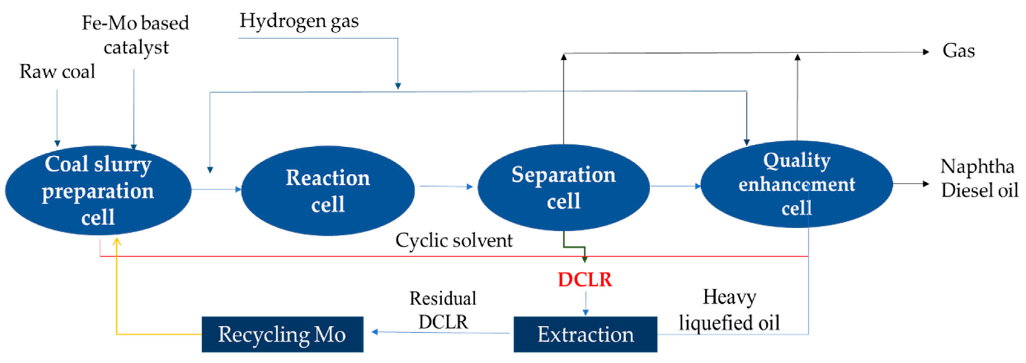
1. Introduction
2. Results and Discussion
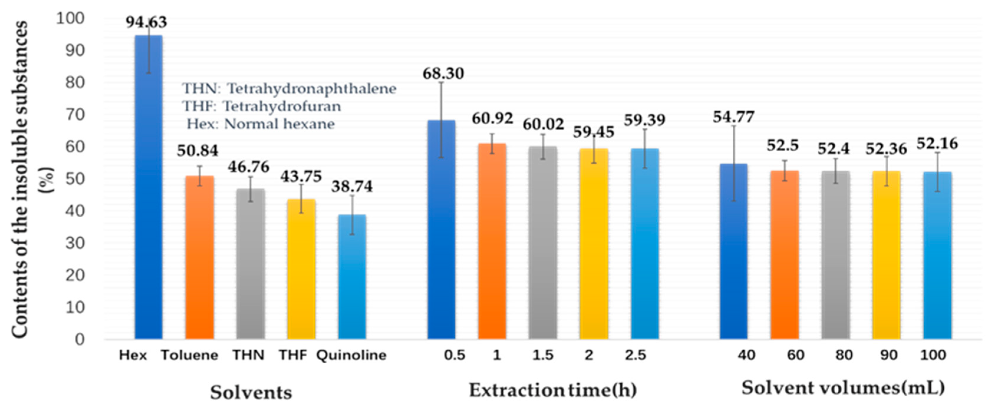
2.1. Solubility of the Original DCLR
2.2. Recycling Efficiency of Mo-Based Catalysts
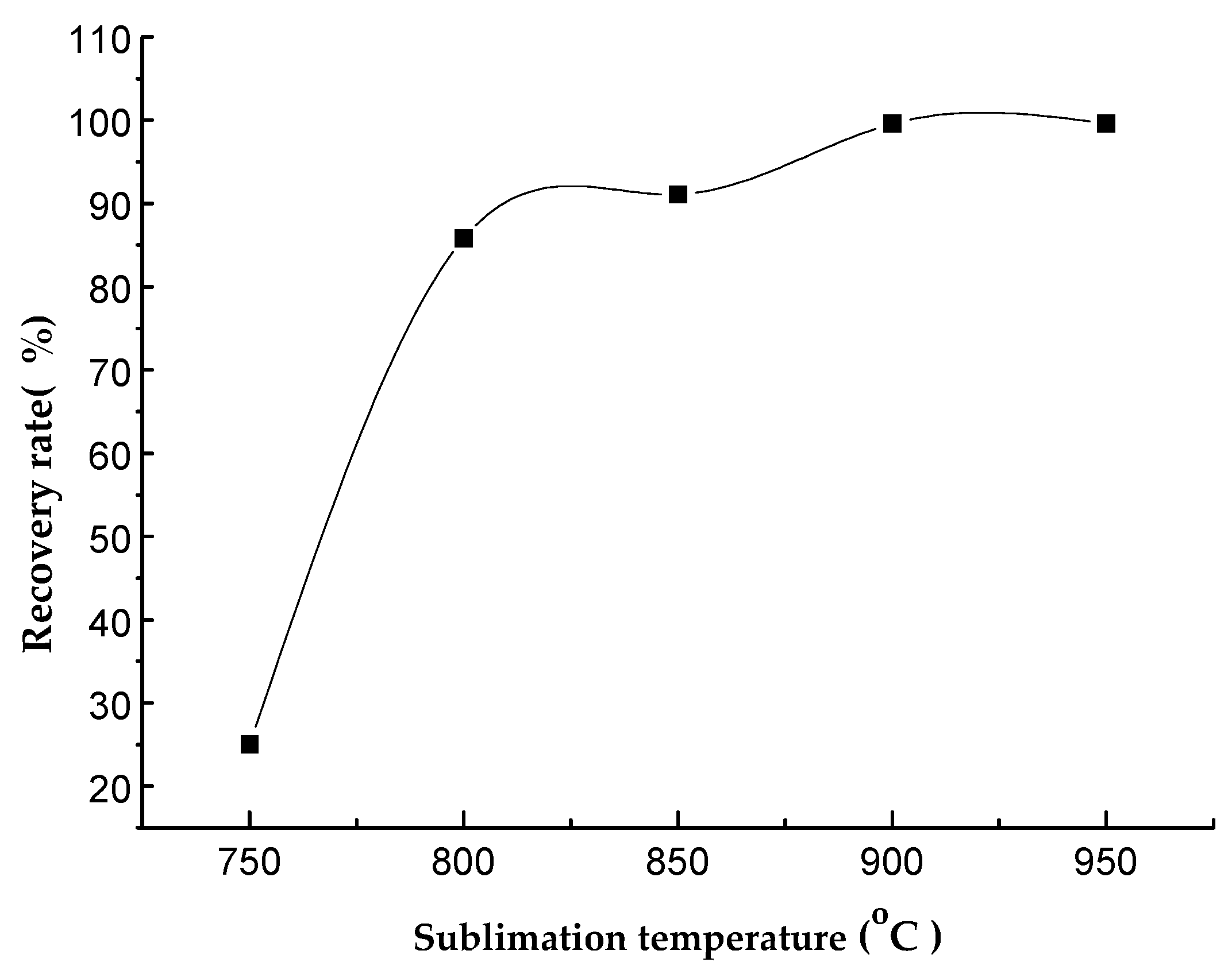
2.2.1. Sublimation Temperature
2.2.2. Sublimation Duration
2.2.3. Mo Concentration in the Residue DCLR after Extraction
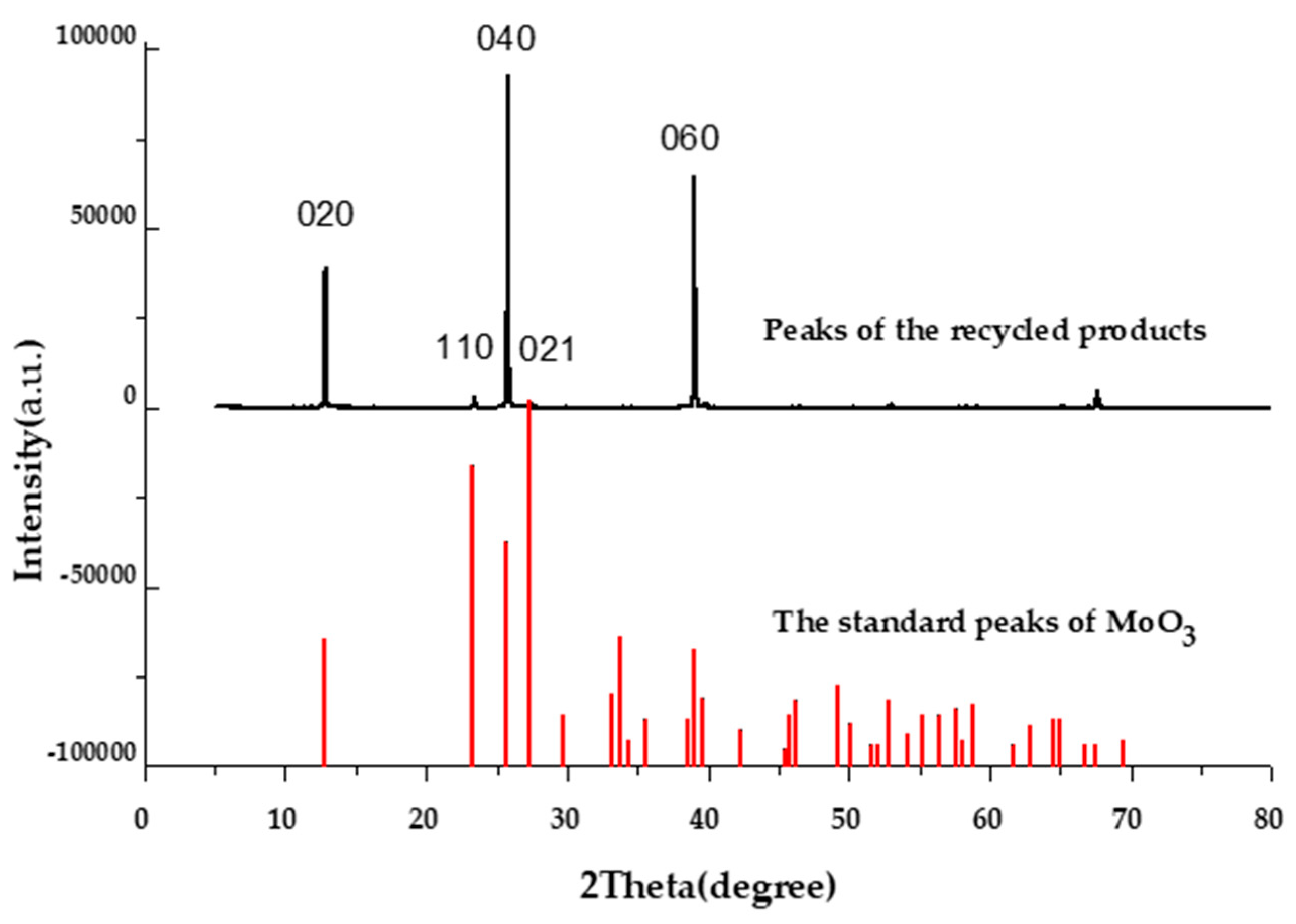
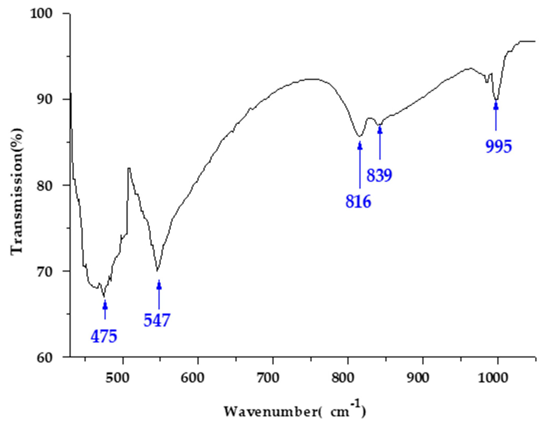
2.3. Characterization of the Recycled Mo-Based Products
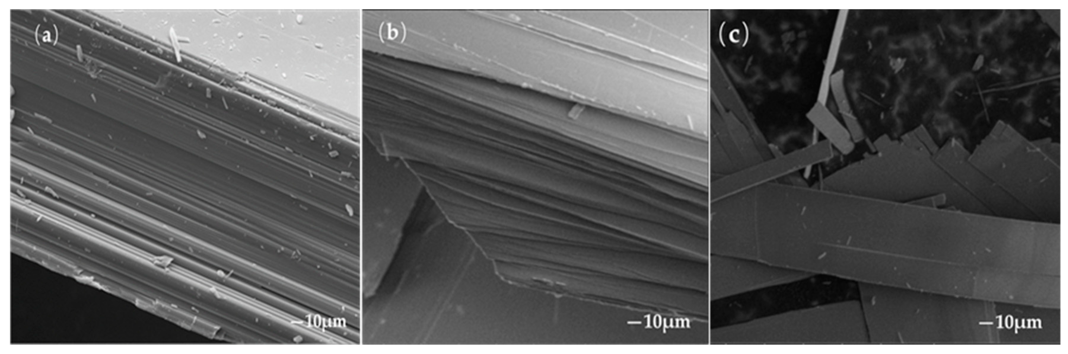
2.3.1. Microstructure Analysis
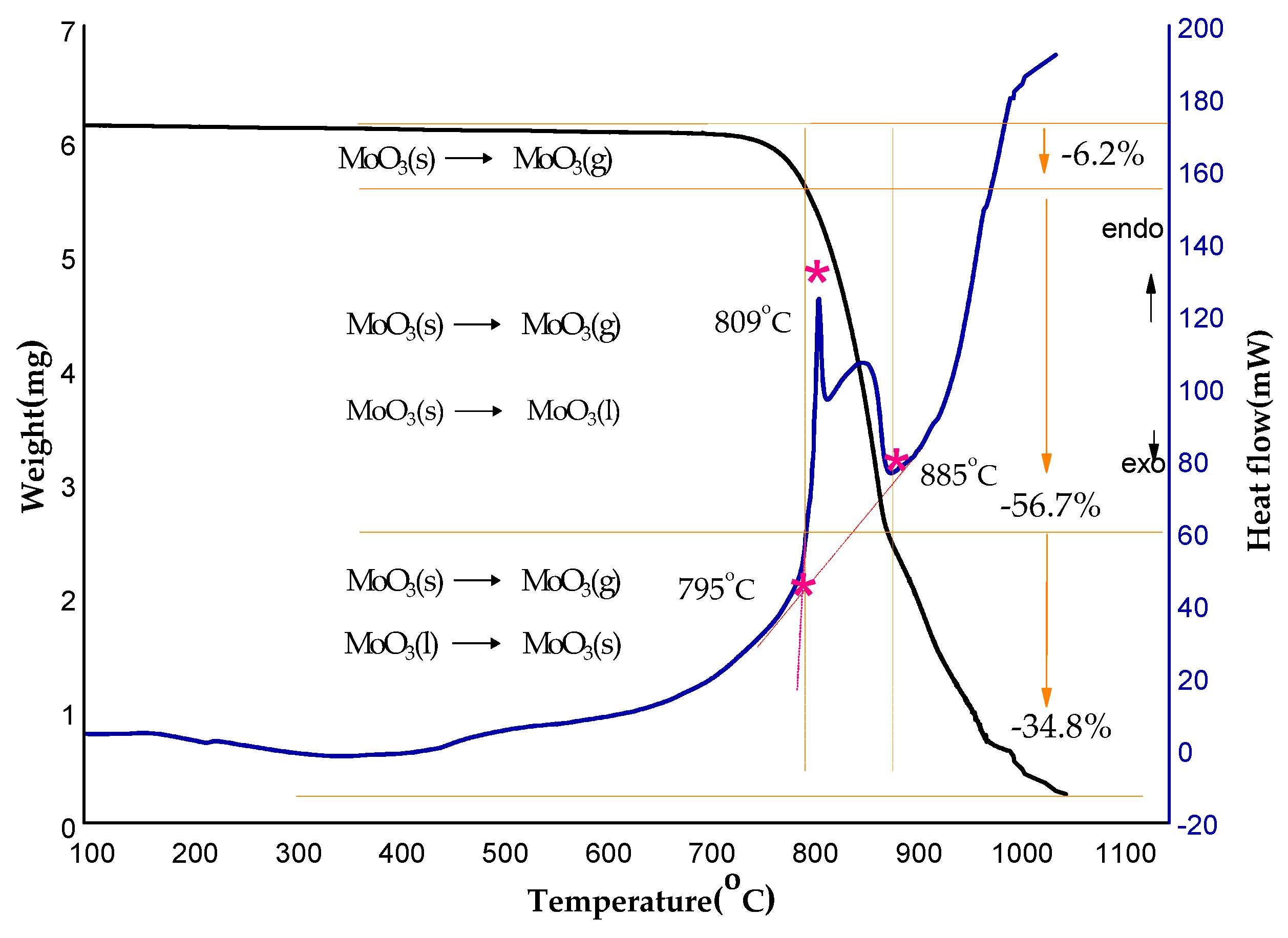
2.3.2. Thermal Stability of the Recycled Products
3. Materials and Methods
3.1. Reagents and Materials
3.2. Preparation of the Original DCLR
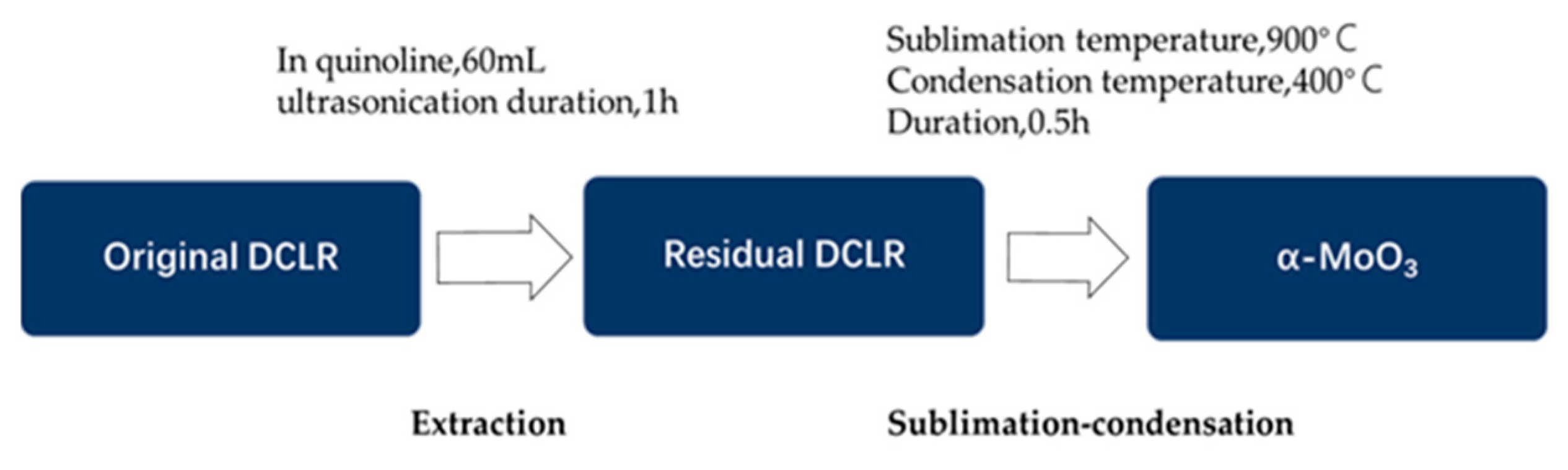
3.3. Extraction of the Original DCLR in Organic Solvents
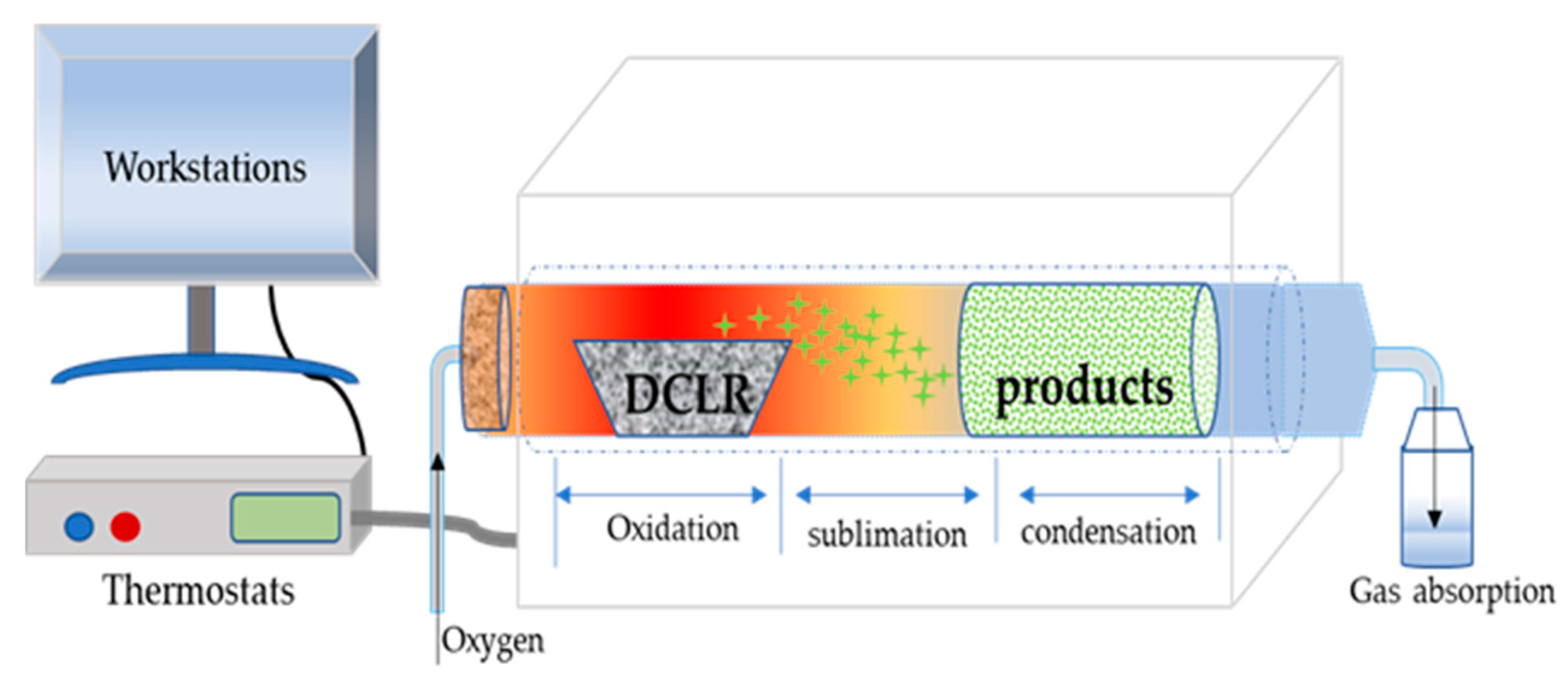
3.4. Recycling Mo from the Post-Extraction Residual DCLR
3.5. Microstructural Observation
4. Conclusions
Author Contributions
Funding
Acknowledgments
Conflicts of Interest
References
- Xie, K.C.; Wu, C.L. Direct coal liquefaction. In Chemical Industry, 1st ed.; Chemical Industry Press: Beijing, China, 2010; pp. 292–324. [Google Scholar]
- Shu, G.P.; Shi, S.D.; Li, K.J. Coal Liquefaction Technology, 1st ed.; China Coal Industry Publishing House: Beijing, China, 2003; pp. 23–30. [Google Scholar]
- Vasireddy, S.; Morreale, B.; Cugini, A.; Song, C.; Spivey, J.J. Clean liquid fuels from direct coal liquefaction: Chemistry, catalysis, technological status and challenges. Energy Environ. Sci. 2011, 4, 311–345. [Google Scholar] [CrossRef]
- Sheng, J.; Baikenov, M.I.; Liang, X.; Rao, X.; Ma, F.; Su, X.; Zhang, Y. Rapid separation and large-scale synthesis of β-FeOOH nanospindles for direct coal liquefaction. Fuel Process. Technol. 2017, 165, 80–86. [Google Scholar] [CrossRef]
- Ma, Z.B.; Shi, S.D. Study on direct coal liquefaction technologies. Coal Convers. 1992, 15, 68–78. [Google Scholar]
- Wu, X.Z.; Shu, G.P.; Li, K.J.; Xie, S.M. Technology and Engineering of Direct Coal Liquefaction Process, 1st ed.; Science Publishing House: Beijing, China, 2015; pp. 68–72. [Google Scholar]
- Li, W.B.; Li, K.J.; Shi, S.D.; Shu, G.P. The catalyst for direct coal liquefaction has achieved a breakthrough. China Sci. Technol. Achiev. 2006, 23, 34–35. [Google Scholar]
- Zhao, C.L.; Zhang, L.C.; Cao, S.K.; Jiang, R.Q. Applications of metals and metal sulphides in catalytic hydrocracking of coal and their related model compounds. Int. J. Oil Gas Coal Technol. 2016, 12, 142–161. [Google Scholar] [CrossRef]
- Raw Material Prices for Catalyst. Available online: www.worldmr.net (accessed on 22 February 2020).
- Li, P.; Zong, Z.M.; Wei, X.Y.; Wang, Y.G.; Fan, G.X. Structural features of liquefaction residue from Shenmu-Fugu subbituminous coal. Fuel 2019, 242, 819–827. [Google Scholar] [CrossRef]
- Hirano, K. Outline of NEDOL coal liquefaction process development (pilot plant program). Fuel Proc. Technol. 2000, 62, 109–118. [Google Scholar] [CrossRef]
- Khare, S.; Dell’Amico, M. An overview of conversion of residues from coal liquefaction processes. Can. J. Chem. Eng. 2013, 91, 324–331. [Google Scholar] [CrossRef]
- Yang, J.; Wang, Z.; Liu, Z.; Zhang, Y. Novel use of residue from direct coal liquefaction process. Energy Fuels 2009, 23, 4717–4722. [Google Scholar] [CrossRef]
- Xu, L.; Tang, M.; Liu, B.; Ma, X.; Zhang, Y.; Argyle, M.D.; Fan, M. Pyrolysis characteristics and kinetics of residue from China Shenhua industrial direct coal liquefaction plant. Thermochim. Acta 2014, 589, 1–10. [Google Scholar] [CrossRef]
- Chen, H.B.; Li, W.H. Microscopic characteristics and classification of Shendong coal hydroliquefaction residues. J. Fuel Chem. Technol. 2006, 34, 513–518. [Google Scholar]
- Xie, J.; Lu, H.F.; Chen, Y.F.; Shu, G.P.; Li, K.J.; Zhang, X.W.; Yang, G.L.; Wang, H.X. A Method for Recovery of Molybdenum from Coal Liquefaction Extraction Residues: China. Chinese Patent CN106521161A, 22 March 2017. [Google Scholar]
- Sebenik, R.F.; Hallada, C.J.; Barry, H.F.; Tsigdinos, G.A. Recovery and recycle of molybdenum values from coal liquefaction residue. Conserv. Recycl. 1983, 6, 80. [Google Scholar]
- Ference, R.A.; Sebenik, R.F. Molybdenum recovery from two types of direct catalytic coal liquefaction processes. In National Meeting of the American Chemical Society; Academic Press: Kansas City, MO, USA, 1982; Volume 27, pp. 71–77. [Google Scholar]
- Song, R.Y. Recovery of vanadium, molybdenum and uranium from high calcium coal ash. Compr. Util. Miner. Resour. 1981, Z1, 1–8. [Google Scholar]
- Kar, B. Carbothermic reduction of hydro-refining spent catalyst to extract molybdenum. Int. J. Miner. Process. 2005, 75, 249–253. [Google Scholar] [CrossRef]
- Gabala, L.; Dona, M. Valuable metals recovery from spent catalysts by selective chlorination. Resour. Conserv. Recycl. 1994, 10, 87–96. [Google Scholar] [CrossRef]
- Lai, Y.C.; Lee, W.J.; Huang, K.L.; Wu, C.M. Metal recovery from spent hydrodesulfurization catalysts using a combined acid-leaching and electrolysis process. J. Hazard. Mater. 2008, 154, 588–594. [Google Scholar] [CrossRef]
- Liu, D.; Lei, W.; Hao, J.; Liu, D.; Liu, B.; Wang, X.; Chen, X.; Cui, Q.; Zou, G.; Liu, J. High-pressure Raman scattering and X-ray diffraction of phase transition in MoO3. J. Appl. Phys. 2009, 105, 023513. [Google Scholar] [CrossRef]
- Zhu, B.; Li, C.; Cao, K.; Liang, J.; Tang, H. hydrothermal synthesis of MoO3 micro-belts. Int. J. Mater. Res. 2013, 104, 71–75. [Google Scholar] [CrossRef]
- Fang, L.; Shu, Y.; Wang, A.; Zhang, T. Green Synthesis and characterization of anisotropic uniform single-Cristal a-MoO3 nanostructures. J. Phys. Chem. C 2007, 111, 2401–2408. [Google Scholar] [CrossRef]
- Song, J.; Ni, X.; Gao, L.; Zheng, H. Synthesis of metastable h-MoO3 by simple chemical precipitation. Mater. Chem. Phys. 2007, 102, 245–248. [Google Scholar] [CrossRef]
- Gui, L.; Ma, C.B.; Yuan, Y.B. Structural feature and application of β-type molybdenum trioxide. Rare Met. Cem. Carbides 2004, 2, 35–38. [Google Scholar]
- Seguin, L.; Figlarz, M.; Cavagnat, R.; Lassègues, J.C. Infrared and Raman spectra of MoO3 molybdenum trioxides and MoO3 · xH2O molybdenum trioxide hydrates. Spectrochim. Acta A 1995, 51, 1323. [Google Scholar] [CrossRef]
- Rahman, M.; Adesanwo, T.; Gupta, R.; Klerk, A.D. Effect of direct coal liquefaction conditions on coal liquid quality. Energy Fuels 2015, 29, 3649–3657. [Google Scholar] [CrossRef]
- Fratczak, J.; Herrador, J.M.H.; Lederer, J.; Stevens, L.; Uguna, C.; Snape, C.; Pinto, F. Direct primary brown coal liquefaction via non-catalytic and catalytic co-processing with model, waste and petroleum-derived hydrogen donors. Fuel 2018, 234, 364–370. [Google Scholar] [CrossRef]
- Zheng, Q.X.; Zhang, Y.L.; Wahyudiono Fouquet, T.; Zeng, X.; Kanda, H.; Goto, M. Room-temperature extraction of direct coal liquefaction residue by liquefied dimethyl ether. Fuel 2020, 262, 116528. [Google Scholar] [CrossRef]


| MoO3 | Fe2O3 | Al2O3 | CaO | SiO2 | SO3 | ||
|---|---|---|---|---|---|---|---|
| Measuring conditions | Line | kα | Lα | kα | kα | kα | kα |
| Crystal | LiF200 | LiF200 | LiF200 | LiF200 | PE002 | LiF200 | |
| Content of each component (%) | Original DCLR | 49.93 | 0.17 | 3.63 | 0.03 | 0.06 | 44.79 |
| Residues after recycling | 65.60 | 10.70 | 2.68 | 8.19 | 7.25 | 0.00 |
| Sublimation Temperature (°C) | Condensation Temperature (°C) | Sublimation Duration (min) | Recycling Efficiency (%) |
|---|---|---|---|
| 900 | 400 | 60 | 99.6 |
| 900 | 400 | 45 | 99.6 |
| 900 | 400 | 30 | 99.6 |
| 900 | 400 | 15 | 78.1 |
| Contents of Mo in the DCLR Materials after Reaction (%) | Recycling Efficiency (%) |
|---|---|
| 40 | 40.5 |
| 50 | 78.5 |
| 55 | 87.6 |
| 60 | 99.5 |
| Samples | a/10−1 nm | b/10−1 nm | c/10−1 nm |
|---|---|---|---|
| 1 | 3.957 | 13.841 | 3.693 |
| 2 | 3.960 | 13.848 | 3.694 |
| α-MoO3 | 3.962 | 13.858 | 3.697 |
| Industrial Analysis (%) | Elemental Analysis (%) | Petrographic Analysis (%) | ||||||||||
|---|---|---|---|---|---|---|---|---|---|---|---|---|
| Mad | Ad | Vdaf | FCd | Cd | Hd | Nd | Sd | Od | Vitrinite | Inertinite | Exinite | Minerals |
| 4.72 | 7.62 | 37.73 | 57.53 | 74.15 | 4.97 | 0.99 | 0.26 | 12.01 | 54.6 | 41.7 | 1.2 | 2.5 |
© 2020 by the authors. Licensee MDPI, Basel, Switzerland. This article is an open access article distributed under the terms and conditions of the Creative Commons Attribution (CC BY) license (http://creativecommons.org/licenses/by/4.0/).
Share and Cite
Wu, C.; Luo, Y.; Zhao, K.; Yu, X.; Zhang, X.; Guo, X. Recycling Molybdenum from Direct Coal Liquefaction Residue: A New Approach to Enhance Recycling Efficiency. Catalysts 2020, 10, 306. https://doi.org/10.3390/catal10030306
Wu C, Luo Y, Zhao K, Yu X, Zhang X, Guo X. Recycling Molybdenum from Direct Coal Liquefaction Residue: A New Approach to Enhance Recycling Efficiency. Catalysts. 2020; 10(3):306. https://doi.org/10.3390/catal10030306
Chicago/Turabian StyleWu, Chunling, Yang Luo, Kai Zhao, Xiaobing Yu, Xian Zhang, and Xuqiang Guo. 2020. "Recycling Molybdenum from Direct Coal Liquefaction Residue: A New Approach to Enhance Recycling Efficiency" Catalysts 10, no. 3: 306. https://doi.org/10.3390/catal10030306
APA StyleWu, C., Luo, Y., Zhao, K., Yu, X., Zhang, X., & Guo, X. (2020). Recycling Molybdenum from Direct Coal Liquefaction Residue: A New Approach to Enhance Recycling Efficiency. Catalysts, 10(3), 306. https://doi.org/10.3390/catal10030306