Article

Plasma Generating—Chemical Looping Catalyst Synthesis by Microwave Plasma Shock for Nitrogen Fixation from Air and Hydrogen Production from Water for Agriculture and Energy Technologies in Global Warming Prevention

1
Department of Chemical and Biomolecular Engineering, Case Western Reserve University, Cleveland, OH 44106-7217, USA
2
Blacksea Advanced Technology Research and Application Centre (KITAM), Ondokuz Mayis University, 55139 Samsun, Turkey
3
School of Engineering, Newcastle University, Newcastle upon Tyne NE1 7RU, UK
Catalysts 2020, 10(2), 152; https://doi.org/10.3390/catal10020152
Submission received: 24 September 2019 / Revised: 20 December 2019 / Accepted: 15 January 2020 / Published: 27 January 2020

Abstract

:
Simultaneous generation of plasma by microwave irradiation of perovskite or the spinel type of silica supported porous catalyst oxides and their reduction by nitrogen in the presence of oxygen is demonstrated. As a result of plasma generation in air, NOx generation is accompanied by the development of highly heterogeneous regions in terms of chemical and morphological variations within the catalyst. Regions of almost completely reduced catalyst are dispersed within the catalyst oxide, across micron-scale domains. The quantification of the catalyst heterogeneity and evaluation of catalyst structure are studied using Scanning Electron Microscopy, Energy Dispersive X-ray Spectroscopy and XRD. Plasma generating supported spinel catalysts are synthesized using the technique developed by the author (Catalysts; 2016; 6; 80) and BaTiO3 is used to exemplify perovskites. Silica supported catalyst systems are represented as M/Si = X (single catalysts) or as M(1)/M(2)/Si = X/Y/Z (binary catalysts) where M; M(1) M(2) = Cr; Mn; Fe; Co; Cu and X, Y, Z are the molar ratio of the catalysts and SiO2 support. Composite porous catalysts are synthesized using a mixture of Co and BaTiO3. In all the catalysts, structural heterogeneity manifests itself through defects, phase separation and increased porosity resulting in the creation of the high activity sites. The chemical heterogeneity results in reduced and oxidized domains and in very large changes in catalyst/support ratio. High electrical potential activity within BaTiO3 particles is observed through the formation of electrical treeing. Plasma generation starts as soon as the supported catalyst is synthesized. Two conditions for plasma generation are observed: Metal/Silica molar ratio should be > 1/2 and the resulting oxide should be spinel type; represented as MaOb (a = 3; b = 4 for single catalyst). Composite catalysts are represented as {M/Si = X}/BaTiO3 and obtained from the catalyst/silica precursor fluid with BaTiO3 particles which undergo fragmentation during microwave irradiation. Further irradiation causes plasma generation, NOx formation and lattice oxygen depletion. Partially reduced spinels are represented as MaOb–c. These reactions occur through a chemical looping process in micron-scale domains on the porous catalyst surface. Therefore; it is possible to scale-up this process to obtain NOx from MaOb for nitric acid production and H2 generation from MaOb–c by catalyst re-oxidized by water. Re-oxidation by CO2 delivers CO as fuel. These findings explain the mechanism of conversion of combustion gases (CO2 + N2) to CO and NOx via a chemical looping process. Mechanism of catalyst generation is proposed and the resulting structural inhomogeneity is characterized. Plasma generating catalysts also represent a new form of Radar Absorbing Material (RAM) for stealth and protection from radiation in which electromagnetic energy is dissipated by plasma generation and catalytic reactions. These catalytic RAMs can be expected to be more efficient in frequency independent microwave absorption.

1. Introduction

The objective of this paper is to provide the background study of novel silica supported catalysts, which generate plasma under microwave irradiation resulting in nitric oxide and nitrogen dioxide (NOx) production from air. These catalysts have either spinel- or perovskite-structures. In this process, spinel- or perovskite-type catalysts are reduced by nitrogen (even in the presence of oxygen when air is used) through lattice oxygen abstraction and NOx generation. This reduction process takes place simultaneously with plasma generation when the catalyst is subjected to microwave radiation. In this process, reactive separation of air occurs in which N2 can then be used in ammonia (NH3) synthesis. In the next stage, spinel- or perovskite-catalysts are re-oxidized (catalyst regeneration) with water as oxidant to produce H2 for use in ammonia production. Therefore, through a chemical looping process, it is possible to obtain both nitric acid (HNO3) and NH3 as well as NH4NO3 fertilizers from air and water using electricity as a processing energy. Spinel- or perovskite-catalyst regeneration can also be carried out using combustion gases (CO2 + N2) when CO2 is converted to CO. The present study is an extension of recent studies by the author [1,2,3] on catalyst, plasma reactor/process design, and NH3/fertilizer synthesis. Below, a brief review of the relevant studies is given.

1.1. Thermochemical Redox Cycle for the Production of Hydrogen from Water and Carbon Monoxide from Carbon Dioxide

The best-known example of the spinel-type of catalyst used for H2 generation from water and CO generation from CO2, is ferrite spinel, with following redox reactions:
Fe3O4 → 3FeO + ½ O2 (Reduction)
3FeO + H2O → Fe3O4 + H2 (Oxidation–H2 generation from H2O)
3FeO + CO2 → Fe3O4 + CO (Oxidation–CO generation from CO2)
The above two-stage thermochemical cycle was first proposed by Nakamura [4] although the reduction stage is not viable for unsupported iron oxide, as it requires temperatures in excess of the melting point of the metal. Supported iron oxide overcomes this problem [5]. Thermal reduction temperature is lowered by using mixed oxides [6], such as MxFe3−xO4 where M = Mn, Co, Ni, Zn. Currently, thermochemical redox cycles operate at 1300 °C obtained using concentrated solar-thermal energy [7,8,9]. Localized temperatures well above 1000 °C can also be obtained by nonthermal plasma without affecting the catalyst, and energy efficiency can be enhanced by the imposition of pulsed power.

1.2. Nitrogen Fixation

Nitrogen fixation from air and hydrogen generation from water are two ideal processes for sustainable food and energy production. Coupled with an efficient preservation and utilization of water which will prevent the Food, Energy and Water shortages that are deemed to emerge as a result of global warming and population increase. Agriculture consumes 85% of global water and NH3 supply [1,3]. Ammonia itself consumes 87% of the industrial energy, which accounts for ca. 3% of global energy consumption. In the displacement of fossil fuels by renewables, green ammonia can play a major role as direct transport fuel and hydrogen storage thus increasing ammonia’s share of the global energy value to 30%.
In the production of NH3 and nitric oxide (NO), plasma is seen as a very efficient technique of nitrogen activation. Several recent publications/reviews are available on the subject [10,11,12,13,14,15,16,17,18,19,20,21,22,23,24,25,26,27,28,29,30,31]. The efficiency of N2-fixation via NH3 or NO production is primarily dictated by N2-activation, water splitting and their selectivity which can be maximized through the design of catalyst, reactor and process. Any new commercial NH3 process should achieve the energy efficiency of the current Haber-Bosch process which, after a century of development has now reached its theoretical cost of 0.48 MJ/mol of NH3. Ammonia production using nonthermal plasma has a theoretical cost of 0.20 MJ/mol thus making nonthermal plasma activation an attractive route for NH3 synthesis [2,17,18,19,20,21,22,23,24,25,26,27,28,29,30,31]. However, a number of techno-economical barriers should be overcome before plasma-based nitrogen fixation can deliver an alternative to the Haber-Bosch process for NH3. These conditions include:
(a)
Ammonia yield should be ca. 15–20% as currently practiced in Haber Bosch processes [2,12,13,18,24,25,26,27]. Currently, this condition is achieved [2,3,14,16], especially if NH3 is sequestrated by acids to obtain ammonium salt-based fertilizers [2,3].
(b)
The energy cost (Specific Energy Input, SEI) of NH3 should match that of the Haber-Bosch (at SEI = 0.5 MJ/mol). Literature on plasma based NH3 synthesis indicates that SEI decreases rapidly with the gas flow rate resulting in low SEI without significant yield [23,24,25,26,27,28,29,30]. Furthermore, the catalyst, as well as the plasma source also effect the yield and energy efficiencies. For example, Kim et al. [17] obtained a very high energy efficiency of 30 g NH3/kWh at an ammonia yield of 0.8% using Ru catalyst, whereas Shah et. al. [25] obtained 0.19 g NH3/kWh at 19.1% yielded with a gold catalyst. The catalyst and plasma reactor systems described by Akay [2] obtained ca. 19.4% yield at 4.6 g NH3/kWh (without optimization) using nickel catalysts with BaTiO3 particles, while the final product was an advanced fertilizer which also acts as a synthetic root system for plant growth and yield enhancement, especially under water and nutrient stress [2,32,33,34].
(c)
In all of these studies, raw materials, capital, and operating costs are not included in the true cost of NH3. It is likely that through the application of process intensification principles in plasma based catalytic NH3 synthesis, the capital and operating costs can be expected to be smaller compared with Haber-Bosch plants, even though the production capacity of the new plants can be several orders of magnitude smaller [35]. Capital cost of the processes based on intensification have very weak dependence on plant capacity. However, the cost of H2 from renewable sources is still high. Sustainable NH3 production needs to address the high cost of hydrogen [12,19,29].
(d)
As 85% NH3 is used in fertilizer production, direct fertilizer production should be considered as a means of enhancing NH3 yield as demonstrated recently [2,3]. Ammonium nitrate is the most efficient and widely used fertilizer due to its very high nitrogen content and ease of plant uptake [32,36,37]. Some 80% of HNO3 is consumed in ammonium nitrate production. Presently, HNO3 is produced from NH3 oxidation [38,39]. Methane is the preferred feedstock for the Haber-Bosch NH3 thus the current HNO3 production is even more energy intensive compared with NH3. Alternative routes based on plasma via nitric oxide production have been the subject of considerable research [10,11,12,13,14,15,24] with several reviews of recent progress [12,13,19,20,21,22,28,29]. Although the NH3 route provides both nitrogen, hydrogen and energy for nitric acid production, plasma nitrogen fixation only provides nitrogen, hence H2 needs to be provided from another source for both NH3 and HNO3. It is possible to electrochemically oxidize N2 to HNO3 as a means of direct N2 and H2 fixation from air and water as proposed recently [28]. The method provided in this current study, essentially achieves the same result proposed by Chen et al. [28] through microwave induced catalytic plasma with chemical looping in HNO3 production.

1.3. Chemical Looping with Plasma Catalysts

Chemical looping is best known in combustion [40,41,42] when oxygen for combustion is provided by the lattice oxygen of a metal oxide. In a separate reactor, lattice oxygen is restored via oxidation when it is possible to obtain hydrogen using water. The application of thermochemical looping to production NH3 using metal nitride catalysts [43] or plasma induced chemical looping [44] have been considered. Nitric oxide from NH3 using metal oxides in thermochemical looping are also available [45,46].

1.4. Catalysts for Nitrogen Fixation from Air and Hydrogen Generation from Water

Plasma N2-fixation can take place without a catalyst which nevertheless enhances yield and energy efficiency especially at a high energy input [12,47]. In order to achieve a high surface area and the accessibility of catalytic sites, catalysts are supported using alumina, silica, titania, ceria, zeolites. More recently, catalyst supports included graphene [48], nano-sheets/plates obtained through the exfoliation of cation-exchangeable layered transition metal oxides [49,50] and carbon nanofibers and nanotubes [51,52]. Some supports are inert and their effectiveness (selectivity, yield and energy efficiency) are attributed to surface area enhancement [53], while others can form new phases with the catalysts [54,55]. Other supports, such as ceria, also act as a catalyst and in the presence of a co-catalyst to promote activity [56]. Reviews of recent progress in new catalytic materials are available [57,58].
The catalysts used in this study are perovskites with general formula of ABO3 [59,60,61,62] or spinel oxides with a general formula of AB2O4 which are often used in heterogeneous catalysis due to their well-defined, controllable structure and tunable redox properties [62,63,64]. Here, A and B are two suitable metals.
Unlike electrocatalysts, plasma catalysts should have low conductivity to prevent local electrical discharges, especially at high metal catalyst loadings [16]. The co-assembled silica supported catalyst system [1] is produced when flow and energy source (such as thermal, microwave, ultra-violet or ultra-sound) are superimposed so as to form thin films of the catalyst and support precursor fluids. The resulting catalyst has a lamellar structure with repeated support and catalyst layers. As a result, they have low conductivity. In these mixed oxides or silica-metal complexes, the silica support is ~1 nm thick with XRD-evaluated catalyst size typically 2–10 nm. Although not fully evaluated, the catalyst structure is similar to graphene or exfoliated nano-plate supported catalysts, except that the structure formation takes place through the co-assembly of the support and catalyst precursors during processing. The catalyst support structure is not preformed. The resulting agglomerates are highly porous with a bulk density less than 0.1–0.2 g/cm3 and BET surface area ~300–100 m2/g even at very high metal loadings [16]. Although silica is the primary support, carbon (which is present on silica support) can also be utilized as co-support for certain applications [1].
Most suitable metals for chemical looping through thermal steam oxidation of the reduced catalyst for hydrogen generation are Fe, Ni, Cu, Mn and Co [42,45,46]. The selection criteria are based on oxygen carrying capacity, melting point, minimum oxidation temperature and cost.

1.5. Plasma Generation, Plasma Reactors and Integrated Processes

A large number of studies are available for thermal and nonthermal plasma generation and reactor systems. [2,3,12,20,21,22,23,24,25,26,27,29,65,66]. The incorporation of the plasma field into a catalytic reactor has also been considered with emphasis on electrode configuration and scale-up [65,66,67,68]. In order to achieve high product yield, selectivity and energy efficiency, integration of the other unit operation with the plasma reactor should be considered [2,3]. Sustainability of the technology can be further improved if integration at a global scale is achieved [2,3,69,70].

2. Results

2.1. Critical Microwave Power P*

The critical power P* was evaluated when M/Si = 1/3 (i.e., 25 mol% catalyst) for several catalysts or co-catalysts. Because the microwave power could only be changed stepwise, these values are not accurate but clearly demonstrate the existence of a critical power. Here P* refers to the machine power input when it is possible to achieve catalyst nitrate salt decomposition below which decomposition does not take place unless the temperature is increased to ca. 600 °C to achieve thermal decomposition. These results are shown in Table 1 for selected d-block (transition) metal catalysts and Table 2 for selected s- and p-block metals (catalyst promoters) as a function of atomic number.
Table 1 shows that, for transition d-metal catalysts, the critical power increases with the atomic number, although the minimum microwave power was 340 W. It was also found that with the exception of Fe, the catalyst precursor fluids were stable even after 4 years of storage. There were no discernable differences in P* values, as well as with respect to the catalyst properties such as crystallite size and surface area, between the catalysts synthesized from the fresh and stored (four years) catalyst precursor fluids. As shown previously [1], in the case of Fe/Si, the catalyst precursor fluid gradually gels and NOx starts to evolve due to the decomposition of ferric nitrate, especially when the fluid is exposed to light.
We also present the tap density (which indicates porosity) of the freshly prepared porous expanded solid material obtained after microwave radiation following the evaporation of water and nitrate decomposition. These experiments were carried out at 900 W microwave power input because it was found that the tap density is also dependent on the microwave power. Note that in the case of Cu, at Cu/Si = 1/3, there is no nitrate decomposition but a porous structure is still obtained after water evaporation. It can be seen from Table 1, the tap density for the transition metal oxide catalysts is approximately constant at ca. 0.065 g/cm3.
Table 2 indicates that the critical power is relatively low for the catalyst promoters; P* = 450 W for Mg, Ca, Ba, Zn, Bi, La and P* is < 340 W for Sr and Al. Similarly, the tap density is approximately constant at 0.18 g/cc for Mg, Ca, Sr, Ba, Zn, Bi while for Al and La, the tap density is ca. 0.057 g/cc, similar to those of the transition metal catalyst oxides as shown in Table 1. The concentration dependence of P* is investigated for Mn, Co and Cu. The results are tabulated in Table 3.
Table 3 indicates that for Mn, P* is less than 340 W at all concentrations studied (16.7–66.7 mol%) whereas for Cu, P* increases with concentration from 1.26 kW at 16.7 mol% to P* > 1.8 kW when catalyst concentration is 25 mol% or above. However, it was found that when a binary catalyst system was used in which one of the metals has a very high critical power, such as Cu, the resulting catalyst precursor has a considerably lower critical power. For example, P* for Cu/Si = 1/3, is above 1800 W and for Co/Si = 1/3, P* = 720 W, while for Zn/Si = 1/3 P* = 900 W. For the binary catalysts, while keeping the total metal-silica ratio constant at 1/3 (i.e., MT/Si = 1/3) Co/Cu/Si = 1/1/6 and Co/Zn/Si = 1/1/6, P* < 340 W.
Most importantly, it can be seen from Table 3, that for cobalt, P* reaches maximum at 720 W when Co/Si = 1/3. Unlike Cu, further increase in Co concentration results in decrease in P*. This behavior is associated with plasma generation during microwave irradiation of certain types of catalyst oxides (spinels) when the total catalyst concentration (MT) and silica molar ratio, MT/Si, is above a critical level.

2.2. Plasma Generation during Microwave Irradiation

It was observed that when M/Si > 1/2 (M = Mn or Co), even at the critical power P*, the catalyst precursor (Mn(NO3)2 and Co(NO3)2) decomposition is accompanied by glowing (i.e., plasma generation) under microwave irradiation even before the completion of the NO2 evolution due to nitrate decomposition. We note that the critical power P* for Co increases with increasing Co concentration and P* reaches maximum at P* = 720 W when Co/Si = 1/3. When Co/Si = 1/2, P* = 540 W which is accompanied with the start of the plasma generation. Further increases in Co/Si values results in reduction in P* and plasma generation continues.
In order to investigate the effect of plasma generation on the catalyst structure, subsequent experiments were carried out using Mn and Co at microwave power P = 1800 W at various catalyst concentrations. Typically, at this power (P = 1800 W), the experiments take 60 s. Of this 60 s, 20 sec is used for water evaporation, 20 sec is consumed for nitrate decomposition, towards the end of which plasma starts. Plasma is allowed to continue for another 20 s. Temperature of the resulting catalyst was measured using an IR-thermometer immediately after the stopping of the microwave irradiation. Typical, final temperature was ca. 270–300 °C at P = 1800 W. However, the expected local temperatures within the catalyst can reach 2000 °C rapidly and therefore the catalyst preparation takes place under non-equilibrium conditions. In some experiments, the resulting catalyst was allowed to cool down to room temperature and subjected to further microwave irradiation. Once again, with Mn and Co catalysts, plasma was generated if M/Si > 1/2. In all cases, when the microwave power was turned off, the plasma itself was extinguished within seconds.

2.3. Microwave Induced Plasma Generation with Barium Titanate

Barium titanate (BT) was previously used as a plasma catalysis promoter [2,3,14,16,68] in nonthermal plasma reactors. When used with a catalyst in a mixture, BT provided a synergy [14,16] for the enhancement of NH3 yield. In this study, we use BT particles to co-generate silica supported Co catalysts represented as {M/Si = X}/BT = F, where F is the catalyst/BaTiO3 molar ratio. It is possible [3,14] to obtain either dispersed M/Si = X and BT particles or M/Si = X core with coated BT particles, or alternatively, large BT-spheres coated with the catalysts M/Si = X.
It was found that when BT-spheres (which were washed with HNO3 and water) were irradiated with microwave, they also produce plasma and prolonged irradiation and plasma generation caused structural changes as determined by Scanning Electron Microscopy (SEM) and X-Ray Diffraction (XRD) in which crystallite size was also determined [71]. It is therefore possible to obtain M/Si = X and BT-particles which can enhance a more energy efficient plasma generation by microwave. Figure 1 illustrates the generation of nitric oxide, NO, during microwave radiation of barium titanate particles in air. Here, we used a programmed microwave irradiation which provides a more energy efficient nitrogen fixation in air. If the full microwave power (at 200 W) is imposed during processing, after an induction period of ca. 30 s, nitric oxide generation reaches above 500 ppm (maximum detection limit) within 40 s.

2.4. Catalyst BET Surface Area

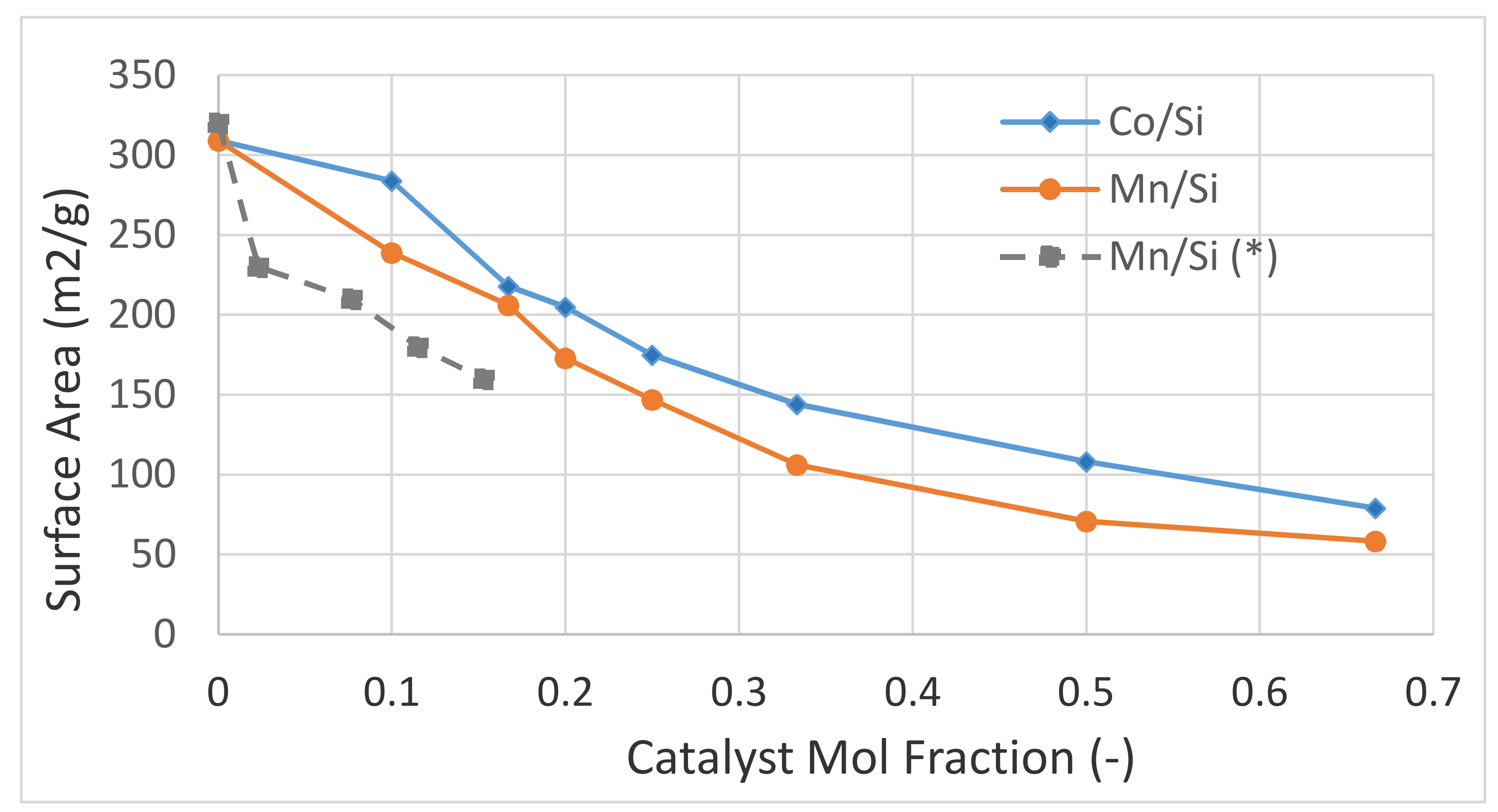
The variation of the BET surface area with catalyst mol fraction is shown in Figure 2 for Co/Si = X and Mn/Si = X prepared by microwave irradiation of the combined catalyst support (coated silica) and catalyst precursor fluid in air at a microwave power of 900 W. We also included data from Reed et al. [72] for Mn/Si (*) in which the supported catalyst was prepared by the traditional incipient method using uncoated silica particles as support.
It can be seen from Figure 2 that initially, the catalyst surface area decays rapidly with increasing catalyst loading. The surface area decay rate decreases with increasing catalyst concentration. Surface area of Co/Si is higher compared with Mn/Si despite the fact that the densities of Co and Co3O4 are significantly higher than that of Mn and Mn3O4. In these catalysts, the oxide spinels Co3O4 and Mn3O4 are the main components of the catalysts. It was shown previously [1] that when the BET surface areas are normalized with respect to density of the catalyst, at high catalyst concentrations (above ca. 25 mol%) the surface area is in fact higher than that of the support, SiO2, indicating that the size of the catalyst crystallites is smaller than that of the support at 7 nm. It can also be seen that the Mn/Si catalyst obtained by the incipient wet impregnation method using uncoated silica with similar silica size (5 nm) yields a smaller surface area because of the difference in the preparation methods as detailed previously [1].

2.5. X-Ray Diffraction (XRD) Studies

The catalyst samples were subjected to powder XRD measurements in order to identify composition, but primarily crystallite size. When the supported catalyst is prepared by using a solid support through the incipient wetness impregnation method, XRD-based crystallize size matches very well with that obtained by BET, TEM or HRSEM [73,74]. This is because for this type of supported catalysts, the support and catalyst domains are discrete. Furthermore, the XRD based catalyst crystallite size using Scherrer’s equation [71], and the crystallite size based on various reflections agree well [74].
XRD profiles of the catalyst oxides obtained from the microwave irradiation of the supported catalyst precursor fluid (Silane coated SiO2 dispersion in water containing the dissolved metal nitrate salt) results in M3O4 (M = Mn, Co) spinels. As both Mn and Co have multivalence, it is also possible to have CoO, Co2O3, MnO, Mn2O3 and MnO2. However, for our purpose of evaluating crystallite size, we use the dominant peak, which is associated with the spinel structure of M3O4 in determining the crystallite size.
The diffraction angles (2θ) and the associated reflection planes (shown in parenthesis after 2θ) for BaTiO3 [75], Co3O4 [1,76] and Mn3O4 [77] are shown below:
  • BaTiO3—2θ, (Reflection plane) = 22.2°, (100); 31.6°, (101); 39.0°, (111); 45.1°, (002); 45.5°, (200); 50.8°, (102); 51.1°, (201); 56.1°, (112); 56.4°, (211); 65.5°, (202); 66.2°, (220).
  • Co3O4—2θ, (Reflection plane) = 19.0°, (111); 31.3°, (220); 36.9°, (311); 44.8°, (400); 59.4°, (511); 65.2°, (440).
  • Mn3O4—2θ, (Reflection plane) = 17.8°, (101); 28.7°, (112); 32.2°, (103); 36.1°, (211); 37.8°, (004); 44.2°, (220); 50.4°, (105); 58.2°, (321); 59.6°, (224); 64.6°, (400); 73.8° (413).
Dominant phases appear at 2θ = 22° (very broad amorphous SiO2 diffraction angle); 31.4° (BaTiO3); 36.9° (Co3O4) and 33.0° (Mn3O4).

2.6. XRD Studies of Silica Support and Barium Titanate

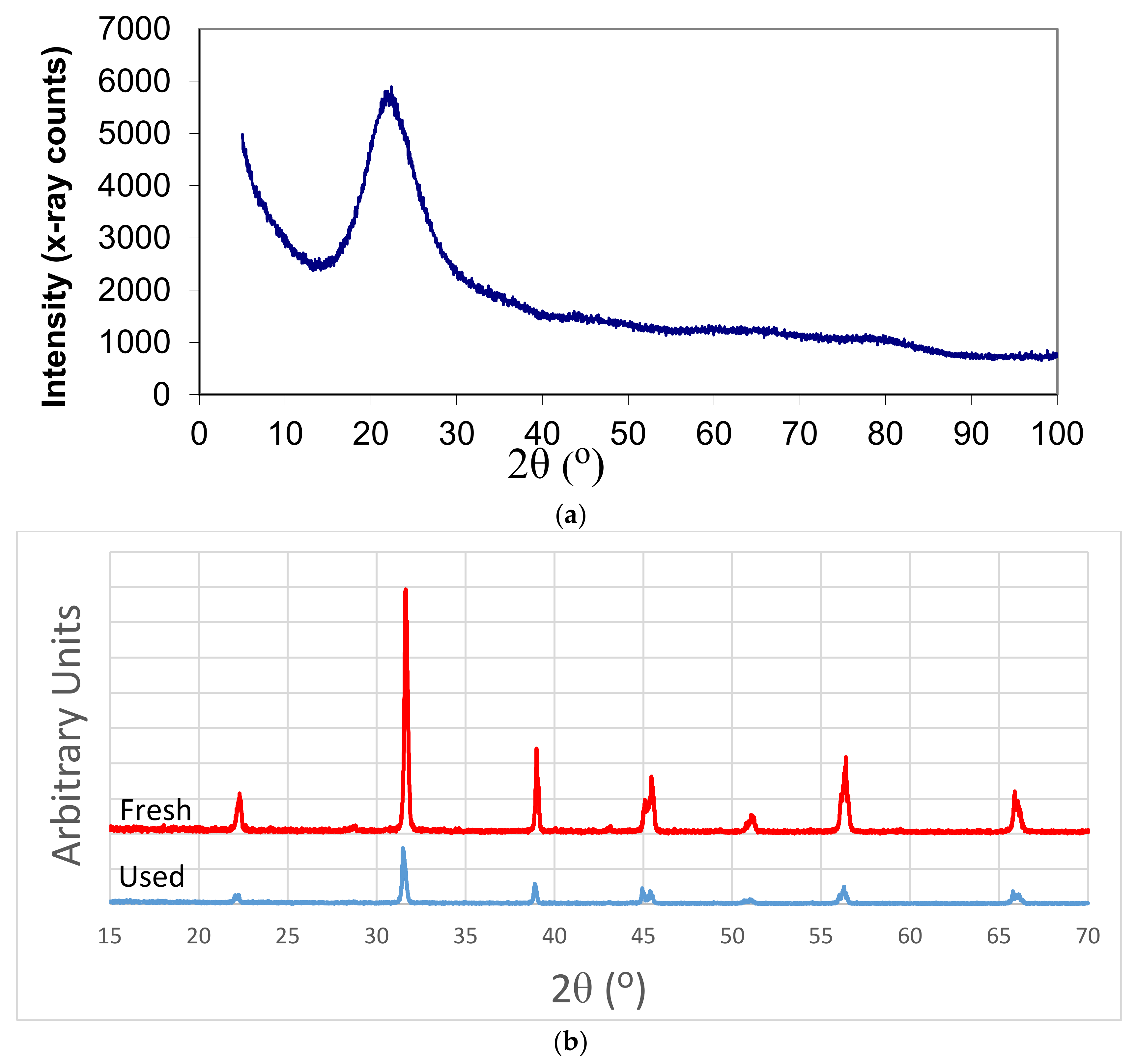
Silica powder was obtained by microwave irradiation of the support fluid (silane coated silica fluid containing 30 wt% silica) at 1800 W for 3 min in air. BaTiO3 spheres (3 mm diameter) were irradiated for 2 min at 1800 W and allowed to cool to room temperature. The process is repeated five times. Fresh and microwave irradiated BaTiO3 particles were then crushed and XRD measurements were taken. The results are shown in Figure 3a,b. It can be seen from Figure 3a that silica is amorphous with a broad peak around 2θ = 22°. Barium titanate before and after microwave irradiation does not show any significant variation in peak position or appearance of new phases as seen in Figure 3b. However, it is found that microwave radiation and plasma generation result in the reversal of the intensities associated with phases (002) and (200); (102) and (201); (112) and (211); (202) and (220). The XRD patterns in Figure 3b indicate that the crystallographic structure of both BaTiO3 samples is tetragonal at room temperature. The intensity reversal indicates that the polycrystalline ferroelectric BaTiO3 had acquired piezoelectric domains through dipole alignment [78]. This transformation is reflected when ferroelectric ceramics are poled to induce piezoelectric functionality through the application of a high electric field across the ceramic materials [78]. In ceramic poling, the application of the electric field is directional, whereas in the present case of microwave irradiation BaTiO3 spheres, the dipole orientation field is random which thus introduces localized piezoelectric domains.
The dominant phase (110) (appearing at 2θ = 31.6°) is a highly orientated phase and it can be promoted through processing [75]. However, due to sintering, crystallite size at 2θ = 31.6° increases upon irradiation from 43.6 nm to 79.9 nm. The increase in crystallite size across most of the reflections is observed as shown on Table 4. The intensities of the peaks at 2θ = 45.1° (Reflection (002)) and 2θ = 66.2° (Reflection (220)) increase upon irradiation. The peak at 2θ = 66.2° for the fresh sample is too weak to calculate the crystallite size.

2.7. XRD Studies of Silica Supported Co/Si = X and Mn/Si = X Catalysts

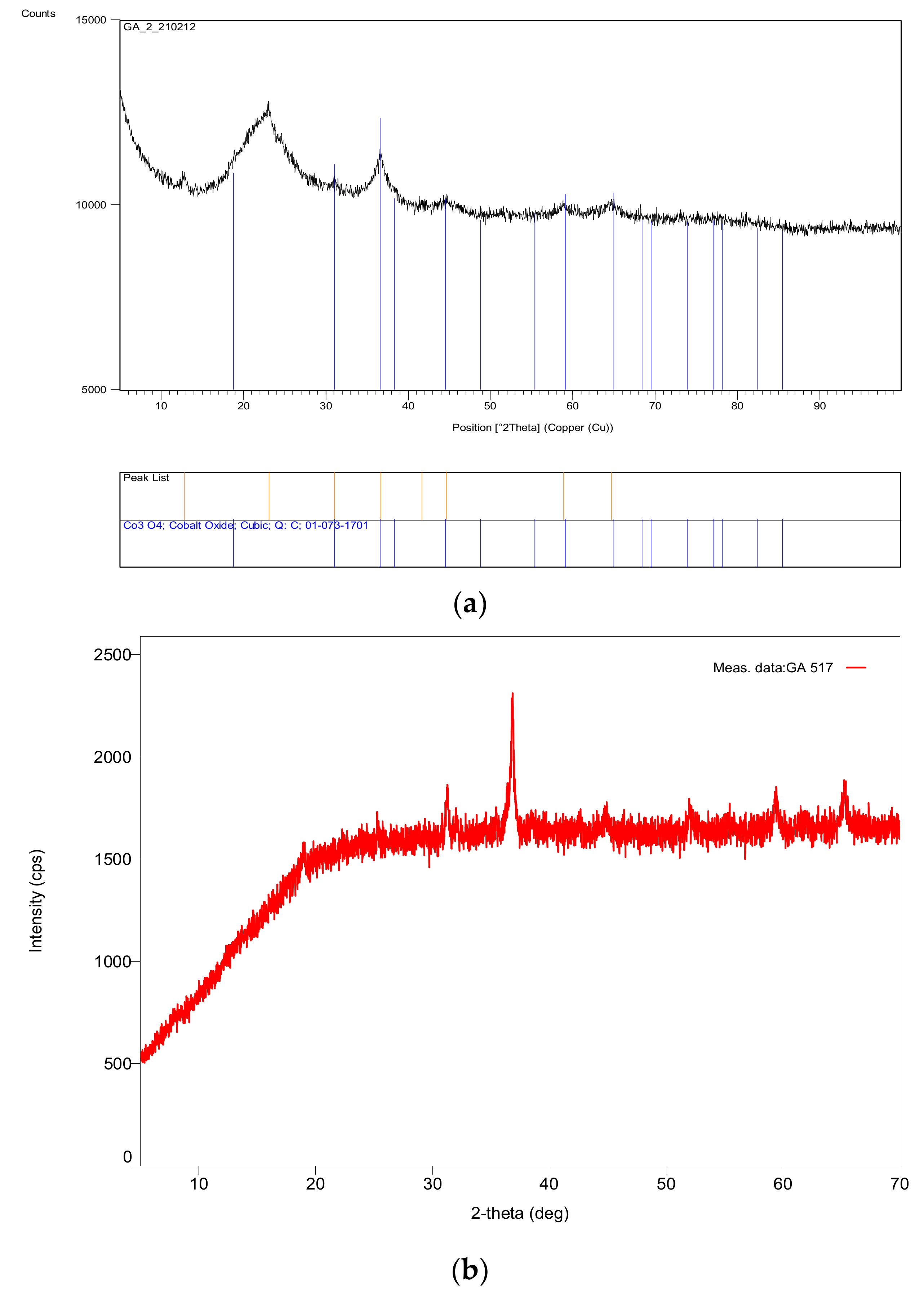
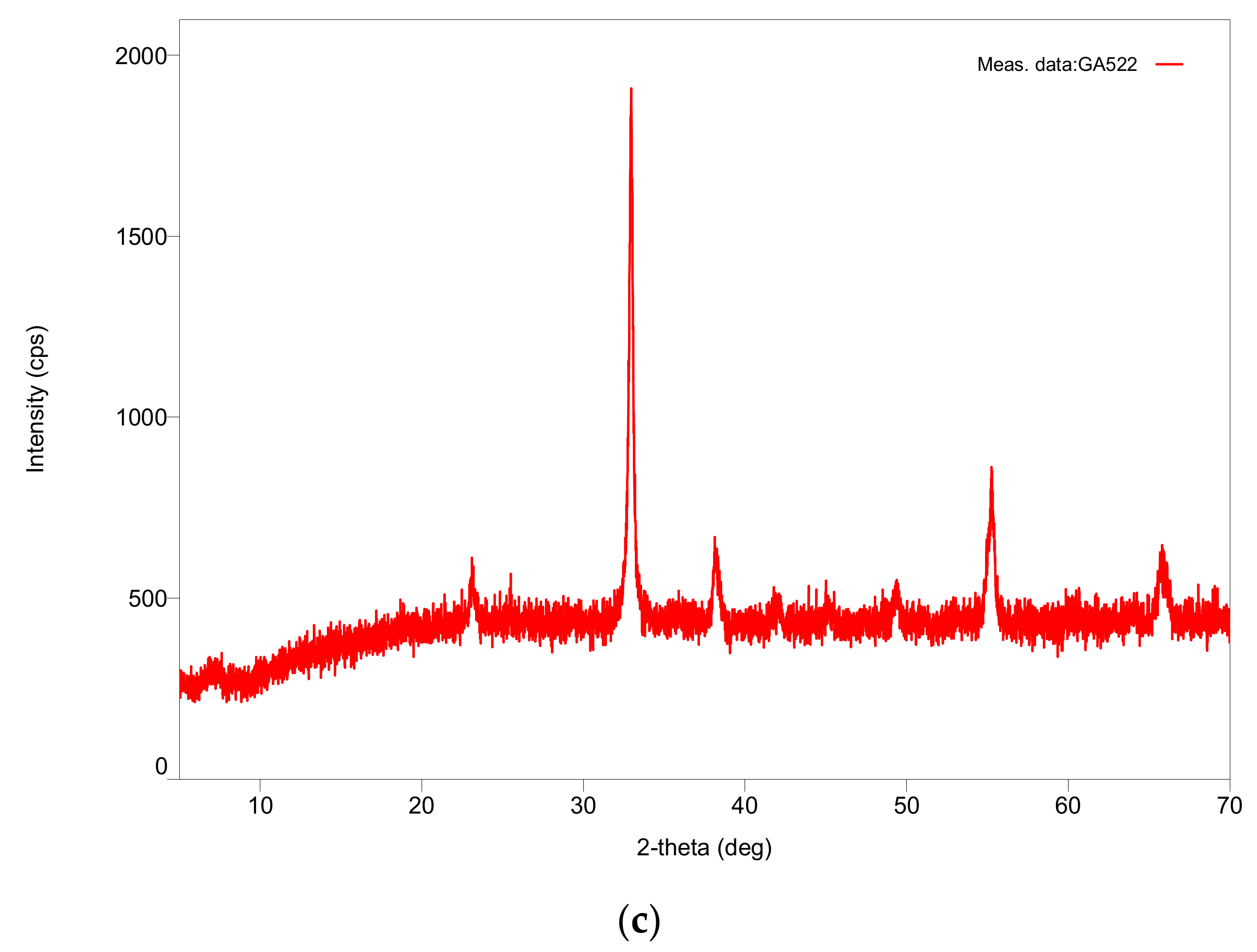
A typical XRD pattern for Co/Si = X system is shown in Figure 4. Figure 4a (X = 1/4; catalyst concentration = 20 mol%) shows that the support SiO2 has a large broad peak at ca. 22°. The remaining diffractions are all associated with Co3O4. As the catalyst concentration increases to 66.7 mol% (X = 2) the broad silica peak is suppressed as seen in Figure 4b. The XRD pattern for Mn/Si = 2/1 catalyst is shown in Figure 4c. Due to the large numbers of manganese oxides (MnOx), the XRD pattern of Mn/Si = 2 contains several diffraction peaks some of which could not be identified. The identification of the peaks for M/Si = 2 (M = Co, Mn) and the corresponding crystallite sizes are shown in Table 5 and Table 6 respectively.
In Co/Si = X catalysts, plasma generation starts when X ≥ 1. However, there were no phase changes detected by XRD when X = 1, but several new phases at 2θ = 25.3°, 32.1°, 36.4° and 38.9° appear when X = 2. The nature of these phases could not be determined, as they were not associated with CoO or Co. The estimate of the crystallite size indicates that some of the phases have a very large size. The crystallite size associated with the dominant peak at 2θ = 36.9° increases with increasing catalyst concentration. The corresponding summary of XRD results for Mn/Si = 2 is shown in Table 6.
As seen from Table 6, diffractions associated with Mn3O4 at 2θ = 17.8°, 32.2°, 44.2°, 50.4°, 58.2°, 59.6°, and 64.6° are absent in all cases when Mn/Si ≥ 1/3; partly because of a possible shift to higher diffraction angles such as from 32.2° to 33.0° for the dominant peak associated with the (103) reflection plane. As in the previous case with Co/Si, a number of new peaks also appear at 23.0°, 42.2°, 45.0°, 49.3°, 55.2° and 65.9°. These additional peaks increase with increasing Mn concentration. Peaks at 2θ = 42.2° and 45.1° can be attributed to MnO and Mn0 respectively [79], indicating that in the presence of microwave generated plasma, Mn/Si supported catalyst precursor decomposition in air results in the formation of Mn3O4 as well as MnO and Mn0. Therefore, the valence of Mn is reduced progressively from +2.67 (Mn3O4) to +2 and 0 to generate heterogeneous domains. However, this conclusion is only tentative because of the presence of weak diffractions, diffraction shifts and interaction between Mn and Si [72]. Weak diffractions also indicate that the new phases do not have significant concentration and such phases may be localized. Therefore, further investigation is carried out using SEM and EDS studies, which confirms this conclusion.

2.8. Effect of Catalyst Concentration on Catalyst Size

Catalyst crystallite size was evaluated for a given reflection plane and tabulated in Table 5 and Table 6 for Co/Si and Mn/Si respectively. It can be seen from these tables that the crystallite size increases with increasing catalyst concentration. There are considerable differences between the crystallite sizes associated with different phases. Therefore, we use the crystallite size of the dominant phase at 2θ = 31.4° for Co3O4 and 2θ = 33.0° for Mn3O4, as the representative catalyst size. Figure 5 shows the variation of crystallite size for M/Si = X and Mn/S supported catalyst as a function of catalyst mol fraction.
It can be seen from Figure 5 that, within experimental error, the crystallite size is independent of the microwave power (as shown previously for Ni/Si system [1]) and it increases linearly with increasing catalyst concentration. We note that the Mn/Si catalyst system prepared by the classical method (incipient impregnation of SiO2 particles method followed by thermal decomposition of Mn(NO3)2) yields catalyst size of ca. 21 nm at mole fraction of 0.15 and 0.21 [72] which are over 100% higher than the present method [1]. Figure 5 also shows that there is no significant difference between Co3O4 and Mn3O4 catalyst size. In both cases, crystallite size is considerably larger than that of Ni/Si catalyst system [1] in which nickel oxide is NiO.
In Figure 5, the catalyst size for the silica supported Co and Mn catalysts containing BaTiO3 (BT) particles (composite catalysts) are also shown (see Section 2.16.1 for details). These catalysts are represented as {M/Si = X}/BT = F when the nominal molar concentration ratio is F = 1/4. It can be seen that the presence of BaTiO3 does not make any significant impact on the catalyst crystallite size based on the dominant reflection.

2.9. Scanning Electron Microscopy (SEM) and Energy Dispersive X-ray Spectroscopy (EDS) Studies

Although XRD-studies indicated that under microwave induced plasma generation, new metal phases appear with reduced valence, the nature and the extent of them could not be determined. In fact, for BaTiO3, the presence of electrical activity in the form of poling was also detected by the intensity reversal of the reflections at 2θ = 44.9° (reflection (002)) and 45.5° (reflection (200)). Using SEM and EDS, plasma discharge activity on the surfaces of pores of the porous spinel and perovskite catalysts can be observed. Here, we first examine the structure of the catalyst at increasing magnifications and using EDS, determine the metal and oxygen distributions, comparing the local values with the theoretical data based on BaTiO3 or M3O4 (M= Co, Mn). Where differences between these two values is clearly large (over 50%) we examine these regions more closely and take SEM images to associate local chemical composition with catalyst morphology. Due to the fact that catalysts are active species, they undergo chemical changes in an oxidative environment through oxygen chemisorption, forming epitaxial oxide layers on surfaces, including M3O4 type of spinels. However, as the main structure obtained is spinel metal oxide itself after processing, these changes are likely to be insignificant. Nevertheless, due to the availability of XRD, SEM and EDS facilities, full characterization was carried out within 1–5 days of catalyst preparation.

2.10. Barium Titanate SEM and EDS

Structural changes in BaTiO3 as a result of prolonged plasma irradiation has been investigated [68] when Dielectric Barrier Discharge (DBD) plasma was generated through the application of high voltage across two electrodes using the equipment described in [14,16,68]. It was shown that although [O]/([Ba] + [Ti]) ratio was initially 1.75 (theoretical value is 1.5 indicating the presence of excess TiO2 as concluded by the fact that [Ti]/[Ba] was also high at 1.07), this ratio was reduced to 1.13 after 80 h on stream during direct CH4 conversion to H2 and higher hydrocarbons. The reduction in lattice oxygen can also be attributed to the oxidation of carbon deposits and CH4.
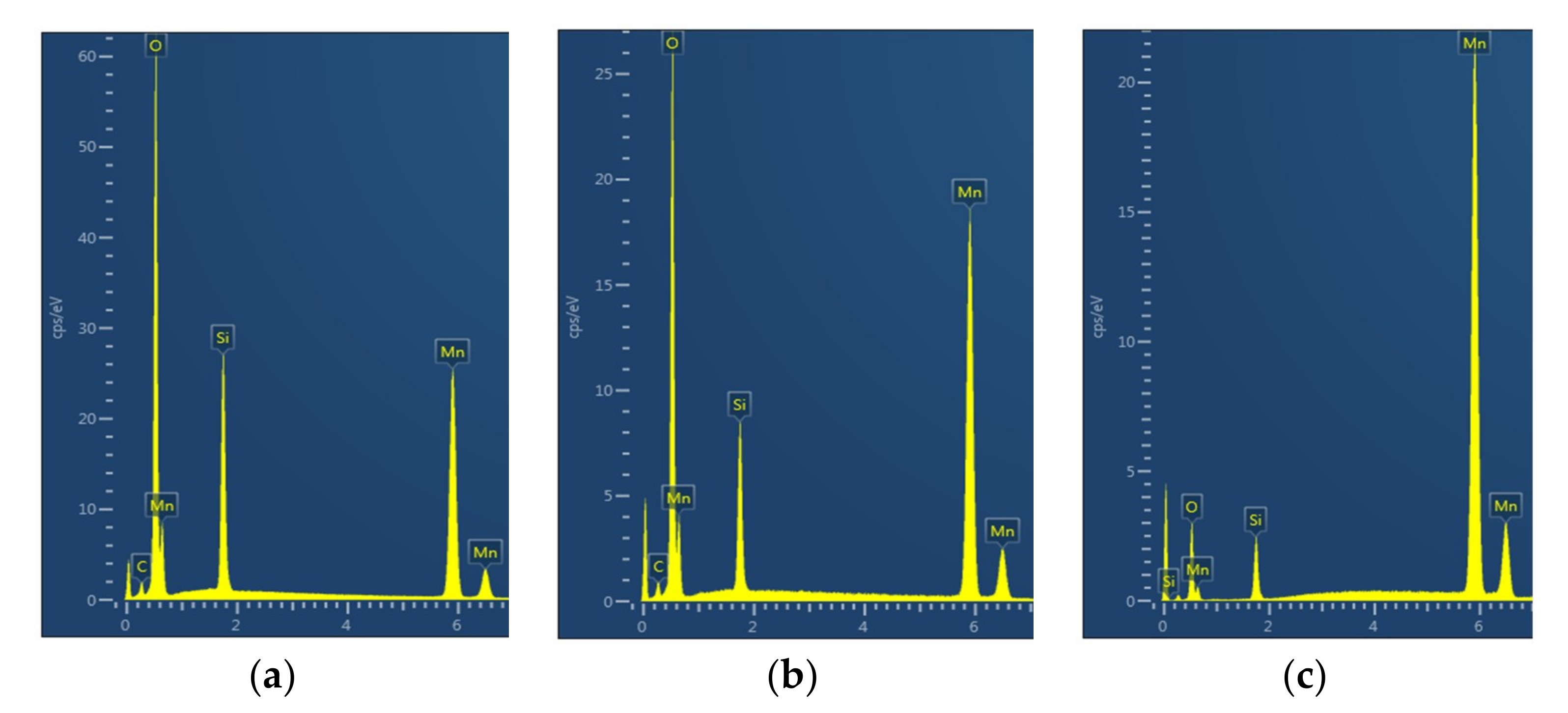
Figure 6 illustrates the Energy Dispersive X-ray Spectroscopy (EDS) analysis of a fresh BaTiO3 particle fracture surface with a large amount of carbon due to coating and impurities. The atomic fractions are; [O] = 0.611; [Ti] = 0.196 and [Ba] = 0.193 with [Ti]/[Ba] = 1.02; and [O]/([Ba] + [Ti]) = 1.57 very close to the theoretical values. The corresponding EDS layered image and EDS of the surface are shown in Figure 6a,b respectively.
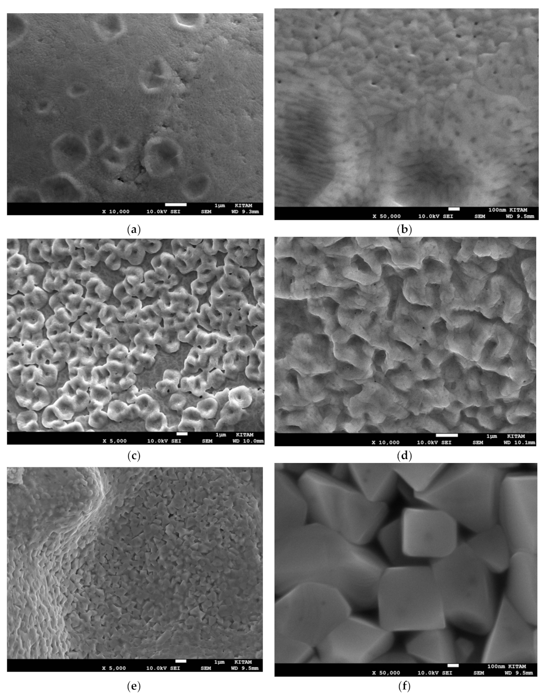
Figure 7 illustrates the fine structure of a plasma exposed BaTiO3 particle at two magnifications (1k and 100k) as a reference. Plasma exposure of BaTiO3 was carried out at 100 W for 50 h in air stream using the experimental set-up described previously [14,16]. Figure 7a shows the presence of large BaTiO3 grains (ca. 100 μm) and the development of layered/herringbone structures which are typical of the tetragonal phase [78,80]. EDX-spectra of these structures in Figure 7 do not indicate any chemical modification such as the presence of nitrogen. Their chemical structure at different locations and magnification are very similar with [Ti]/[Ba] = 1.04 and [O]/([Ba] + [Ti]) = 2.12. On the other hand, when BaTiO3 particles are subjected to microwave irradiation with plasma generation, in addition to the presence of structures similar to those shown in Figure 7, additional crystal structures are observed with highly significant spatial variations reflected in changes in their chemical composition, including the presence of nitrogen.
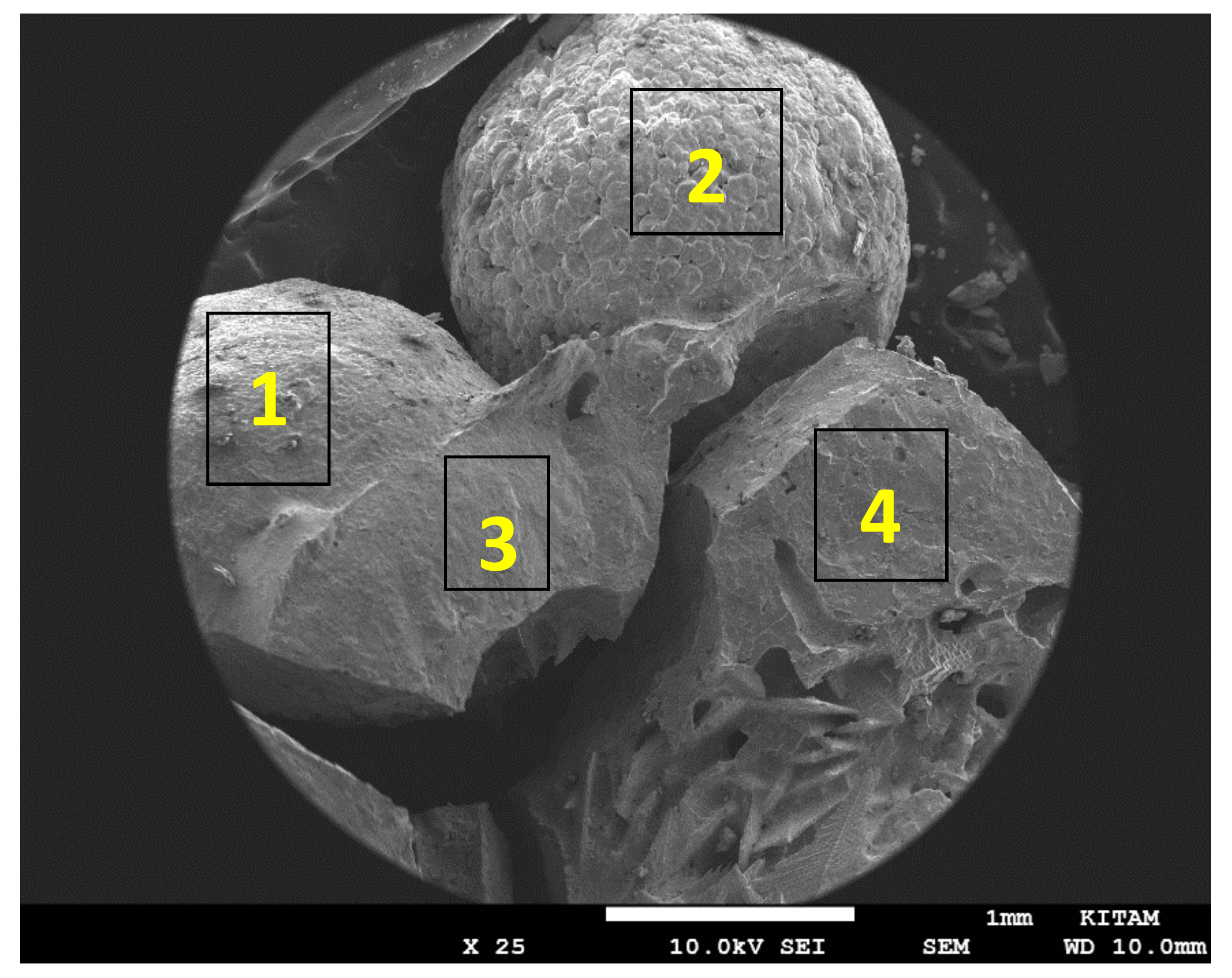
Figure 8 is a SEM image of a collection of 4 BaTiO3 particles (Particles 1–4) with diameter of 3mm, following microwave irradiation in air at 1800 W for 10 min with plasma generation. These particles represent all the features seen in individual particles examined. They show the intact particle surface, fractured particle surface, sintering and the effect of microwave induced plasma generation in BaTiO3 through void formation and electrical treeing (Lichtenberg phenomenon) [81,82] as a result of dielectric breakdown.
The effects of microwave irradiation with plasma generation are described in Figure 9, Figure 10, Figure 11 and Figure 12. Figure 9a is the EDS layered image of Particle-1, showing the distribution of the elements of BaTiO3. It is clear from this image that there are regions where oxygen appears to be in excess compared with the theoretical composition. The presence of excess oxygen is confirmed through the EDX-spectra of the surface, such as shown in Figure 9b as well as the elemental mapping of Ba, Ti and O. EDX-spectrum of the surface yields: [Ba] = 0.123; [Ti] = 0.094; [O] = 0.682; [N] = 0.101 with [Ba]/[Ti] = 1.31 and [O]/([Ba] + [Ti]) = 3.14. These results indicate that the particle surface has Ba-O termination accommodating O-rich BaO3 composition and a negatively charged surface. Here each Ba ion is coordinated by six O ions. It is thus possible to have bonding between N and BaO3 surface structure which accounts for the presence of nitrogen. The distribution of oxygen and nitrogen on this sample, as well as other samples are further investigated below (Figure 12) and it is shown that N-rich and O-rich regions always overlap. It is known that graphene can be doped with nitrogen through plasma treatment to modify its electronic properties [83]. It is therefore not surprising to have nitrogen incorporation into the BaTiO3 lattice through microwave induced plasma.
Figure 10 shows that there are only spots of O-rich regions on the BaTiO3 surface (Particle-2) which is also reflected on the EDX-spectrum of the surface as shown in Figure 10b. This spectrum yields the following molar fractions: [O] = 0.676, [Ba] = 0.165, [Ti] = 0.159 leading to Ba/Ti = 1.03 which is very close to its theoretical value and [O]/([Ba] + [Ti]) = 2.08 which is over 50% smaller than the previous case for Particle-1 (Figure 9b). These results also indicate that the BaTiO3 surface is O-rich due to Ba-O termination. As seen in Figure 10c–e, the BaTiO3 grains are not fused due to low level electrical activity on its surface.
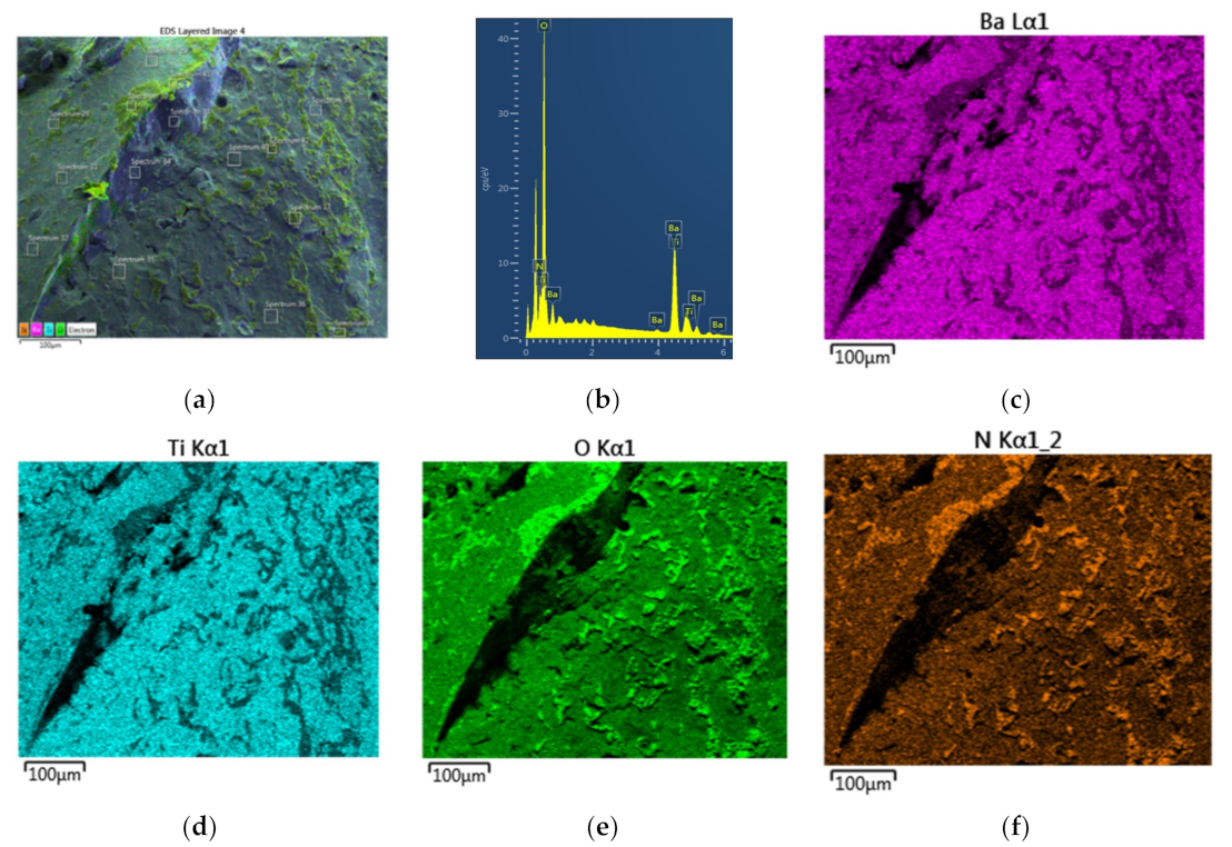
Figure 11 and Figure 12 show how the inner regions of BaTiO3 particles are affected by plasma. Figure 11a is the EDS-layered image of the fracture surface of Particle-4 shown in Figure 8. It shows an electrical treeing image in which regions of O-rich and N-rich regions co-exist. EDX-spectrum yields the following molar fractions: [O] = 0.660; [N] = 0.096; [Ba] = 0.131; [Ti] = 0.112; [Ba]/[Ti] = 1.17 and [O]/([Ba] + [Ti]) = 2.72. These data indicate that the chemical structure in this region is similar to that shown in Figure 9. Electrical treeing is further investigated in Section 2.12.
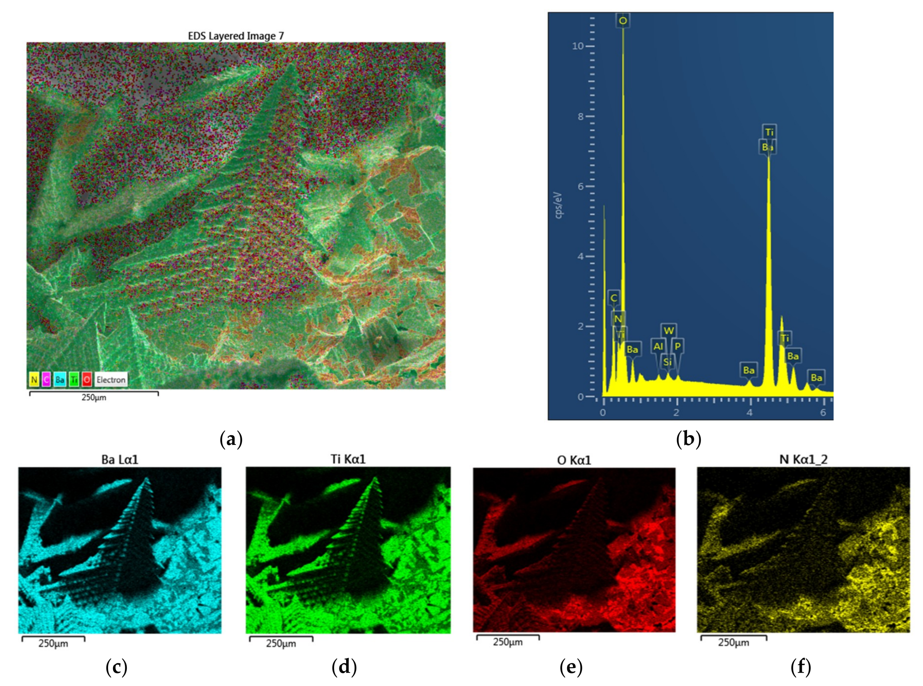
Figure 12 is the summary of the EDS results for the interface region containing both surface of the Particle-1 and the fractured region of Particle-3. EDS layered image for this particle shown in Figure 12a indicates the presence of O-rich and N-rich regions which are superimposed and scattered throughout the sample. The summed map of the EDX-spectrum of the same area shown in Figure 12b reflects the presence of nitrogen which is further illustrated in the mapping of Ba, Ti, O, and N as shown in Figure 12c–f.
In this particle region, EDX-spectrum yields the following molar fractions: [O] = 0.642; [N] = 0.034; [Ba] = 0.176; [Ti] = 0.148; [Ba]/[Ti] = 1.19; [O]/([Ba] + [Ti]) = 1.98 which show that the chemical structure in this region is similar to that shown in Figure 9 and Figure 11. In confirmation with the mapping of oxygen and nitrogen, mappings shown in Figure 11e,f and Figure 12e,f clearly confirms that oxygen and nitrogen co-exist in the same region. As seen in Figure 12a, several local EDX-spectra are also taken in order to examine more closely chemical compositions, in particular the presence and location of nitrogen.
As seen in Figure 12a, the distribution of the elements of BaTiO3 and nitrogen on the surface or fracture surface of the particle is not homogeneous. We therefore investigate the locations where there appears to be: (a) No nitrogen; (b) Low concentration of nitrogen and (c) High level of nitrogen is present. Typical EDX-spectrum for each of these regions are shown in Figure 13 which clearly indicates the highly significant differences in compositions on and within BaTiO3 following the microwave irradiation with plasma generation.
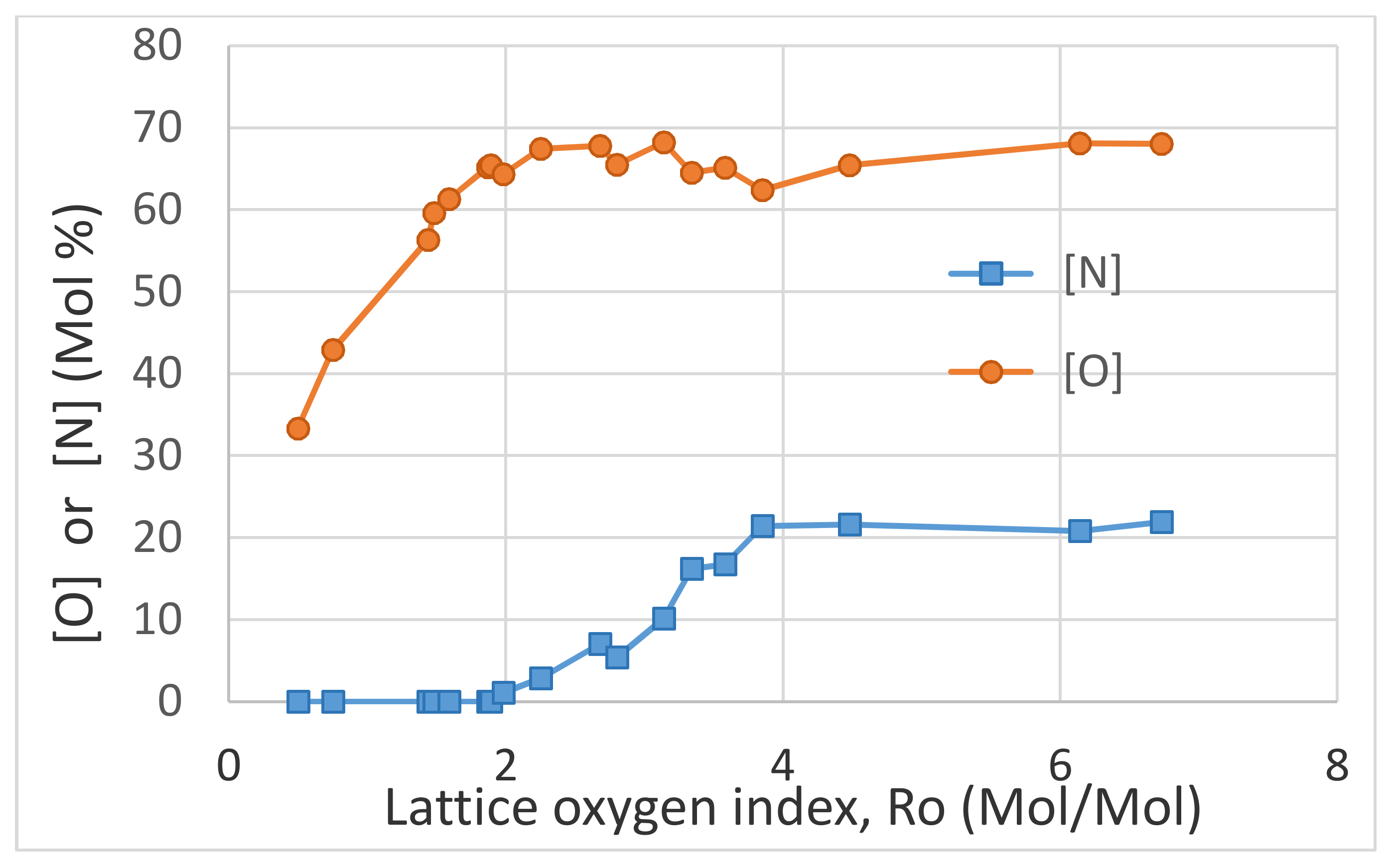
The EDS data is summarized in Figure 14. The oxygen-rich barium terminated characteristics of BaTiO3 surfaces is represented as the molar ratio of oxygen and the sum of Ba and Ti by the lattice oxygen index, Ro defined as Ro = [O]/([Ba] + [Ti]). The stoichiometric value of Ro = 1.5. At Ro = 1.5, [O] = 0.6 as expected. Figure 14 shows that nitrogen is absent when Ro < 2 and its concentration increases rapidly with Ro reaching an asymptotic value of ≈22 mol% when Ro > 4. Oxygen concentration increases with Ro reaching an asymptotic value of ≈68 mol%. As seen in Figure 14, when Ro < 1.5, [O] < 0.6. These results indicate that microwave radiation induced plasma results in structural and compositional inhomogeneity on the surface and within BaTiO3. It is likely that both microwave heating and plasma are responsible for the creation of these changes [68,84,85].
Compared with the XRD-studies, EDS studies yield valuable information about the mechanism of nitrogen oxide formation during microwave induced plasma generation in air. It is clear that this process is a surface phenomenon, rather than a bulk reaction involving lattice oxygen and plasma activated nitrogen. In order to investigate any structural changes in BaTiO3, next, we investigate the Scanning Electron Microscopy of the samples for which EDS studies have been carried out in this section.

2.11. Scanning Electron Microscopy Studies of BaTiO3

Figure 15 and Figure 16 describe the morphological changes in BaTiO3 upon microwave irradiation.
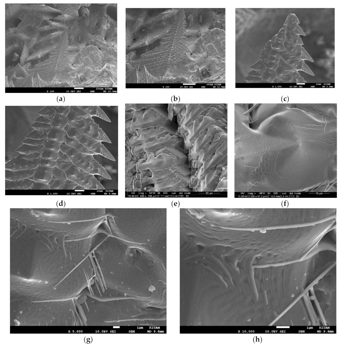
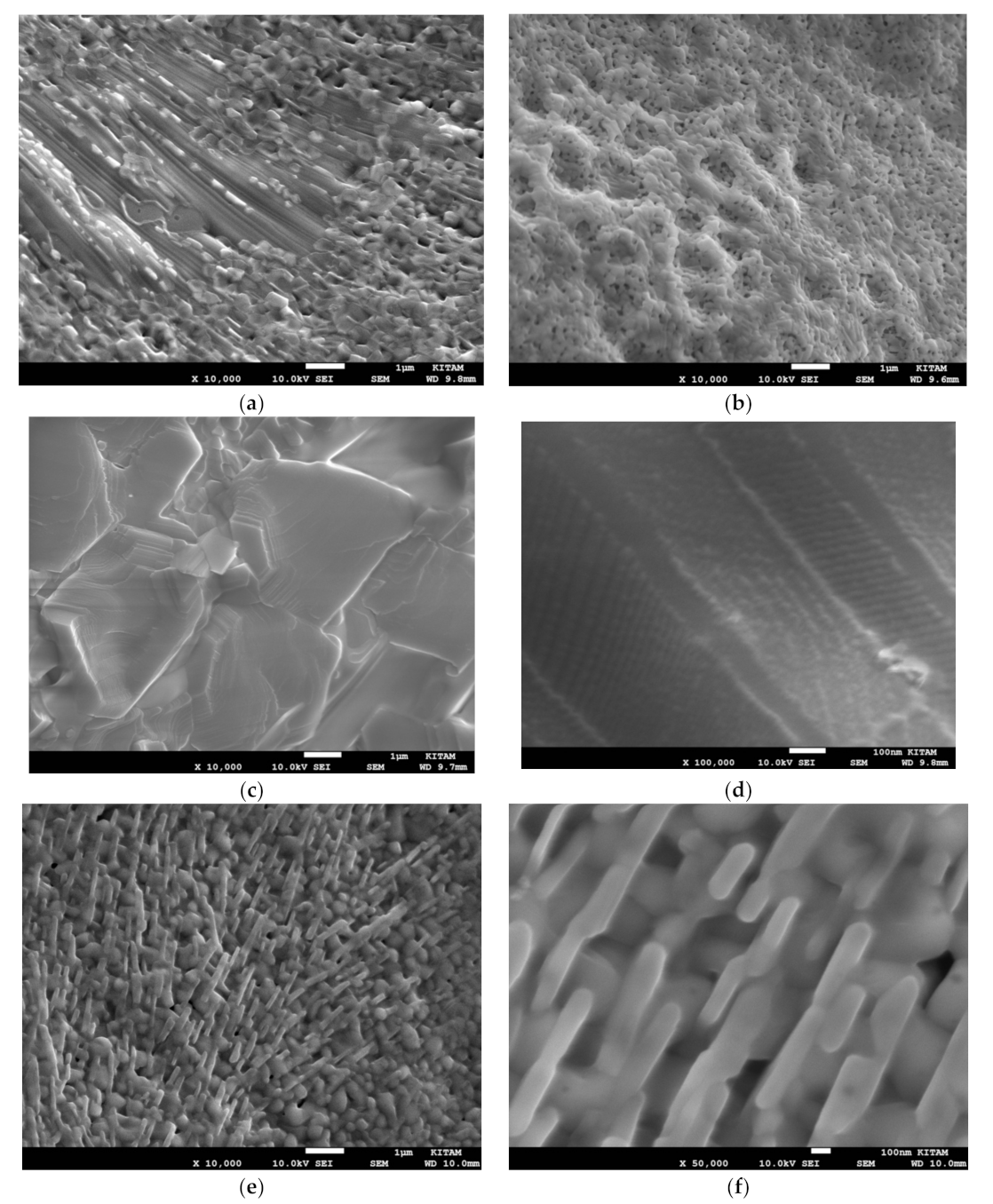
The changes in the crystal morphology in BaTiO3 following microwave irradiation with plasma generation are studied by SEM. Microwave irradiation (carried out at 1800 W for 10 min) appears to result in significant structural changes as shown in Figure 15a–i. These changes include the formation of porous surface skin and phase separation as seen in Figure 15a–c. The fine layered structure in microwave irradiated samples are also different compared with the fresh samples or those which were exposed to plasma only. The fine layered structure in microwave irradiated samples with plasma generation is shown in Figure 15e–i at various stages of morphological change. The layered structure in Figure 15d is similar to that which was observed after prolonged plasma exposure as shown in Figure 7b except that the layer thickness is significantly smaller at ca. 200 nm. Figure 15e also indicates phase separation in the layered structures as well as formation of nano-sized holes. Figure 15f,g shows solid state delamination which is due to internal stresses generated as a result of phase separation shown in Figure 15e as well due to thermal gradient induced during irradiation. Figure 15h indicates the presence of fragmentation of the layered structures which can be attributed to phase separation, Figure 15i is another example of the fragmentation of the laminated structures, which do not appear to have any grains formed by phase separation. This type of layered structure fragmentation can be attributed to the development of high internal stresses due to high temperature gradients. These observations are important in explaining the vast chemical heterogeneity observed in both microwave irradiated BaTiO3 as well as in “composite” catalysts containing large amounts of BaTiO3 which appear to delaminate/ exfoliate/ fragment and subsequently act as a co-support for the catalyst.
Another important structural feature is the formation of electrical trees, as discussed previously. SEM images of these structures are shown in Figure 16a–h. Figure 16a–d represents the image of an electrical tree at various locations and magnifications. The central stalk of the electrical tree consists of closely packed vertebral particles which are also present near the electrical tree as seen in Figure 16a,b. The enlarged views of these structures are shown in Figure 16e,f. In all of these images, there appears to be present several needle-like growths across the entire region. The detail of these needle-like structures are shown in Figure 16f–h. It can be seen from these images that the needle-like structures are essentially thin-narrow plates (ca. 50 nm thick) formed through partial exfoliation of the layered structures. It is also apparent that this process results in the formation of extensive voiding measuring ca. 0.5–1 μm in length and 0.2 μm in width. Both the platelets and these rectangular voids are likely to be useful in the promotion of plasma and catalytic activity.

2.12. Catalyst and Lattice Oxygen Heterogeneity Indices

In the foregoing sections, the generation of plasma during microwave irradiation of the perovskite type catalyst in air and evolution of nitric oxide have been demonstrated using BaTiO3. It is shown that nitric oxide evolution is through the consumption of lattice oxygen which is subsequently replenished by oxygen from air. When the oxygen supply is limited, the lattice oxygen is consumed by the activated nitrogen thus reducing the catalyst oxide. This results in the formation of oxygen-depleted regions interspersed within the catalyst particle which also has regions of high oxygen due to chemical bonding of nitrogen in BaTiO3 resulting in changes in crystal structure. In this section we investigate the effects of microwave irradiation with plasma generation in Co/Si = X catalyst using extensive EDS and SEM studies in order to supplement the XRD investigation carried out in previous sections.
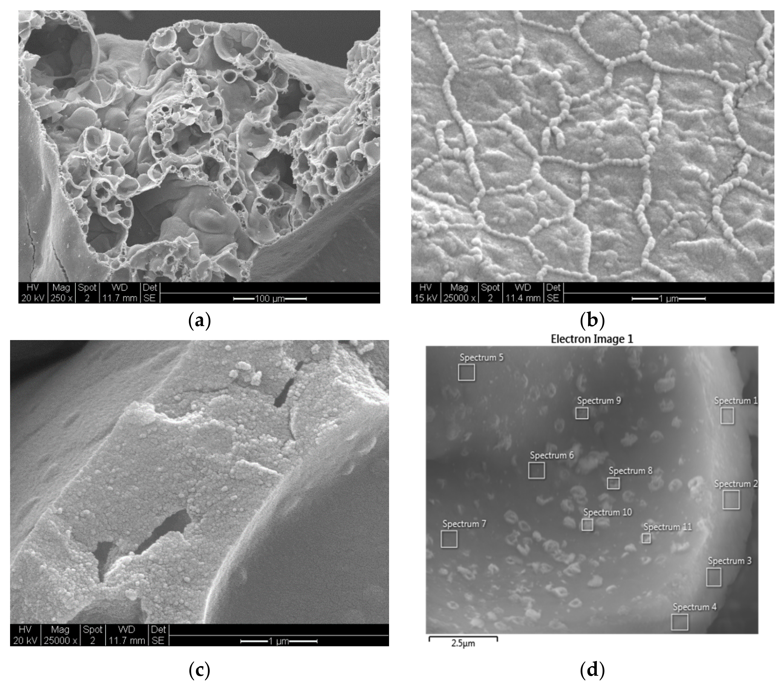
The SEM images in Figure 17a–c illustrate the structure of the Co/Si = 1/4 catalyst in which the overall porous structure, dominant surface structure and the wall structure are shown. The structure shown in Figure 17b indicates the presence of Co-rich domains which disappear if the catalyst is subjected to heat treatment at temperatures ≥ 550 °C. Co/Si = X catalyst has been studied previously [1] when X ≤ 1/4. In this process [1], the organic coating layer on the catalyst is also burnt off.
In the present study, our aim is to investigate the heterogeneity of the catalyst structure which appears to be induced when X > 1/3. This is achieved through EDS and SEM investigations. The spatial heterogeneity of the catalyst chemical structure is carried out by EDS-spot analysis at several locations. Four of the largest and another four of the smallest catalyst (Co) concentration regions are then chosen and the compositions averaged within each group. The catalyst heterogeneity is essentially represented by the standard deviation of the concentrations across the catalyst domain. In the current study, we consider the variation of the Catalyst-Support Index (An) and Catalyst-Oxygen Index (Bn) which are defined as:
An = [M]n/[Si]n
Bn = [O]n/{[M]n + [Si]n}
where M = Co or Mn in the present study. [M], [Si] and [O] represent the molar concentrations of the catalyst (M), support (Si) and oxygen respectively. Here the subscript n = 0, 1, 2, T represents the mean concentrations in the M/Si = X catalyst where the catalyst concentration [M]n is at average (n = 0); or the lowest/minimum (n = 1) or the highest/ maximum (n = 2). n = T represents the theoretical/stoichiometric concentrations and concentration ratios based on the feed M(NO3)m and SiO2 in the catalyst support fluid. Hence, for the supported catalyst system M/Si = X, AT = X and the theoretical catalyst concentration is given by:
[M]T = X/(1 + X)
The average, minimum and maximum values of the catalyst/support ratio (An) and lattice oxygen/catalyst + support ratio (Bn) are denoted by A0, A1, A2, B0, B1, B2 respectively. We define the catalyst heterogeneity (HA) and oxygen heterogeneity (HB) as:
HA = (A2 − A1)/AT
HB = ǀ(B2 − B1)ǀ/BT
The theoretical value of BT requires the knowledge of the chemical structure of the catalyst oxide after the processing of the catalyst and catalyst support fluid. The XRD studies indicated that the dominant structure is spinel, M3O4 (M = Co, Mn) while the support is SiO2. Hence the theoretical oxygen concentration [O]T and theoretical oxygen index BT in Equations (5) and (8) are calculated from:
[O]T = (4X + 2)/(7X + 3)
BT = (4X + 6)/(3X + 3)
The theoretical ranges of AT an BT are 0 ≤ AT ≤ ∞; 2 ≥ BT ≥ 4/3 corresponding to 0 ≤ X ≤ ∞.
The mapping of the constituent elements of the catalyst (Co, Si and O) is carried out by EDS at small magnifications (30–100 x) to obtain the average atomic concentrations in a given location. At least two particles were examined. Afterwards, using the elemental mapping in the layered EDS images, several (usually 20) spot analysis were performed both at catalyst (Co or Mn)-rich and catalyst-depleted areas. In four of the regions with the highest (and the lowest) catalyst, concentrations of the catalyst, support and lattice oxygen were averaged to obtain A0, A1, A2, B0, B1, B2 as well as the catalyst and oxygen heterogeneity indices, HA and HB using Equations (7) and (8) were evaluated.

2.13. SEM and EDS of Cobalt/Silica = X Catalyst Processed under Microwave Radiation with Plasma Generation

In the EDS analysis, carbon concentration was also evaluated for each set of data. Although the catalyst samples are not coated with carbon in SEM-EDS investigations, carbon appears in the silica supported catalyst because silica is coated with epoxy silane (γ-Glycidoxypropyltrimethoxysilane), which contains five oxygen and six carbon atoms after the silanation reaction on the silica support surface. Therefore, in addition to the appearance of carbon in the EDX-spectra, oxygen content was also increased. The effect of silane on measured oxygen concentration decreases with increasing catalyst concentration. Although we have not considered the effect of the organic coating on the catalyst structure, we have corrected the lattice oxygen concentration to take into account of the silane oxygen. We note that the processing temperature is not sufficiently high for the burning of the silane.
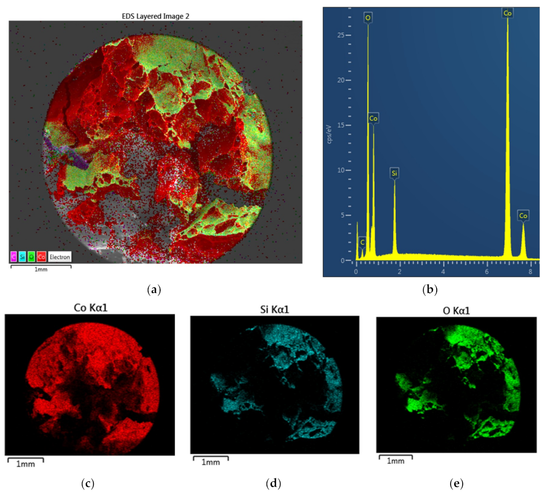
The compositions within the pores and pore walls of the catalyst Co/Si = 1/4 are evaluated using the EDS-images similar to that shown in Figure 17d. Figure 18 illustrates the spatial chemical heterogeneity of the Co/Si = 1 catalyst on the surface of the catalyst which generated plasma during microwave processing at 1800 W, where the total processing time was 1 min. It can be seen from Figure 18a that the particle surface has regions with enhanced cobalt concentration with [Co]/[Si] = 6.17 instead of the theoretical value of [Co]/[Si] = 1.0. The EDX-spectrum is shown in Figure 18b, whereas the mapping of Co, Si and O are shown in Figure 18c–e.
In the absence of any plasma generation during processing, the chemical heterogeneity results from the phase separation which appear as decorations on the catalyst and pore surfaces as show in Figure 17b–d. As shown previously [1], Co/Si = X catalysts show phase separation in the form of decorations illustrated in Figure 17. These decorations cover the pore surfaces, which are otherwise featureless. Therefore, heterogeneity is enhanced when the surface decorations are extensive and dispersed on the featureless background surface. This type of heterogeneity disappears if the catalyst is subjected to heat treatment to burn off the silica surface coating at ca. 600 °C [1], while annealing is taking place.
The heterogeneity in Co/Si = 1/4 in different regions is evaluated from EDS studies and summarized in Table 7. Heterogeneity with respect to Cobalt/Silica ratio (HA) and catalyst lattice oxygen (HB) within the walls, on smooth surfaces and decorated surfaces are shown in Table 7. HA = 0.808 for the walls is similar to the smooth surfaces HA = 0.901 while for the decorated surfaces HA = 0.432. However, if the whole surface is treated as a single entity, HA = 0.932, a value similar to the wall and smooth surface heterogeneity. Heterogeneity in the lattice oxygen (HB) is smaller and the highest heterogeneity HB is observed in the walls and the lowest in the decorated surfaces. Nevertheless, the chemical heterogeneity in the absence of plasma is not significant compared with the case when Co/Si ≥ 1, which is accompanied by plasma generation during processing with microwave irradiation. Therefore, in the subsequent sections, when evaluating the heterogeneity indices, we will only consider the surface rather than the walls, which do not contribute significantly to the catalysis compared with the catalyst surfaces.
The characteristics of the catalysts Co/Si = 1 and Co/Si = 2, which are produced when plasma is generated during microwave irradiation are shown in Figure 18, Figure 19, Figure 20 and Figure 21. Figure 18a–e illustrates the elemental mapping on the surface of a Co/Si = 1 catalyst particle. It can be seen from Figure 18a,c–e that the catalyst surface is highly inhomogeneous and that although cobalt is present across the whole catalyst domain (Figure 18c). Silica (Figure 18d) and oxygen (Figure 18e) rich-domains are closely associated indicating that the oxygen within the catalyst is mainly associated with silica, rather than with cobalt in the form of Co3O4. The average molar concentrations for this particle shown in Figure 18a are: [Co] = 0.413; [Si] = 0.067 and [O] = 0.520 as reflected by the EDX-spectrum shown in Figure 18b. The comparison of the EDX-spectra for Co/Si = 1/4 (Figure 17e) and Co/Si = 1 (Figure 18b) show a large enhancement of the Co peaks due to Co concentration increase, as well as cobalt distribution across the catalyst surface.
Figure 19a–i illustrates the region where the average cobalt concentration is below that shown for the whole particle illustrated in Figure 18a for Co/Si = 1. This is determined from the EDS layered image (Figure 19b) and confirmed by the spectrum of the whole area as shown in Figure 19c. The mapping of Co, Si and O shown in Figure 19d–f indicates the existence of some heterogeneity in chemical composition.
The SEM image of the Co/Si = 1 catalyst surface shown in Figure 19a illustrates the surface structure for this catalyst. It shows two regions that are similar to that shown in Figure 17b,c for Co/Si = 1/4 except that the surface decorations are now extensive. These two structures are further magnified in Figure 19g,i respectively. It has craters surrounded by loosely formed small platelets resulting from the aggregation of particles with size ca. 50 nm. As shown below, these two distinct structures present in Figure 19g,i is associated with low and high cobalt concentrations, respectively. These craters are formed when phase separation takes place within the walls and nano-sized platelets are ejected from the walls.
Figure 19b is also the site of the spot analysis. At this site, based on the spectrum in Figure 19c, the overall composition is [Co] = 0.329, [Si] = 0.109, [O] = 0.562 indicating that [Co] is below the overall composition for the whole catalyst particle shown in Figure 18a. The highest and lowest cobalt compositions are tabulated in Table 8 and compared with the average for this site. Table 8 also includes the concentration data for the whole particle as evaluated from Figure 18. Table 8 indicates that, as the scale of the scrutiny becomes finer, the concentration heterogeneity for the catalyst increases. At high Co concentrations, Si concentration decreases and as a result the catalyst/silica ratio increases. On the other hand, [O]/([Co] + [Si]) remains constant at 1.73. The surface structure at the lowest cobalt concentration is shown in Figure 19g and that with the highest cobalt composition is shown in Figure 19i.
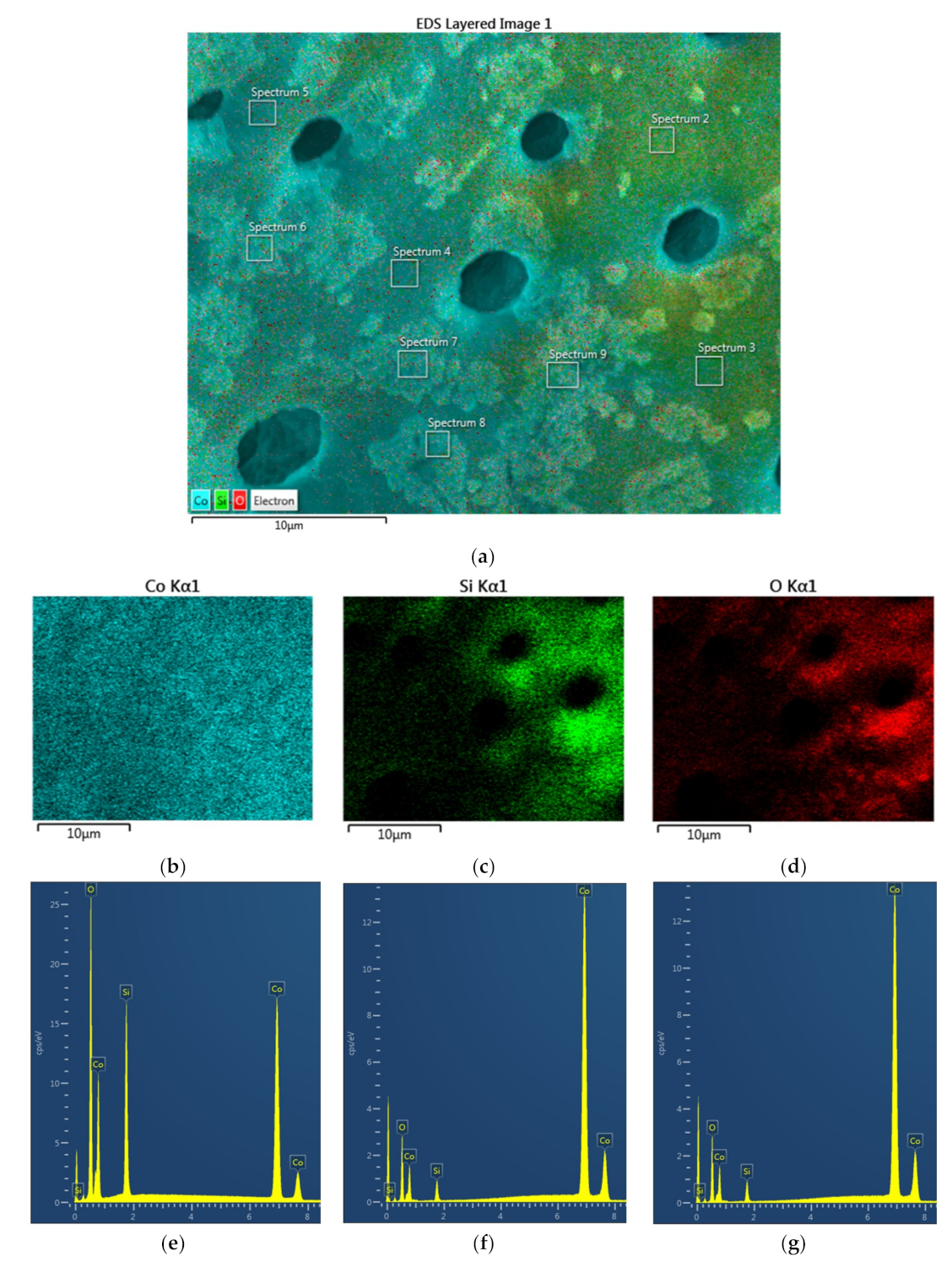
The heterogeneity analysis for Co/Si = 1 catalyst is also carried out in regions where the cobalt concentration is higher or lower than the average cobalt concentration of the catalyst particle, as exemplified in Figure 20a–i. The EDS image of such a location is shown in Figure 20a while the mapping of Co, Si and O are illustrated in Figure 20b–d. Figure 20e–g is the EDX-spectra of the locations where cobalt concentration is minimum (e); average (f) or maximum (g). The EDX-spectrum and the SEM image of the location with the lowest cobalt concentration is shown in Figure 20e,h where the composition is: [Co] = 0.496; [Si] = 0.126; [O] = 0.378. The EDX-spectrum and SEM image of the region, where cobalt concentration is average as evaluated from the EDS layered image, are shown in Figure 20a,f where the composition is: [Co] = 0.720; [Si] = 0.068; [O] = 0.212. Figure 20g,i shows the EDX-spectrum and SEM of the location where cobalt concentration is maximum with composition: [Co] = 0.908; [Si] = 0.018; [O] = 0.074. The proximity of the locations with the lowest and highest cobalt locations are shown in SEM and EDS images of Figure 20j,k where the decorative regions as well as the tips of the craters are rich in cobalt. These cobalt rich regions have nearly 90 mol% phase separated reduced metallic cobalt with a distinct platelet morphology whereas the region with the lowest cobalt consists of fused grains with primary particle size of ca. 50 nm with cobalt still in an oxidized state.
A summary of these results is shown in Table 9, where the variation of the catalyst/support and lattice oxygen heterogeneity indices HA and HB are tabulated as a function of catalyst concentration. It shows that HA increases rapidly from HA = 0.425 when Co/Si = 1/5 to HA = 41 when Co/Si = 1 which is accompanied by plasma generation. Further increase in the catalyst concentration with plasma generation results in reduction in HA. By definition, under thermodynamic equilibrium conditions, in the limiting cases HA → 0 and HB → 0 when [Co] → 0 or 1. However, in practice, equilibrium may take a long time to reach as it requires high heat and mass transfer rates throughout the catalyst. Nevertheless, the current form of the supported catalyst, with its very high porosity and connectivity, allows enhanced heat and mass transfer rates and reaches equilibrium faster compared with non-porous catalysts.
As seen from Table 9, the lattice oxygen heterogeneity index (HB) increases gradually with increasing catalyst concentration, even when plasma is generated. However, this does not mean that the lattice oxygen remains stable. It indicates that the catalyst oxide reduces to metal or low valency oxides with an overall reduction of oxygen concentration across the catalyst surface. The remaining oxygen in the supported catalyst is due to the silica support.
In Figure 21, the results for the catalyst Co/Si = 2 are summarized. The EDS layered image at two magnifications clearly show that the catalyst surface predominantly consists of cobalt, whereas silica is mainly confined to the pore walls, as seen in Figure 21a,b. Elemental mapping of Co, Si, and O shown in Figure 21c–e confirm the above conclusions. EDS image at low magnification in Figure 21a can be used for the evaluation of the average surface cobalt concentration for this catalyst particle whereas the EDS image in Figure 21b has regions of high and low cobalt concentration, suitable for the evaluation of HA and HB.
After identifying regions of below-average and above-average cobalt concentrations, EDS spot analysis was used to determine the sites with the highest and the lowest cobalt concentrations where SEM images were also acquired. These SEM images and the corresponding spectra are shown in Figure 22a–f. Figure 22d–f are the EDX-spectra of the sites with the lowest, average and the highest cobalt concentration respectively. Figure 22a–c are the SEM images corresponding to the lowest, average and the highest cobalt concentrations respectively.
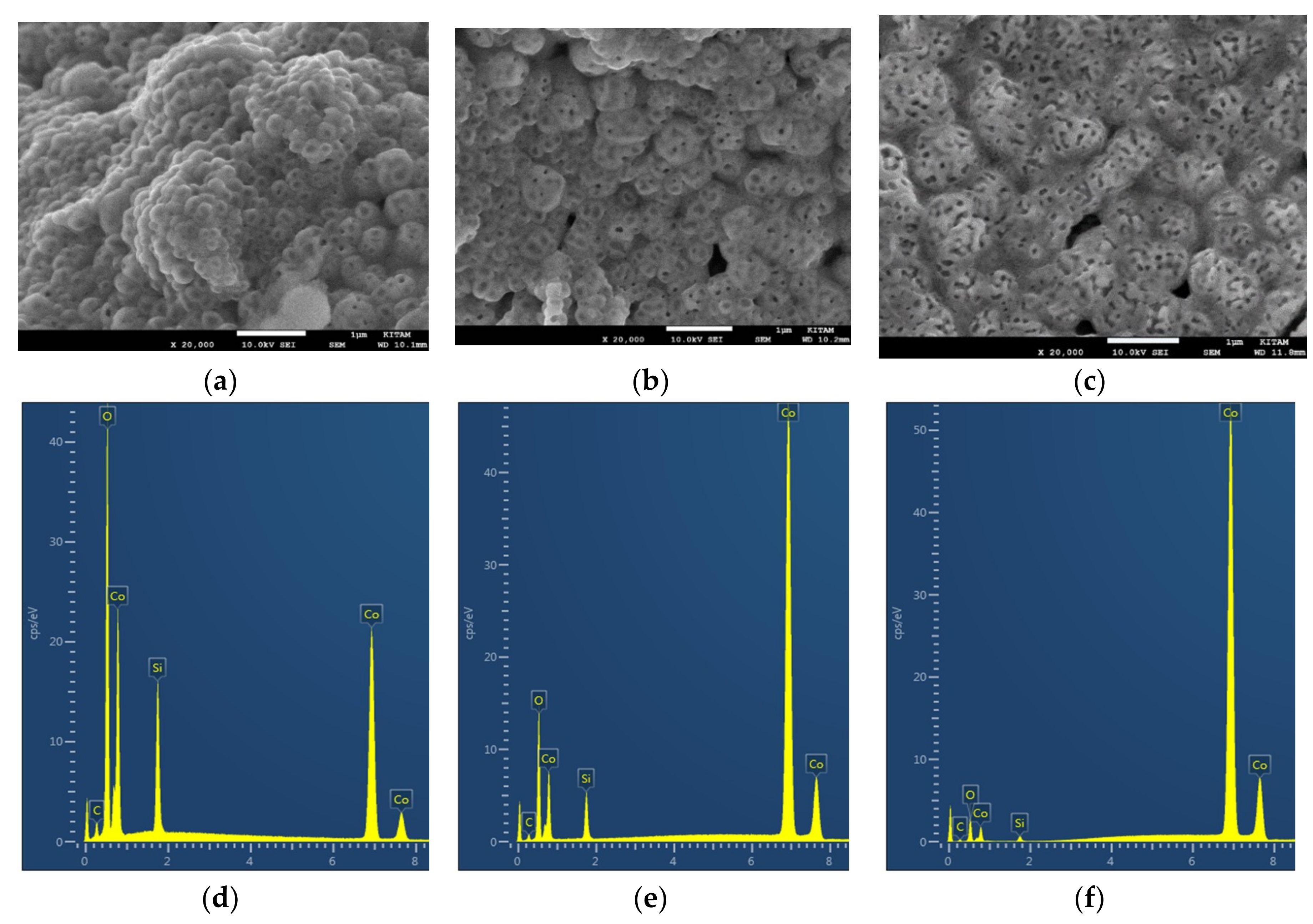
These SEM images indicate that the surface is covered by particles with one or two holes per particle at low cobalt concentration [Co]1 = 0.248 (Figure 22a,d). As cobalt concentration increased, there appears to be a particle agglomeration resulting in approximate doubling of the size and the corresponding increase in the number of holes per particle (Figure 22b,e). At the highest cobalt concentration [Co]2 = 0.933 (97.9 wt%) a large scale particle fusing appears to take place with further modification in particle pore structure (Figure 22c,f). In this high cobalt region, the corresponding Si- and O-concentrations are very low [Si] = 0.007 (0.4 wt%) and [O] = 0.060 (1.7 wt%). It is therefore clear that Co exists mainly as Co0 and the available oxygen is mainly from SiO2. At this location where Co concentration is very high, [Co]/[Si] = 131 (theoretical value = 2) and [O]/([Co] + [Si]) = 0.064 indicating that partial phase separation between Co and Si is present and oxygen depletion is due to Co reduction and subsequent NOx formation. It is interesting to observe that the agglomeration of the single-hole particles in Figure 22a results in multiple-hole agglomerates covering the surface of the pores with holes taking the shape of slits (Figure 22c).
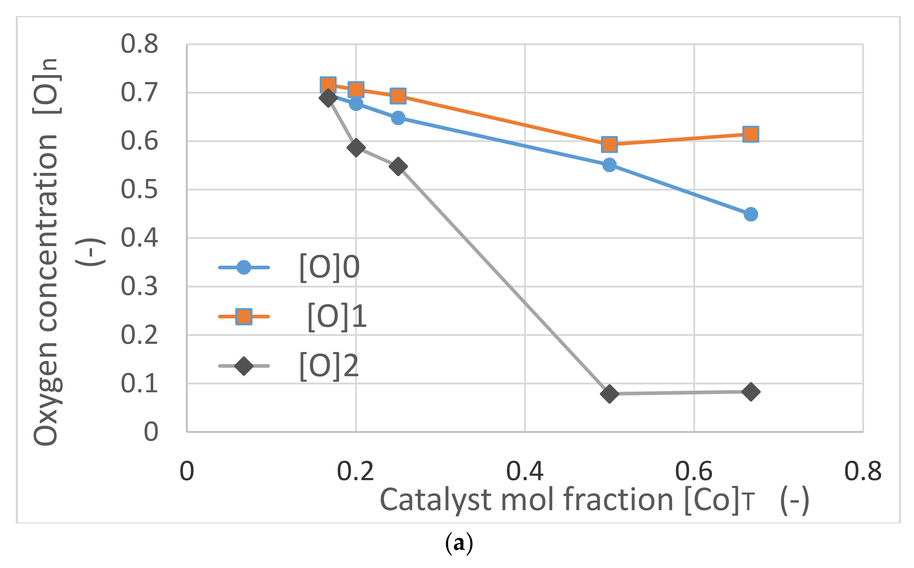
Figure 23 illustrates the characteristics of Co/Si = X catalysts as a function of catalyst concentration [Co]T. The variation of average oxygen concentration [O]0, oxygen concentrations in the regions with the lowest cobalt, [O]1 and the highest cobalt, [O]2 are shown in Figure 23a. It can be seen that the oxygen levels decrease with increasing catalyst concentration in all regions. When [Co]T ≥ 1, which is associated with plasma generation, there is a sharp decay in oxygen concentration in the regions where Co concentration is the highest. In these regions, catalyst oxygen concentration is mainly due to catalyst support and the catalyst is mainly present as Co0.
In Figure 23a, the oxygen concentrations [O]0 and [O]1 are higher than the theoretical concentration [O]T. Freshly synthesized silica supported catalyst is in the form of M3O4/SiO2 and hence the range of [O]T is 0.667 ≥ [O]T ≥ 0.571 corresponding to 0 ≤ [Co]T ≤ 1. This indicates that silica supported catalyst has anionic silica clusters [86] in the form of SipOq where p = 3 – 8 and (2p − 1) ≤ q ≤ (2p + 2). Such clusters can react with water [86] to form SiO3(OH). Therefore, the presence of localized excess oxygen in the region with low cobalt and high oxygen regions ([Co]1 and [O]1), excess oxygen is ca. 10% for Co/Si = 1/5, which can be explained by SiO2 cluster formation.
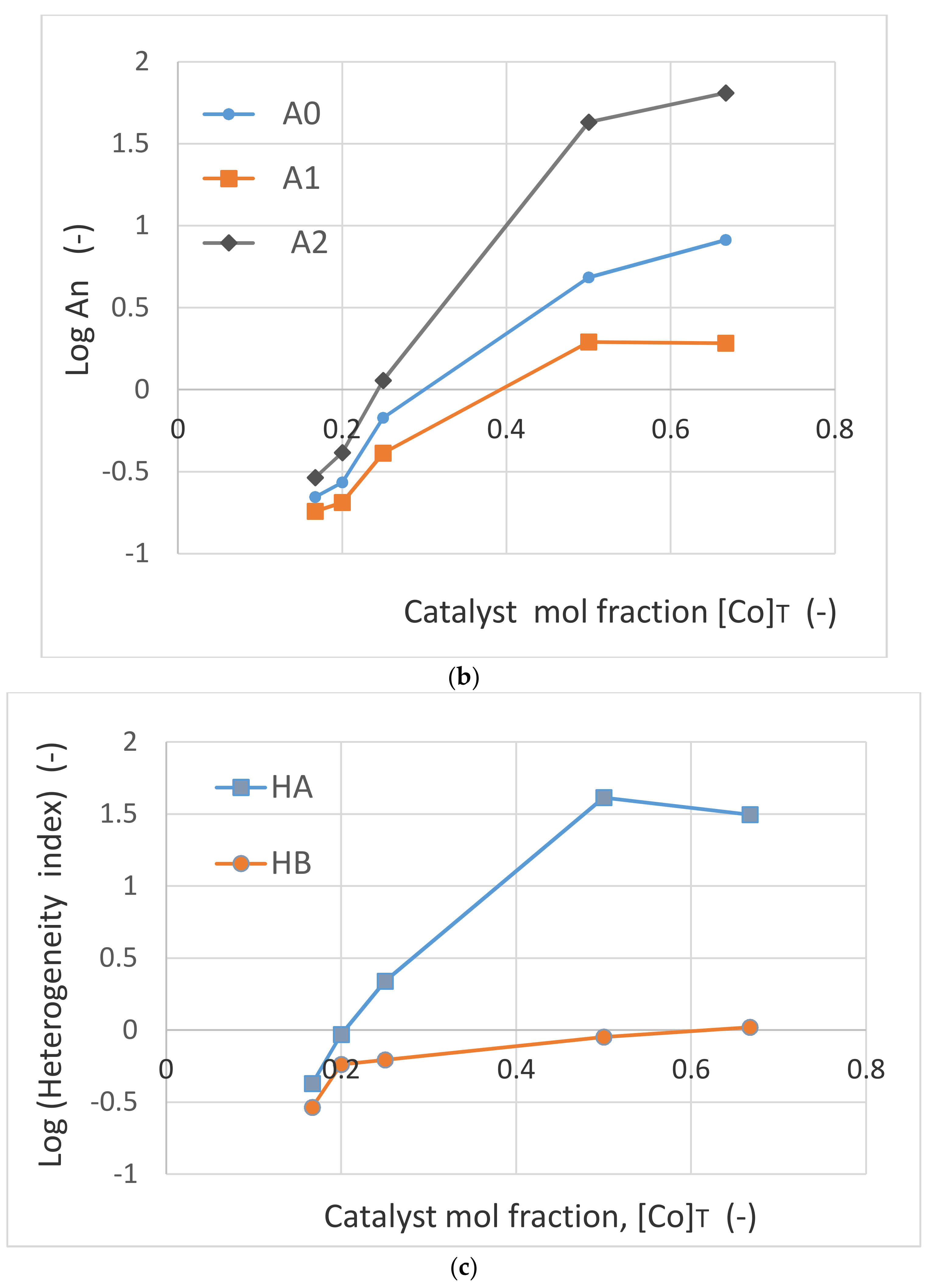
Figure 23b represents the variation of catalyst/support ratio (An = [Co]n/[Si]n) as a function of catalyst concentration [Co]T at three locations corresponding to n = 0, 1, 2. Due to the spread of the data, the results are shown on a logarithmic scale for An. It can be seen that the cobalt/silica concentration ratio increases rapidly and plasma is generated when [Co]T ≥ 1. It can be concluded that when the catalyst is reduced to Co0, the catalyst surface also becomes significantly richer in Co0 and the heterogeneity becomes more significant.
Figure 23c shows the variation (in logarithmic scale), of the catalyst and oxygen heterogeneity indices, Log (HA) and Log (HB) as a function of feed cobalt concentration [Co]T. Within the experimental range of [Co]T, oxygen heterogeneity index increases modestly compared with the cobalt heterogeneity index which increases by nearly 100-fold when [Co]T is increased from [Co]T = 0.167 to [Co]T = 0.5, followed by a decrease with further increase in catalyst concentration.

2.14. SEM and EDS study of Manganese/Silica Catalyst Processed under Microwave Radiation with Plasma Generation

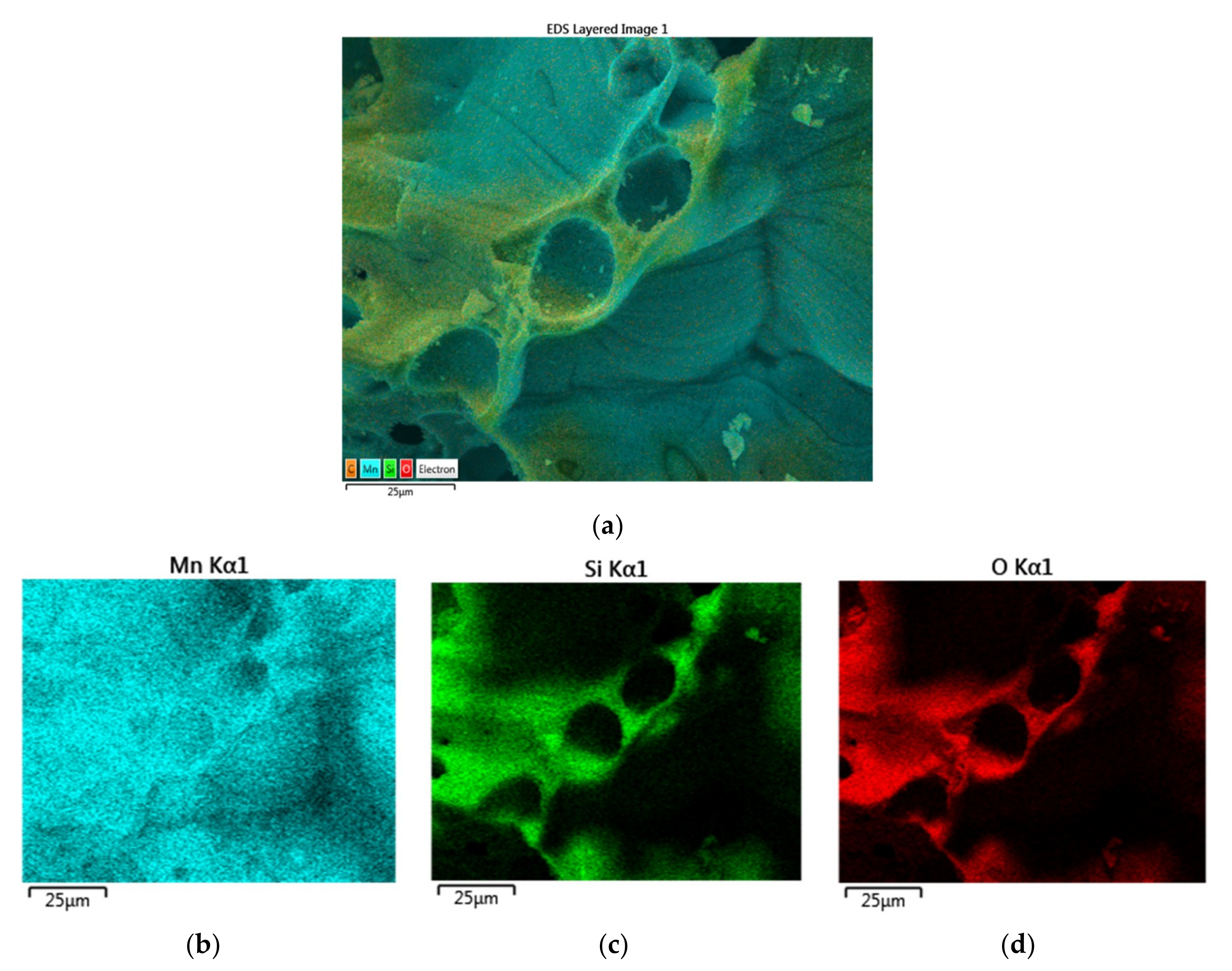
The SEM and EDS analysis carried out for Co/Si= X (X = 1, 2) is replicated for Mn/Si = X (X = 1, 2) catalyst. For Mn/Si = 1 catalyst it is found that the structural and chemical heterogeneity of this catalyst, is relatively low compared with Co/Si = 1 catalyst. Figure 24a–d illustrates the morphology of Mn/Si = 1 catalyst. The catalyst particle surface as well as the surface of the pores consist of ca. 500 nm sized fused particles, while the walls contain similar size closely packed discrete particles. The electron images of the catalyst site shown in Figure 24a is illustrated in Figure 25a–e, which indicates that the Mn, Si, O distributions are inhomogeneous but not as marked as the inhomogeneity in Co/Si = 1 catalyst. The overall composition of the region shown in Figure 25a represents the average Mn concentration with: [Mn]0 = 0.384; [Si]0 = 0.149; [O]0 = 0.467.
On the other hand, the physical and chemical heterogeneity in Mn/Si = 2 catalyst is highly significant, as shown in Figure 26. Figure 26a,b illustrates the electron image of two sites at two different magnifications. Figure 26a shows the presence of chemical heterogeneity on the particle surface while Figure 26b illustrates the local heterogeneity in the inner pore walls and surfaces. The elemental mapping of Mn, Si, O corresponding to the electron images are shown in Figure 26c–h respectively. These figures show that Mn is present throughout the sample while Si and O are localized especially within the pore walls. Figure 26a is used to determine the average concentrations while Figure 26b is used to determine the locations of the below- and above-average Mn concentrations in evaluating the heterogeneity indices, HA and HB as well as in evaluating the catalyst morphology as a function of Mn concentration.
Figure 27a–c shows the EDS-spectra at three locations representing: (a) the average, n = 0; (b) the lowest, n = 1; and (c) the highest, n = 2, Mn concentration for Mn/Si = 2 catalyst. Similar to Co/Si = X it was observed that carbon was not present in the regions with the highest Mn concentration. Also shown are the corresponding results when the fresh catalyst was further subjected to microwave irradiation for 1 extra minute at a power rating of 1800 W.
Molar concentrations of [Mn]n, [Si]n, and [O]n as well as catalyst/ support ratio, An, catalyst oxygen capacity Bn together with the corresponding heterogeneity indices HA and HB are tabulated in Table 10. It can be seen from Table 10 that the highest Mn concentration ([Mn]2 = 0.732) is not as high as that observed for Co ([Co]2 = 0.903) for Co/Si = 2 catalyst even after an extra microwave irradiation when [Mn]2 = 0.815. As a result, the catalyst/support heterogeneity index HA for Mn/Si = 2 is significantly lower than those observed for Co/Si = 2. Lattice oxygen heterogeneity index HA for Mn/Si = 2 is slightly higher for Mn compared with Co. This can be attributed to the fact that Mn has several more oxidation states than Co.
The morphological variations in catalyst (Mn/Si = 2) structure as a function of Mn, Si, O concentrations are shown in Figure 28. Mn/Si = X catalyst particles are porous with a large surface area exposed to air during processing. Below this surface skin, pores are present, with pore wall thickness of ca. 1 μm. Both the catalyst skin and the pore surfaces have morphologically distinct structures depending on the plasma exposure (time span and intensity) during processing while the pore walls have proto-structures but mainly consist of nano-sized porous spheres. The porous wall structures are common in all the catalysts described here and previously [1].
Figure 28 shows the surface skin structure as a function of local catalyst concentration. It can be seen that as Mn concentration increases (with corresponding decrease in Si and O), surface structures (decorations) appear with increasing dominance. Figure 28a,b shows the background silica rich surface layer (with composition [Mn] = 0.201; [Si] = 0.115; [O] = 0.684) which is porous and has nano-sized (ca.10–20 nm) structures especially within the surface pores.
The observed surface decorations are associated with higher Mn concentrations as seen in Figure 28c where [Mn] = 0.317; [Si] = 0.075 and [O] = 0.606. As a result of stronger plasma generation, surface shown in Figure 28d consists of sintered particles with very large Mn and smaller oxygen concentration with composition [Mn] = 0.772; [Si] = 0.059; [O] = 0.169. The dominant structure on the surface of the inner pores of Mn/Si = 2 catalyst, the surface is covered ca. 500 nm crystals with partial sintering and enhanced Mn concentration with composition: [Mn] = 0.843, [Si] = 0.023 and [O] = 0.134.
The effect of further microwave irradiation and plasma generation is illustrated in Figure 29a–f. Here, the fresh Mn/Si = 2 catalyst was microwave irradiated for another 60 s at 1800 W with plasma generation to obtain Mn/Si = 2* catalyst. The surface structures change significantly while Mn concentration increases as seen in Figure 29a–d. The concentration of Mn rich decorations across the surface increases with further microwave radiation. Sintering and porosity of the surface decorations increases with pore size ca. 100–200 nm as seen in Figure 28a–d. At the highest Mn concentration (when [Mn] = 0.840; [Si] = 0.023; [O] = 0.137) the nano-structure of the material has a layered configuration shown in Figure 29d. In fact, the fine structure of these crystals is similar to that of microwave irradiated BaTiO3 structure (see Figure 15 and Figure 16) except that in Mn/Si = 2 catalyst, the grains are smaller (ca. 10 μm) and the layers are thinner (ca. 10 nm) compared with BaTiO3 grain layers of ca. 100 nm. Some of the cuboidal nano-crystals observed (see Figure 28e,f) on the pores of the fresh Mn/Si = 2 catalyst appear to be partially transformed into ca. 100 nm diameter and ca. 500 nm long rods (with composition: [Mn] = 0.804; [Si] = 0.019; [O] = 0.177) as seen in Figure 29e,f. These results indicate that it is possible to obtain several different catalyst morphologies through microwave induced plasma. These structures are likely to be catalytically more active under plasma.

2.15. Catalyst Reduction, Surface Transition from Spinel to Silicate Perovskite (MSiO3) Structure and Formation of Olivines (M2SiO4)

The foregoing analysis of the spinel and perovskite catalysts primarily investigated by EDS analysis indicate that within the same catalysts there exists reduced and oxidized domains with distinct crystallite structures separated by micrometer-scale distances. Therefore, such catalysts can simultaneously catalyze two sequential chemical reactions forming a micro-scale chemical-looping system.
In many cases, after synthesis, the catalyst oxides need to be reduced in hydrogen stream at ca. 500–600 °C before use. Clearly, the present technique can be used as a means of catalyst reduction. Furthermore, in plasma reactors, high concentrations of metal catalysts are not tolerated due to electrical discharges, whereas in the current technique, plasma is generated at high metal catalyst concentrations. This also provides a cost advantage because cheap catalysts at high concentrations can economically replace expensive catalysts.
It is often assumed that the support in supported catalysts is inert and does not undergo any chemical change during catalyst preparation or chemical reaction. This is indeed highly desirable as such chemical changes could result in catalyst deactivation and unpredictability. The supported catalyst system introduced by the author [1] does appear to satisfy this criterion partly because, although they have been produced using microwave (or indeed using UV or thermal energy) no plasma generation was observed even when Nickel/Silica system (Ni/Si = X) was synthesized at high Ni concentrations, X = 2. The undesirability of catalyst activation loss due to chemical reactions during preparation or catalytic reactions would be circumvented if the reaction media also helped catalyst renewal. The reversibility of catalyst chemical/physical structure would also provide certain advantages as discussed next.
As shown previously, in M/Si = X (M = Co, Mn) at high catalyst loadings when X ≥ 1, extra reflections appear in the XRD spectra (See Section 2.7). These extra reflections can be explained by the transfer of catalyst spinel structure, M3O4 (M = Co, Mn in the present case) to silicate perovskite structure MSiO3 and/or olivine structure M2SiO4 at high catalyst concentration with microwave induced plasma generation. The preparation and XRD studies [87,88,89,90,91,92] of MSiO3 and M2SiO4 show that several of the emergent reflections in M/Si = X (X ≥ 1) catalysts are present in MSiO3 and M2SiO4 compounds. This explains the formation of surface decorations shown in both Co/Si = X and Mn/Si = X catalysts when X ≥ 1. As shown in Figure 24, Figure 25, Figure 26, Figure 27, Figure 28 and Figure 29, such structures are dispersed in the main catalyst structure which results in high oxygen (HB) and catalyst (HA) heterogeneities.
Chemical and physical heterogeneities are formed as a result of microwave induced plasma. Therefore, this combination can be used to achieve surface modification. MSiO3 and M2SiO4 compounds provide an alternative and more efficient anode for lithium ion batteries which represent the most common electrical energy storage technology. Currently, anode of these batteries is made from intercalating graphite. In order to enhance anode energy density capacity, metal silicates such as M2SiO4 (M = Co, Fe, Mn) have been studied [87,88,89,90,91,92].
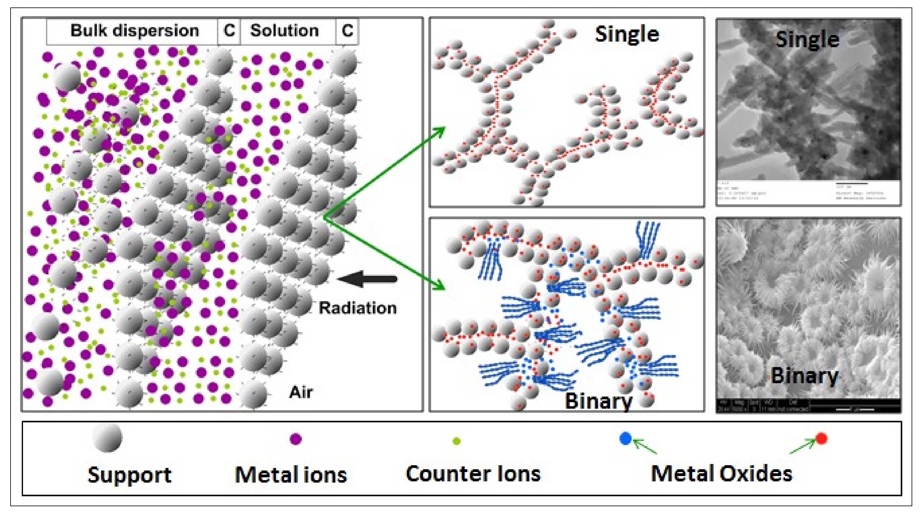
2.16. Binary and Composite Catalysts for Plasma and Related Synthesis

The foregoing analysis of the spinel and perovskite catalysts primarily investigated by EDS analysis indicate that within the same catalysts there exists reduced and oxidized micro-domains with distinct crystallite morphology, separated by micrometer-scale distances. Therefore, such catalysts can simultaneously catalyze two chemical reactions thus forming a micro-scale chemical looping system. Furthermore, the applications of the catalytic microwave induced plasma can be expected to be extensive as it offers a simpler catalytic plasma reactor design without the need for high voltage and electrodes to generate plasma. Such attributes of the plasma generating catalysts can be enhanced through binary catalysts which can promote sequential reactions and plasma generation. In this section, we briefly exemplify binary catalyst systems which can further promote catalytic reactions when the rate determining steps require different catalysts in close proximity as described recently [57]. Detailed study of such systems is the subject of another study.

2.16.1. Co/Si = 2 and BaTiO3 Composite Catalysts

We have recently shown that the combination of BaTiO3 and silica supported catalyst, Ni/Si = 1/4, increased nitrogen conversion in catalytic non-thermal plasma synthesis of ammonia in a packed bed reactor [16]. Ammonia yield reached maximum (at 17% with ammonia concentration of 9%) when 50–50 (by volume) of BaTiO3 particles were mixed with Ni/Si = 1/4 catalyst [16]. This was attributed to maintenance of plasma by BaTiO3 across the reactor and near the Ni/Si catalyst sites. The current findings support this conclusion as we have seen that plasma activity was observed within BaTiO3 pores. Furthermore, it was shown that larger size BaTiO3 packing was more efficient [14,16,68,93]. It is therefore possible to design new catalyst systems where BaTiO3 (or other high permittivity materials) can be dispersed into the M/Si = X catalyst [3] or BaTiO3 particles can be coated with a catalyst. It is probably best if M/Si = X catalyst and BaTiO3 mixtures formed co-continuous structures so as to utilize the size effects observed in BaTiO3 promoted plasma generation [94] and morphological effects observed for catalysts [94,95,96].
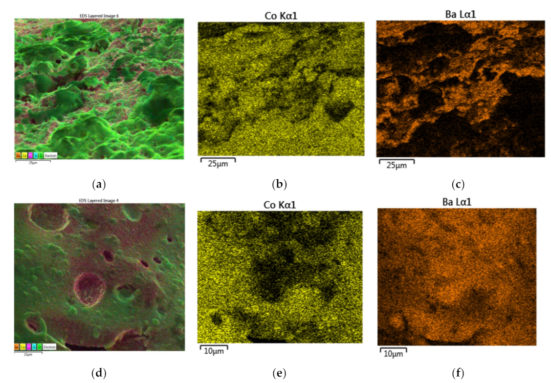
In these studies, we used powdered BaTiO3 particles in the size range of 10–53 μm with an average particle size of D50 = 32 μm. They are obtained by crushing fresh 3 mm diameter BaTiO3 spheres and sieving to obtain particles in the specified size range. These particles (15 g) were added to 10 mL of the catalyst and silica support precursor fluid which was subsequently microwaved at 1800 W. The resulting catalyst system yields a nominal Co/Ba ratio of 1/4. The resulting composite (or BaTiO3 filled) catalyst system is denoted as {M/Si = X}/BT = F where M = Co; X = 2 and F = 1/4 in the present case.
The mechanism of supported catalyst formation is through a repeated thin film formation and collapse during microwave irradiation [1] when water is evaporated and a porous catalyst-support precursor solid is obtained in which the catalyst precursor subsequently undergoes decomposition to form catalyst oxide. As the catalyst-support precursor fluid film has low viscosity (both simple shear and extensional viscosities), the flotation of BaTiO3 particles cannot be expected to take place within the films formed during evaporation. However, this situation changes as water is evaporated from the precursor fluid and silica network is formed in the films. Furthermore, small particles can be trapped between the collapsing films thus providing local defects in the final catalyst. Nevertheless, as BaTiO3 particles produce microwave induced plasma, we can expect some effect on the characteristics of the catalysts produced in the presence of BaTiO3 particles. It is known that not only the catalyst activity is maintained in plasma processing but the catalyst activity can be enhanced when they are produced under plasma [74,94].
In order to understand the interactions between BaTiO3 particles and the catalyst Co/Si = 2, we also carried out synthesis using 1mm BaTiO3 particles. In this case most particles were not fragmented and could be recovered with Co/Si = 2 catalyst around them. Figure 30a–c shows the surface EDS image as well as Co and Ba distributions of a large BaTiO3 particles (diameter 1mm). This figure indicates that Ba distribution is not in discrete form occupying large domains but in a fragmented state. The corresponding EDS image and Co and Ba distributions in the bulk of the {Co/Si = 2}/BT = 1/4 composite catalyst (with initial BaTiO3 particle size range of 10–53 μm) are shown in Figure 30d–f. Large discrete particles of BaTiO3 were not observed in these composite catalysts. It is most likely that during the evaporation of water, high intensity microwave energy causes very rapid temperature rise, creating a large temperature gradient across BaTiO3 particles which in turn results in internal stresses, leading to delamination, fracture and fragmentation of BaTiO3 particles. Earlier studies on BaTiO3 microwave irradiation with plasma generation showed the presence of delamination and fragmentation (see Figure 15). It appears that if the BaTiO3 particles are too large, fragmentation takes place on the surface of the particles which remain intact otherwise.
Figure 30a–c shows the deposition of Co/Si = 2 catalyst on the surface of a 1 mm BaTiO3 particle. The EDS analysis of this region yielded the following molar composition: [Co] = 0.187; [Si] = 0.101; [Ba] = 0.026; [Ti] = 0.028; [O] = 0.658. The data show that, at this location, [Co]/[Si] = 1.85; [Ba]/[Ti] = 0.929 and [Co]/[Ba] = 7.19 indicating that the BaTiO3 surface is well covered with Co/Si catalyst, while the oxygen concentration at [O] = 0.658 is slightly above the theoretical value of 0.590 due to enhanced oxygen in irradiated BaTiO3.
Figure 30d–f illustrates surface of the composite catalyst with small initial BaTiO3 particles (10–53 μm). In this case, [Co]/[Si] = 1.52; [Ba]/[Ti] = 0.938; [Co]/[Ba] = 1.36. [O] = 0.676 which is similar to the previous case above. Figure 30d–f indicates that BaTiO3 is not distributed as a particulate with size > 10 μm but as sub-micron to nano-sized particles.
In order to understand the interactions between BaTiO3 particles and the supported catalyst, Co/Si = 2, further examination of a large particle was carried out. This particle appears to be fractured from an initial diameter of 1 mm. These 1 mm BaTiO3 particles were placed in the catalyst/support precursor fluid in order to detect their presence after processing. Figure 31 is the EDS image of a large fractured BaTiO3 particle (ca. 0.5 mm) dispersed into Co/Si = 2 catalyst. It can be seen that adhesion between BaTiO3 and Co/Si = 2 catalyst phases is present. After obtaining the EDS-spectrum of the area shown in Figure 31a, several spot analyses were performed to obtain the heterogeneity of the composite catalyst. Four locations are chosen as representative catalyst characteristics as shown in Figure 31b–e.
Figure 31a shows that the BaTiO3 particle has surface covering of Co/Si catalyst and is surrounded by the porous Co/Si catalyst. The morphology (as evaluated by SEM) of the four locations where the EDS spot analysis were performed are also shown. From the EDS analysis of the locations (b–e), the compositions are determined and summarized in Table 11.
It can be seen from Figure 31 and Table 11, that the surface of the BaTiO3 particle shown in Figure 31a is covered with the Co/Si catalyst with varying levels of Co/Ba ratio. Referring to Table 11, at location (b) in Figure 31b, Co/Ba ratio is very low and Co/Si catalyst is present as ca. 10 nm domains. In this region, the presence of nitrogen was detected. At higher levels of Co/Ba (Location(c)), Co/Si catalyst appears to fill the valleys between BaTiO3 grains. Outside the BaTiO3 particle, the surface of the Co/Si catalyst (Location (d)) is 94.4 mol% cobalt, with only 4.4 mol% oxygen most of which can be attributed to SiO2 and a trace amount of BaTiO3. Hence, an overwhelming proportion of cobalt is present as Co0. At this location [Co]/[Ba] = 472 and [Co]/[Si] = 118. The surface of the Co/Si catalyst at location shown in Figure 31e is also rich in Co with [Co]/[Ba] = 309 and [Co]/[Si] = 3.36. However, due to the very low levels of BaTiO3 in this region, these results may not be accurate although they were done multiple times. Throughout the sample, [Ti]/[Ba] ≈ 1 indicating that BaTiO3 lattice does not undergo any chemical change except for oxygen depletion as shown previously. We also note that [O] remains constant except in the regions where Co reduction takes place as seen in Table 11.
The SEM images of Location (d) show fused porous particle of size ca. 400 nm. The skin of the pores (Location (e)) also show particles which can be described as partially fused. The morphology of the Co/Si catalyst at Locations (d) and (e) are very similar to those shown in Figure 21. The locations in Figure 31 also illustrate the mechanism of Co/Si catalyst on BaTiO3 surface starting from wetting (Figure 31b) followed by deposition in the valleys formed by the topological structures of BaTiO3 shown in Figure 31c.

2.16.2. Microwave Processing of Silica Supported Cobalt-Copper Spinel, Co/Cu/Si = 1/1/8 without Plasma Generation

As shown previously, Cu/Si = X catalysts had a very high critical power P* when the porous Cu(NO3)2/SiO2 mixture failed to undergo decomposition to obtain Cu/Si = X catalyst even when X = 1/3 and P = 1800 W. In this section we present results for a supported mixed oxide catalyst system represented as Co/Cu/Si = X/Y/Z in which, X, Y, Z are the molar concentration ratios of Co, Cu and Si.
The mixed oxide, Co/Cu/Si = 1/1/8 was prepared at P = 1800 W without the generation of plasma. This is because the molar ratio of total metal, Co + Cu, to silica is below the threshold for microwave generation; i.e., ([Co] + [Cu])/Si = 1/4. These catalysts formed without the generation of plasma have a relatively homogeneous structure. Figure 32 is the EDS image of a typical catalyst structure showing the presence of Cu rich decorations on a silica rich surface. Figure 32a is the EDS image of a typical Co/Cu/Si = 1/1/8 catalyst showing the presence of Cu-rich buddle-like decorations.
Figure 32b–e shows the elemental mapping of Cu, Si, O and Co. It can clearly be seen from Figure 32a–c that the surface decorations are rich in Cu and depleted in Si. Cu-rich decorations have slightly lower oxygen concentration as seen in Figure 32d. It also appears that Co is uniformly distributed compared with the other elements. These observations are quantitatively confirmed in Table 12, where the molar composition of individual regions is summarized. Table 12 indicates that on the background surface, [Si]/([Co] + [Cu]) ratio (ca. 3.6) approaches the theoretical value of 4, whereas in the Cu-rich decorations this ratio is only 0.64. [Cu]/[Co] ratio (=0.94) on the silica rich surface is nearly the same as the theoretical value of 1, whereas within the decorations, this ratio [Cu]/[Co] = 2.47. These results indicate that during the formation of the Co/Cu/Si = 1/1/8 catalyst, Cu phase separates, hence forming two distinct regions with potentially two different catalysts. In the present case, no plasma was generated because ([Co] + [Cu])/[Si] is low at 0.25.
The important features of these localized discrete structures are illustrated in Figure 33.
The phase separation associated with Cu/Si system is not due to the presence of Co in the catalyst Co/Cu/Si = 1/1/8. Figure 33a shows the presence of phase separation in Cu/Si = 1/4 catalyst obtained at P = 1800 W. If the concentration of Cu were to be increased slightly (as in Cu/Si = 1/3), the decomposition of Cu(NO3)2 does not take place because the critical power P* > 1800 W for Cu/Si = 1/3. Figure 33a shows the presence of Cu decorations on Si-rich smooth surface. In the presence of Co, a similar type of structure is produced as seen in Figure 33b,c and in Figure 32 as EDS image. The difference between the images in Figure 33a and Figure 33b–d is that in the presence of Co, the phase separated structures are thicker and appear to branch out. These surface structures are made from ca. 50 nm thick planes which themselves are composed of closely packed-partially fused ca.50 nm particles (Figure 33d).
Such structures provide not only a large surface area and accessibility to the catalytic sites but also enhance catalytic activity through the creation of more accessible and exposed terrace- and step-sites for enhanced catalyst activity [95,96,97,98,99]. In the absence of porosity, the accessibility of the step sites with a low energy barrier will be curtailed [95,96,97,98,99]. Furthermore, oxide semiconductor nano-sheets are used to obtain multi-functional catalyst systems which can, for example, absorb energy, (such as UV-radiation) and cause charge separation and electron transfer encountered in artificial photosynthesis [100,101,102].
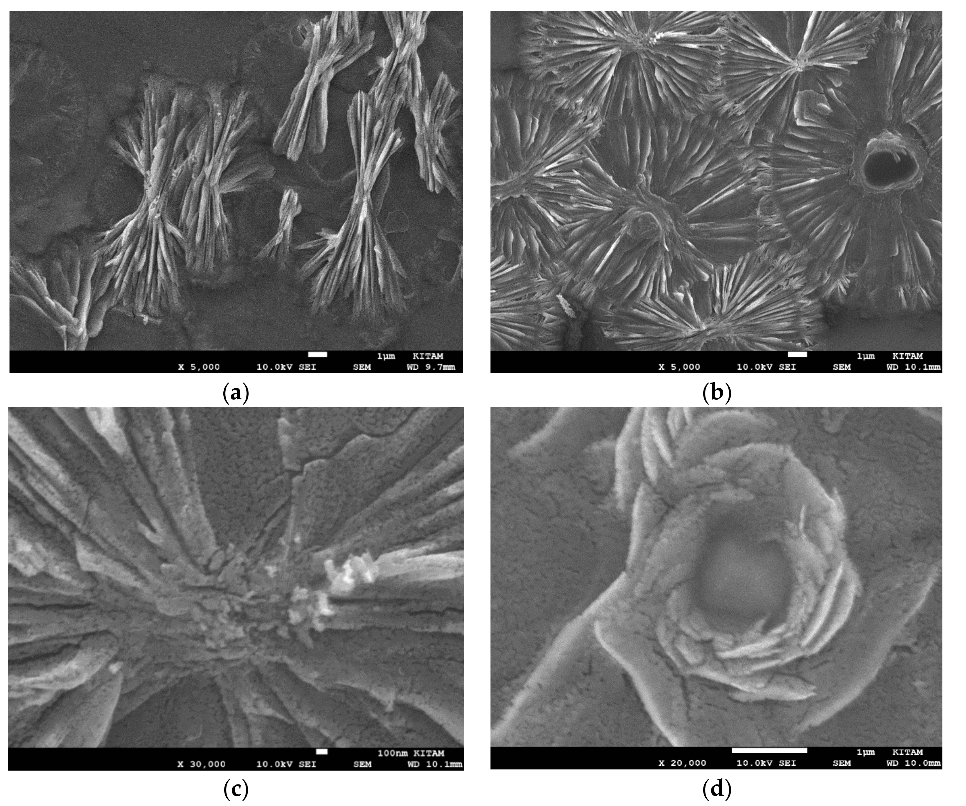
2.16.3. Microwave Processing of Silica Supported Manganese-Copper Binary Catalyst, Mn/Cu/Si = 1.5/0.5/1 with Plasma Generation

The objective of this study is to show that supported binary catalysts can create catalytic structures which are defect-rich (and hence have more accessible active sites) as well as offering the possibility of sequential catalysis because distinct catalyst domains are present in very close proximity. Such desirable catalyst structures appear to be formed through processing under a high energy environment and catalyst concentration. Therefore, we also investigate changes in the physical/chemical catalyst structure when fresh catalysts were subjected to further microwave irradiation with plasma generation. The second purpose here is to assess the long-term stability of these catalysts under service conditions.
Binary catalyst Mn/Cu/Si = 1.5/0.5/1 is obtained by irradiation of catalyst precursor (Mn and Cu nitrate salts) in silica support precursor fluid at 1800 W for 60 s. Following the evaporation of water and the decomposition of nitrate salts within ca. 40 s, generation of plasma was observed. Irradiation was stopped after a total processing time of 60 s.
The EDS images of the fresh catalyst at two magnifications are shown in Figure 34a,b at two magnifications and locations. Surface and the inner regions of the large catalyst particle show both chemical and morphological heterogeneity with Mn, Cu, Si and O-rich regions. It can be seen from the elemental analysis of the catalyst (Figure 34c–f) that both Si and O concentrations are low when Mn and Cu concentrations are high. The evaluation of the EDX-spectra obtained from four catalyst particles (including that shown in Figure 34a) at various locations is summarized in Table 13. Here the data are grouped into two; the regions with the highest Mn and with the highest Cu. The average composition of the total catalyst surface (such as shown in Figure 34a) is also tabulated in Table 13. It can be seen that, compared with Mn/Si = 2 catalyst (see Table 10) Mn concentration in the Mn-rich regions is significantly lowered by Cu in the binary catalyst. Nevertheless, due to the fact that Cu appears to phase separate out from SiO2 support, the surface of the Mn/Cu/Si = 1.5/0.5/1 catalyst is always Mn deficient and Mn/Cu molar ratio is smaller than the stoichiometric ratio of [Mn]/[Cu] = 3. The opposite is true for the ([Mn] + [Cu])/[Si] ratio, indicating that the walls of the pores are significantly richer in SiO2 compared with the expected stoichiometric ratio of 2/1. We also note that the mean oxygen concentration on the catalyst surface is lower compared with the Mn/Si = 2 catalyst, reflecting the presence of Cu in the catalyst. As seen from Figure 34b–f and Table 13, oxygen and Si concentrations are significantly low in Cu-rich regions.
When the freshly made Mn/Cu/Si = 1.5/0.5/1 catalyst is further subjected to microwave radiation with the generation of plasma, the main effect appears to be the enhancement of Mn concentration in the Mn-rich regions, reaching to the level of the corresponding Mn/Si = 2 catalyst as seen in Table 10 and Table 13.
Figure 34b,g,h illustrates the typical fine structure of the Mn/Cu/Si = 1.5/0.5/1 catalyst on the catalyst surface. Phase separated Mn-rich regions appear to form closely packed cuboidal capillaries as well as nano-plates of ca. 35 nm thickness as shown in Figure 34h. These plates when closely packed give the appearance of layered structures encountered in plasma treated BaTiO3.
Figure 35a–e illustrates the EDS layered image and elemental mapping of the Mn/Cu/Si = 1.5/0.5/1 catalyst after an extra 60 sec microwave irradiation with the generation of plasma. Here, a high concentration of Cu is localized but not dominant while Mn concentration is enhanced across the sample when compared with the corresponding mappings shown in Figure 34c–f.
Table 13 shows that Mn concentration doubles in the Mn-rich region while there is a slight reduction in Cu concentration in the Cu-rich domains upon further microwave irradiation. In all regions [Mn]/[Cu] molar ratio increases upon further irradiation, especially in the Mn-rich domains.
The physical structure of the fresh Mn/Cu/Si = 1.5/0.5/1 catalyst after a further 60 s microwave irradiation at 1800 W is illustrated in Figure 36a–f as a function of local composition.
Figure 36a,b shows the structure of the catalyst surface consists of ca. 0.2 μm particles with ca. 0.1 μm holes providing connections to the pores beneath them, the surface structure of which is illustrated in Figure 36c,d at two magnifications. Infact the dominant surface structure, shown in Figure 36a,b is similar to that of Mn/Si = 2 catalyst (Figure 28) but the surface decorations seen in Figure 28c,d are not present. In general, the surface structures inside the catalyst pores are substantially different than the catalyst surface as shown in Figure 28e,f and Figure 36e,f for Mn/Si = 2 and Mn/Cu/Si = 1.5/0.5/1 respectively. Note that the layered structures of the crystals covering the pore surface after an extra 60 s microwave irradiation (Figure 36f) are also present in Figure 29 and Figure 34.
The foregoing studies indicate that the presence of a second catalyst is useful in obtaining defective catalyst morphologies which increases the concentration of accessible high-activity sites. It can be seen from Table 10, Table 11, Table 12 and Table 13 that in the presence of Cu, catalyst oxygen concentration is some 20% lower due to the fact that Mn has higher oxidation states than Cu. Reduced lattice oxygen capacity is therefore a disadvantage when these catalysts are used for chemical looping reactions, for example, re-oxidation of the reduced catalyst using water to generate hydrogen.

2.17. Applications of Catalytic Microwave Induced Plasma

In the current process, following the decomposition of the catalyst precursor nitrate salt and the generation of plasma in air, the newly formed catalyst undergoes reduction which is however, not uniform across the catalyst. Reduction takes place on the catalyst surface, rather than within the walls of the pores due to the fact that plasma catalysis is a surface phenomenon, although plasma penetration and enhancement occur within the pores through interconnecting holes. The implications of these observations include porous catalyst design for plasma and chemical looping at a large scale.
Catalyst reduction takes place despite the presence of oxygen and the mechanism of the process can be described as:
N2 + 2x{O} → 2NOx + 2x{#} Oxidation of N2 by lattice oxygen of the catalyst oxide
2{#} + O2 → 2{O} Restoration of lattice oxygen by the re-oxidation of catalyst
where {O} represents the catalyst oxide lattice and {#} is the oxygen deficient lattice with oxygen vacancy #.
However, as these reactions take place in air and the products are NOx, oxygen is limited and hence the lattice oxygen restoration is not complete. Therefore, the concentration of reduced domains increases. The Equations (11) and (12) also represent a chemical looping reaction scheme involving N2 and the oxidized {O} or the reduced {#} catalyst. Here, the nitrogen and oxygen activations are through plasma which is promoted by the catalyst itself. The above chemical looping reaction scheme for nitrogen fixation takes place in microscopic scale and hence it can be scaled-up and applied to various important chemical processes as discussed below in which the oxidation of the reduced catalyst {#} can be carried out by CO2 or H2O in order to generate CO or H2 respectively.

2.17.1. Carbon Dioxide and Flue Gas Conversion to Ammonia and Fertilizers

This type of chemical looping reaction scheme can be applied to an important reaction involving a mixture of CO2 and N2 which is of course encountered in combustion gases. Catalytic plasma CO2 conversion to CO has been studied extensively [3,19,20,21,22,103,104,105,106,107,108,109,110], including the effects of nitrogen [108,109] and water [110] on CO2 conversion. In particular, the effect of dilution of CO2 with N2 has been shown to enhance CO2 conversion which is accompanied by the evolution of NOx (NO, NO2) as well as N2O [3,108,109]. It is shown that in a nonthermal annular dielectric barrier discharge reactor packed with 3 mm BaTiO3 catalyst, CO2 conversion to CO increases from 19% (pure CO2) to 35% when CO2 is added 80% N2 at a specific input energy (SIE) of 36 kJ/L [109]. CO2 reduction is accompanied by the production of NOx reaching maximum at 50% N2 at a concentration level of ca. 3100 ppm at 36 kJ/L [109].
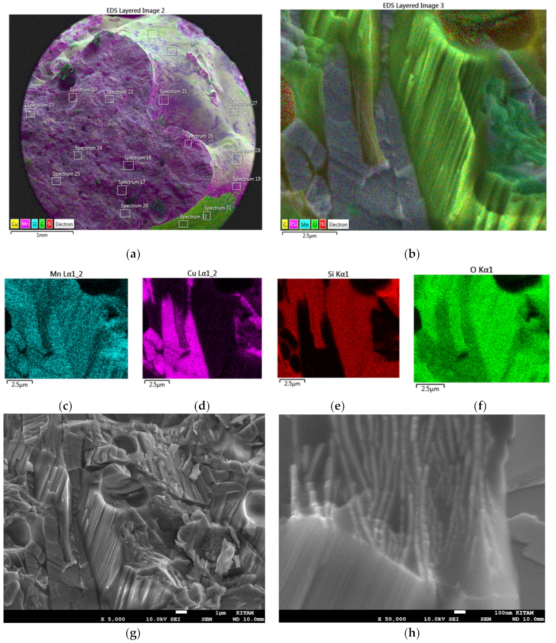
The mechanism of CO2 reduction and N2 oxidation in plasma without BaTiO3 has been discussed in detail [108]. In the presence of BaTiO3 in which the lattice oxygen is denoted by {O}, the simplified mechanism for CO2 reduction and N2 oxidation can be written as:
N2 + 2{O} → 2NO + 2{#} N2 oxidation and catalyst reduction
CO2 + {#} → CO + {O} CO2 reduction and catalyst re-oxidation
2NO + {#} → N2O + {O} Consumption of adsorbed NO for N2O production and catalyst re-oxidation
NO + {O} → NO2 + {#} Consumption of adsorbed NO for N2O production and catalyst re-oxidation
This mechanism does not exclude CO2 reduction and N2 oxidation in the plasma space as proposed in [108] but it represents the contribution of BaTiO3 to CO2 and N2 conversions. The catalyst contribution appears to be highly significant as the conversion in the presence of BaTiO3 at the same specific input energy is three times greater for NO generation compared with no BaTiO3 [108,109]. The understanding of the mechanism of catalytic plasma reactions as regards the contributions of each reaction domain, is therefore very important in reducing the energy cost of catalytic plasma reactions [111].
It is unlikely that at these levels of conversions and energy costs, mixed CO2 and N2 could be exploited commercially. Nevertheless, the understanding of the reaction mechanism with catalysts, catalyst and process design, CO2 + N2 conversion to CO, NO and NO2 can lead to the manufacture of several chemicals including ammonia and urea through the reactions [2,3,112,113]:
CO 2   + ½   N 2     NO + CO   + 3 / 2 H 2   NH 3   + CO 2     Ammonium   carbamate     urea
There are several advantages of urea as a fertilizer, including the fact that it can lead to CO2 sequestration through CaCO3 formation. However, the above process would require extensive cleaning of flue gases and separation processing as well as hydrogen production from renewable sources such as biomass gasification, water electrolysis, solar water splitting or indeed through this current process.

2.17.2. Production of Nitric Acid, Hydrogen, Ammonia and Ammonia Derivatives from Air and Water

Integrated processes have inherent economic benefits. As the world’s largest chemical, NH3 is seen as the most important target for nitrogen fixation. The demand for ammonia as a renewable energy vector and hydrogen source is likely to continue to grow. However, currently, some 85% of ammonia is consumed in agriculture as fertilizer, in which ammonium nitrate is the prime soil input. Therefore, direct fixation of nitrogen through ammonia into fertilizers (chemical fixation) and into ammonium carbamate as reversible fixation has been shown to significantly reduce the energy cost of ammonia [2,3].
Another important potential nitrogen fixation is in nitric acid (for nitrate fertilizers) which is currently obtained from the oxidation of ammonia itself. Therefore, the current methods of ammonia and nitric acid productions are not sustainable, thus alternative sustainable carbon-free methods have been investigated [11,112,113,114,115,116,117]. Here, we present an alternative route for nitrogen fixation for nitric acid and hydrogen production by chemical looping using the plasma generating catalyst systems described in the foregoing sections. In this method catalysts, based on spinel, perovskite or a mixture of both (such as composite catalysts {M/Si = X}/BT = F) or binary catalysts are used for nitrogen fixation from air to obtain NO and NO2 followed by the re-oxidation of the catalyst with water to obtain hydrogen for use in ammonia production. In this process. N2O formation is reduced through the use of spinel or perovskite catalysts (mainly cobalt based) or by the optimization of processing conditions [112,113,114,115].
Figure 37 diagrammatically illustrates the proposed integrated process for chemical nitrogen fixation from air for nitric acid production and hydrogen generation from water using the current plasma generating chemical looping catalysts for ammonia production [94].
In Figure 37, air separation takes place in Reactor-1 to obtain oxygen and nitrogen enriched streams. Oxygen is used for NO oxidation in Reactor-4 to obtain nitric acid while a nitrogen enriched stream is fed into the plasma reactor, Reactor-2A for NO production. The oxygen content is controlled by the injection of air into Reactor-2A so as to prevent N2O formation. The oxide catalyst represented as MaOb is also fed into Reactor-2A and reduced catalyst MaOb-c is regenerated in the Reactor-2B using water. The resulting hydrogen and nitrogen from Reactor-1 are fed into the catalytic ammonia reactor (Reactor 3A) [2] and the catalyst MaOb is recycled back to Reactor-2A. The relevant simplified chemical reactions are:
MaOb + c/2 N2 = Ma Ob−c + c NO Reactor-2A
Ma Ob−c + c H2O = MaOb + c H2 Reactor-2B
Reactor-6 separates nitric acid and the unreacted gases (N2 + O2) which are recycled back to Reactor-2A. In order to enhance NH3 conversion and lower the energy cost of NH3 production, nitric acid (or indeed other acids) are mixed with an acid carrier or soil additives such as hydrophilic micro-porous polymers known as PolyHIPE Polymers (PHP) [2,3,4]. Reactor-5 is used for the mixing of the soil additives/acid carrier with nitric acid (or other acids such as sulphuric or phosphoric acids). Acid absorbed by the carriers is neutralized by NH3 (produced in Reactor-3A) in Reactor-3B thus forming a fertilizer as described previously [2,3,4]. The Reactor-3 is a multi-reaction zone plasma reactor [2,3] used in order to shift the reaction equilibrium towards NH3 formation at the NH3 reaction zone.
Mn, Co and Fe represent the best chemical looping oxide catalysts as the re-oxidation temperature for them is low and well below their melting temperatures [45,46,118,119]. Here, M/Si = X (X ≥ 1) has been used for several purposes. They include, plasma generation under microwave irradiation, as plasma catalyst and as the chemical looping agent for hydrogen generation.

3. Experimental

3.1. Materials and Catalyst Synthesis

Barium titanate (BaTiO3) perovskite was obtained from Catal Ltd. (Sheffield, UK) with permittivity value 1000–6000. The catalyst and co-catalyst precursors used in this study were nitrate hydrates represented by M(NO3)x. yH2O where M = Cr, Mn, Fe, Co, Ni, Cu (Transition metals) while the catalyst promoters include, M = Mg, Al, Ca, Zn, Sr, Ba, La, Bi. Precursor nitrates were supplied by Sigma Aldrich and used as received. The catalyst support precursor was an epoxy silane (γ-Glycidoxypropyltrimethoxysilane) coated silica particle (size 7 nm) dispersion supplied by Nouryon, (formerly AkzoNobel), Bohus, Sweden in the form of a 30 wt% dispersion under the trade name of Levasil CC301 (formerly Bindzil CC301).
Catalyst preparation was carried out using a Panasonic NE 1853 commercial microwave oven (Panasonic Corporation, Osaka, Japan) with a stepwise variable power ranging from 340 W to 1800 W in ten steps. Analysis of nitric oxide in air was carried out using an Agilent 490 Micro-GC Gas Analyzer [1] (Agilent Technologies, Stockport, UK).

3.2. Plasma Generation and Nitric Oxide Production During the Microwave Irradiation of Barium Titanate Particles in Air

Plasma generation in air was carried out using 100 g spherical BaTiO3 particles (3 mm diameter) in a microwave reactor produced by Milestone S.R.I. (Sorisole, Italy) [2,14]. BaTiO3 particles were placed in a 200 mL conical flask with air inlet and gas outlet. Outlet gases were fed into an on-line nitric oxide analyzer (Agilent 490 Micro-GC Gas Analyzer) as described previously [1] with a full range of 500 ppm. Plasma generation could be visually observed via a camera fitted to the reactor. Either continuous or programmed (10 sec on followed by 20 sec off) microwave power was applied. Temperature of the barium titanate was also recorded on-line.

3.3. Catalyst Characterisation

The X-ray Diffraction (XRD) studies were carried out using a Smartlab model Rigaku (Tokyo, Japan) equipment with facility to provide crystallize size based on the Scherrer equation [71]. BET surface area measurements were carried out using a Beckman-Coulter SA 3100 Analyzer. The scanning electron microscope used in the present work was JSM-777001F model Joel (Tokyo, Japan) equipment with Energy Dispersive X-ray Spectroscopy (EDS) analysis. Metal catalysts were not coated, but BaTiO2 samples were coated with gold (for images at high magnifications) and with carbon when EDS analysis was used.

3.4. Supported Catalyst Preparation

Silica supported catalysts were prepared by using the method described previously [1,2]. Since the catalyst precursor and catalyst support (SiO2) precursor are co-assembled from a solution followed by catalyst precursor decomposition, we use molar composition in describing them. In terms of notation used previously [1,2], the catalyst system is denoted as M/Si = X in which the metal catalyst (M) is supported on SiO2 with molar ratio of X (X = 1/9; 1/5; 1/4; 1/3; 1/2; 1/1; 2/1 in this study).
A predetermined amount of catalyst precursor represented by M(NO3)x. yH2O was dissolved in the silica support catalyst fluid (Levasil CC301) to obtain a desired M/Si molar ratio. 10 mL of this stock fluid is placed in a ceramic bowl of 100 mL capacity. This fluid is then microwaved at various microwave power ratings. In all cases, upon microwave irradiation, a highly porous Catalyst precursor/Silica structure is obtained when water is lost from the mixture. Immediately afterwards, the catalyst precursor starts decomposing with the evolution of NOx [1]. After the completion of gas evolution, the silica supported catalyst oxide is recovered. The whole processes take ca. 1–4 min depending on the power and catalyst concentration. In our previous studies, it was found that, subject to the type of catalyst (either binary or single) and catalyst loading, there appeared to be a critical power required in order to initiate the catalyst nitrate decomposition. Prolonged microwave irradiation does not initiate the catalyst nitrate decomposition. In these experiments, we determine the critical microwave power P*, as a function of catalyst concentration. The catalyst yield is also determined at the end of each experiment.

3.5. Supported Binary and Composite Catalysts

It is well known that the catalysts operating under nonthermal plasma do not suffer catalyst deactivation due to, for example, carbon deposition [68]. It is also known that plasma generation is most effective across a bed of high permittivity materials such as BaTiO3 and that a mixture of catalyst and BaTiO3 can result in higher yield compared with either of the components [14,16]. Here, we prepared supported binary and composite catalysts. Binary catalysts are represented by M(1)/M(2)/Si = X/Y/Z where X, Y, Z are the molar concentrations of catalysts M(1) and M(2) and the support SiO2 respectively. In the present studies, M(1) = Mn or Co and M(2) = Cu.
In the case of “Composite” catalysts, BaTiO3 particles were dispersed in the M/Si = X catalyst precursor fluid and subjected to microwave irradiation. As it is necessary to form a fluid film during the water evaporation stage of the synthesis, we used BaTiO3 particles with size range 10–53 μm (average size D50 = 32 μm) so that these particles do not disrupt film formation and can be observed in the resulting catalyst. These BaTiO3 containing samples are coded as {M/Si = 2}/BaTiO3= F where F is the catalyst/BaTiO3 molar ratio; i.e., F = [M]/[Ba]. In total, 10 mL catalyst and silica support precursor fluid was added sufficient amount of fresh BaTiO3 powder (crushed from 3 mm particles) so as to obtain nominal catalyst/BaTiO3 molar ratio of 1/4; i.e., [M]/[Ba] = 1/4.

4. Conclusions

The combination of classical catalysts with direct nonthermal stimuli, which direct energy into the reaction coordinate of targeted elementary steps without significantly affecting possible other reactions, should result in the lowering of energy costs of nitrogen fixation and hydrogen generation [120]. The current findings also make it possible to design both novel catalyst and plasma reactors with or without electrodes and high electric potential. Plasma is highly effective to maintain high catalyst activity which increases with the promotion of terrace sites at the expense of step sites [30,97,98,99]. It has been suggested that the concentration of such sites can be increased by high voltage pulsed discharges [17,121] as well as by microwave [20] or gliding arc discharges [21]. Clearly, the current type of catalyst encompasses all of these means of achieving high catalyst activity through the generation of accessible high surface area with topological and chemical heterogeneity.
In the current catalyst processing, microwave radiation results in thermal shock which generates very high temperature gradients causing particle disintegration due to high internal stresses. Particle disintegration applies both to BaTiO3 and the coated silica particles. In proposing a tentative mechanism for the catalyst synthesis through the current method of co-assembly of the support and catalyst, it was shown that the agglomerated and coated silica particles (ca. 7 nm) disintegrate and form lamellar assemblies after the decay of thermal and mechanical shocks [1]. Particle disintegration under thermo-mechanical stress also applies to the delamination of BaTiO3 and it explains why despite extensive SEM and EDS imaging studies, large BaTiO3 particles (ca. 10–50 μm) in the catalyst were not observed, despite very high BaTiO3 concentration.
A tentative mechanism of co-assembled supported catalyst structure formation is shown in Figure 38. Following the disintegration of the catalyst support resulting from thermo-mechanical stress and plasma-shock, a self-assembly of the support particle takes place [1] which can absorb any further microwave induced shocks. Energy dissipation occurs through the rapid evaporation of water from the lamellar bilayers which essentially immobilizes the support/catalyst assemblies. During water evaporation, leakage of metal ions from the support layers takes place and this may be promoted in binary catalysts resulting in phase separation. These stabilized structures agglomerate to form large ribbon-like higher order structures (as depicted in Figure 38) followed by further agglomeration into porous catalysts with hierarchic pores. In the presence of support/catalyst or catalyst/co-catalyst phase separations, surface decorations occur as illustrated in Figure 38. It is likely that plasma generation occurs within the pores created by the lamellar structures consisting of a dielectric barrier (silica) and a conductor (catalyst).
The presence of BaTiO3 in composite supported catalysts can enhance electrical activity in these structures. As shown in Figure 15, BaTiO3 particles delaminate/exfoliate (Figure 15d,e,f) followed by fragmentation into nano-plates (Figure 15g,h,i). They can therefore act as the catalyst support with silica.

4.1. Microwave Induced Plasma Generation in Supported Single Catalyst Spinel Oxides and Perovskite-Type Plasma Catalysts

The processing and characterization of the novel supported catalyst system described previously [1] and symbolized as M/Si = X has been extended to cover a concentration range when the molar ratio of the catalyst (M) and support (Si) is 0.1 < X < 2. These catalyst systems are processed from a fluid state containing the catalyst precursor salt and coated silica support which is subjected to microwave irradiation in air in such a way that the film formation is promoted; without the confinement of the growing film [1]. Following the evaporation of water, a highly porous lamellar catalyst salt and silica material is obtained which immediately undergoes decomposition with the evolution of NO and NO2. It is found that the critical microwave power (P*) necessary for the salt decomposition increases with increasing catalyst concentration (i.e., X) and in general P* increases with atomic number for the transition catalysts (Cr, Mn, Fe, Co, Ni, Cu, investigated). In alkaline earth metals (Mg, Ca, Sr, Ba investigated) or post transition metals (Al, Zn, Bi investigated) or Lanthanum, P* is approximately constant. However, it was found that, for Cr, Mn and Fe, P* remains low and constant but for Co, after increasing with increasing catalyst concentration, X, P* starts decreasing when X ≥ 1 which is also accompanied by plasma discharge immediately after the decomposition of the catalyst precursor salt. Plasma generation during microwave processing also takes place for the other spinel type oxide forming catalysts in which Mn has been investigated in detail. It was also found that BaTiO3 perovskite also emits plasma during microwave irradiation.

4.2. Characteristics of Single Supported Catalysts and BaTiO3

After synthesis, the analysis of these catalysts included BET surface area, XRD, SEM and EDS. XRD analysis only yielded limited results for any insight into the chemical and morphological changes in M/Si = X for Co and Mn when X = 1 or 2 as well as for BaTiO3. However, SEM and EDS studies indicated that for all of the catalysts which emitted plasma in air, the catalyst structure was highly inhomogeneous with microscopic scale reduced and oxidized domains within micrometer proximity to each other. The chemical composition in these domains were reflected in morphological changes. Typically, these high surface area porous catalysts have ca. 1 μm thick nano-porous walls. Morphological changes occurred on the surfaces penetrating into the pore walls. Two heterogeneity indices were defined with respect to [M]/[Si] and [O]/{[M] + [Si]} ratios. Heterogeneity indices were evaluated as a function of catalyst concentration and it was shown that it increased rapidly when plasma generation took place (X ≥ 1). It was found that in some regions, the phase separated catalyst was almost completely reduced to metal, M0.
In the case of BaTiO3 solid spherical particles (ca. 3 mm diameter), microwave irradiation and plasma generation resulted in drastic morphological changes on the surface and within the particles, including electrical treeing due to intense electrical activity and pore formation. It was found that nitrogen was attached to BaTiO3 structure and in nitrogen rich regions, oxygen concentration was also high (70 mol%), above the full lattice oxygen level of 60 mol%. In regions with no nitrogen, lattice oxygen levels were as low as 30 mol%. Plasma generation during microwave irradiation with BaTiO3 also resulted in NOx evolution.
These results indicate that during microwave irradiation and plasma generation in air, nitrogen extracts lattice oxygen from the catalyst to form NOx which are also generated in the plasma space in the presence of oxygen. It is likely that some of the extracted oxygen is replaced from air in the perovskite or spinel catalyst oxides. However, as the oxygen concentration is limited, some of the reduced catalyst domains are not re-oxidized as evaluated by EDS and supported by morphological changes observed by SEM. The morphological changes, within the catalyst reflect the chemical changes.

4.3. Mixed Spinel Oxide and Perovskite Catalysts

We have recently shown that the combination of BaTiO3 and silica supported catalyst, Ni/Si = 1/4, increased nitrogen conversion in catalytic non-thermal plasma synthesis of NH3 in a packed bed plasma reactor [14,16] as well as in CO2 reduction CO [107]. This was attributed to maintenance of plasma across the reactor and near the catalyst sites by BaTiO3. The current findings support this conclusion as we have seen that plasma activity was observed within BaTiO3 pores. It is therefore possible to design new catalyst systems where BaTiO3 (or other high permittivity materials) can be dispersed into the M/Si = X catalyst [3].
The BaTiO3 particle shown in Figure 31a has a size of ca. 500 μm. It was generated through the fragmentation of the initial 1 mm spherical BaTiO3 particle. However, if the size of BaTiO3 particles in the support/precursor feed solution were small (i.e., 10–53 μm used in the experiments), these particles appeared to fragment into a size which could not be identified at the magnifications employed in this study. Therefore, in some cases, large particles were deliberately included in the precursor fluid to observe them after catalyst formation. It is somewhat surprising that such drastic fragmentation/fracture takes place in a very short time. It is therefore possible that the stresses necessary to achieve this process are very large and develop very fast. Similar to the fracture processes encountered in liquid-liquid or solid-liquid systems or mechano-chemical reactions, this process can be described through the generalization of the fracture criterion used in these systems [121,122,123]. Here, the scaling is carried out using stress power (Energy per unit time imposed on a particle), rather than stress (which is a tensorial quantity and hence not invariant) or energy. Stress power has to exceed the cohesive energy density which can be further modified to take into account the non-equilibrium dynamics of the fracture process, including the uneven distribution of stress and stress concentrations due to very high temperature gradients. The phenomenon of Flow Induced Phase Inversion, (FIPI), (as well as other flow induced associated phenomenon associated with macromolecules or particulate systems) has been utilized in process intensification in particle technology and described in terms of stress power [122,124,125,126]. This criterion for the fragmentation [121,122,123] of the dielectric particles under superimposed microwave radiation and deformation can be generalized as;
FN = PS/(a CED/λ) > 1
where FN is the ratio of the input surface power density, PS, and dynamic surface cohesive energy density, (a CED/λ) both of which represent energy input per unit time, per unit area. Here, a = particle size, CED is the cohesive energy density and λ is the relaxation time. In the case of liquid fracture (i.e, droplet formation/emulsification) [122,123], λ is inversely proportional to viscosity and can be obtained from the proton-relaxation NMR (i.e., λ = T2-relaxation time) [123]. λ decreases exponentially with increasing viscosity. Equation (20) can be considered to be the equivalent of Capillary Number [123,124,126] used in droplet breakup in liquid-liquid systems. Equation (20) predicts that the required power for fragmentation decreases with decreasing particle size as observed in the present study.

4.4. Binary Supported Catalysts

In order to demonstrate the types of structures which can be obtained for different catalytic reactions, we used copper as the co-catalyst. As shown previously, Cu/Si = X (X > 1) catalyst could not be synthesized by microwave even at the highest available power of 1800 W. Here we synthesized two different Cu catalysts; namely Co/Cu/Si = 1/1/8 and Mn/Cu/Si = 1.5/0.5/1. It was found that in Co/Cu/Si = 1/1/8 catalyst system, after the evaporation of water (and the formation of the porous catalyst/support precursor salt), nitrate decomposition did not generate microwave generation. In the case of Mn/Cu/Si = 1.5/0.5/1, decomposition of the nitrate catalyst was achieved with microwave radiation followed by plasma generation.
Nevertheless, the resulting structures are fundamentally similar except for the extent of heterogeneity. Co and Cu as well as Mn and Cu were partially phase separated forming Co/Cu and Mn/Cu rich phases. Copper rich phases were identified as flower-like decorations grown from nano-particles present on the silica rich pore surfaces while Co and Mn rich phases consisted of metal/metal oxide crystals.

4.5. Application to Nitrogen Fixation from Air and Hydrogen Generation from Water by Chemical Looping

It is shown that the multi-catalytic domain catalysts act as chemical looping reactors. It is therefore proposed that NO and NO2 evolution during microwave plasma generation with spinel oxides and perovskites, can be used to produce nitric acid. Hydrogen generation by steam re-oxidation of the reduced catalyst can be achieved through a chemical looping water splitting process. A fully integrated process is described diagrammatically in Figure 37 and detailed in [94].

4.6. Recent Advances in Plasma Catalysis and Catalysts for Plasma Reactions

Recently, with the help of modelling, important advances have been made in the understanding of plasma catalysis and catalysts for plasma reactions to achieve synergy between various elements of the catalytic plasma reactors [17,20,22,127,128,129,130,131,132,133,134,135]. These developments have been critically analyzed by Whitehead [136,137]. The available data indicate that the porous catalysts can provide synergy in catalytic plasma reactions through plasma generation within pores especially when the pore entrance is restricted [125,126,127,128] and that the surface irregularities on the catalyst or points of contact formed between the catalytic particles can cause enhanced electric fields when exposed to the plasma [125,126,127,128,129]. These can give rise to local hotspots where a disproportionally high amount of the plasma-catalytic processing may take place [130,135,137]. The effect of high dielectric constant materials, including BaTiO3 and SiO2 on the enhancement of catalytic activity is known [127,137].
The experimental evidence provided in the current study does verify these predictions and observations and justifies the synthesis of porous catalysts with a hierarchic pore structure covering a pore-size and connectivity range from nanometer-to-submillimeter. The processing under non-equilibrium thermodynamic conditions through high density power shock with plasma generation, not only provides very rapid processing but also a catalyst with a very high degree of morphological and chemical heterogeneity. In turn, this structural heterogeneity provides enhancement and the accessibility of high activity catalytic sites as demonstrated in [95,96,97,98,99] even in reactions without plasma. Such catalytic sites in the presence of plasma enhance the synergy between the catalyst and plasma. Porous catalysts are also needed when they are used in chemical looping processes; when the re-oxidation of the reduced/oxygen depleted catalyst with water or CO2 is needed.

4.7. Applications in Electromagnetic Radiation Protection and Catalytic Radar Absorption Materials

Electromagnetic radiation absorbing materials are important due to the advances made in communication and detection technologies such as military aircraft, ships, vehicles, environmental protection and telecommunication equipment. In particular, microwave absorption materials are particularly relevant in radar detection avoidance and stealth. Within microwave radiation, the frequency range of 2–18 GHz is highly relevant for radar applications. Radiation absorption and energy dissipation in the form of heat by a material occur via dielectric and/or magnetic loss [138,139,140,141,142]. Therefore, so called “Radar Absorbing Materials” (RAMs) should have large permittivity and permeability for an efficient absorber [143,144,145].
The application of the current plasma generating single or mixed supported or composite catalysts should satisfy this criterion because high permittivity and permeability domains co-exist within the catalyst as a highly reactive state due to their high porosity, surface area and reactivity. Furthermore, plasma itself is used as a reactive radar absorption medium [138] although this method is not suitable in most applications. On the other hand, as in the present case, when plasma is generated upon microwave excitation of the supported catalysts, they can act as catalytic radar absorbing materials (C-RAMs) over a broad frequency range [146].

Funding

This research was funded by two European Union grants acronymed COPIRIDE, (Grant No: CP-IP 228853) and POLYCAT (Grant No: CP-IP 246095) which were received and directed by the author at Newcastle University, UK, and it was further extended by another European Union grant administered by the Turkish Scientific Technical Research Council, TUBITAK (Grant Scheme: BIDEB 2236, Grant No: 115C045) at Ondokuz Mayis University, Samsun, Turkey.

Acknowledgments

This research was completed at Case Western Reserve University, Cleveland, Ohio, USA where the author was a visiting professor. The author is grateful for the above cited grants and expresses his thanks to the technical support staff at Ondokuz Mayis University’s central research and development laboratories (KITAM); in particular to Yunis Gedik, Nalan Karakullukcu, Filiz Ozturk, Gediz Uguz, Aysun K. Yalcin for their help in the use of SEM/EDS, XRD, BET, FTIR facilities. The author thanks Mehmet Kuran (Vice-president of Ondokuz Mayis University) and Mohan Sankaran (Case Western Reserve University) for their support, Peter Greenwood (Nouryon) for providing several grades of Levasil colloidal silica dispersions, Max Hadfield and Duncan Rove (Analytix Ltd, Newcastle upon Tyne, UK) for the use of some of their facilities.

Conflicts of Interest

Two British Patent Applications, partially based on this research, have been made recently.

References

  1. Akay, G. Co-Assembled supported catalysts: Synthesis of nano-Structured supported catalysts with hierarchic pores through combined flow and radiation induced co-assembled nano-reactors. Catalysts 2016, 6, 80. [Google Scholar] [CrossRef] [Green Version]
  2. Akay, G. Sustainable ammonia and advanced symbiotic fertilizer production using catalytic Multi-Reaction-Zone Reactors with nonthermal plasma and simultaneous reactive separation. ACS Sustain. Chem. Eng. 2017, 5, 11588–11606. [Google Scholar] [CrossRef]
  3. Akay, G. A novel Catalytic Multi-Reaction Zone Reactor System. PCT Patent WO 2018/182551, 28 September 2017. [Google Scholar]
  4. Nakamura, T. Hydrogen production from water utilising solar heat at high temperatures. Sol. Energy 1977, 19, 467–475. [Google Scholar] [CrossRef]
  5. Kodama, T.; Nakamuro, Y.; Mizuno, T. A two-Step thermochemical water splitting by iron-Oxide on stabilized zirconia. J. Sol. Energy Eng.-Trans. ASME 2016, 128, 3–7. [Google Scholar] [CrossRef]
  6. Kodama, T.; Gokon, N. Thermochemical cycles for high temperature solar hydrogen production. Chem. Rev. 2007, 107, 4048–4077. [Google Scholar] [CrossRef]
  7. Allendorf, M.D.; Diver, R.B.; Siegel, N.P.; Miller, J.E. Two-Step water splitting using mixed-Metal ferrites: Thermodynamic analysis and characterisation of synthesized materials. Energy Fuels 2008, 22, 3115–4124. [Google Scholar] [CrossRef]
  8. Abanades, S.; Charvin, P.; Flamant, G.; Neveu, P. Screening of water splitting thermochemical cycles potentially attractive for hydrogen production by concentrated solar energy. Energy 2006, 31, 2805–2822. [Google Scholar] [CrossRef]
  9. Kaneko, H.; Hasegawa, T.; Mori, K. A-Site substitution effect of perovskite-Type cobalt and manganese oxides on two-Step water splitting reactions for solar hydrogen production. AIP Conf. Proc. 2017, 1850, 100011. [Google Scholar]
  10. Yang, Q.; Hu, H.; Chen, W.; Xu, J.; Zhang, J.; Wu, S. The main plasma chemical process of nitric oxide production by arc discharge. Plasma Sci. Techol. 2011, 13, 702–707. [Google Scholar] [CrossRef]
  11. Bian, W.; Song, X.; Shi, J.; Yin, X. Nitrogen fixed into HNO3 by pulsed high voltage discharge. J. Electrost. 2012, 70, 317–326. [Google Scholar] [CrossRef]
  12. Patil, B.S.; Wang, Q.; Hessel, V.; Lang, J. Plasma N2-Fixation: 1900–2014. Catal. Today 2015, 256, 49–66. [Google Scholar] [CrossRef]
  13. Cherkasov, N.; Ibhadon, A.O.; Fitzpatrick, P. A review of the existing and alternative methods for greener nitrogen fixation. Chem. Eng. Process. Process Intensif. 2015, 90, 24–33. [Google Scholar] [CrossRef]
  14. Akay, G. Ammonia Production by Integrated Intensified Processes. U.S. Patent 9416019, 16 August 2016. [Google Scholar]
  15. Patil, B.S.; Cherkasov, N.; Lang, J.; Ibhadon, A.O.; Hessel, V.; Wang, Q. Low temperature plasma-Catalytic NOx synthesis in a packed DBD reactor: Effect of support materials and supported active metal oxides. Appl. Catal. B Environ. 2016, 194, 123–133. [Google Scholar] [CrossRef] [Green Version]
  16. Akay, G.; Zhang, K. Process Intensification in Ammonia Synthesis Using Novel Coassembled Supported Microporous Catalysts Promoted by Nonthermal Plasma. Ind. Eng. Chem. Res. 2017, 56, 457–468. [Google Scholar] [CrossRef] [Green Version]
  17. Kim, H.H.; Teramoto, Y.; Ogata, A.; Takagi, H.; Nanba, T. Plasma catalysis for environmental treatment and energy applications. Plasma Chem. Plasma Process. 2016, 36, 45–72. [Google Scholar] [CrossRef]
  18. Iwamoto, M.; Akiyama, M.; Aihara, K.; Deguchi, T. Ammonia synthesis on wool-Like Au, Pt, Pd, Ag, or Cu electrode catalysts in nonthermal atmospheric-Pressure plasma of N2 and H2. ACS Catal. 2017, 7, 6924–6929. [Google Scholar] [CrossRef]
  19. Patil, B.S.; Hessel, V.; Seefeldt, L.; Dean, D.R.; Hoffman, B.M.; Cook, B.J.; Murray, L.J. Nitrogen fixation. In Ullmann’s Encyclopedia of Industrial Chemistry; Wiley-VCH Verlag GmbH: Weinheim, Germany, 2017. [Google Scholar]
  20. Snoeckx, R.; Bogaerts, A. plasma technology. Chem. Soc. Rev. 2017, 46, 5805–5863. [Google Scholar] [CrossRef] [Green Version]
  21. Wang, W.; Patil, B.; Heijkers, S.; Hessel, V.; Bogaerts, A. Nitrogen fixation by gliding arc plasma: Better insight by chemical kinetics modelling. ChemSusChem 2017, 10, 2145–2157. [Google Scholar] [CrossRef] [Green Version]
  22. Bogaerts, A.; Neyts, E.C. Plasma technology: An emerging technology for energy storage. ACS Energy Lett. 2018, 3, 1013–1027. [Google Scholar] [CrossRef] [Green Version]
  23. Peng, P.; Cheng, Y.; Hatzenbeller, R.; Addy, M.; Zhou, N.; Schiappacasse, C.; Chen, D.; Anderson, E.; Liu, Y.; Chen, P.; et al. Ru-Based multifunctional mesoporous catalysts for low pressure and non-Thermal plasma synthesis of ammonia. Int. J. Hydrogen Energy 2017, 42, 19056–19066. [Google Scholar] [CrossRef]
  24. Patil, B.S.; Peeters, F.J.J.; van Rooij, G.J.; Medrano, J.A.; Gallucci, F.; Lang, J.; Wang, Q.; Hessel, V. Plasma assisted nitrogen oxide production from air: Using pulsed powered gliding arch reactor for a containerized plant. AIChE J. 2018, 64, 526537. [Google Scholar] [CrossRef] [Green Version]
  25. Shah, J.; Wang, W.; Bogaerts, A.; Carreon, M.L. Ammonia synthesis by radio frequency plasma catalysis: Revealing the underlying mechanisms. ACS Appl. Energy Mater. 2018, 1, 4824–4839. [Google Scholar] [CrossRef]
  26. Peng, P.; Chen, P.; Schiappacasse, C.; Zhou, N.; Anderson, E.; Chen, D.; Liu, J.; Cheng, Y.; Hatzenbeller, R.; Addy, M.; et al. A review on the non-Thermal plasma-Assisted ammonia synthesis thechnologies. J. Clean. Prod. 2018, 177, 597–609. [Google Scholar] [CrossRef]
  27. Hong, J.; Prawer, S.; Murphy, A.B. Plasma catalysis as an alternative route for ammonia production: Status, mechanism and prospects for progress. ACS Sustain. Chem. Eng. 2018, 6, 15–31. [Google Scholar] [CrossRef]
  28. Chen, J.G.; Crooks, R.M.; Seefeldt, L.C.; Bren, K.L.; Bullock, R.M.; Darensbourg, M.Y.; Holland, P.L.; Hoffman, B.; Janik, M.J.; Jones, A.K.; et al. Beyond fossil fuel-Driven nitrogen transformations. Science 2018, 360. [Google Scholar] [CrossRef] [Green Version]
  29. Li, S.; Medrano, J.A.; Hessel, V.; Gallucci, F. Recent progress of plasma-assisted nitrogen fixation research: A review. Process 2018, 6, 248. [Google Scholar] [CrossRef] [Green Version]
  30. Mehta, P.; Barboun, P.; Herrera, F.A.; Kim, J.; Rumbach, P.; Go, D.B.; Hicks, J.C.; Schneider, W.F. Overcoming ammonia synthesis scaling relations with plasma-Enabled catalysis. Nature Catal. 2018, 1, 269–275. [Google Scholar] [CrossRef]
  31. Shah, J.; Wu, T.; Lucero, J.; Carreon, M.A.; Carreon, M.L. Nonthermal plasma synthesis of ammonia over Ni-MOF-74. ACS Sustain. Chem. Eng. 2019, 7, 377–383. [Google Scholar] [CrossRef]
  32. Akay, G.; Burke, D.R. AgroProcess intensification through synthetic rhizosphere media for nitrogen fixation and yield enhancement. Am. J. Agric. Biol. Sci. 2012, 7, 150–172. [Google Scholar]
  33. Akay, G.; Fleming, S. AgroProcess Intensification: Microbioreactors as soil additives with nitrogen fixing bacterium Azospirillum brasilense to enhance its potential as self-Sustaining biofertiliser. Green Process. Synth. 2012, 1, 427–437. [Google Scholar]
  34. Akay, G.; Burke, D.R. Synthetic Symbiotic System as Soil Additives to Deliver Active Ingredients through Plant Roots for Enhanced Plant and Crop Yield. U.S. Patent 8898955, 2 December 2016. [Google Scholar]
  35. Akay, G. Renewable resources come together. Chem. Eng. 2005, 784, 27–30. [Google Scholar]
  36. Zapp, K.-H.; Wostbrock, K.-H.; Schäfer, M.; Sato, K.; Seiter, H.; Zwick, W.; Creutziger, R.; Leiter, H. Ammonium compounds. In Ullmann’s Encyclopedia of Industrial Chemistry; Wiley-VCH: Weinheim, Germany, 2012. [Google Scholar] [CrossRef]
  37. Timilsena, Y.P.; Adhikari, R.; Casey, P.; Muster, T.; Gill, H.; Adhukari, B. Enhanced efficiency fertilisers: A review of formulation and nutrient release patterns. J. Sci. Food Agric. 2015, 95, 1131–1142. [Google Scholar] [CrossRef]
  38. Greenwood, N.N.; Earnshaw, A. Production and uses of nitric acid. In Chemistry of Elements; Pergamon Press: New York, NY, USA, 1984. [Google Scholar]
  39. Best Available Techniques for Pollution Prevention and Control in the European Fertilizer Industry Booklet No. 2 of 8: PRODUCTION OF NITRIC ACID; 2000 EFMA European Fertilizer Manufacturers’ Association: Brussels, Belgium, 2000.
  40. Adanez, J.; Abad, A.; Mendiara, T.; Gayan, P.; de Giego, L.F.; Garcia-Labiano, F. Chemical looping combustion of solid fuels. Prog. Energy Combust. Sci. 2018, 65, 6–66. [Google Scholar] [CrossRef]
  41. Mattison, T.; Keller, M.; Linderholm, C.; Moldenhauer, P.; Ryden, M.; Leion, H.; Lyngfelt, A. Chemical-Looping technologies using circulating fluidized bed systems: Status of development. Fuel Process. Technol. 2018, 172, 1–12. [Google Scholar] [CrossRef] [Green Version]
  42. Luoa, M.; Yi, Y.; Wang, S.; Wang, Z.; Du, M.; Pan, J.; Wang, Q. Review of hydrogen production using chemical-looping technology. Renew. Sustain. Energy Rev. 2018, 82, 3186–3214. [Google Scholar] [CrossRef]
  43. Michalsky, R.; Avram, A.M.; Peterson, B.A.; Pfromm, P.H.; Peterson, A.A. Chemical looping of metal nitride catalysts: Low-Pressure ammonia synthesis for energy storage. Chem. Sci. 2015, 6, 3965–3974. [Google Scholar] [CrossRef] [Green Version]
  44. Zen, S.; Abe, T.; Teramoto, Y. Indirect synthesis system for ammonia from nitrogen and water using nonthermal plasma under ambient conditions. Plasma Chem. Plasma Process. 2018, 38, 347–354. [Google Scholar] [CrossRef]
  45. Thengane, S.K.; Bandyopadhyay, S.; Mitra, S.; Bhattacharya, S.; Hoadley, A. An alternative process for nitric oxide and hydrogen production using metal oxides. Chem. Eng. Res. Des. 2016, 112, 36–45. [Google Scholar] [CrossRef]
  46. Thengane, S.K.; Hoadley, A.; Bhattacharya, S.; Mitra, S.; Bandyopadhyay, S. Thermodynamic evaluation of chemical looping based nitric oxide and hydrogen production. Chem. Eng. Res. Des. 2018, 114, 252–275. [Google Scholar] [CrossRef]
  47. Rapakoulias, D.; Cavadias, S.; Amouroux, J. Processus catalytiques dans unreacteura plasma hors d’equilibre II. Fixation de I’azote dans le systeme N2–O2. Rev. Phys. Appl. 1980, 15, 1261–1265. [Google Scholar] [CrossRef]
  48. Umeshbabu, E.; Rao, G.R. NiCo2O4 hexagonal nanoplates anchored on reduced graphene oxide sheets with enhanced electrocatalytic activity and stability for methanol and water oxidation. Electrochim. Acta 2016, 213, 717–729. [Google Scholar] [CrossRef]
  49. Ma, R.; Sasaki, T. Nanosheets of Oxides and Hydroxides: Ultimate 2D Charge-Bearing Functional Crystallites. Adv. Mater. 2010, 22, 5082–5104. [Google Scholar] [CrossRef] [PubMed]
  50. Uppuluri, R.; Gupta, A.S.; Rosas, A.S.; Mallouk, T. Soft chemistry of ion exchangeable layered metal oxides. Chem. Soc. Rev. 2018, 47, 2401–2430. [Google Scholar] [CrossRef] [PubMed]
  51. Iglesias, D.; Melchionna, M. Enter the tubes: Carbon nanotube endohedral catalysis. Catalysts 2019, 9, 128. [Google Scholar] [CrossRef] [Green Version]
  52. Chen, S.; Perathoner, S.; Ampelli, C.; Mebrahtu, C.; Su, D.; Centi, G. Electrocatalytic Synthesis of Ammonia at Room Temperature and Atmospheric Pressure from Water and Nitrogen on a Carbon-Nanotube-Based Electrocatalyst. Angew. Chem. 2017, 129, 2699–2743. [Google Scholar] [CrossRef]
  53. Mei, D.; Ashford, B.; He, Y.-L.; Tu, X. Plasma-Catalytic reforming of biogas over supported Ni catalysts in a dielectric barrier discharge reactor: Effect of catalyst supports. Plasma Process. Polym. 2017, 14. [Google Scholar] [CrossRef] [Green Version]
  54. Karim, W.; Spreafico, C.; Kleiberts, A.; Gobrecht, J.; Vondele, J.V.; Ekinci, Y.; van Bokhoven, J.A. Catalyst support effects on hydrogen spillover. Nature 2017, 541, 69–71. [Google Scholar] [CrossRef]
  55. Sundqvist, S.; Khalilian, N.; Leion, H.; Mattisson, T.; Lyngfelt, A. Manganese ores as oxygen carriers for chemical-Looping combustion (CLC) and chemical looping with oxygen uncoupling (CLOU). J. Environ. Chem. Eng. 2017, 5, 2552–2563. [Google Scholar] [CrossRef]
  56. Lin, B.; Liu, Y.; heng, L.; Wang, X.; Ni, J.; Lin, J.; Jiang, L. Morphology effect of ceria on the catalytic performance of Ru/CeO2 catalysts for ammonia synthesis. Ind. Eng. Chem. Res. 2018, 57, 9127–9135. [Google Scholar] [CrossRef]
  57. Karim, W.; Tschuppbd, S.A.; Herranzd, J.; Schmidtde, T.J.; Ekinci, Y.; van Bokhovenac, J.A. State-Of-The-Art Nanofabrication in Catalysis. Chimia 2017, 71, 160–169. [Google Scholar] [CrossRef] [Green Version]
  58. Cejka, J.; Nachtigall, P.; Centi, G. New catalytic materials for energy and chemistry in transition. Chem. Soc. Rev. 2018, 47, 8066–8071. [Google Scholar] [CrossRef] [PubMed]
  59. Pena, M.A.; Fierro, J.L.G. Chemical structures and performance of perovskite oxides. Chem. Rev. 2001, 101, 1981–2017. [Google Scholar] [CrossRef] [PubMed]
  60. Zhu, J.; Li, H.; Zhong, L.; Xiao, P.; Xu, X.; Yang, X.; Zhao, Z.; Li, J. Perovskite oxides: Preperation, characterisation, and applications in heterogeneous catalysis. ACS Catal. 2014, 4, 2917–2940. [Google Scholar] [CrossRef]
  61. Huang, X.; Zhao, G.; Irvine, J.T. Synthesis and applications of nanoporous perovskite metal oxides. Chem. Sci. 2018, 9, 3623–3637. [Google Scholar] [CrossRef] [Green Version]
  62. Wang, Y.; Arandiyan, H.; Scott, J.; Bagheri, A.; Dai, H.; Amal, R. Recent advances in ordered meso/macroporous metal oxides for heterogeneous catalysis: A review. J. Mater. Chem. A 2017, 5, 8825–8846. [Google Scholar] [CrossRef]
  63. Zasada, F.; Piskorz, W.; Sojka, Z. Cobalt spinel at various redox conditions: DFT+U investigations into the structure and surface thermodynamics of the (100) facet. J. Phys. Chem. C 2015, 119, 19180–19191. [Google Scholar] [CrossRef]
  64. Vozniuk, O.; Tabanelli, T.; Tanchoux, N.; Millet, J.-M.M.; Albonetti, S.; Di Renzo, F.; Cavani, F. Mixed-Oxide catalysis with spinel structure for the valorization of biomass: The chemical-Loop reforming of bioethanol. Catalysts 2018, 8, 332. [Google Scholar] [CrossRef] [Green Version]
  65. Brandenburg, R. Dielectric barrier discharges: Progress on plasma sources and on the understanding of regimes and single filaments. Plasma Sources Sci. Technol. 2017, 26, 053001. [Google Scholar] [CrossRef]
  66. Morsschhauser, R.; Krull, M.; Kayser, C.; Boberski, C.; Bierbaum, R.; Puschner, P.A.; Glasnov, T.N.; Kappe, C.O. Microwave-Assisted continuous flow synthesis on industrial scale. Green Process. Synth. 2012, 1, 281–290. [Google Scholar]
  67. Hessel, V.; Anastasopoulou, A.; Wang, Q.; Kolb, G.; Lang, J. Energy, catalyst and reactor considerations for (near)-Industrial plasma processing and learning for nitrogen-Fixation reactions. Catal. Today 2013, 211, 9–28. [Google Scholar] [CrossRef]
  68. Chiremba, E.; Zhang, K.; Kazak, C.; Akay, G. Direct nonoxidative conversion of methane to hydrogen and higher hydrocarbons by dielectric barrier discharge plasma with plasma catalysis promoters. AIChE J. 2017, 63, 4418–4429. [Google Scholar] [CrossRef]
  69. Iaquaniello, G.; Centi, G.; Salladini, A.; Palo, E.; Perathoner, S. Waste to chemicals for circular economy. Chem. Eur. J. 2018, 24, 11831–11839. [Google Scholar] [CrossRef] [PubMed]
  70. Centi, G.; Iaquaniello, G.; Perathoner, S. Chemical engineering role in the use of renewable energy and alternative carbon sources in chemical production. BMC Chem. Eng. 2019. [Google Scholar] [CrossRef] [Green Version]
  71. Langford, J.I.; Wilson, A.J.C. Scherrer after sixty years: A survey and some new results in the determination of crystallite size. J. Appl. Cryst. 1978, 11, 102–113. [Google Scholar] [CrossRef]
  72. Reed, C.; Lee, Y.-H.; Oyama, S.T. Structure and oxidation state of silica-supported manganese oxide catalysts and reactivity for acetone oxidation with ozone. J. Phys. Chem. B 2006, 110, 4207–4216. [Google Scholar] [CrossRef]
  73. Zhang, X.; Sun, W.-J.; Chu, W. Effect of glow discharge plasma treatment on the performance of Ni/SiO2 catalyst in CO2 methanation. J. Fuel Chem. Technol. 2013, 41, 96–101. [Google Scholar] [CrossRef]
  74. Chu, W.; Wang, L.-N.; Chernavskii, P.A.; Khodakov, A.Y. Glow-Discharge plasma-Assisted design of cobalt catalysts for Fischer-Tropsch synthesis. Angew. Chem. Int. Ed. 2008, 47, 5052–5055. [Google Scholar] [CrossRef]
  75. Xue, L.; Yan, Y. Preparation of orientated barium titanate thin films by combination of electropheric deposition with hydrothermal treatment. J. Mater. Sci. Technol. 2010, 26, 996–1000. [Google Scholar] [CrossRef]
  76. Yao, X.; Li, Y.; Fan, Z.; Zhang, Z.; Chen, M.; Shangguan, W. Plasma catalytic removal of hexanal over Co-Mn solid solution: Effect of preparation method and synergistic reaction of ozone. Ind. Eng. Chem. Res. 2018, 57, 4214–4224. [Google Scholar] [CrossRef]
  77. Trivedi, M.K.; Nayak, G.; Patil, S.; Tallapragada, R.M.; Latiyal, O. Evaluation of biofield treatment of physical, atomic and structural characteristics of manganese (II, III) oxide. J. Mater. Sci. Eng. 2015, 4, 1000177. [Google Scholar]
  78. Shao, S.; Zhang, J.; Zhang, Z.; Zheng, P.; Zhao, M.; Li, J.; Wang, C. High piezoelectric properties and domain configuration in BaTiO3 ceramics obtained through the solid-state reaction route. J. Phys. D Appl. Phys. 2008, 41, 125408. [Google Scholar] [CrossRef]
  79. Miklaszewski, E.J.; Shaw, A.P.; Poret, J.C.; Son, S.F.; Groven, L.J. Performance and aging of Mn/MnO2 as an environmentally friendly energetic time delay composition. ACS Sustain. Chem. Eng. 2014, 2, 1312–1317. [Google Scholar] [CrossRef]
  80. Li, F.; Wang, Q.; Miao, H. Giant actuation strain nearly 0.6% in a periodically orthogonal poled lead titanate zirconate ceramic via reversible domain switching. J. Appl. Phys. 2017, 122, 074103. [Google Scholar] [CrossRef] [Green Version]
  81. Peng, Y.; Yao, M.; Li, F.; Su, Z.; Yao, X. Dielectric breakdown characteristics of sol-gel derived SrTiO3 films. J. Mater. Sci.: Mater. Electron. 2016, 27, 8100–8104. [Google Scholar] [CrossRef]
  82. Du, B.; Su, J.; Tian, M.; Han, T.; Li, J. Understanding trap effects on electrical treeing phenomena in EPDM/POSS composites. Sci. Rep. 2018, 8, 8481. [Google Scholar] [CrossRef]
  83. Wang, H.; Maiyalagan, T.; Wang, X. Review on recent progress in nitrogen-Doped graphene: Synthesis, characterization and its potential applications. ACS Catal. 2012, 2, 781–794. [Google Scholar] [CrossRef]
  84. Reddy, V.R.; Upadhyay, S.K.; Gupta, A.; Awasthi, A.M.; Hussain, S. Enhanced dielectric and ferroelectric properties of BaTiO3 ceramics prepared by microwave assisted radiant hybrid sintering. Ceram. Int. 2014, 40, 8333–8339. [Google Scholar] [CrossRef]
  85. Kumar, M.; Phase, D.M. Choudhary, Structural, ferroelectric and dielectric properties of multiferroic YMnO3 synthesized via microwave assisted radiant hybrid sintering. Heliyon 2019, 5, e01691. [Google Scholar] [CrossRef] [Green Version]
  86. Arakawa, M.; Omoda, T.; Terasaki, A. Adsorption and subsequent reaction of a water molecule on silicate and silica cluster anions. J. Phys. Chem. C 2017, 121, 10790–10795. [Google Scholar] [CrossRef]
  87. Fujino, K.; Nishio-Hamane, D.; Suzuki, K.; Izumi, H.; Seto, Y.; Nagai, T. Stability of the perovskite structure and possibility of the transition to the post-Perovskite structure in CaSiO3, FeSiO3, MnSiO3 and CoSiO3. Phys. Earth Planet. Inter. 2009, 177, 147–151. [Google Scholar] [CrossRef] [Green Version]
  88. Casey, P.; Bogan, J.; Lozano, J.G.; Nellist, P.D.; Hughes, G. Chemical and structural investigation of the role of both Mn and Mn oxide in the formation of manganese silicate barrier layers on SiO2. J. Appl. Phys. 2011, 110. [Google Scholar] [CrossRef]
  89. Ali, G.A.M.; Fouad, O.A.; Makhlouf, S.A. Electrical properties of cobalt oxide/silica nanocomposites obtained by sol-gel technique. Am. J. Eng. Appl. Sci. 2016, 9, 12–16. [Google Scholar] [CrossRef] [Green Version]
  90. Wang, J.; Peng, Z.; Wang, B.; Han, L.; Chang, L.; Bao, W.; Feng, G. Selective synthesis of manganese/silicon complexes in supercritical water. J. Nanomater. 2014, 2014. [Google Scholar] [CrossRef] [Green Version]
  91. Sun, Z.; Yan, L.; Zhou, J.; Wang, M.; Yang, M.; Zhao, X.; Ma, L. Mn2SiO4/CNT composites as anode materials for high performance lithium-ion batteries. J. Mat. Sci. Mater. Electron. 2018, 29, 7867–7875. [Google Scholar] [CrossRef]
  92. Cheng, W.; Rechberger, F.; Ilari, G.; Ma, H.; Lin, W.-I.; Niederberger, M. Amorphous cobalt silicate nanobelts@carbon composites as stable anode material for lithium ion batteries. Chem. Sci. 2015, 6, 6908. [Google Scholar] [CrossRef] [Green Version]
  93. Butterworth, T.; Elder, R.; Allen, R. Effects of particle size on CO2 reduction and discharge characteristics in a packed bed plasma reactor. Chem. Eng. J. 2016, 293, 55–67. [Google Scholar] [CrossRef] [Green Version]
  94. Akay, G. A Sustainable Process for the Production of Ammonia, Nitric Acid and Advanced Nitrate Fertiliser Production from Air, Water and Carbon Dioxide through Catalytic Chemical Nitrogen Fixation, Hydrogen Generation and Looping. British Patent Application No.1901205.3, 26 September 2019. [Google Scholar]
  95. Liu, L.; Corma, A. Metal catalysts for heterogeneous catalysis: From single atom to nanoclusters and nanoparticles. Chem. Rev. 2018, 118, 4981–5079. [Google Scholar] [CrossRef] [Green Version]
  96. Song, Q.; Zhai, X.; Yu, F.; Li, J.; Ren, X.; Zhang, H.; Zhu, M.; Dai, B.; Ge, G.; Zhang, J. Defect-Rich Nickel Nanoparticles Supported on SiC Derived from Silica Fume with Enhanced Catalytic performance for CO Methanation. Catalysts 2019, 9, 295. [Google Scholar] [CrossRef] [Green Version]
  97. Beck, R.D.; Maroni, P.; Papageorgopoulos, D.C.; Dang, T.T.; Schmid, M.P.; Rizzo, T.R. Vibrational mode-Specific reaction of methane on a nickel surface. Science 2003, 302, 98–100. [Google Scholar] [CrossRef]
  98. Chadwick, H.; Beck, R.D. Quantum state–Resolved studies of chemisorption reactions. Annu. Rev. Phys. Chem. 2017, 39–61. [Google Scholar] [CrossRef] [Green Version]
  99. Chadwick, H.; Guo, H.; Gutiérrez-González, A.; Menzel, J.P.; Jackson, B.; Beck, R.D. Methane dissociation on the steps and terraces of Pt (211) resolved by quantum state and impact site. J. Chem. Phys. 2018, 148, 014701. [Google Scholar] [CrossRef] [PubMed] [Green Version]
  100. Maeda, K.; Sahara, G.; Eguchi, M.; Ishitani, O. Hybrids of a ruthenium(II) polypyridyl complex and a metal oxide nanosheet for dye-Sensitized hydrogen evolution with visible light: Effects of the energy structure on photocatalytic activity. ACS Catal. 2015, 5, 1700–1707. [Google Scholar] [CrossRef]
  101. Wang, H.; Zhang, X.; Xie, Y. Recent progress in ultrathin two-Dimensional semiconductors for photocatalysis. Mater. Sci. Eng. 2018, 130, 1–39. [Google Scholar] [CrossRef]
  102. Li, Y.; Gao, C.; Long, R.; Xiong, Y. Photocatalyst design based on two-Dimensional materials. Mater. Today Chem. 2019, 11, 197–216. [Google Scholar] [CrossRef]
  103. Ashford, B.; Tu, X. Non-Thermal plasma technology for the conversion of CO2. Curr. Opin. Green Sustain. Chem. 2017, 3, 45–49. [Google Scholar] [CrossRef] [Green Version]
  104. Rafiee, A.; Khalilpour, K.R.; Milani, D.; Panahi, M. Trends in CO2 conversion and utilization: A review from process system perspective. J. Environ. Chem. Eng. 2018, 6, 5771–5794. [Google Scholar] [CrossRef]
  105. Chun, S.M.; Shin, D.H.; Ma, S.H.; Yang, G.W.; Hong, Y.C. CO2 Microwave Plasma-Catalytic Reactor for Efficient Reforming of Methane to Syngas. Catalysts 2019, 9, 292. [Google Scholar] [CrossRef] [Green Version]
  106. Ranganathan, R.V.; Jony, B.; Fondriest, S.M.; Liu, Z.; Wang, R.; Uddi, M. Plasma-Catalysis chemical looping CH4 reforming with water splitting using ceria supported Ni based La-Perovskite nano-Catalyst. J. CO2 Util. 2019, 32, 11–20. [Google Scholar] [CrossRef]
  107. Zhang, K.; Zhang, G.; Liu, X.; Phan, A.N.; Luo, K.; Akay, G. Correction to “A study on CO2 decomposition to CO and O2 by the combination of catalysis and dielectric-barrier discharges at low temperatures and ambient pressure”. Ind. Eng. Chem. Res. 2020, 59, 502. [Google Scholar] [CrossRef] [Green Version]
  108. Snoeckx, R.; Heijkers, S.; Van Wesenbeeck, K.; Lenaerts, S.; Bogaerts, A. CO2 conversion in a dielectric barrier discharge plasma: N2 in the mix as a helping hand or problematic impurity? Energy Environ. Sci. 2016, 9, 999–1011. [Google Scholar] [CrossRef]
  109. Xu, S.; Whitehead, J.C.; Martin, P.A. CO2 conversion in a non-thermal, barium titanate packed bed plasma reactor: The effect of dilution by Ar and N2. Chem. Eng. J. 2017, 327, 764–773. [Google Scholar] [CrossRef]
  110. Ma, X.; Li, S.; Ronda-Lloret, M.; Chaudhary, R.; Lin, L.; van Rooij, G.; Gallucci, F.; Rothenberg, G.; Shiju, N.R.; Hessel, V. Plasma assisted catalytic conversion of CO2 and H2O over Ni/Al2O3 in a DBD reactor. Plasma Chem. Plasma Process. 2019, 39, 109–124. [Google Scholar] [CrossRef] [Green Version]
  111. Mehta, P.; Barboun, P.; Go, D.B.; Hicks, J.C.; Schneider, W.F. Catalysis enabled by plasma activation of strong chemical bonds: A review. ACS Energy Lett. 2019, 4, 1115–1133. [Google Scholar] [CrossRef]
  112. Dumpelmann, R.; Cant, N.W.; Trimm, D.L. The positive effect of hydrogen on the reaction of nitric oxide with carbon monoxide over platinum and rhodium catalysts. Catal. Lett. 1995, 32, 357–369. [Google Scholar] [CrossRef]
  113. Oh, S.H.; Triplett, T. Reaction pathways and mechanism for ammonia formation and removal over palladium-based three-way catalysts: Multiple roles of CO. Catal. Today 2014, 231, 22–32. [Google Scholar] [CrossRef]
  114. Perez-Ramirez, J.; Kapteijn, F.; Schoffel, K.; Moulijn, J.A. Formation and control of N2O in acid production: Where do we stand today? Appl. Catal. B Environ. 2003, 44, 117–151. [Google Scholar] [CrossRef]
  115. Warner, M.; Haynes, B.S. Formation of N2 and N2O in industrial combustion of ammonia over platinum. Proc. Combust. Inst. 2015, 35, 2215–2222. [Google Scholar] [CrossRef]
  116. Kankani, V.G.; Chatterjee, I.B.; Joshi, J.B.; Suchak, N.J. Process intensification in manufacture of nitric acid: NOx absorption using enriched and pure oxygen. Chem. Eng. J. 2015, 278, 430–446. [Google Scholar] [CrossRef]
  117. Lee, J.J.L.; Haynes, B.S. Process intensification writ large with microchannel absorption in nitric acid production. Chem. Eng. Sci. 2017, 169, 140–150. [Google Scholar] [CrossRef]
  118. Nalbandian, L.; Evdou, A.; Zaspalis, V. La1-xSrxFe1-yO3-δ perovskites as oxygen-Carrier materials for chemical-looping reforming. Int. J. Hydrog. Energy 2011, 36, 6657–6670. [Google Scholar] [CrossRef]
  119. Voitic, G.; Nestl, S.; Malli, K.; Wagner, J.; Bitschnau, B.; Mautner, F.-A.; Hacker, V. High purity pressurized hydrogen production from syngas by the steam-Iron process. RSC Adv. 2016, 6, 53533. [Google Scholar] [CrossRef] [Green Version]
  120. Barboun, P.; Mehta, P.; Herrera, F.A.; Go, D.B.; Schneider, W.F.; Hicks, J.C. Distinguishing Plasma Contributions to Catalyst Performance in Plasma-Assisted Ammonia Synthesis. ACS Sustain. Chem. Eng. 2019, 7, 8621–8630. [Google Scholar] [CrossRef]
  121. Akay, G. Stress-Induced diffusion and chemical reaction in nonhomogeneous velocity gradient fields. Polym. Eng. Sci. 1982, 22, 798–804. [Google Scholar] [CrossRef]
  122. Akay, G. Flow-Induced phase inversion in the intensive processing of concentrated emulsions. Chem. Eng. Sci. 1998, 53, 203–223. [Google Scholar] [CrossRef]
  123. Akay, G. Flow induced phase inversion: Mechanism and applications. In Recent Advances in Transport Phenomena; Dincer, I., Yardim, M.F., Eds.; Elsevier: Paris, France, 2001; pp. 11–17. [Google Scholar]
  124. Akay, G.; Tong, L. Preparation of low density polyethylene latexes by flow induced phase inversion emulsification of polymer melt in water. J. Colloid Interface Sci. 2001, 239, 342–357. [Google Scholar] [CrossRef]
  125. Akay, G.; Dissanayake, B.; Morgan, A. Process intensification in particle technology: Production of powder coatings produced by nonisothermal flow-Induced phase inversion. Ind. Eng. Chem. Res. 2011, 50, 3239–3246. [Google Scholar] [CrossRef]
  126. Kumar, A.; Li, S.; Cheng, C.-M.; Lee, D. Recent developments in phase inversion emulsification. Ind. Eng. Chem. Res. 2015, 54, 8375–8396. [Google Scholar] [CrossRef]
  127. Marinov, D.; Guaitella, O.; de los Arcos, T.; von Keudell, A.; Rousseau, A. Adsorption and reactivity of nitrogen atoms on silica surface under plasma exposure. Journal of Physics. D. Appl. Phys. 2014, 47, 475204. [Google Scholar]
  128. Neyts, E.C.; Bogaerts, A. Understanding plasma catalysis through modelling and simulation-A review. J. Phys. D Appl. Phys. 2014, 47, 224010. [Google Scholar] [CrossRef]
  129. Neyts, E.C.; Ostrikov, K.K.; Sunkara, M.K.; Bogaerts, A. Plasma catalysis: Synergistic effects at the nanoscale. Chem Rev. 2015, 115, 13408–13446. [Google Scholar] [CrossRef]
  130. Neyts, E.C. Plasma-Surface interactions in plasma catalysis. Plasma Chem. Plasma Process. 2016, 36, 185–212. [Google Scholar] [CrossRef]
  131. Zhang, Y.-R.; Van Laer, K.; Neyts, E.C.; Bogaerts, A. Can plasma be formed in catalyst pores? A modelling investigation. Appl. Catal. B Environ. 2016, 185, 56–67. [Google Scholar] [CrossRef]
  132. Wang, Z.; Zhang, Y.; Neyts, E.C.; Cao, X.; Zhang, X.; Jang, B.W.-L.; Liu, C.J. Catalyst preparation with plasmas: How does it work. ACS Catal. 2018, 8, 2093–2110. [Google Scholar] [CrossRef]
  133. Neyts, E.C. Atomistic simulations of plasma catalytic processes. Front. Chem. Sci. Eng. 2018, 12, 145–154. [Google Scholar] [CrossRef]
  134. Zhang, Y.-R.; Neyts, E.C.; Bogaerts, A. Enhancement of plasma generation in catalyst pores with different shapes. Plasma Sources Sci. Technol. 2018, 27, 055008. [Google Scholar] [CrossRef]
  135. Bogaerts, A.; Zhang, Q.-Z.; Zhang, Y.-R.; Laer, K.V.; Wang, W. Burning questions of plasma catalysis: Answers by modeling 2019. Catal. Today 2019, 337, 3–14. [Google Scholar] [CrossRef]
  136. Whitehead, J.C. Plasma-Catalysis: The known knowns, the known unknowns and the unknown unknowns. J. Phys. D Appl. Phys. 2016, 49. [Google Scholar] [CrossRef]
  137. Whitehead, J.C. Plasma-Catalysis: Is it just a question of scale? Front. Chem. Sci. Eng. 2019, 13, 264. [Google Scholar] [CrossRef] [Green Version]
  138. Saville, P. Review of radar absorbing materials. In Technical Memorandum; DRDC Atlantic TM; Defence R&D Canada-Atlantic, 3 January 2005. [Google Scholar]
  139. Balci, O.; Polat, E.O.; Kakenov, N.; Kocabas, C. Graphene-Enabled electrically switchable radar-Absorbing surfaces. Nat. Commun. 2015, 6, 6628. [Google Scholar] [CrossRef] [Green Version]
  140. Salman, S.; Afghahi, S.; Jafarian, M.; Atassi, Y. Novel approach for designing a thin and broadband microwave absorber in Ku-Band based on substituted M-Hexaferrites. J. Magn. Magn. Mater. 2016, 419, 62–67. [Google Scholar]
  141. Fang, S.; Huang, D.; Lv, R.; Bai, Y.; Huang, Z.-H.; Gu, J.; Kang, F. Three-Dimensional reduced graphene oxide powder for efficient microwave absorption in the S-Band (2-4 GHz). RSC Adv. 2017, 7, 25773–25779. [Google Scholar] [CrossRef] [Green Version]
  142. Ran, J.; Shen, L.; Zhong, L.; Fu, H. Synthesis of silanized MoS2/Reduced graphene oxide for strong radar wave absorption. Ind. Eng. Chem. Res. 2017, 56, 10667–10677. [Google Scholar] [CrossRef]
  143. Delfini, A.; Albano, M.; Vricella, A.; Santoni, F.; Rubini, G.; Pastore, R.; Marchetti, M. Advanced radar absorbing ceramic-Based materials for multifunctional applications in space environment. Materials 2018, 11, 1730. [Google Scholar] [CrossRef] [PubMed] [Green Version]
  144. Kumar, A.; Singh, S. Development of coatings for radar absorbing materials at X-Band. Mater. Sci. Eng. 2018, 330, 012006. [Google Scholar] [CrossRef]
  145. Fisli, A.; Winatapura, D.S.; Sukirman, E.; Mustofa, S.; Adi, W.A.; Taryana, Y. Iron/oxide/titania composites for radar absorbing material (RAM) applications. Ceramica 2019, 65, 470–476. [Google Scholar] [CrossRef] [Green Version]
  146. Akay, G. Three-Dimensional Composite Catalytic Electromagnetic Radiation Absorbing Material. British Patent Application No. 1914500.2, 8 October 2019. [Google Scholar]
Figure 1. Nitric oxide evolution during intermittent microwave irradiation in air of barium titanate spheres with peak power at 200 W for a period of 10 s and no irradiation for 20 s. Nitric oxide concentration [NO] is measured on-line with maximum detection limit of 500 ppm.
Catalysts 10 00152 g001
Figure 2. Variation of supported catalyst surface area with catalyst mol fraction for Co/Si and Mn/Si prepared by microwave irradiation of the combined support-catalyst precursor fluid. Data from Reed et al. [72] for Mn/Si (*) is included where uncoated silica is used.
Catalysts 10 00152 g002
Figure 3. X-Ray Diffraction (XRD) patterns of: (a) silica powder and (b) Barium titanate (BaTiO3) samples before microwave irradiation (fresh) and after microwave irradiation (used) at 1800 W with plasma generation.
Catalysts 10 00152 g003
Figure 4. XRD patterns of Co/Si and Mn/Si catalysts showing the location of the reflection planes following the decomposition of the catalyst precursor when microwave power was P = 900 W. (a) Co/Si = 1/5; (b) Co/Si = 2/1; (c) Mn/Si = 2/1.
Catalysts 10 00152 g004aCatalysts 10 00152 g004b
Figure 5. Variation of crystallite size at XRD dominant peak with catalyst mol fraction (=X/(1 + X)) for silica supported Co and Mn (M/Si = X) and Co/Si/BT or Mn/Si/BT composite catalysts {M/Si = X}/BT = 1/4 (M = Co, Mn; BT = BaTiO3; See Section 2.16.1) obtained by microwave radiation of the catalyst and support precursor fluid at microwave power of 900 W.
Catalysts 10 00152 g005
Figure 6. BaTiO3 (fresh) used in the experiments. (a) Energy Dispersive X-ray Spectroscopy (EDS) layered image, (b) Surface EDX spectrum with: [O] = 0.611; [Ti] = 0.196; [Ba] = 0.193; [Ti]/[Ba] = 1.02; [O]/([Ba] + [Ti]) = 1.57.
Catalysts 10 00152 g006
Figure 7. Dominant structure of Dielectric Barrier Discharge (DBD)-plasma (100 W) treated BaTiO3 particles at two magnifications with composition evaluated by EDS, (a) Mag. = 1 k; [O] = 0.679; [Ti] = 0.164; [Ba] = 0.157; [Ti]/[Ba] = 1.04; [O]/([Ti] + [Ba]) = 2.12. (b) Mag. = 100 k; [O] = 0.684; [Ti] = 0.159; [Ba] = 0.157; [Ti]/[Ba] = 1.01; [O]/([Ti] + [Ba]) = 2.13.
Catalysts 10 00152 g007
Figure 8. SEM of BaTiO3 particles obtained after microwave irradiation at 1800 W for 10 min with plasma generation in air showing microwave plasma induced sintering, particle surface and fracture surface characteristics, void formation and electrical treeing.
Catalysts 10 00152 g008
Figure 9. The effect of 10 min microwave irradiation at 1800 W in air with plasma generation and the surface modification of BaTiO3 particle (Particle-1 in Figure 8). (a) EDS layered image; (b) EDX-spectra of the area in (a) with composition: [O] = 0.681; [N] = 0.101; [Ba] = 0.123; [Ti] = 0.094. (c) Ba-mapping; (d) Ti-mapping and (e) O-mapping.
Catalysts 10 00152 g009
Figure 10. The effect of 10 min microwave irradiation at 1800 W in air with plasma generation on the surface modification of BaTiO3 particle (Particle-2 in Figure 8). (a) EDS layered image; (b) EDX-spectra of the area in (a) with composition: [O] = 0.676; [N] = 0.00; [Ba] = 0.165; [Ti] = 0.159; (c) Ba-mapping; (d) Ti-mapping and (e) O-mapping.
Catalysts 10 00152 g010
Figure 11. The effect of 10 min microwave irradiation at 1800 W in air with plasma generation inside the BaTiO3 particle (Particle-4 in Figure 8). (a) EDS layered image of an electrical tree; (b) EDX-spectra of the area in (a) with composition: [O] = 0.678; [N] = 0.070; [Ba] = 0.136; [Ti] = 0.116; (c) Ba-mapping; (d) Ti-mapping; (e) O-mapping (f) N-mapping.
Catalysts 10 00152 g011
Figure 12. The effect of 10 min microwave irradiation at 1800 W in air with plasma generation inside the BaTiO3 particle (Interface region of Particles-3 and 4 in Figure 8). (a) EDS layered image showing the superimposed regions of O-rich and N-rich regions; (b) EDX-spectra of the area in (a) with: [O] = 0.642; [N] = 0.034; [Ba] = 0.176; [Ti] = 0.148. (c) Ba-mapping; (d) Ti-mapping; (e) O-mapping and (f) N-mapping.
Catalysts 10 00152 g012
Figure 13. EDX-spectra of: (a) Nitrogen-free and oxygen-depleted: [N] = 0.0; [O] = 0.333; [Ba] = 0.343; [Ti] = 0.324. (b) Nitrogen-depleted region: [N] = 0.028; [O] = 0.674; [Ba] = 0.157; [Ti] = 0.142; (c) Nitrogen and oxygen rich region: [N] = 0.219; [O] = 0.680; [Ba] = 0.094; [Ti] = 0.007.
Catalysts 10 00152 g013
Figure 14. Variation of oxygen and nitrogen concentrations as a function of lattice oxygen index, Ro (Ro = [O]/([Ba] + [Ti])) in microwave irradiated BaTiO3.
Catalysts 10 00152 g014
Figure 15. SEM images of the BaTiO3 particles after microwave irradiation and plasma generation at 1800 W for 10 min in a region without electrical treeing. (a) Formation of porous skin on the particle surface (scale bar = 10 μm); (b) Pore distribution and the structure of skin (scale bar = 1 μm); (c) Phase separation on the surface skin (scale bar = 100 nm); (d) Delamination and formation of fine layer structures (scale bar = 1 μm); (e) Phase separation and nano-size void formation within the layered structures, (scale bar = 100 nm); (f) Delamination (scale bar = 1 μm); (g) Image of delamination at high magnification, (scale bar = 400 nm); (h) Fragmentation of the layered structures, (scale bar = 1 μm); (i) Fragmentation of the layered structures in progress, (scale bar = 100 nm).
Catalysts 10 00152 g015
Figure 16. SEM images of the electrical tree formed when BaTiO3 particles were microwave irradiated with plasma generation at 1800 W for 10 min. (a,b) General view of the electrical tree, scale bar = 100 μm; (c,d) Detail of the electrical tree, scale bar = 10 μm; (e) Fused structures on the electrical tree, scale bar = 50 μm; (f) Surface structure of the electrical tree, Scale bar = 0 μm; (g,h) Surface structure of the electrical tree showing the delamination of the layered structures and the formation of ca. 100 nm thick plates, scale bar =1 μm.
Catalysts 10 00152 g016
Figure 17. SEM and EDS images of Co/Si = 1/4 catalysts. (a) Fracture surface of a catalyst particle showing its porous structure (scale bar = 100 μm); (b) Surface structure of the catalyst with decorations (scale bar = 1 μm); (c) Pore wall structure (scale bar = 1 μm); (d) EDS-image of a pore at the location of EDS-spot analysis on the wall and pore surface (scale bar = 2.5 μm) with average concentrations: [Co] = 0.067; [Si] = 0.233; [O] = 0.700 with [Co]/[Si] = 0.288; [O]/([Co] + [Si]) = 3.33.
Catalysts 10 00152 g017
Figure 18. Elemental mapping and EDX-spectrum of a Co/Si = 1/1 catalyst particle. (a) EDS layered image; (b) EDX-spectrum of the catalyst particle which yields: [Co] = 0.413; [Si] = 0.067; [O] = 0.520; with [Co]/[Si] = 6.16 and [O]/([Co] + [Si]) = 1.56; (c) Co-mapping; (d) Si-mapping; (e) O-mapping. Scale bar = 1 mm in all figures.
Catalysts 10 00152 g018
Figure 19. Analysis of the Co/Si = 1 catalyst region where the cobalt concentration is below that of the catalyst particle illustrated in Figure 18. EDS and SEM images of the Co/Si = 1 catalyst surface with lower-than-average cobalt concentration is present. (a) SEM image of the catalyst surface structure, Scale bar = 10 μm; (b) EDX-image of the site where XRD-spot analyses are performed, Scale bar = 10 μm; (c) Spectrum of the total area with composition [Co] = 0.329; [Si] = 0.109; [O] = 0.562; (d) Co-mapping; (e) Si-mapping; (f) O-mapping; (g) SEM of the area where cobalt concentration is the lowest as determined by the XRD-spot analysis, scale bar = 1 μm; (h) Spectrum at location 12 where [Co] = 0.271; [Si] = 0.144; [O] = 0.585; (i) SEM of the area with maximum cobalt concentration (scale bar = 1 μm); (j)Spectrum at location 19 with [Co] = 0.381; [Si] = 0.068; [O] = 0.551.
Catalysts 10 00152 g019aCatalysts 10 00152 g019b
Figure 20. Analysis of the Co/Si = 1 catalyst region where the cobalt concentration is above that of the catalyst particle illustrated in Figure 18. EDS and SEM images of the Co/Si = 1 catalyst surface with higher-than-average cobalt concentration are presented. (a) EDS-image with the sites of the spot-EDS analysis (#2–#9); (b) Co-mapping; (c) Si-mapping; (d) O-mapping; (e) Spectrum of the site (#2)with the lowest cobalt with [Co] = 0.496; [Si] = 0.126; [O] = 0.378; (f) Spectrum of the main location shown in (a) with [Co] = 0.720; [Si] = 0.068; [O] = 0.212; (g) Spectrum of the site (#8) with the highest cobalt concentration where [Co] = 0.908; [Si] = 0.018; [O] = 0.074; (h) SEM of the site with the lowest cobalt concentration (Site #2); (i) SEM image with the highest cobalt concentration (Site #8); (j) SEM image of the regions with the high and low cobalt regions; (scale bar =1 μm in h–j); (k) EDS image of an area with and without surface decorations showing the volcanic activity around the holes where silica is absent but cobalt is dominant, (scale bar = 5 μm).
Catalysts 10 00152 g020aCatalysts 10 00152 g020b
Figure 21. EDS images and elemental mapping of the Co/Si = 2 catalyst. (a) at low magnification with [Co] = 0.669; [Si] = 0.043; [O] = 0.288 (scale bar = 100 μm); (b) at high magnification with [Co] = 0.506; [Si] = 0.069; [O] = 0.425 (scale bar = 25 μm); (c) Co-mapping; (d) Si-mapping; (e) O-mapping of the site in (b).
Catalysts 10 00152 g021
Figure 22. EDX- spectra and the corresponding SEM images of the Co/Si = 2 catalyst at various sites. (a,d) Lowest cobalt site with [Co] = 0.248; [Si] = 0.085; [O] = 0.667; (b,e) Average cobalt site with [Co] = 0.659; [Si] = 0.043; [O] = 0.298; (c,f) Highest cobalt site with [Co] = 0.933; [Si] = 0.007; [O] = 0.060. Scale bar = 1 μm in all SEMs.
Catalysts 10 00152 g022
Figure 23. Summary of the characteristics of Co/Si = X catalyst surface as a function of theoretical (feed) catalyst concentration, [Co]T = X/(1 + X). (a) Variation of concentration of oxygen, [O]n (n = 0, 1, 2) with the feed catalyst concentration [Co]T at various locations represented by n = 0, 1, 2 (n = 0, average molar concentration; n = 1 where cobalt concentration is the lowest and n = 2 where cobalt concentration is the highest); (b) Variation of Log (Cobalt/Silica ratio), Log An, (An = [Co]n/[Si]n) with theoretical cobalt concentration, [Co]T at 3 locations represented by n = 0, 1, 2; (c) Variation of Log (Heterogeneity indices), HA (catalyst heterogeneity index) and HB (lattice oxygen heterogeneity index) with theoretical cobalt concentration.
Catalysts 10 00152 g023aCatalysts 10 00152 g023b
Figure 24. SEM images of Mn/Si = 1 catalyst showing the surface and pore wall structures at various magnifications. (a) Overall surface and wall structure; (b) Pore and wall structure; (c) Surface and wall structures; (d) Surface with fused particles and wall structures at higher magnification. Scale bar = 10 μm (a) and Scale bar = 1 μm (bd).
Catalysts 10 00152 g024
Figure 25. EDS image and mapping of Mn, Si, O of Mn/Si = 1 catalyst (Scale bar = 25 μm). (a) EDS layered image; (b) Mn-mapping; (c) Si-mapping; (d) O-mapping. Composition at this site: [Mn] = 0.384; [Si] = 0.149; [O] = 0.467.
Catalysts 10 00152 g025
Figure 26. EDS images and elemental mapping of Mn/Si = 2 catalyst at two different magnifications. (a) EDS image at low magnification showing the whole particle (scale bar = 1 mm); (b) EDS image at high magnification showing the regions of high and low Mn concentrations (scale bar = 250 μm); (ce) Mapping of Mn, Si, O at low magnification; (fh) Mapping of Mn, Si, O at high magnification used in spot analysis to determine the regions of low- and high-Mn concentrations.
Catalysts 10 00152 g026
Figure 27. EDS-spectra of Mn/Si = 2 catalyst at various locations: (a) Region of average Mn concentration, n = 0 with molar composition: [Mn]0 =0.317; [Si]0 = 0.083; [O]0 = 0.600; (b) Region of lowest Mn concentration, n = 1 with composition: [Mn]1 =0.204; [Si]1 =0.118; [O]1 =0.678; (c) Region of highest Mn concentration with composition: [Mn]2 = 0.772; [Si]2 = 0.059; [O]2 = 0.169.
Catalysts 10 00152 g027
Figure 28. Surface morphology evaluation by SEM as a function of composition for Mn/Si = 2 catalyst synthesized at 1800 W for 60 s with plasma generation. (a) Low Mn region with: [Mn] = 0.201; [Si] = 0.115; [O] = 0.684; (b) Same as in (a) at higher magnification; (c) Average Mn region, with: [Mn] = 0.317; [Si] = 0.075; [O] = 0.608; (d) High Mn region with: [Mn] = 0.772; [Si] = 0.059; [O] = 0.169; (e) Pore surface when [Mn] = 0.843; [Si] = 0.023; [O] = 0.134; (f) Same as in (a) at higher magnification. Scale bar = 1 μm (a,ce) and Scale bar = 100 nm (b,f).
Catalysts 10 00152 g028
Figure 29. Structure of the Mn/Si = 2* catalyst surface and pore surface as a function of local chemical composition after an extra 60 s microwave irradiation with plasma generation of the fresh catalyst illustrated in Figure 28. (a) Surface structure at the average Mn but high SiO2 level with composition: [Mn] = 0.365; [Si] = 0.075; [O] = 0.560; (b) Surface structure at the average Mn level and low silica with composition: [Mn] = 0.493; [Si] = 0.027; [O] = 0.480; (c) Surface structure at high Mn level with composition: [Mn] = 0.840; [Si] = 0.023; [O] = 0.137; (d) Surface structure at high Mn level shown in (c) but at higher magnification; (e) Pore surface structure at high Mn level with composition: [Mn] = 0.804; [Si] = 0.019; [O] = 0.177; (f) Pore surface structure shown in (e) at higher magnification. Scale bar = 1μm (ac,e) and scale bar = 100 nm (d,f).
Catalysts 10 00152 g029
Figure 30. EDS images of two {Co/Si = 2}/BT = 1/4 composite catalysts showing the distribution of cobalt and barium as the markers for Co/Si = 2 and BaTiO3. (a) EDS image of mixed catalyst with Co/Si = 2 catalyst deposited on the surface of BaTiO3 surface, occupying the spaces between BaTiO3 grains. Molar composition of the location: [Co] = 0.187; [Si] =0.101; [Ba] = 0.026; [Ti] = 0.028; [O] = 0.658. (b) Cobalt mapping; (c) Barium mapping; (d) EDS image of mixed catalyst with Co and Ba rich regions. Molar composition at this location: [Co] = 0.102; [Si] = 0.067; [Ba] = 0.075; [Ti] = 0.080; [O] = 0.676. (e) Co-mapping; (f) Ba- mapping. Scale bar = 25 μm (ac) and 10 μm (df).
Catalysts 10 00152 g030
Figure 31. Morphology of {Co/Si = 2}/BT = 1/4 composite catalyst as a function of composition at various locations. (a) EDS image of the composite catalyst with a large (ca. 500 μm) BaTiO3 particle coated with porous Co/Si = 2 supported catalyst, (scale bar = 100 μm). (b) SEM image of the location (b) showing BaTiO3 rich particle surface with some Co/Si = 2 deposition (scale bar = 100 nm). (c) SEM image of the location (c) showing partially covered BaTiO3 particle (scale bar = 1 μm). (d) SEM image of the location (d) with very high concentration of reduced cobalt (scale bar = 100 nm). (e) SEM image of location (e) above the pore where a very high level of reduced cobalt is present (scale bar = 100 nm). See Table 10 for the elemental composition at each location.
Catalysts 10 00152 g031
Figure 32. EDS image and the elemental mapping of Co/Cu/Si = 1/1/8 catalyst showing the copper rich regions on a Co/Si rich surface. (a) EDS image; (b) Cu mapping; (c) Si mapping; (d) O mapping; (e) Co mapping. Scale bar = 10 μm. See Table 12 for elemental composition in various regions.
Catalysts 10 00152 g032
Figure 33. SEM images of the Cu/Si based catalysts showing the Cu-rich structure formation due to phase separation; (a) Cu/Si = 1/4 catalyst; (b) Co/Cu/Si = 1/1/8 binary catalyst with Cu-rich decorations; (c) Co/Cu/Si = 1/1/8 binary catalyst showing the fine structure of the Cu-rich decorations; (d) Co/Cu/Si= 1/1/8 binary catalyst showing the presence of nano-structure of the decorations in the form of fused particles forming planes with size ca. 30 nm. Scale bar = 1 μm (a,b,d); scale bar = 100 nm (c).
Catalysts 10 00152 g033
Figure 34. Structure of Mn/Cu/Si = 1.5/0.5/1 catalyst as evaluated by EDS and SEM analysis. (a) EDS image of a catalyst particle at low magnification showing the existence of Cu-rich and Mn-rich domains with molar composition: [Mn] = 0.217, [Cu] = 0.181, [Si] = 0.118, [O] = 0.484 (scale bar =1mm); (b) EDS image of the Cu-rich region at high magnification with molar composition: [Mn] = 0.343, [Cu] = 0.115, [Si] = 0.123. [O] = 0.419 (scale bar = 2.5 μm); (c) Mn-mapping; (d) Cu-mapping; (e) Si-mapping; (f) O-mapping; (g) SEM image of the EDS mapped area in (b) (scale bar =1 μm); (h) SEM image of the ca. 35 nm thick plates forming a rectangular shaped layered structure shown in images (b,g) (scale bar = 100 nm).
Catalysts 10 00152 g034
Figure 35. EDS image and elemental mapping of Mn/Cu/Si = 1/0.5/1 catalyst obtained after 60 s of extra microwave irradiation at 1800 W of the fresh catalyst described in Figure 34. (a) EDS image with composition [Mn] = 0.217, [Cu] = 0.181, [Si] = 0.118, [O] = 0.484; (b) Mn-mapping; (c) Cu-mapping; (d) Si-mapping; (e) O-mapping. Scale bar = 500 μm.
Catalysts 10 00152 g035
Figure 36. SEM evaluation surface structure of the Mn/Cu/Si = 1/0.5/1 catalyst as a function of composition after 60 s extra irradiation. Images at two magnifications: 10k; (scale bar =1 μm); 50k; (scale bar = 100 nm). (a,b) Surface structure at mean Mn concentration with [Mn] = 0.250, [Cu] = 0.114, [Si] = 0.074, [O] = 0.562; (c,d) Mn-rich pore surface with [Mn] = 0.806, [Cu] = 0.040, [Si] = 0.052, [O] = 0.102; (e,f) Cu-rich pore surface with [Mn] = 0.167, [Cu] = 0.302,[Si] = 0.044, [O] = 0.487.
Catalysts 10 00152 g036
Figure 37. Diagrammatic illustration of nitric acid, hydrogen, ammonia and fertilizer production from air and water through catalytic plasma nitrogen oxidation and catalyst re-oxidation with water for hydrogen production for ammonia and fertilizer synthesis. Individual unit operations are represented by: (1) Air separation; (2) Chemical Looping Reactor with: (2A) NOx generation and catalyst reduction by plasma; (2B) Hydrogen generation and catalyst re-oxidation; (3) Multi-reaction zone plasma reactor [2,3] with: (3A) Plasma reactor (Plasma zone) for NH3 production, (3B) NH3 neutralization reactor using acids absorbed on carriers; (4) Nitric oxide oxidation and nitric acid reactor; (5) Acid carrier/ Soil additive/PolyHIPE Polymer [2,3] and Acid mixing stage; (6) Nitric acid-NOx separation.
Catalysts 10 00152 g037
Figure 38. Diagrammatic illustration of the mechanism of radiation induced co-assembled supported single- or binary catalysts. The effect of radiation (including UV-radiation) is to create self-assembled lamellar domains (stage-1) followed by the evaporation of water from the bilayers and immobilization of the support/catalyst bilayers (stage-2) forming catalyst bilayer strands, which then assemble randomly to form the final catalyst structure (stage-3). The structure of supported binary catalysts is different from that of the single catalyst if there is phase separation between the co-catalysts or between the catalyst and support, resulting in surface decoration.
Catalysts 10 00152 g038
Table 1. Critical power (P*) for selected d-metal transition catalysts when M/Si = 1/3.
MetalCrMnFeCoNiCu
Atomic No242526272829
P* (W)<340<340<3407201080>1800
Tap density (g/cm3) @ 900 W0.0720.0630.0810.0580.0610.057 *
* Note: Although Cu(NO3)2/SiO2 does not decompose, porous structure of Cu(NO3)2/SiO2 is still obtained.
Table 2. Critical power (P*) for selected catalyst promoters when M/Si = 1/3.
GroupAlkaline EarthPost TransitionLanthanides
MetalMgCaSrBaAlZnBiLa
Atomic No.1220385613308357
P* (W)450450<340450<340450450450
Tap density (g/cm3) @ P = 900 W0.140.180.180.200.0580.190.180.056
Table 3. Critical microwave power (P*) as a function of molar ratio of Catalyst/Silica support for Co, Cu and Mn.
Molar Ratio M/Si = X1/51/41/31/21/12/1
Mol % of Catalyst16.720.025.033.350.066.7
Critical Power P* (W) Cobalt<340450720540450450
Copper12601440>1800>1800>1800>1800
Manganese<340<340<340<340<340<340
Table 4. BaTiO3 crystallite size at various reflections before and after microwave irradiation at 1800 W.
2θ (°)22.331.639.045.145.551.156.156.465.966.2
Size (nm) Fresh32.443.672.946.639.023.965.944.363.7-
Size (nm) Irradiated29.379.966.790.150.733.670.257.973.863.8
Table 5. Summary of XRD results for Co/Si = X (X = 1/9; 1/3; 1/1; 2/1) catalyst with crystallite size at a given diffraction angle (2θ). Microwave radiation power is 900 W. Dominant diffraction (in bold) is at 2θ = 36.9°. (+) represents standard reflections of Co3O4, (NR) represents new reflections.
2θ (°)19.025.331.432.136.436.938.944.855.959.465.2
Reflection Type+NR+NRNR+NR++++
Crystallite Size (nm) Co/Si = 1/9-----4.27-4.105.364.05-
Co/Si = 1/310.5-10.8--12.9-11.411.813.015.4
Co/Si = 1/120.1-29.1--23.8-26.2-3.917.2
Co/Si = 2/1-29.032.857.315136.711036.1-7.344.2
Table 6. Summary of XRD results for Mn/Si = X (1/3; 1/1; 2/1) catalyst showing crystallite size with diffraction angle (2θ). (+) represents standard reflections of Co3O4; (NR) represents new reflections.
2θ (°)17.823.028.732.233.036.137.842.244.245.149.350.455.258.259.664.665.8
Reflection Type+NR++NR++NR+NRNR+NR+++NR
Size (nm) Mn/Si = 1/3-1.78.8-11.78.610.6-----12.0----
Mn/Si = 1/1-2.2--22.3-20.5--19.318.4-14.4---12.3
Mn/Si = 2/1-3.9--40.4-21.121.2-38.717.9-20.5---17.8
Table 7. Spatial variation of catalyst-support ratios (An n = 0, 1, 2) and catalyst lattice oxygen-supported catalyst molar ratios (Bn n = 0, 1, 2) together with the corresponding heterogeneity indices HA and HB at various locations for the catalyst Co/Si = 1/4.
Location ↓ Variables (-) → A0A1A2B0B1B2HAHB
Walls0.2810.2060.4082.232.341.230.8080.648
Smooth Surface0.2200.2020.4272.002.732.190.9010.315
Decorative Surface0.2880.2400.3822.332.842.310.4320.309
Total Surface0.2720.1810.4142.192.411.420.9320.578
Table 8. Summary of the data from Figure 18 and Figure 19 illustrating the heterogeneity in Co/Si = 1 catalyst as evaluated from Figure 18 and Figure 19. Spot analysis location in Figure 19b are #12 and #19.
Location Particle Figure 18aTotal Area Figure 19aLow Cobalt Location #12High Cobalt Location #19
Variable Molar Fraction or Molar Ratio (-)
[Co]0.4130.3290.2710.381
[Si]0.0670.1090.1440.068
[O]0.5820.5620.5850.520
[Co]/[Si]6.163.021.885.60
[O]/([Co] + [Si])1.691.721.821.70
Table 9. Variation of Cobalt/Silica- and Oxygen-Heterogeneity indices, HA and HB with catalyst concentration for Co/Si = X catalyst in the absence or presence of plasma generation.
Plasma Status Plasma AbsentPlasma Generated
Catalyst concentration, Mol%
Cobalt/Silica Molar Ratio (X)
16.7
(1/5)
20
(1/4)
25
(1/3)
50
(1/1)
66.7
(2/1)
Catalyst Heterogeneity Index, HA (-)0.4250.9322.1941.031.3
Oxygen Heterogeneity Index, HB (-)0.2910.5780.6230.8961.047
Table 10. Characteristics of silica supported fresh manganese catalyst after synthesis with plasma generation (Mn/Si = 2) and following further microwave irradiation at 1800 W (Mn/Si = 2*) together with the results for Co/Si = 2 catalysts for comparison.
Catalyst Mn/Si = 2 (M = Mn)Mn/Si = 2* (M = Mn)Co/Si = 2 (M = Co)
Location n 0 (Mean)1 (Low Mn)2 (High Mn)0 (Mean)1 (Low Mn)2 (High Mn)0 (Mean)1 (Low Co)2 (High Co)
Variable
[M]n 0.3950.2100.7320.4010.2850.8150.4910.2540.903
[Si]n0.0930.1160.0550.0920.0970.0210.0600.1320.014
[O]n0.5120.6740.2130.5070.6180.1640.4490.6140.083
An4.251.8113.34.362.9438.88.181.9264.5
Bn1.052.070.2711.031.620.1922.081.590.091
HA5.7517.931.3
HB1.351.070.962
Table 11. Composition and morphology of the composite {Co/Si = 2}/BT = 1/4 catalyst at various locations shown in Figure 31. Location (a) refers to the whole area. Nitrogen was not detected (ND) except in the spot analysis of the location (b).
Location Mol Fraction of Elements at Each Location
Element(a)(b)(c)(d)(e)
Co0.2830.0390.1920.9440.309
Si0.0560.0170.0750.0080.092
Ba0.0430.1410.0870.0020.001
Ti0.0460.1350.0910.0020.001
O0.5720.5980.5650.0440.597
N-ND-0.071-ND--ND--ND-
[Co]/[Ba]6.580.2772.26472309
[Co]/[Si]5.052.292.631183.36
Table 12. Molar atomic composition of the Co/Cu/Si = 1/1/8 catalyst at various regions when the catalyst was synthesized at microwave power of 1800 W.
LocationMolar Fraction[Cu]/[Co][Si]/([Cu] + [Co])
CoCuSiO
Overall composition of EDS 0.0510.0640.3050.5801.2552.652
Copper rich decorations 0.0950.2350.1020.5682.4740.639
Surface without decorations 0.0480.0450.3230.5850.9383.566
Table 13. Mn/Cu/Si = 1.5/0.5/1 catalyst composition at Mn-rich and Cu-rich regions showing the effect of co-catalyst and extra microwave irradiation.
CatalystFresh Catalyst (mol Fract.)Further 60 s Irradiation (mol Fract.)
RegionTotal SurfaceMn-RichCu-RichTotal SurfaceMn-RichCu-Rich
Variable
Mn0.2670.3790.1860.2790.7710.193
Cu0.1920.1720.3880.1400.0530.330
Si0.1120.0850.0180.0910.0700.021
O0.4290.3640.4080.4900.1060.456
[Mn]/[Cu]1.392.200.4791.9914.50.585