Article

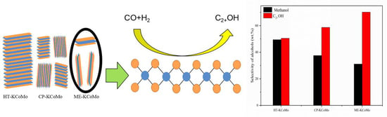
Effect of KCoMoS2 Catalyst Structures on the Catalytic Performance of Higher Alcohols Synthesis via CO Hydrogenation

1
State Key Laboratory of Coal Conversion, Institute of Coal Chemistry, Chinese Academy of Sciences, Taiyuan 030001, Shanxi, China
2
University of Chinese Academy of Science, Beijing 100049, China
*
Author to whom correspondence should be addressed.
Catalysts 2020, 10(2), 151; https://doi.org/10.3390/catal10020151
Submission received: 9 January 2020 / Revised: 18 January 2020 / Accepted: 22 January 2020 / Published: 25 January 2020
(This article belongs to the Special Issue Advanced Nanomaterials - Synthesis and Applications in Catalysis)

Abstract

:
Different structures of cobalt and potassium modified molybdenum sulfide catalyst (KCoMoS2) were synthesized by hydrothermal synthesis, coprecipitation and reverse microemulsion methods. Nitrogen adsorption, XRD, TEM, XPS and HAADF-STEM-EDS techniques were used to characterize the catalysts structures. The results indicate that the molybdenum sulfide-based catalyst synthesized by the reverse microemulsion method possessed less sheets with small lateral dimensions, while the catalysts prepared by the former two methods contained a higher number of stacking MoS2 layers. In the test of higher alcohol synthesis from CO hydrogenation, it was found that the catalyst synthesized by the reverse microemulsion method exhibited the best CO conversion and C2+OH selectivity among the prepared catalysts. The correlation study between the catalysts structure and the reaction properties implies that the shorter and thinner molybdenum sulfide sheet structure favored for the exposure of the active sites, which, in turn, brought about an enhanced CO conversion and more C2+OH formation.

Graphical Abstract

1. Introduction

With the shortage of petroleum resources, finding production routes for alternative fuels and the optimization of energy structure are of great significance for mitigating energy and environmental protection pressures as well as sustainable economic development [1,2]. Converting coal- or biomass-based syngas into higher alcohols from CO hydrogenation is considered as one of the alternative fuels production routes due to the fact that alcohol products can be directly used as automobile fuel additives or liquid fuel [3]. Moreover, the higher alcohols, after separation and purification, can serve as feed stocks for value-added fine chemicals, demonstrating a wide application prospect [4]. Generally, the catalytic production process for higher alcohols synthesis from syngas needs to occur over the solid catalysts, which are roughly classified into the following four categories: modified methanol synthesis catalysts [5,6], modified Fischer-Tropsch synthesis catalysts [7,8], noble metal ruthenium-based catalysts [9,10], and molybdenum sulfide-based catalysts [11,12]. Among these catalyst systems, the modified methanol synthesis catalyst mainly produced methanol with a lower C2+OH selectivity. The copper modified Fischer-Tropsch synthesis catalyst suffers from phase separation and active metal sintering, causing lots of hydrocarbon by-products. The ruthenium-based noble metal catalyst mainly affords C2+ oxygenates formation, but the scarcity and expensive cost restrict their practical application. The molybdenum sulfide-based catalyst demonstrated good sulfur resistance, strong carbon deposition resistance, long stabilization time and favorable C2+OH selectivity [13,14,15,16], so it has attracted particular interest in the research of higher alcohol synthesis (HAS) via CO hydrogenation.
As it is known that pure molybdenum sulfide usually can be served as a good methanation catalyst [17]. For the higher alcohols’ synthesis via syngas, alkali metals or transitional metal promoters are usually introduced into molybdenum sulfide [18]. The general role of alkali metals can prevent the dissociative adsorption of CO on the active sites and favor the non-dissociative adsorption of CO to form more alcohols [19]. Theoretically, Cs has a large ionic radius and strong alkalinity, and the positive effect for higher alcohol synthesis is the most obvious among the alkali metals. But from a practical point of view, K is commonly used due to its abundant reserves and cheaper price [20]. Moreover, it has been thoroughly reported that the introduction of F-T components (Fe, Co, Ni, etc.) in K-modified MoS2-based catalyst has a significant effect on the selectivity of C2+OH [21]. In particular, the introduction of cobalt can lead to considerable changes in the structure of K-MoS2 catalysts and promote the growth of alcoholic carbon-chains with more C1 intermediates transformation into C2 alcohols. In the synthesis of higher alcohols from syngas, it is commonly accepted that the active center of MoS2-based catalyst is located at the edge and corners of molybdenum sulfide [22,23], instead of the basal plane of the sheet. Therefore, the exposure of more edges and corners can facilitate the efficient conversion of syngas to higher alcohols [24,25,26]. However, the traditional Co promoted K-MoS2 catalysts usually have more stacking of MoS2 layers with a large geometrical size, causing less exposure of the edged and angular positioned active sites. Moreover, the excessive addition of Co may also produce more or less Co9S8 species, which cause more dissociative adsorption of CO and H2, favorable for the production of hydrocarbon by-products with less activity of alcohol synthesis [27,28].
To overcome the negative effect of thick stacking of MoS2 layers and Co9S8 species in higher alcohol synthesis, some researchers tried various preparation methods to prepare the nano-sized molybdenum sulfide-based catalysts with a smaller number and a shorter length of MoS2 sheets, as well as minimizing the generation of Co9S8 species. Li et al. [29] prepared a nanosheet-structured K-Co-MoS2 catalyst using hydrothermal synthesis and found no obvious Co9S8 generated, but the number of MoS2 layers was still thicker. Zhang et at. [30] obtained a thinner layer of MoS2 species by changing the acidic conditions. However, there was a larger amount of Co9S8 phase formed after introducing Co species in the MoS2 based catalyst.
Therefore, to improve the catalytic performance for HAS from CO hydrogenation, further efforts are still needed to prepare a more effective K-Co-MoS2 catalyst with a smaller crystal size and a lower number of stacked layers, but less Co9S8 content involved in the catalyst. In recent years, microemulsion methods have emerging for preparing nanoscaled catalysts [31,32]. The advantage of these methods is that they can better control the particle size distribution and morphology of the catalyst with no need for special or expensive equipment under mild pressure or temperature range [33,34]. Peculiarly, for the reverse microemulsion method, the synthesis reaction occurred in a system of extremely small water droplets coated by the oil phase, ensuring the formation of tiny catalyst particles. In the previous work of our group, we successfully synthesized the core-shell structured CuFe@SiO2 catalyst [35] using reverse microemulsion method, which exhibited the total alcohol selectivity of 34.6 wt% with C2+OH content above 57.7 wt%. Rodrigo et al. [36] prepared Ni-modified K-doped MoS2 catalyst by coprecipitation in microemulsion systems. It showed that the catalyst synthesized by this method has a lower crystallinity and better activity for higher alcohol synthesis. The above studies preliminarily displayed that the smaller nanoparticles of the catalyst can be well controlled in a reverse microemulsion system to accomplish a satisfying catalytic performance. These also encourage us to further construct different catalyst structures derived from various preparation methods and investigate the inherent effect of catalyst structures on the higher alcohol synthesis from CO hydrogenation.
Herein, in the present work, we prepared several potassium and cobalt promoted nano-molybdenum sulfide catalysts using the reverse microemulsion (ME-KCoMo), traditional hydrothermal synthesis (HT-KCoMo) and coprecipitation (CP-KCoMo) methods. The obtained catalysts were evaluated for the CO hydrogenation to higher alcohols and the catalysts were analyzed in combination with different catalyst characterization means. The purpose of this study was to elucidate the relationship between the structure of the MoS2-based catalyst and the reaction performance.

2. Results and Discussion

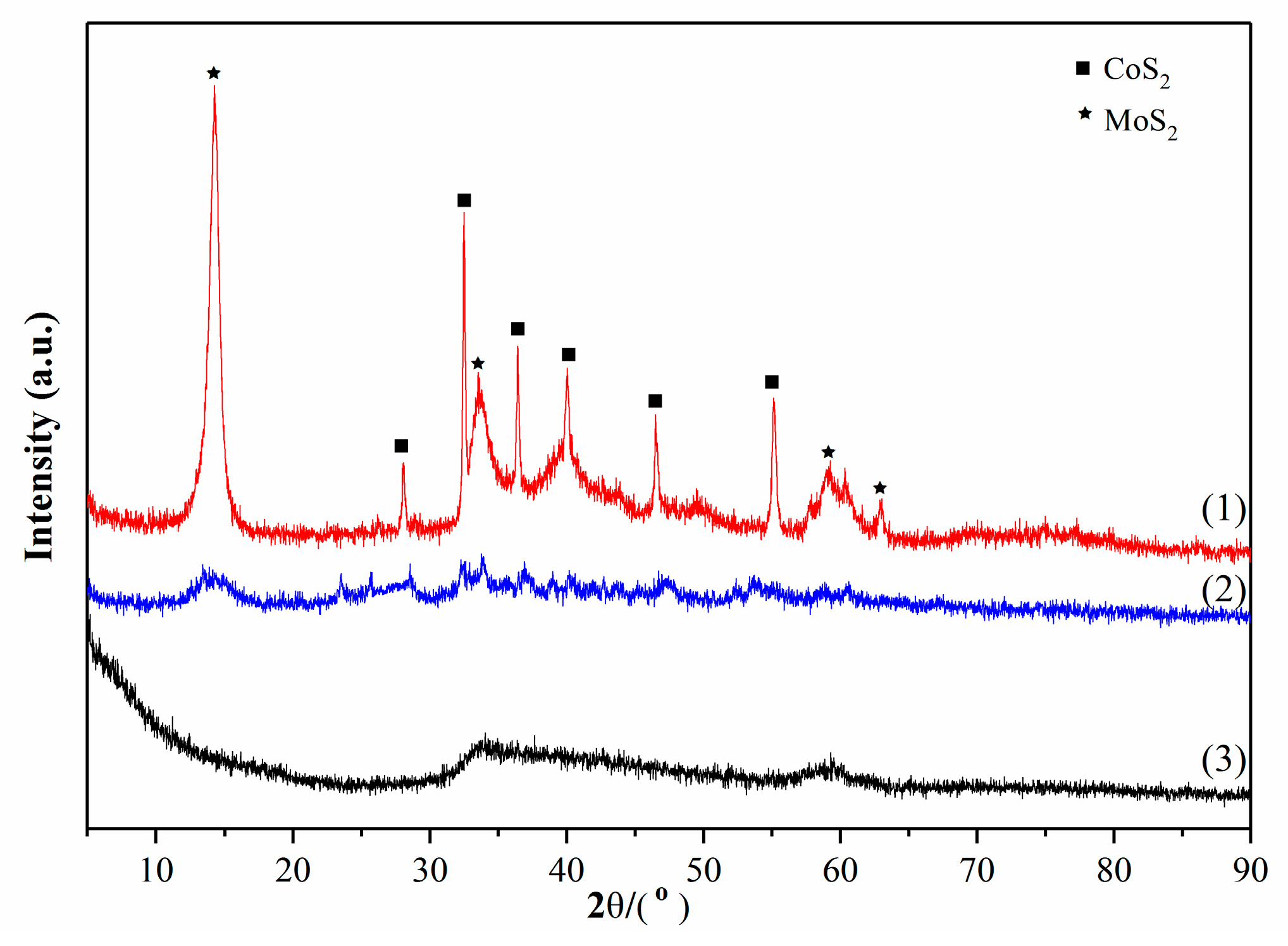
2.1. XRD and BET Results
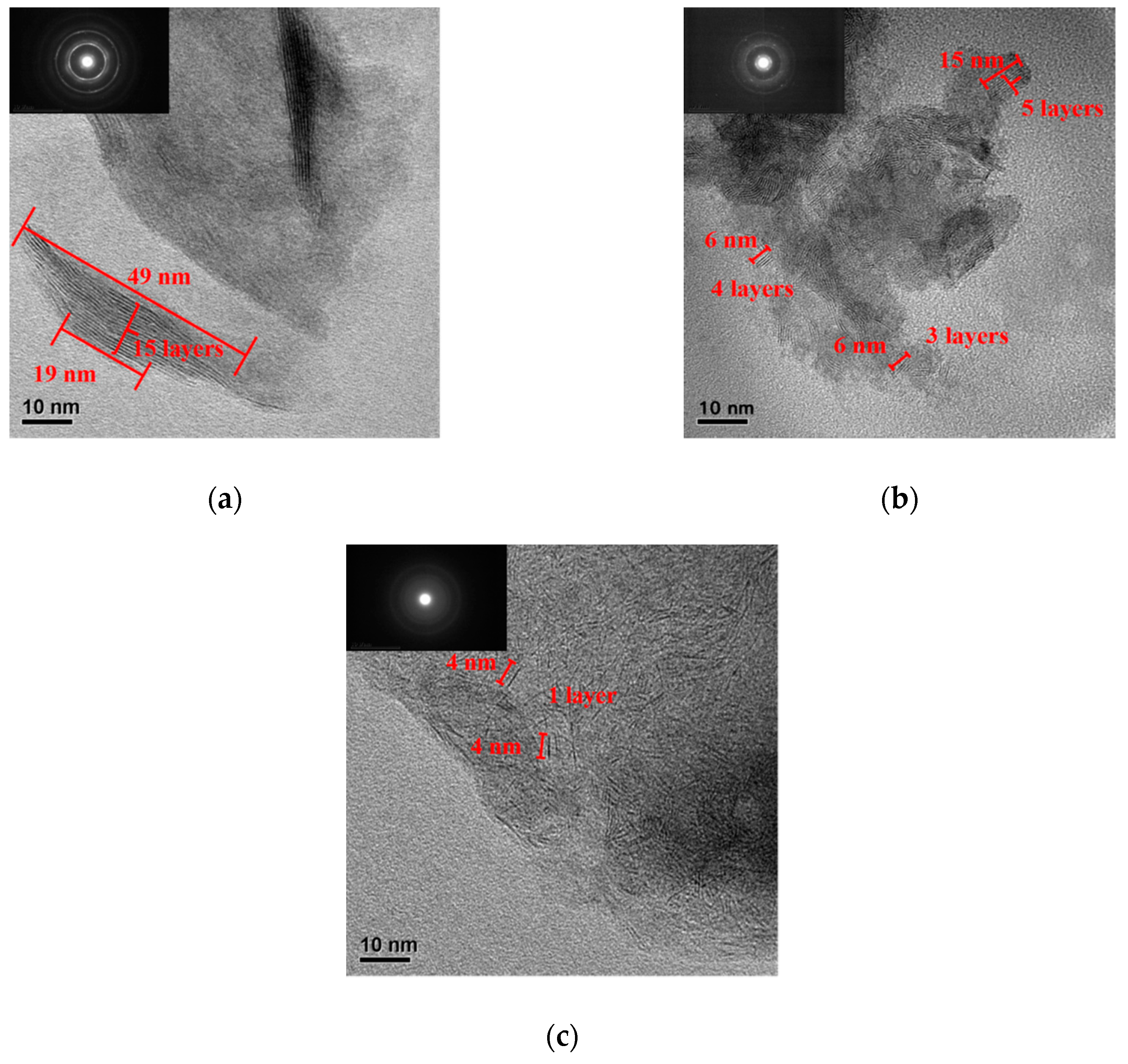
The XRD diffraction patterns of the catalysts are presented in Figure 1. It can be seen that the HT-KCoMo catalyst has six distinct peaks at 27.94°, 32.37°, 36.33°, 39.89°, 46.34° and 56.97° corresponding to CoS2. These diffraction peaks became much weaker for the CP-KCoMo catalyst and hardly observed over the ME-KCoMo sample. This indicates that the HT-KCoMo catalyst has the highest crystallinity. Note that no peaks assigned to Co9S8 phase can be seen over all the samples. According to the literature [29,37], Co9S8 is prone to be formed when the Co/Mo ratio reaches above 0.5. The nominal Co/Mo ratio for our prepared catalysts is 0.5, which is insufficient and limits the value during the Co9S8 phase.
The diffraction peaks appearing in 14.38°, 33.51° and 60.14° can be indexed to the MoS2 crystal phase (JCPDS 37-1492). Specially, the diffraction peak at 14.38° corresponds to the MoS2 (002) crystal plane. The HT-KCoMo sample shows the much stronger peak intensity of MoS2 (002) crystal plane than CP-KCoMo sample, further indicating the higher degree of crystallization for the former sample. The peak attributed to the MoS2 (002) crystal plane is not seen for ME-KCoMo, which may be due to the formation of a thinner MoS2 sheet layer synthesized by the ME method. For the other two characteristic diffraction peaks of the MoS2 crystal phase at 33.51° and 60.14°, the ME-KCoMo catalyst exhibited a broader peak with a lower intensity, which implies that the particle size of MoS2 is much smaller across the sample.
As shown in Table 1, the crystal sizes of HT-KCoMo, CP-KCoMo and ME-KCoMo catalysts were estimated to be 33.39 nm, 18.24 nm, and 14.70 nm, respectively. Since the particle size of ME-KCoMo catalyst was the smallest, we speculate that the active species were highly dispersed over the catalyst. The texture properties of the KCoMo catalyst with different methods are also compared in Table 1. Nitrogen adsorption-desorption isotherm and BJH pore size distribution of catalysts were shown in Figures S1 (Supplementary Materials). Among them, ME-KCoMo had the largest specific surface area, the smallest pore diameter and particle diameter, while HT-KCoMo possessed the smallest ones, implying that the textural properties of the catalysts were significantly affected by the synthesis method. Generally, smaller particle sizes and larger specific surface areas are beneficial for exposing more corners and defects, which is conducive to the catalytic conversion of syngas.

2.2. TEM Results

The structures of HT-KCoMo, CP-KCoMo, and ME-KCoMo catalysts were characterized by the TEM technique. Figure 2a shows that the number of MoS2 layers in the HT-KCoMo catalyst exceeds 15 layers, and its length is 19–49 nm. This indicates that the crystallinity of MoS2 is high. It can be seen from Figure 2b that the CP-KCoMo catalyst exhibited short-grained MoS2 sheets with 3–5 layers and the length of the MoS2 sheets was significantly shorter (6–15 nm) than that of HT-KCoMo. Compared with the former two catalysts, the ME-KCoMo sample exemplified a more scattered mostly single layer with a much shorter length of MoS2 sheets (see Figure 2c). This indicated that compared with the hydrothermal synthesis and the coprecipitation methods, the reverse microemulsion method could obtain a much larger number of thin and short nanosheet-structure of MoS2, which contributed to the exposure of the side and corners of the crystals. The SAED patterns (Figure 2a–c inset) imply that the MoS2 nanoparticles over the samples were polycrystalline. It can be seen that the crystallinity of the catalyst displayed the descending order of HT-KCoMo > CP-KCoMo > ME-KCoMo, which is also consistent with the results obtained by the XRD analysis.

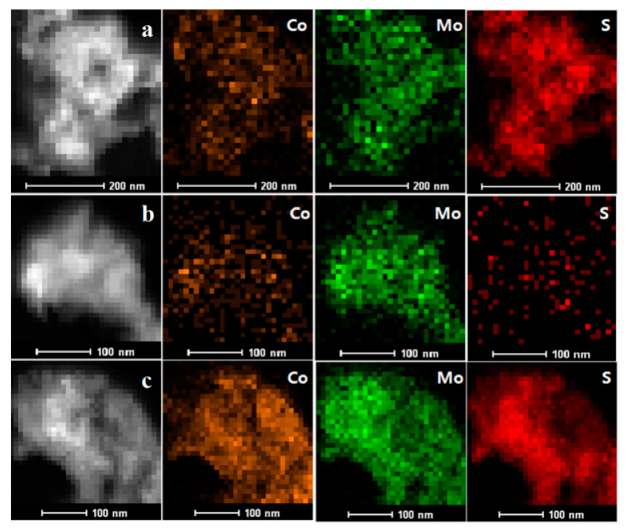
2.3. HAADF-STEM-DES Results

Figure 3 shows the HAADF-STEM-DES photos of the catalysts. Based on the feed ratio mentioned in the catalyst preparation process, we expected the Co:Mo:S ratio on the catalyst surface to be 0.5:1:2. It can be seen that for ME-KCoMo catalyst, the Co, Mo and S elements were all well dispersed with a relatively larger amount of Mo and S content on the surface of the catalyst (Figure 3a). However, the element content distribution in the catalyst synthesized by hydrothermal synthesis and coprecipitation is largely different from what was expected. We could anticipate that this may lead to more Co9S8 generation, which was also confirmed by XPS analysis. For the HT-KCoMo catalyst, compared with Mo, the distribution ratio of Co and S elements was lower than expected (Figure 3b). As can be seen from Figure 3c, the ratio of Co and S species increased significantly on the surface of the CP-KCoMo catalyst. This implies that the surface elements distributed by the ME-KCoMo catalyst were more uniform, while for the HT-KCoMo and CP-KCoMo catalysts, more elements might be located in the bulk phase.

2.4. XPS Results

The chemical state and composition of the catalyst were obtained by XPS analysis. The XPS spectra of Mo 3d, S 2p and Co 2p levels of ME-KCoMo, HT-KCoMo and CP-KCoMo were shown in Figure 4a–c. For all the catalysts, the binding energies (BEs) of the Mo4+ 3d3/2 (232.1–233.1 eV), Mo4+ 3d5/2 (229.0–229.9 eV), Mo6+ 3d3/2 (236.5–235.7 eV) and Mo6+ 3d5/2 (233.6–232.5 eV) peaks were clearly found (see Figure 4a). The peak at 226–227 eV was ascribed to the satellite peak of S 2s. It could be observed that the Mo4+ and Mo6+ ions of the HT-KCoMo catalyst migrated to significantly higher BEs compared to those of the ME-KCoMo and the CP-KCoMo catalysts. A similar phenomenon was also seen for S2− 2p spectra in Figure 4b. This indicates that Mo and S species had higher electron densities on the ME-KCoMo and CP-KCoMo surfaces. For the XPS spectrum of Co 2p of the three catalysts (Figure 4c), the first peak groups were located at 779.0–779.6 eV and 794.0–794.6 eV, confirming the presence of CoS2 [38,39]. The second peak group at 782.0–782.6 eV and 798.2–799.0 eV was assigned to Co2+, and the third peak group at 786.2–786.6 eV and 803.4–804.7 eV was attributed to the satellite signal [40]. In addition, for HT-KCoMo, CP-KCoMo and ME-KCoMo catalysts, the binding energy gap between Co 2p3/2 and Mo4+ 3d5/2 is 549.7 eV, 550.0 eV, 550.0 eV, respectively, which is relatively close to the value of 550.0 eV, coinciding with the Co atoms located in the MoS2 phase, as reported in the literature [41,42]. This may be considered as the formation of the Co-Mo-S phase, where S atom was shared by Co and Mo. Compared with the CP-KCoMo and HT-KCoMo catalysts, the ME-KCoMo sample showed a stronger intensity of the Co 2p peak, indicated that more Co atoms in CoS2 migrated into MoS2 phase in the ME-KCoMo catalyst, similarly to the previously reported results [29]. It should be noted that no phase of Co9S8 was observed in XRD, but Co2+ at 782.0–782.6 eV and 798.2–799.0 eV in XPS spectrum could be classified as Co9S8 [33]. This indicates that the crystallinity of Co9S8 located on the catalyst surface is very low. Table 2 lists the surface atomic ratios of the three catalysts based on XPS analysis. The Mo:S:Co ratio of the catalyst obtained by the reverse microemulsion method was 1:2.16:0.46, consistently with the previous HAADF-STEM-EDS results. This is also close to the calculated ratio based on the amount of the feedstock during catalyst preparation, indicating that the surface element was well uniformly distributed for the catalyst prepared by the reverse microemulsion method.

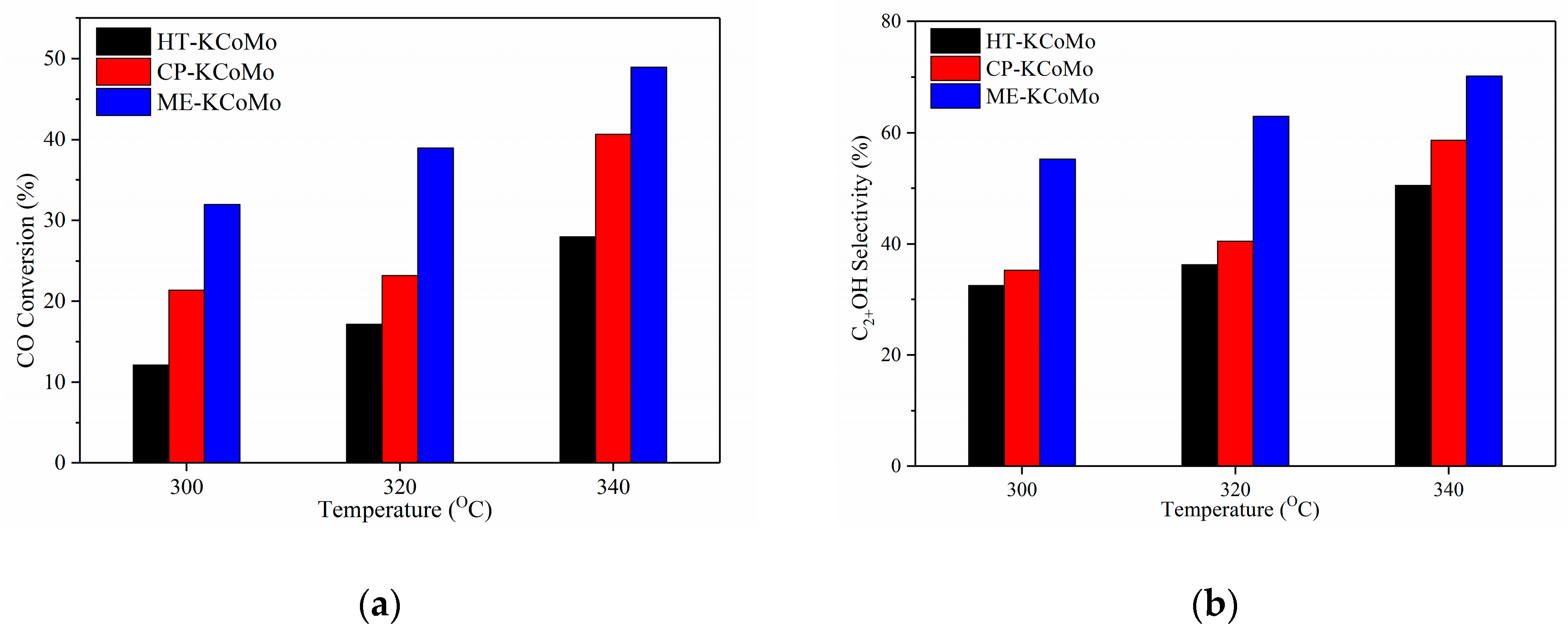
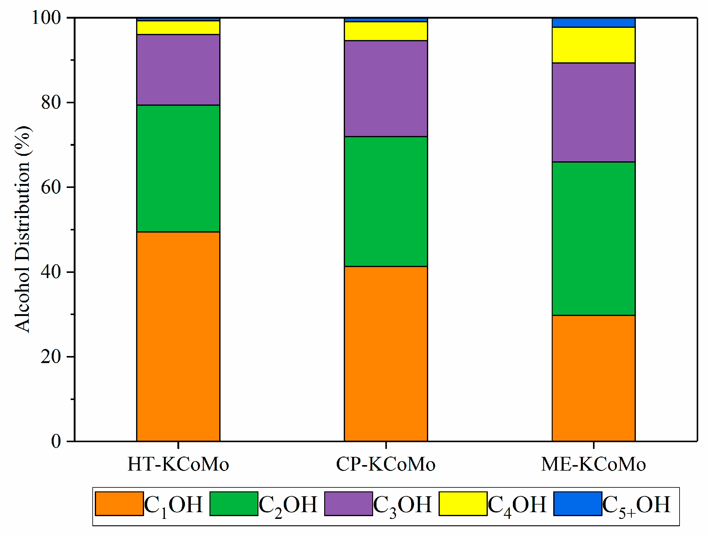
2.5. HAS Performances of the Catalysts

Figure 5a shows the changing trend of CO conversion over the catalysts in HAS reaction. For all the samples, the conversion of CO increased with the rise of the reaction temperature, which obeyed the general rule that occurred in most catalytic reactions. At the same reaction temperature, the ME-KCoMo catalyst gave the highest CO conversion followed by the CP-KCoMo and HT-KCoMo catalysts. In Figure 5b, the C2+OH selectivity among the three catalysts was compared. It could be seen that for each catalyst, the C2+OH selectivity declined with the sequence of HT-KCoMo < CP-KCoMo < ME-KCoMo catalysts, similarly to the change of CO conversion. From the above results, we could see that the ME-KCoMo catalyst exhibited the best CO conversion and C2+OH selectivity while the sample prepared by the hydrothermal method displayed the worst catalytic performance in the HAS reaction.
The main reason for the above reaction results might be ascribed to the distinct differences in the surface structures of the catalysts. According to the XRD and BET results, the ME-KCoMo catalyst had a lowest crystallinity and the largest specific surface area, indicating lots of smaller crystal particles with high dispersion formed on the catalyst in comparison with those over CP-KCoMo and HT-KCoMo catalysts. Combined with the catalytic performance shown in Figure 5, we speculated that the smaller catalyst particle with a higher dispersion facilitated CO conversion and C2+ alcohol selectivity. Ferrari et al. [43] found that fewer crystallites of MoS2 had a positive effect in the C2+OH selectivity in HAS, which is consistent with our results. From TEM images, the HT-KCoMo catalyst possessed a highly ordered layered structure with a thicker layer (15 layers) and a longer size (19–49 nm). As for CP-KCoMo and ME-KCoMo catalysts, the number of layers decreased sequentially, especially the latter catalyst, which had almost a single-layer structure with a particle size less than 5 nm. Claure et al. [25] reported that MoS2-based catalysts with smaller MoS2 layers had a higher selectivity for higher alcohols. Enlightened by such a report, we deemed that these thin and short layers for the ME-KCoMo catalyst could increase the exposure ratio of the sides, corners and basal surfaces of the catalyst, forming more active sites and then enhancing the catalytic performances. Moreover, Figure S2 (Supplementary Materials) shows the 200 h stability test of the ME-KCoMo catalyst prepared repeatedly. At the end of the reaction, there was no deactivation of the catalyst, which indicates that the catalyst has a good stability and repeatability.
The alcohol distribution over the three catalysts is shown in Figure 6. The content of C2OH, C3OH, C4OH, and C5+OH obtained over the three catalysts decreased in the order of ME-KCoMo > CP-KCoMo > HT-KCoMo, while methanol content showed the opposite trend. This indicates that the ME-KCoMo catalyst had a better carbon chain growth ability with respect to higher alcohol formation. Andersson et al. [19] suggested that the increase in CO conversion also led to the formation of long-chain alcohols, which is in agreement with our present evaluation results. For MoS2-based catalysts, it has been proven that the introduction of Co can increase the selectivity of higher alcohol [1], Co can modify the surface of MoS2 to form the Co-Mo-S phase. In our present work, the HAADF-STEM-EDS photos exhibited that the surface elements of the ME-KCoMo catalyst were more uniformly distributed. Moreover, based on the finding reported by Topsoe et al. [44] that Co primarily modifies the edges of MoS2, we presumed that the catalyst with a shorter size and single-layer structure was more conducive to the doping of MoS2 edges by Co atoms. From the XPS results, compared with CP-KCoMo and HT-KCoMo catalysts, ME-KCoMo catalyst possessed a larger amount of Co-Mo-S phases. It has been reported that the active H-species can be adsorbed on the Co-Mo-S site through hydrogen overflow and increase the rate of the hydrogenation reaction [45], then forming the active centers for a higher alcohol production. As a result, the KCoMo catalyst prepared by the reverse microemulsion method displayed a better catalytic performance with respect to CO conversion and C2+ alcohol selectivity.

3. Experimental

3.1. Catalyst Preparation

KCoMoS2 catalysts with Mo:Co:K of 2:1:1 (molar ratio) were synthesized by the reverse microemulsion method (ME), the traditional coprecipitation method (CP) and the hydrothermal synthesis method (HT), respectively.

3.1.1. Reverse Microemulsion Method

Firstly, 700 mL cyclohexane, 70 mL Triton X-100, and 35 mL n-hexanol was mixed by vigorously stirring to form a uniform mixture solution. Then, ammonium sulfide ((NH4)2S, 6.2 g), ammonium heptamolybdate ((NH4)6Mo7O24·4H2O, 4.0 g) and cobaltous nitrate (Co(NO3)2·6H2O, 3.0 g) were dissolved into a certain amount of distilled water, mixed together and added into the above mixture solution, stirring at room temperature for 30 min. The resulting solid was collected by centrifugation, followed by washing with absolute ethanol three times, dried overnight at 70 °C and then calcined at 400 °C for 4 h under Ar flow. Alkali doping was proceeded by mechanically mixing the thermal treated sample with K2CO3. The final obtained catalyst was defined as ME-KCoMo.

3.1.2. Traditional Coprecipitation Method

The catalyst step prepared by the coprecipitation method is basically similar to the reverse microemulsion method except that this is a reaction occurring in an aqueous solution. (NH4)2S (6.2 g), (NH4)6Mo7O24·4H2O (4.0 g) and Co(NO3)2·6H2O (3.0 g) were dissolved into a certain amount of distilled water, mixed together. The subsequent steps are consistent with the preparation of the ME-KCoMo catalyst. The final catalyst obtained was named CP-KCoMo.

3.1.3. Hydrothermal Synthesis Method

A certain amount of (NH4)6Mo7O24·4H2O (8.0 g), thiourea (CS(NH2)2, 13.7 g) and Co(NO3)2·6H2O (6.0 g) was firstly dissolved in distilled water, magnetically stirring for 15 min to form the uniform aqueous mixture solution. Then, the solution was transferred into a 120 mL Teflon-lined stainless-steel autoclave and thermally treated at 200 °C for 24 h. The subsequent steps were consistent with the preparation of ME-KCoMo catalyst. The finally obtained catalyst was designated as HT-KCoMo.

3.2. Characterization

X-ray diffraction (XRD) measurements of the catalysts were measured on D8 Advance Bruker AXS diffractometer (Karlsruhe, Germany) using Cu radiation at 40 kV and 100 mA, scanning from 5° to 90°. The specific surface area, pore volume and average pore size of the catalyst was measured using N2 adsorption–desorption isotherms (JW-BK200, Beijing, China) at liquid N2 temperature. Transmission electron microscopy (TEM) images of the samples and high angle annular dark field scanning transmission electron microscopy (HAADF-STEM surface scanning were obtained by a JEM-2100F microscope (Tokyo, Japan) operating at 200 kV. X-ray photoelectron spectroscopy (XPS) tests of the samples were carried out using a Thermo ESCALAB 250Xi spectrometer (Waltham, MA, USA), an operating voltage of 12.5 kV, and a filament current of 16 mA. The calibration was done with the C 1s peak at 284.80 eV.

3.3. Catalyst Evaluation

Catalyst (1.5 mL, 60 mesh) was diluted and mixed with an equal amount of quartz particles (60 mesh), charging into a pressured fixed-bed reactor for catalyst evaluation. After catalyst loading, the reactor pressure was increased to 6.0 MPa with syngas (H2/CO ratio of 2:1), a space flow rate (GHSV) of 2000 h−1, and then heated to a reaction temperature of 300–340 °C. The H2, CO in the exhaust gas was analyzed by a carbosieve-packed column with a TCD and the hydrocarbon product was analyzed by an Al2O3 column with an FID. The liquid phase product of the reaction was tested by two Porapak-Q columns (Santa Clara, CA, USA) equipped with a TCD and FID. Methanol and water were detected by TCD, and C1-5OH was detected by FID. For each catalyst test, the reaction products were collected after maintaining steady state for 24 h. The mass and carbon balance remained between 95% and 105%.

4. Conclusions

In summary, KCoMoS2 catalysts of different structures were synthesized by hydrothermal synthesis, coprecipitation and reverse microemulsion methods. The characterization results confirm that the reverse microemulsion method afforded the catalyst with a thinner and shorter MoS2 sheet structure, while the hydrothermal synthesis and coprecipitation methods gave a larger amount of stacking MoS2 layers. In the test of higher alcohol synthesis from CO hydrogenation, the catalyst derived from the reverse microemulsion method demonstrated higher CO conversion and C2+OH alcohol selectivity than those obtained from hydrothermal synthesis and coprecipitation methods. The study further reveals that the KCoMoS2 catalysts with a smaller particle size, fewer numbers of layers and shorter length of MoS2 nanosheets could expose more active sides and corners, which served as active sites and then improved the catalytic performance for higher alcohol synthesis via CO hydrogenation.

Supplementary Materials

The following are available online at https://www.mdpi.com/2073-4344/10/2/151/s1, Figure S1: Nitrogen adsorption-desorption isotherm and BJH pore size distribution of catalysts; Figure S2: ME-KCoMo catalyst stability test. Reaction conditions T = 340 °C, P = 6 MPa, GHSV = 2000 h−1, H2/CO = 2.0.

Author Contributions

Conceptualization, N.Q. and X.M.; methodology, N.Q.; validation, N.Q. and X.M.; formal analysis, N.Q.; investigation, N.Q. and X.M.; resources, K.F.; writing—original draft preparation, N.Q.; writing—review and editing, K.F. and L.Z.; visualization, N.Q.; supervision, K.F.; project administration, K.F. All authors have read and agreed to the published version of the manuscript.

Funding

This research was funded by the National Key R&D Program of China (2018YFB0604700), National Natural Science Foundation of China (21978313, 21603255, 21473230).

Acknowledgments

This work was financially supported by the National Key R&D Program of China (2018YFB0604700), National Natural Science Foundation of China (21978313, 21603255, 21473230).

Conflicts of Interest

The authors declare no conflict of interest. The funders had no role in the design of the study; in the collection, analyses, or interpretation of data; in the writing of the manuscript, or in the decision to publish the results.

References

  1. Spivey, J.J.; Egbebi, A. Heterogeneous catalytic synthesis of ethanol from biomass-derived syngas. Chem. Soc. Rev. 2007, 36, 1514–1528. [Google Scholar] [CrossRef]
  2. Subramani, V.; Gangwal, S.K. A review of recent literature to search for an efficient catalytic process for the conversion of syngas to ethanol. Energ. Fuel. 2008, 22, 814–839. [Google Scholar] [CrossRef]
  3. Von Blottnitz, H.; Curran, M.A. A review of assessments conducted on bio-ethanol as a transportation fuel from a net energy, greenhouse gas, and environmental life cycle perspective. J. Clean. Prod. 2007, 15, 607–619. [Google Scholar] [CrossRef]
  4. Surisetty, V.R.; Dalai, A.K.; Kozinski, J. Alcohols as alternative fuels: An overview. Appl. Catal. A Gen. 2001, 404, 1–11. [Google Scholar] [CrossRef]
  5. Li, X.; Zhang, J.; Zhang, M.; Zhang, W.; Zhang, M.; Xie, H.; Wu, Y.; Tan, Y. The support effects on the direct conversion of syngas to higher alcohol synthesis over copper-based catalysts. Catalysts 2019, 9, 199. [Google Scholar] [CrossRef] [Green Version]
  6. Heracleous, E.; Liakakou, E.T.; Lappas, A.A.; Lemonidou, A.A. Investigation of K-promoted Cu-Zn-Al, Cu-X-Al and Cu-Zn-X (X= Cr, Mn) catalysts for carbon monoxide hydrogenation to higher alcohols. Appl. Catal. A Gen. 2013, 455, 145–154. [Google Scholar] [CrossRef]
  7. Guo, S.; Liu, G.; Han, T.; Zhang, Z.; Liu, Y. K-Modulated Co nanoparticles trapped in La-Ga-O as superior catalysts for higher alcohols synthesis from syngas. Catalysts 2019, 9, 218. [Google Scholar] [CrossRef] [Green Version]
  8. Zhao, L.; Duan, J.; Zhang, Q.; Li, Y.; Fang, K. Preparation, Structural Characteristics, and Catalytic Performance of Cu–Co Alloy Supported on Mn–Al Oxide for Higher Alcohol Synthesis via Syngas. Ind. Eng. Chem. Res. 2018, 57, 14957–14966. [Google Scholar] [CrossRef]
  9. Yu, J.; Mao, D.; Han, L.; Guo, Q.; Lu, G. CO hydrogenation over Fe-promoted Rh–Mn–Li/SiO2 catalyst: The effect of sequences for introducing the Fe promoter. Fuel Process. Technol. 2013, 112, 100–105. [Google Scholar] [CrossRef]
  10. Chen, W.; Ding, Y.; Xue, F.; Song, X.; Ning, L. Highly efficient β-SiC-supported 0.5% Rh-based catalyst for CO hydrogenation to C2 oxygenates. Catal. Commun. 2016, 85, 44–47. [Google Scholar] [CrossRef]
  11. Luan, X.; Yong, J.; Dai, X.; Zhang, X.; Qiao, H.; Yang, Y.; Huang, X. Tungsten-doped molybdenum sulfide with dominant double-layer structure on mixed MgAl oxide for higher alcohol synthesis in CO hydrogenation. Ind. Eng. Chem. Res. 2018, 57, 10170–10179. [Google Scholar] [CrossRef]
  12. Zhang, F.; Li, Y.; Gao, S.; Fang, H.; Liang, X.; Yuan, Y. Synthesis of higher alcohols by CO hydrogenation on a K-promoted Ni–Mo catalyst derived from Ni–Mo phyllosilicate. Catal. Sci. Technol. 2018, 8, 4219–4228. [Google Scholar] [CrossRef]
  13. Christensen, J.M.; Mortensen, P.M.; Trane, R.; Jensen, P.A.; Jensen, A.D. Effects of H2S and process conditions in the synthesis of mixed alcohols from syngas over alkali promoted cobalt-molybdenum sulfide. Appl. Catal. A Gen. 2009, 366, 29–43. [Google Scholar] [CrossRef]
  14. Herman, R.G. Advances in catalytic synthesis and utilization of higher alcohols. Catal. Today 2000, 55, 233–245. [Google Scholar] [CrossRef]
  15. Koizumi, N.; Murai, K.; Ozaki, T.; Yamada, M. Development of sulfur tolerant catalysts for the synthesis of high quality transportation fuels. Catal. Today 2004, 89, 465–478. [Google Scholar] [CrossRef]
  16. Bao, J.; Fu, Y.; Sun, Z.; Gao, C. A highly active K-Co-Mo/C catalyst for mixed alcohol synthesis from CO + H2. Chem. Commun. 2003, 746–747. [Google Scholar] [CrossRef]
  17. Liu, J.; Wang, E.; Lv, J.; Li, Z.; Wang, B.; Ma, X.; Qin, S.; Sun, Q. Investigation of sulfur-resistant, highly active unsupported MoS2 catalysts for synthetic natural gas production from CO methanation. Fuel Process. Technol. 2013, 110, 249–257. [Google Scholar] [CrossRef]
  18. Zaman, S.; Smith, K.J. A review of molybdenum catalysts for synthesis gas conversion to alcohols: Catalysts, mechanisms and kinetics. Catal. Rev. 2012, 54, 41–132. [Google Scholar] [CrossRef]
  19. Andersson, R.; Boutonnet, M.; Järås, S. Correlation patterns and effect of syngas conversion level for product selectivity to alcohols and hydrocarbons over molybdenum sulfide based catalysts. Appl. Catal. A Gen. 2012, 417, 119–128. [Google Scholar] [CrossRef]
  20. Stevens, R.R.; Conway, M.M. Mixed alcohols production from syngas. U.S. Patent 4 831 060, 16 May 1989. [Google Scholar]
  21. Surisetty, V.R.; Eswaramoorthi, I.; Dalai, A.K. Comparative study of higher alcohols synthesis over alumina and activated carbon-supported alkali-modified MoS2 catalysts promoted with group VIII metals. Fuel 2012, 96, 77–84. [Google Scholar] [CrossRef]
  22. Jaramillo, T.F.; Jørgensen, K.P.; Bonde, J.; Nielsen, J.H.; Horch, S.; Chorkendorff, I. Identification of active edge sites for electrochemical H2 evolution from MoS2 nanocatalysts. Science 2007, 317, 100–102. [Google Scholar] [CrossRef] [PubMed] [Green Version]
  23. Daage, M.; Chianelli, R.R. Structure-function relations in molybdenum sulfide catalysts: The “rim-edge” model. J. Catal. 1994, 149, 414–427. [Google Scholar] [CrossRef]
  24. Morrill, M.R.; Thao, N.T.; Shou, H.; Davis, R.J.; Barton, D.G.; Ferrari, D.; Agrawal, P.K.; Jones, C.W. Origins of unusual alcohol selectivities over mixed MgAl oxide-supported K/MoS2 catalysts for higher alcohol synthesis from syngas. ACS Catal. 2013, 3, 1665–1675. [Google Scholar] [CrossRef]
  25. Claure, M.T.; Chai, S.H.; Dai, S.; Unocic, K.A.; Alamgir, F.M.; Agrawal, P.K.; Jones, C.W. Tuning of higher alcohol selectivity and productivity in CO hydrogenation reactions over K/MoS2 domains supported on mesoporous activated carbon and mixed MgAl oxide. J. Catal. 2015, 324, 88–97. [Google Scholar] [CrossRef] [Green Version]
  26. Li, Y.; Zhao, L.; Liu, X.; Zeng, C.; Fang, K. Preparation of KNiMo-based catalysts by using non-thermal plasma and their catalytic performance in the synthesis of higher alcohols from syngas. J. Fuel Chem. Technol. 2019, 47, 513–521. [Google Scholar] [CrossRef]
  27. Chianelli, R.R.; Berhault, G.; Torres, B. Unsupported transition metal sulfide catalysts: 100 years of science and application. Catal. Today 2009, 147, 275–286. [Google Scholar] [CrossRef]
  28. Okamoto, Y.; Shimokawa, T.; Imanaka, T.; Teranishi, S. X-ray photoelectron spectroscopy study of cobalt-molybdenum binary oxide catalysts. J. Catal. 1979, 57, 153–166. [Google Scholar] [CrossRef]
  29. Li, H.; Zhang, W.; Wang, Y.; Shui, M.; Sun, S.; Bao, J.; Gao, C. Nanosheet-structured K–Co–MoS2 catalyst for the higher alcohol synthesis from syngas: Synthesis and activation. J. Energy Chem. 2019, 30, 57–62. [Google Scholar] [CrossRef] [Green Version]
  30. Zhang, C.; Li, P.; Liu, X.; Liu, T.; Jiang, Z.; Li, C. Morphology-performance relation of (Co)MoS2 catalysts in the hydrodesulfurization of FCC gasoline. Appl. Catal. A Gen. 2018, 556, 20–28. [Google Scholar] [CrossRef]
  31. Chiang, S.J.; Liaw, B.J.; Chen, Y.Z. Preparation of NiB nanoparticles in water-in-oil microemulsions and their catalysis during hydrogenation of carbonyl and olefinic groups. Appl. Catal. A Gen. 2007, 319, 144–152. [Google Scholar] [CrossRef]
  32. Konarova, M.; Tang, F.; Chen, J.; Wang, G.; Rudolph, V.; Beltramini, J. Nano-and Microscale Engineering of the Molybdenum Disulfide-Based Catalysts for Syngas to Ethanol Conversion. ChemCatChem 2014, 6, 2394–2402. [Google Scholar] [CrossRef]
  33. Liu, M.; Li, X.; Xu, Z.; Li, B.; Chen, L.; Shan, N. Synthesis of chain-like MoS2 nanoparticles in W/O reverse microemulsion and application in photo catalysis. Chin. Sci. Bull. 2012, 57, 3862–3866. [Google Scholar] [CrossRef] [Green Version]
  34. Wei, B.; Wang, L.; Miao, Q.; Yuan, Y.; Dong, P.; Vajtai, R.; Fei, W. Fabrication of manganese oxide/three-dimensional reduced graphene oxide composites as the supercapacitors by a reverse microemulsion method. Carbon 2015, 85, 249–260. [Google Scholar] [CrossRef]
  35. Huang, C.; Zhang, M.; Zhu, C.; Mu, X.; Zhang, K.; Zhong, L.; Fang, K.; Wu, M. Fabrication of Highly Stable SiO2 Encapsulated Multiple CuFe Nanoparticles for Higher Alcohols Synthesis via CO Hydrogenation. Catal. Lett. 2018, 148, 1080–1092. [Google Scholar] [CrossRef]
  36. París, R.S.; Montes, V.; Boutonnet, M.; Järås, S. Higher alcohol synthesis over nickel-modified alkali-doped molybdenum sulfide catalysts prepared by conventional coprecipitation and coprecipitation in microemulsions. Catal. Today 2015, 258, 294–303. [Google Scholar] [CrossRef]
  37. Iranmahboob, J.; Hill, D.O. Alcohol synthesis from syngas over K2CO3/CoS/MoS2 on activated carbon. Catal. Lett. 2002, 78, 49–55. [Google Scholar] [CrossRef]
  38. Zhang, H.; Li, Y.; Zhang, G.; Xu, T.; Wan, P.; Sun, X. A metallic CoS2 nanopyramid array grown on 3D carbon fiber paper as an excellent electrocatalyst for hydrogen evolution. J. Mater. Chem. A 2015, 3, 6306–6310. [Google Scholar] [CrossRef]
  39. Zhu, L.; Susac, D.; Teo, M.; Wong, K.C.; Wong, P.C.; Parsons, R.R.; Bizzotto, D.; Mitchella, K.A.R.; Campbell, S.A. Investigation of CoS2-based thin films as model catalysts for the oxygen reduction reaction. J. Catal. 2008, 258, 235–242. [Google Scholar] [CrossRef]
  40. Dai, X.; Du, K.; Li, Z.; Liu, M.; Ma, Y.; Sun, H.; Zhang, X.; Yang, Y. Co-doped MoS2 nanosheets with the dominant CoMoS phase coated on carbon as an excellent electrocatalyst for hydrogen evolution. ACS Appl. Mater. Inter. 2015, 7, 27242–27253. [Google Scholar] [CrossRef]
  41. Nikulshin, P.A.; Ishutenko, D.I.; Mozhaev, A.A.; Maslakov, K.I.; Pimerzin, A.A. Effects of composition and morphology of active phase of CoMo/Al2O3 catalysts prepared using Co2Mo10–heteropolyacid and chelating agents on their catalytic properties in HDS and HYD reactions. J. Catal. 2014, 312, 152–169. [Google Scholar] [CrossRef]
  42. Alstrup, I.; Chorkendorff, I.; Candia, R.; Clausen, B.S.; Topsøe, H. A combined X-Ray photoelectron and Mössbauer emission spectroscopy study of the state of cobalt in sulfided, supported, and unsupported Co-Mo catalysts. J. Catal. 1982, 7, 397–409. [Google Scholar] [CrossRef]
  43. Ferrari, D.; Budroni, G.; Bisson, L.; Rane, N.J.; Dickie, B.D.; Kang, J.H.; Rozeveld, S.J. Effect of potassium addition method on MoS2 performance for the syngas to alcohol reaction. Appl. Catal. A Gen. 2013, 462, 302–309. [Google Scholar] [CrossRef]
  44. Topsøe, N.Y.; Topsøe, H. Characterization of the structures and active sites in sulfided Co-MoAl2O3 and Ni-MoAl2O3 catalysts by NO chemisorption. J. Catal. 1983, 84, 386–401. [Google Scholar] [CrossRef]
  45. Dong, K.; Ma, X.; Zhang, H.; Lin, G. Novel MWCNT-support for Co-Mo sulfide catalyst in HDS of thiophene and HDN of pyrrole. J. Nat. Gas. Chem. 2006, 15, 28–37. [Google Scholar] [CrossRef]
Figure 1. XRD patterns of the different MoS2-base catalysts. (1) HT-KCoMo; (2) CP-KCoMo; (3) ME-KCoMo.
Catalysts 10 00151 g001
Figure 2. TEM images of catalysts: (a) HT-KCoMo, (b) CP-KCoMo and (c) ME-KCoMo.
Catalysts 10 00151 g002
Figure 3. HAADF-STEM-EDS photographs of catalysts. (a) ME-KCoMo; (b) HT-KCoMo and (c) CP-KCoMo.
Catalysts 10 00151 g003
Figure 4. XPS spectra of (a) Mo 3d, (b) S 2p and (c) Co 2p. (1) ME-KCoMo; (2) CP-KCoMo and (3) HT-KCoMo.
Catalysts 10 00151 g004
Figure 5. Reaction results of HT-KCoMo, CP-KCoMo and ME-KCoMo catalysts under the same conditions. (a) CO conversion, (b) C2+OH selectivity. Reaction conditions T = 300–340 °C, P = 6 MPa, GHSV = 2000 h−1, H2/CO = 2.0.
Catalysts 10 00151 g005
Figure 6. Alcohol distribution over HT-KCoMo, CP-KCoMo and ME-KCoMo catalysts under the same conditions. Reaction conditions T = 340 °C, P = 6 MPa, GHSV = 2000 h−1, H2/CO = 2.0.
Catalysts 10 00151 g006
Table 1. Particle size, specific surface area, average pore size, pore volume of the catalysts.
CatalystParticle Size 1/nmSurface Area 2/(m2·g−1)Average Pore Size 2/(nm)Pore Volume 2/(cm3·g−1)
HT-KCoMo33.3911.009.830.07
CP-KCoMo18.2432.7010.690.15
ME-KCoMo14.7037.264.790.08
1 Calculated according to Scherrer equation. 2 Analysis using adsorption-desorption isotherms and BJH pore size distribution.
Table 2. Surface atomic ratio of ME-KCoMo, CP-KCoMo, and HT-KCoMo catalysts.
CatalystSurface Atomic Ratio
Mo:S:Co
ME-KCoMo1:2.16:0.46
CP-KCoMo1:2.22:0.81
HT-KCoMo1:2.14:0.25

