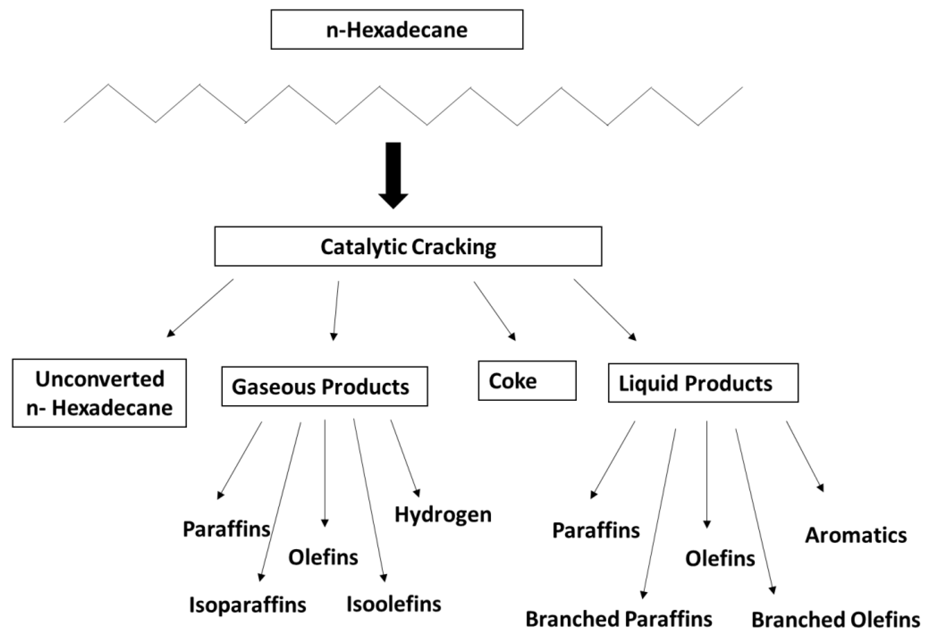
Catalytic Cracking of n-Hexadecane Using Carbon Nanostructures/Nano-Zeolite-Y Composite Catalyst

 ,
, 
 ,
, 
Abstract
1. Introduction
2. Results
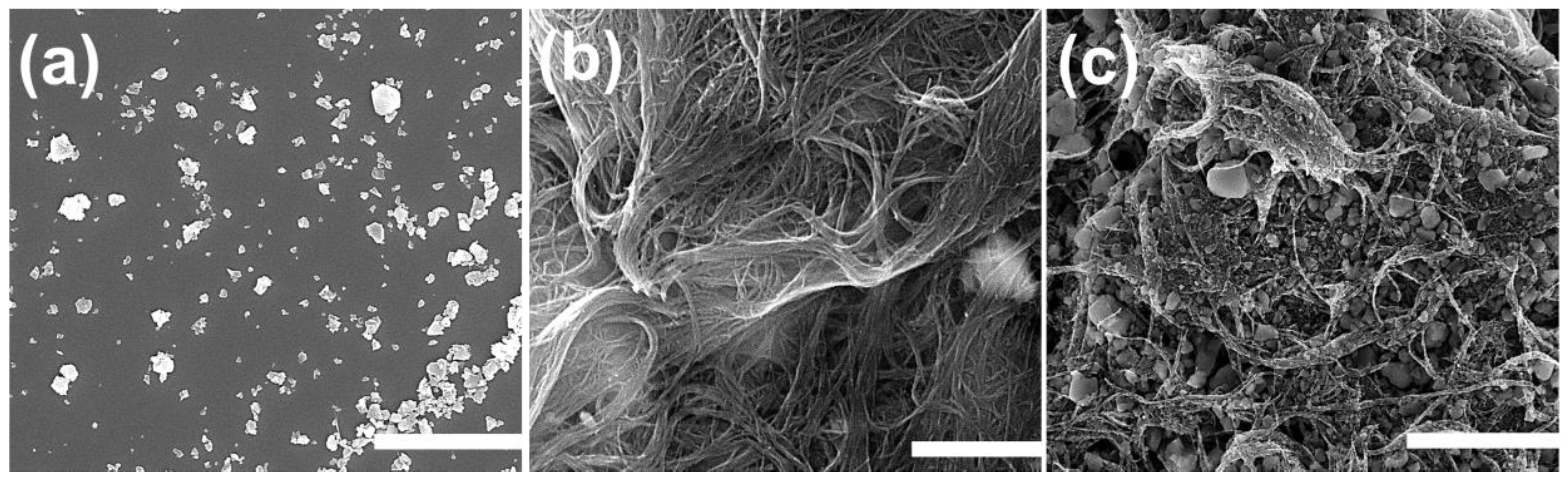
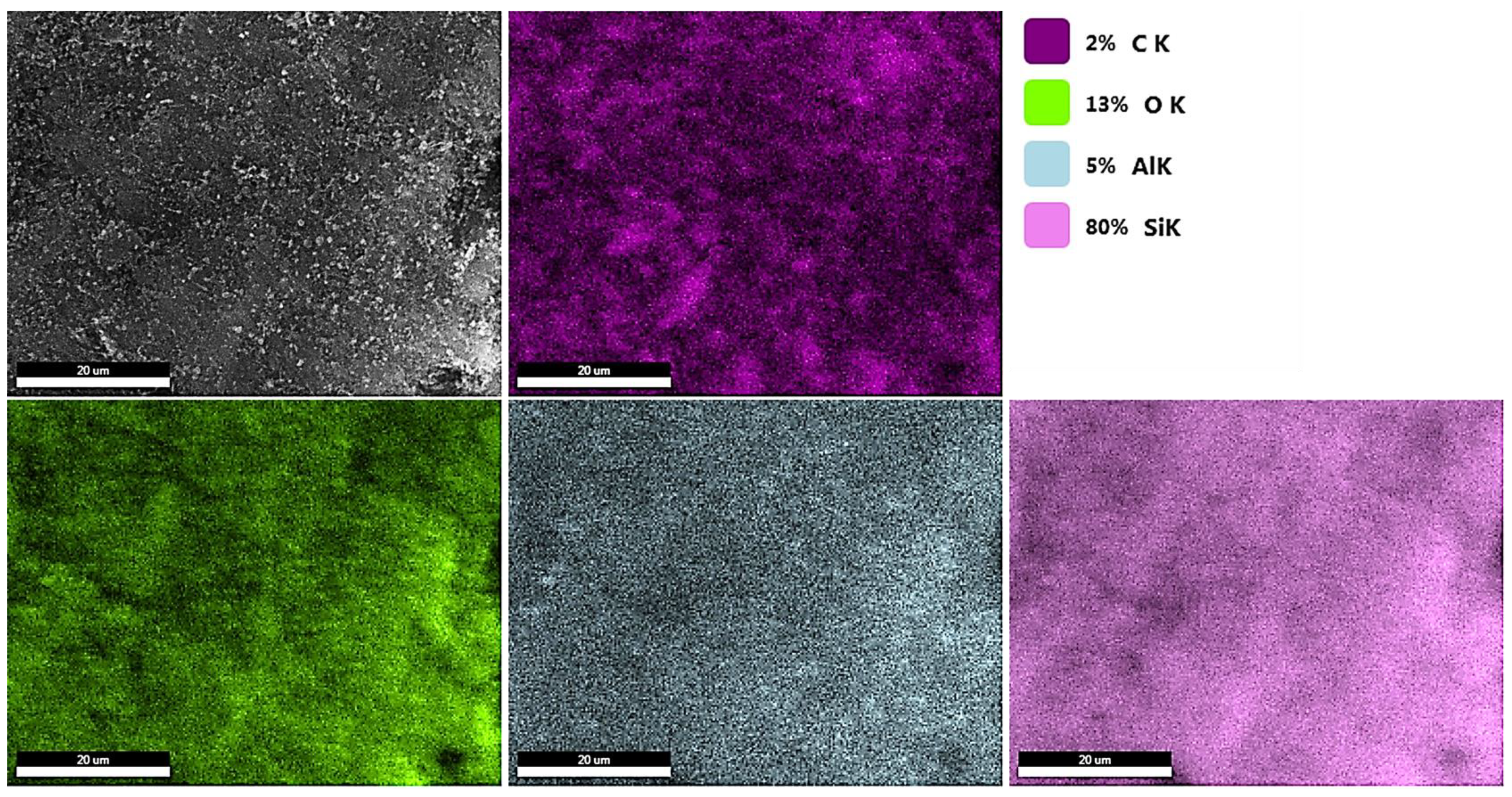
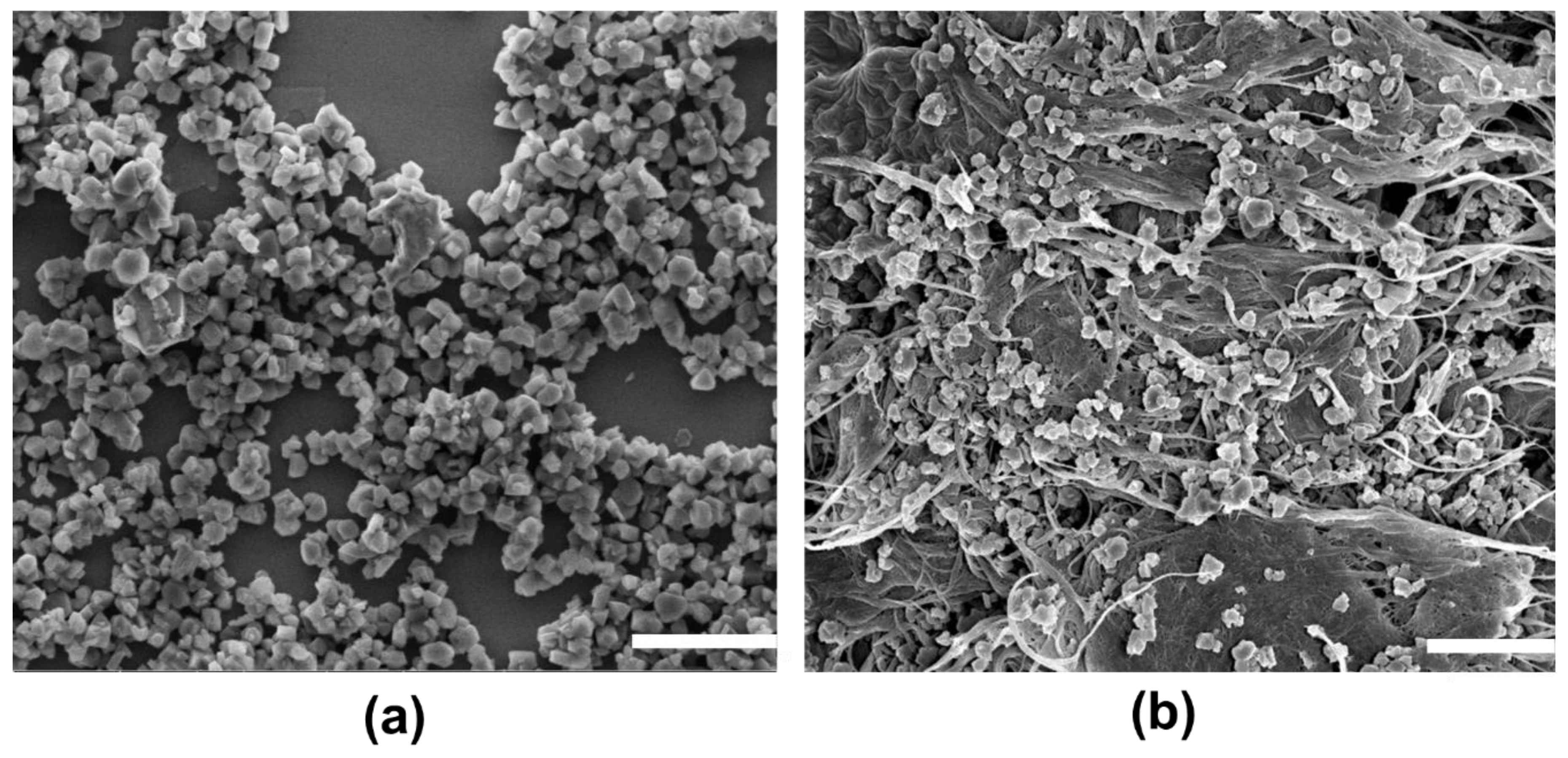
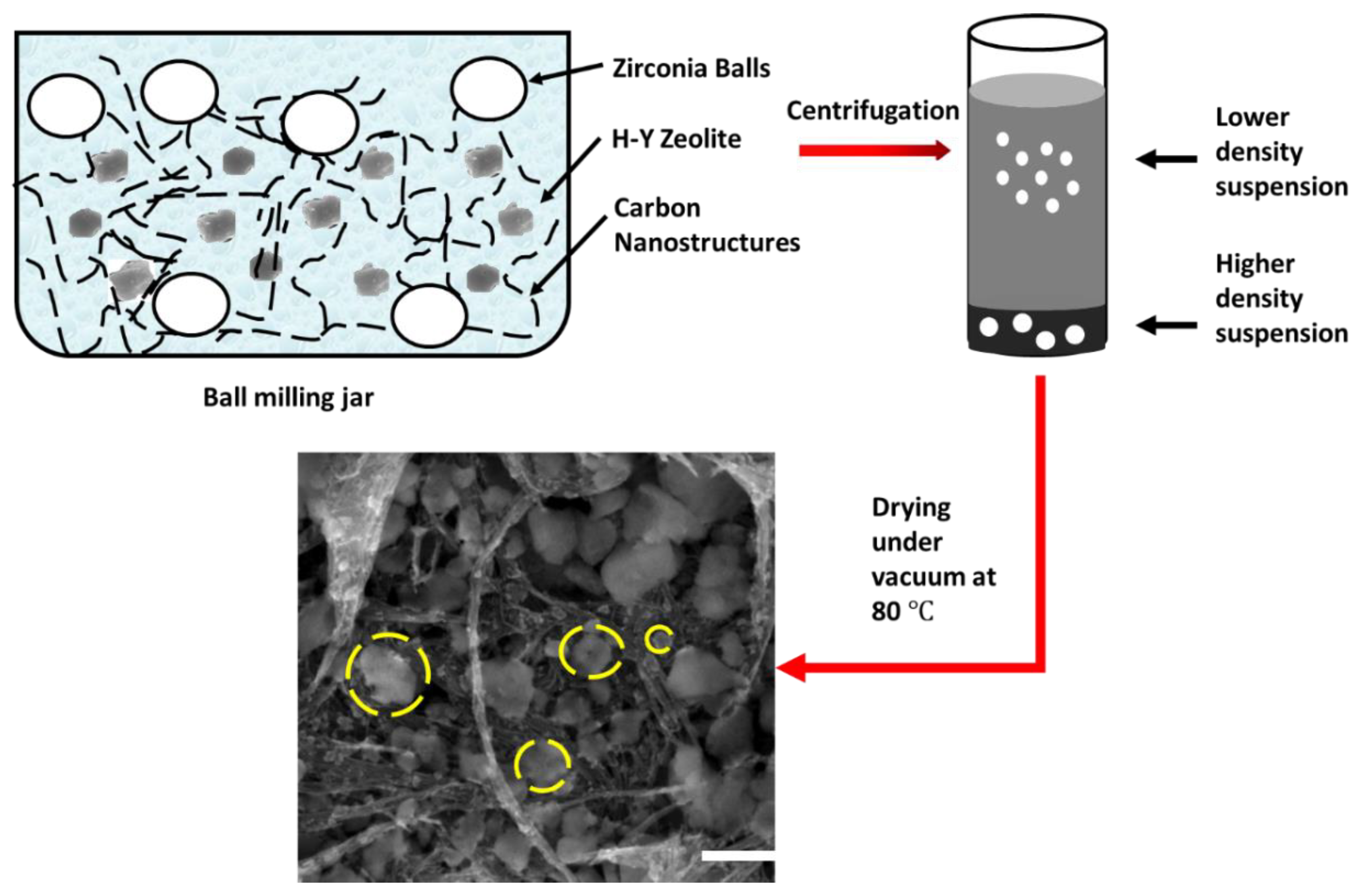
2.1. Surface Morphology and Elemental Mapping
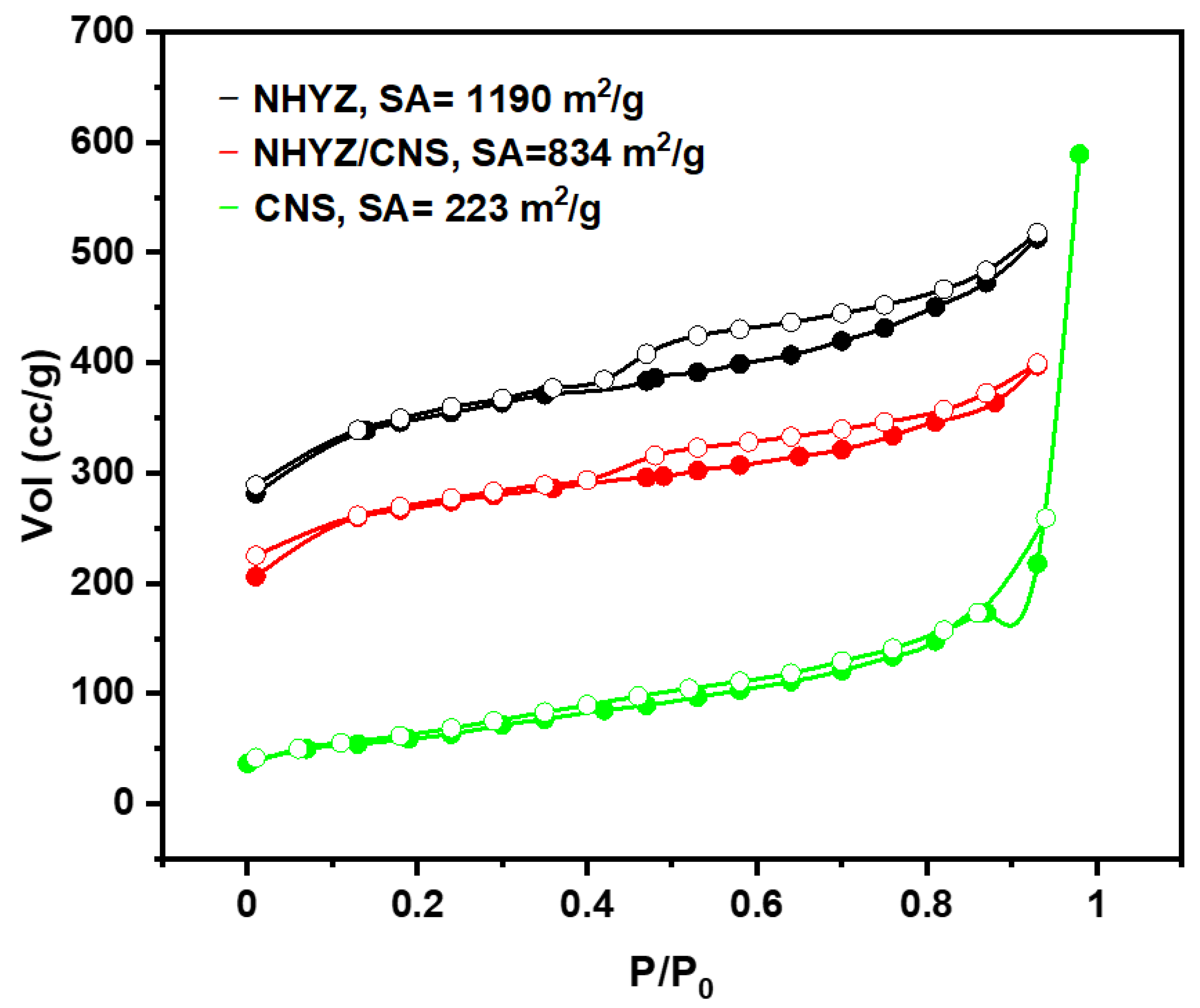
2.2. Surface Area
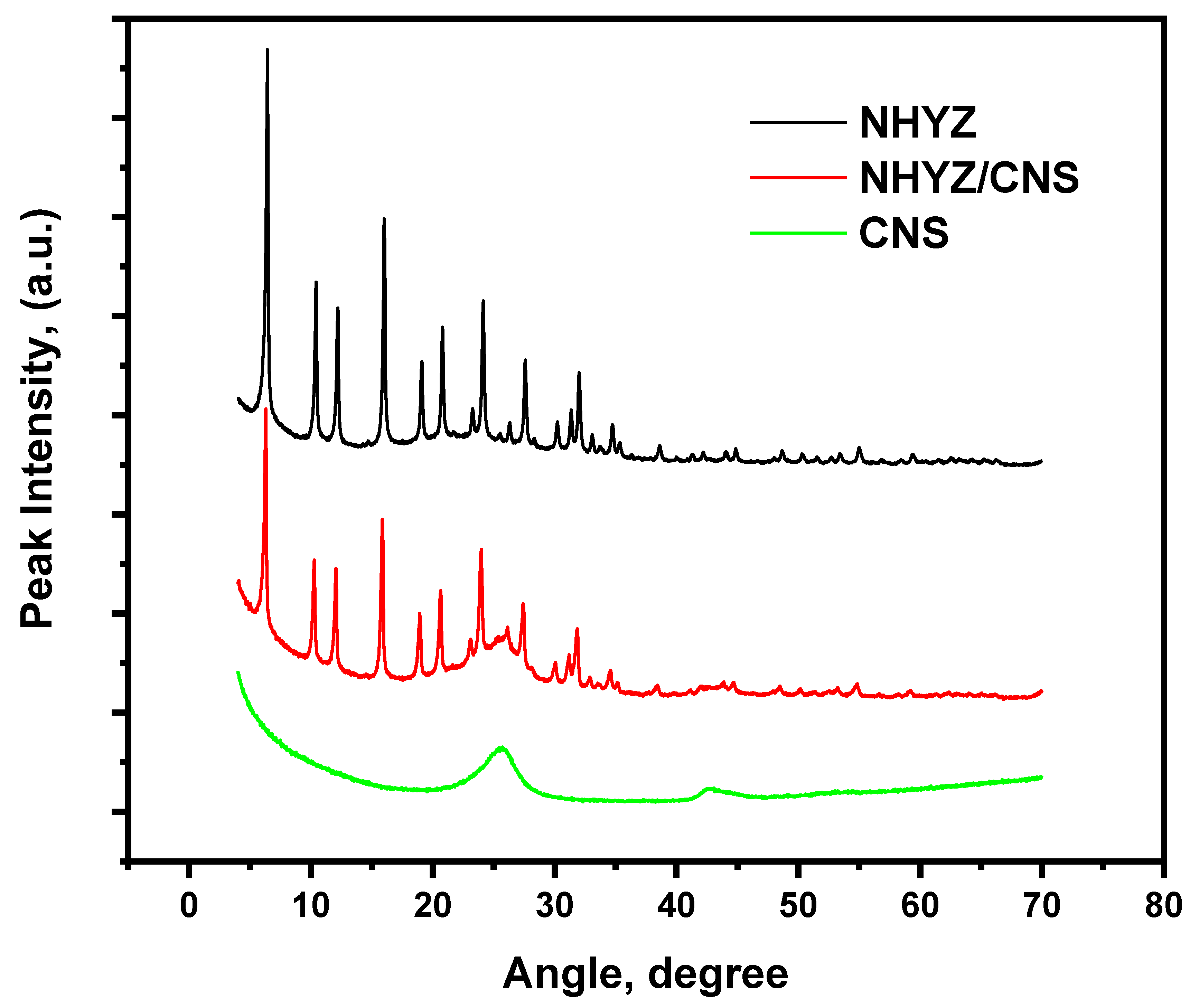
2.3. X-ray Diffraction Analysis
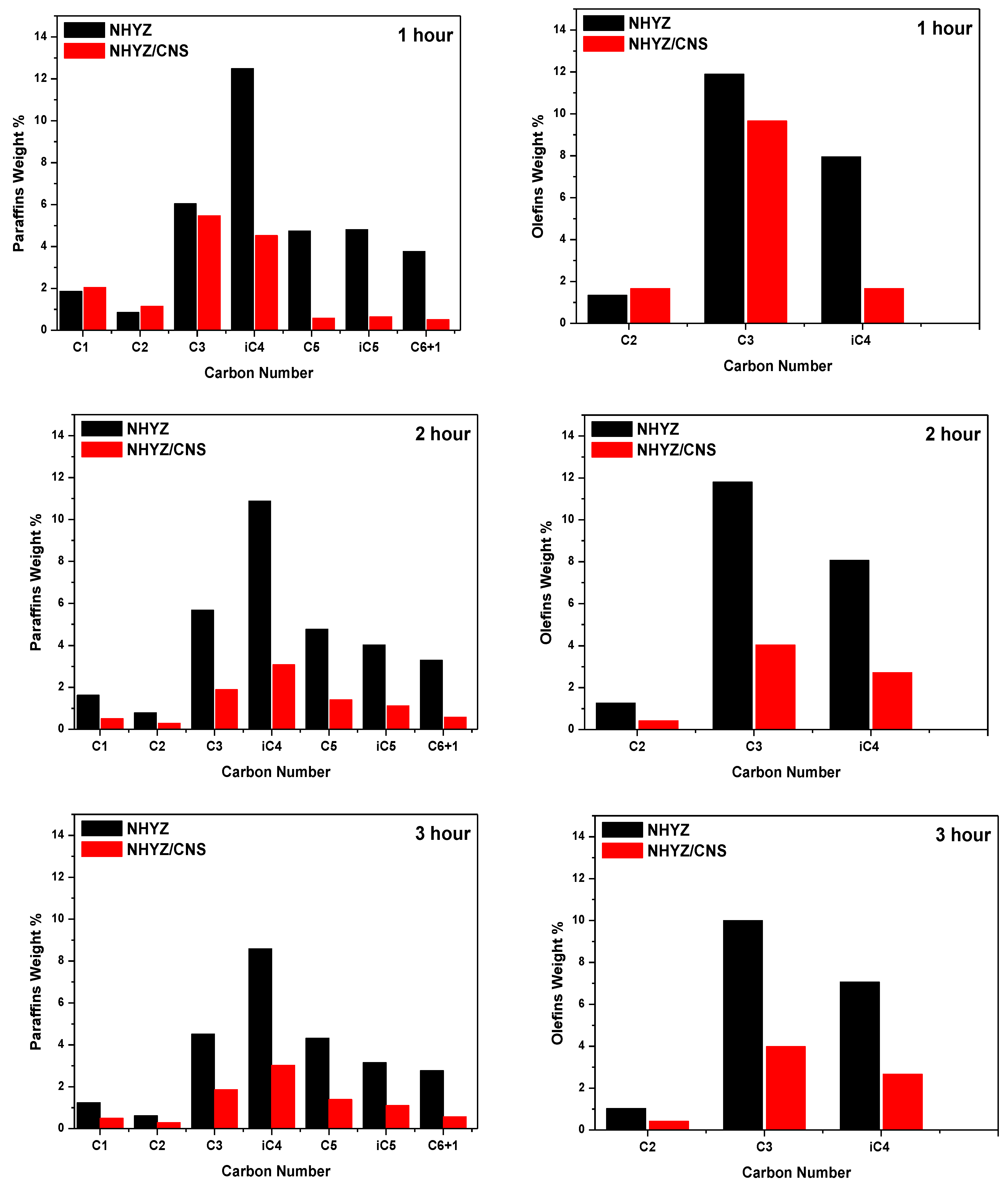
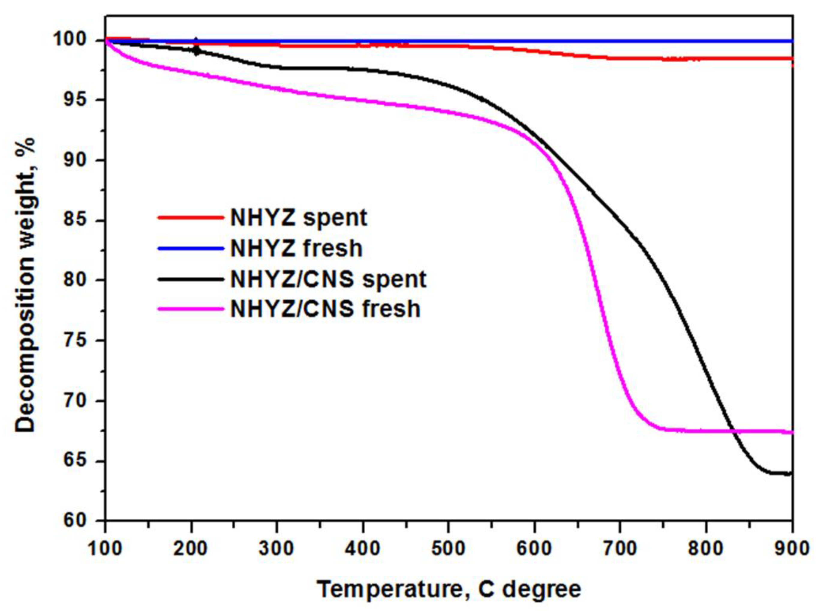
2.4. Catalytic Performance and Coke Formation
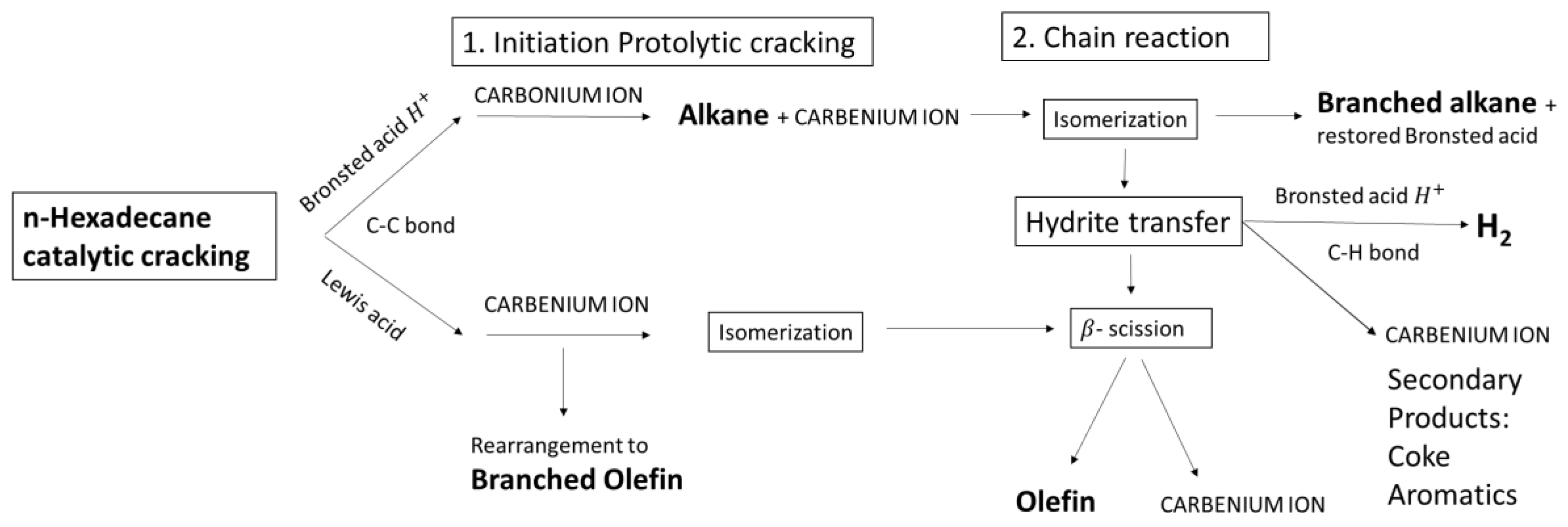
3. Discussion
4. Materials and Methods
4.1. Materials
4.2. Preparation of Composite Catalyst Using Ball Milling
4.3. Characterization
4.4. Catalytic Testing
5. Conclusions
Supplementary Materials
Author Contributions
Funding
Acknowledgments
Conflicts of Interest
References
- Holderich, W.; Hesse, M.; Näumann, F. Zeolites: Catalysts for organic syntheses. Angew. Chem. Int. Ed. 1988, 27, 226–246. [Google Scholar] [CrossRef]
- Schulz, H.F.; Weitkamp, J.H. Zeolite catalysts. Hydrocracking and hydroisomerization of n-dodecane. Ind. Eng. Chem. Prod. Res. Dev. 1972, 11, 46–53. [Google Scholar] [CrossRef]
- Anis, S.F.; Singaravel, G.; Hashaikeh, R. Electropsun Ni-W/zeolite composite fibers for n-heptane hydrocracking and hydroisomerization. Mater. Chem. Phys. 2017, 200, 146–154. [Google Scholar] [CrossRef]
- Fechete, I.; Wang, Y.; Védrine, J.C. The past, present and future of heterogeneous catalysis. Catal. Today 2012, 189, 2–27. [Google Scholar] [CrossRef]
- Zecevic, J.; Vanbutsele, G.; De Jong, K.P.; Martens, J.A. Nanoscale intimacy in bifunctional catalysts for selective conversion of hydrocarbons. Nature 2015, 528, 245–248. [Google Scholar] [CrossRef] [PubMed]
- Jasra, R.V.; Tyagi, B.; Badheka, Y.M.; Choudary, V.N.; Bhat, T.S. Effect of clay binder on sorption and catalytic properties of zeolite pellets. Ind. Eng. Chem. Res. 2003, 42, 3263–3272. [Google Scholar] [CrossRef]
- Wu, X.; Alkhawaldeh, A.; Anthony, R.G. Investigation on acidity of zeolites bound with silica and alumina. In Studies in Surface Science and Catalysis; Elsevier: Amsterdam, The Netherlands, 2000; pp. 217–225. [Google Scholar]
- Timken, H.K. Method for Preparing Titania-Bound Zeolite Catalysts. U.S. Patent 5,500,109, 4 July 1995. [Google Scholar]
- Chen, D.; He, L.; Shang, S. Study on aluminum phosphate binder and related Al2O3–SiC ceramic coating. Mater. Sci. Eng. A 2003, 348, 29–35. [Google Scholar] [CrossRef]
- Perego, C.; Bassi, G.; Girotti, G. Extruded Catalyst Based on Silica/Alumina Gel. U.S. Patent 20020099250A1, 4 November 2003. [Google Scholar]
- Bingre, R.; Louis, B.; Nguyen, P. An overview on zeolite shaping technology and solutions to overcome diffusion limitations. Catalysts 2018, 8, 163. [Google Scholar] [CrossRef]
- Wijngaarden, R.I.; Westerterp, K.R.; Kronberg, A.; Bos, A.N.R. Industrial Catalysis: Optimizing Catalysts and Processes; John Wiley & Sons: Hoboken, NJ, USA, 2008. [Google Scholar]
- Sun, H.; Shen, B.; Liu, J. N-Paraffins adsorption with 5A zeolites: The effect of binder on adsorption equilibria. Sep. Purif. Technol. 2008, 64, 135–139. [Google Scholar] [CrossRef]
- Chu, P.; Garwood, W.E. Catalytic Composition from Reaction of High Silica Zeolites with Binder. U.S. Patent 3308069A, 7 January 1986. [Google Scholar]
- Kauffman, J.W.; Hooks, P.A.; Nair, B.K.R. Method of Preparing an Alumina Catalyst Support and Catalyst for Dehydrogenation Reactions, and Its Use. U.S. Patent 9364815B2, 14 June 2016. [Google Scholar]
- Bartholomew, C.H. Mechanisms of catalyst deactivation. Appl. Catal. A Gen. 2001, 212, 17–60. [Google Scholar] [CrossRef]
- Anis, S.F.; Singaravel, G.; Hashaikeh, R. Hierarchical nano zeolite-Y hydrocracking composite fibers with highly efficient hydrocracking capability. RSC Adv. 2018, 8, 16703–16715. [Google Scholar] [CrossRef]
- Anis, S.F.; Hashaikeh, R. Electrochemical water splitting using nano-zeolite Y supported tungsten oxide electrocatalysts. J. Nanopart. Res. 2018, 20, 47. [Google Scholar] [CrossRef]
- Tosheva, L.; Valtchev, V.P. Nanozeolites: Synthesis, crystallization mechanism, and applications. Chem. Mater. 2005, 17, 2494–2513. [Google Scholar] [CrossRef]
- Van Steen, E.; Prinsloo, F.F. Comparison of preparation methods for carbon nanotubes supported iron Fischer–Tropsch catalysts. Catal. Today 2002, 71, 327–334. [Google Scholar] [CrossRef]
- Jiménez, V.; Sánchez, P.; Panagiotopoulou, P.; Valverde, J.L.; Romero, A. Methanation of CO, CO2 and selective methanation of CO, in mixtures of CO and CO2, over ruthenium carbon nanofibers catalysts. Appl. Catal. A Gen. 2010, 390, 35–44. [Google Scholar] [CrossRef]
- Coq, B.; Planeix, J.M.; Brotons, V. Fullerene-based materials as new support media in heterogeneous catalysis by metals. Appl. Catal. A Gen. 1998, 173, 175–183. [Google Scholar] [CrossRef]
- Zheng, M.; Pang, J.; Wang, A.; Zhang, T. One-pot catalytic conversion of cellulose to ethylene glycol and other chemicals: From fundamental discovery to potential commercialization. Chin. J. Catal. 2014, 35, 602–613. [Google Scholar] [CrossRef]
- Rodríguez-Reinoso, F. The role of carbon materials in heterogeneous catalysis. Carbon 1998, 36, 159–175. [Google Scholar] [CrossRef]
- Bradley, J.P.; Brownlee, D.E.; Fraundorf, P. Carbon compounds in interplanetary dust: Evidence for formation by heterogeneous catalysis. Science 1984, 223, 56–58. [Google Scholar] [CrossRef]
- Schrock, R.R. Multiple metal–carbon bonds for catalytic metathesis reactions (Nobel lecture). Angew. Chem. Int. Ed. 2006, 45, 3748–3759. [Google Scholar] [CrossRef] [PubMed]
- Yang, Y.; Chiang, K.; Burke, N. Porous carbon-supported catalysts for energy and environmental applications: A short review. Catal. Today 2011, 178, 197–205. [Google Scholar] [CrossRef]
- Zhang, J.; Liu, X.; Blume, R.; Zhang, A.; Schlögl, R.; Su, D.S. Surface-modified carbon nanotubes catalyze oxidative dehydrogenation of n-butane. Science 2008, 322, 73–77. [Google Scholar] [CrossRef] [PubMed]
- Zhang, Q.; Kang, J.; Wang, Y. Development of novel catalysts for Fischer–Tropsch synthesis: Tuning the product selectivity. ChemCatChem 2010, 2, 1030–1058. [Google Scholar] [CrossRef]
- Kong, H.; Zhou, M.; Lin, G.-D.; Hong-Bin, Z. Pt. catalyst supported on multi-walled carbon nanotubes for hydrogenation-dearomatization of toluene and tetralin. Catal. Lett. 2010, 135, 83–90. [Google Scholar] [CrossRef][Green Version]
- Shah, T.K.; Malecki, H.C.; Basantkumar, R.R.; Liu, H.; Fleischer, C.A.; Sedlak, J.J.; Patel, J.M.; Burgess, W.P.; Goldfinger, J.M. Carbon Nanostructures and Methods of Making the Same. U.S. Patent EP2900595A1, 26 September 2013. [Google Scholar]
- Mahmoud, L.; Lalia, B.S.; Hashaikeh, R. Carbon nanostructures modified LiFePO4 cathodes for lithium ion battery applications: Optimized porosity and composition. Mater. Res. Express 2016, 3, 125008. [Google Scholar] [CrossRef]
- Khalil, A.; Lalia, B.S.; Hashaikeh, R. Nickel oxide nanocrystals as a lithium-ion battery anode: Structure-performance relationship. J. Mater. Sci. 2016, 51, 6624–6638. [Google Scholar] [CrossRef]
- Zhuman, B.; Saepurahman; Anis, S.F.; Hashaikeh, R. Obtaining high crystalline ball milled HY zeolite particles with carbon nanostructures as a damping material. Microporous Mesoporous Mater. 2019, 273, 19–25. [Google Scholar] [CrossRef]
- Anis, S.F.; Lalia, B.S.; Hashaikeh, R.; Hilal, N. Breaking through the selectivity-permeability tradeoff using nano zeolite-Y for micellar enhanced ultrafiltration dye rejection application. Sep. Purif. Technol. 2020, 242, 116824. [Google Scholar] [CrossRef]
- Anis, S.F.; Hashaikeh, R.; Hilal, N. Flux and salt rejection enhancement of polyvinyl (alcohol) reverse osmosis membranes using nano-zeolite. Desalination 2019, 470, 114104. [Google Scholar] [CrossRef]
- Anis, S.F.; Hashaikeh, R. Electrospun zeolite-Y fibers: Fabrication and morphology analysis. Microporous Mesoporous Mater. 2016, 233, 78–86. [Google Scholar] [CrossRef]
- Brait, A.; Koopmans, A.; Weinstabl, H.; Ecker, A.; Seshan, K.; Lercher, J.A. Hexadecane conversion in the evaluation of commercial fluid catalytic cracking catalysts. Ind. Eng. Chem. Res. 1998, 37, 873–881. [Google Scholar] [CrossRef]
- Abbot, J.; Wojciechowski, B. Kinetics of catalytic cracking of n-paraffins on HY zeolite. J. Catal. 1987, 104, 80–85. [Google Scholar] [CrossRef]
- Plank, C.J. The Invention of Zeolite Cracking Catalysts—A Personal Viewpoint; ACS Publications: Washington, DC, USA, 1983. [Google Scholar]
- Srinivas, B.; Maity, S.; Prasad, V.; Rana, M.S.; Kumar, M.; Dhar, G.M.; Rao, T. Support effect studies on TiO2-Al2O3 mixed oxide hydroprocessing catalysts. In Studies in Surface Science and Catalysis; Elsevier: Amsterdam, The Netherlands, 1998; pp. 497–506. [Google Scholar]
- Ulfah, M.; Octavia, S.; Suherman, H.; Laniwati, M.; Makerthiharta, I.G.B.N. Synthesis and characterization of modified γ-Alumina-NaA and γ-Alumina-NaX zeolite composites as methanol dehydration catalysts in synthesis Dimethyl Ether (DME). In IOP Conference Series: Materials Science and Engineering; IOP Publishing: Kupang, Indonesia, 2020. [Google Scholar]
- Karami, D.; Mahinpey, N. Application of Novel Zeolite Y Nanoparticles in Catalytic Cracking Reactions. Chem. Eng. Commun. 2016, 203, 251–257. [Google Scholar] [CrossRef]
- Vuong, G.-T.; Hoang, V.-T.; Nguyen, D.-T.; Do, T.-O. Synthesis of nanozeolites and nanozeolite-based FCC catalysts, and their catalytic activity in gas oil cracking reaction. Appl. Catal. A Gen. 2010, 382, 231–239. [Google Scholar] [CrossRef]
- Bai, P.; Xie, M.; Etim, U.J.; Xing, W.; Wu, P.; Zhang, Y.; Liu, B.; Wang, Y.; Qiao, K.; Yan, Z. Zeolite Y mother liquor modified γ-Al2O3 with enhanced Brönsted acidity as active matrix to improve the performance of fluid catalytic cracking catalyst. Ind. Eng. Chem. Res. 2018, 57, 1389–1398. [Google Scholar] [CrossRef]
- Yin, H.; Zhou, T.; Liu, Y.; Chai, Y.; Liu, H. NiMo/Al2O3 catalyst containing nano-sized zeolite Y for deep hydrodesulfurization and hydrodenitrogenation of diesel. J. Nat. Gas Chem. 2011, 20, 441–448. [Google Scholar] [CrossRef]
- Hashaikeh, R. Insight into ball milling for size reduction and nanoparticles production of HY zeolite. Mater. Chem. Phys. 2018, 220, 322–330. [Google Scholar]
- John, T.M.; Wojciechowski, B.W. On identifying the primary and secondary products of the catalytic cracking of neutral distillates. J. Catal. 1975, 37, 240–250. [Google Scholar] [CrossRef]
- Swisher, J.A.; Hansen, N.; Maesen, T.; Keil, F.J.; Smit, B.; Bell, A.T. Theoretical simulation of n-alkane cracking on zeolites. J. Phys. Chem. C 2010, 114, 10229–10239. [Google Scholar] [CrossRef]
- Corma, A.; Planelles, J.; Sánchez-Marín, J.; Tomás, F. The role of different types of acid site in the cracking of alkanes on zeolite catalysts. J. Catal. 1985, 93, 30–37. [Google Scholar] [CrossRef]
- Guisnet, M.; Gilson, J.-P. Zeolites for Cleaner Technologies; World Scientific: Singapore, 2002; Volume 3. [Google Scholar]
- Planelles, J.; Sanchez-Marin, J.; Tomas, F.; Corma, A. On the formation of methane and hydrogen during cracking of alkanes. J. Mol. Catal. 1985, 32, 365–375. [Google Scholar] [CrossRef]
- Commeyras, A.; Olah, G.A. Chemistry in super acids. II. Nuclear magnetic resonance and laser Raman spectroscopic study of the antimony pentafluoride-fluorosulfuric acid (sulfur dioxide) solvent system (magic acid). The effect of added halides, water, alcohols, and carboxylic acids. Study of the hydronium ion. J. Am. Chem. Soc. 1969, 91, 2929–2942. [Google Scholar]
- Olah, G.A.; DeMember, J.R.; Shen, J. Electrophilic reactions at single bonds. X. Hydrogen transfer, alkylation, and alkylolysis of alkanes with methyl and ethyl fluoroantimonate. J. Am. Chem. Soc. 1973, 95, 4952–4956. [Google Scholar] [CrossRef]
- Abbot, J.; Wojciechowski, B. The mechanism of paraffin reactions on HY zeolite. J. Catal. 1989, 115, 1–15. [Google Scholar] [CrossRef]


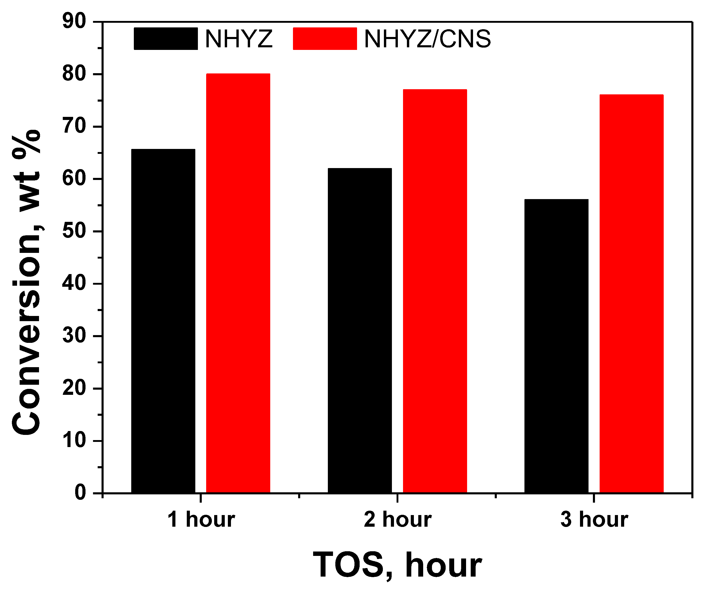
| Catalyst Name | NHYZ | NHYZ/CNS |
|---|---|---|
| Hours | Conversion % | |
| 1 | 66 | 80 |
| 2 | 62 | 77 |
| 3 | 56 | 76 |
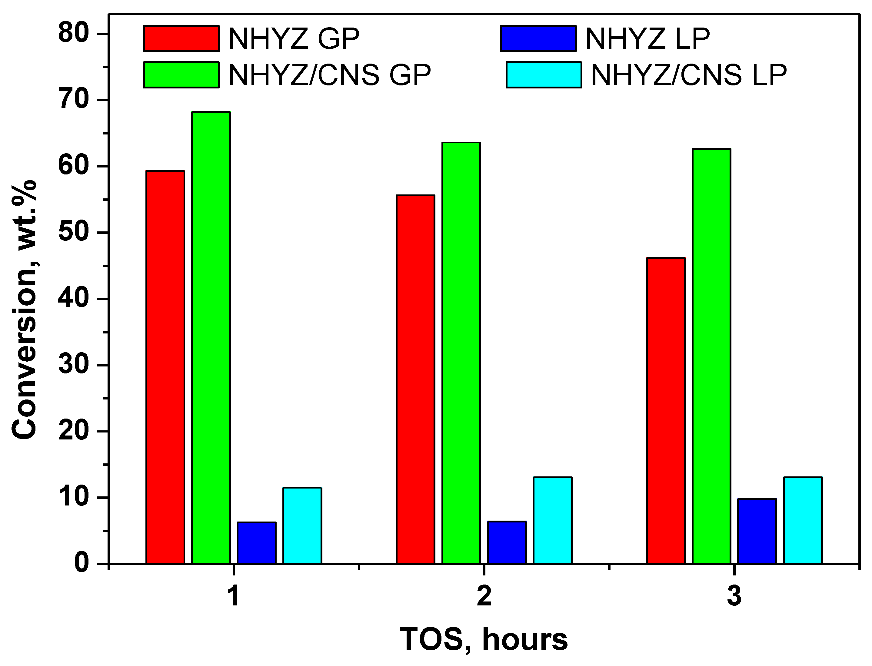
| TOS | Gaseous Products (GP), wt.% | Liquid Products (LP), wt.% | Coke after 3 h TOS, wt.% |
|---|---|---|---|
| NHYZ | |||
| 1 | 59.3 | 6.3 | 0.8 |
| 2 | 55.6 | 6.4 | |
| 3 | 46.2 | 9.8 | |
| NHYZ/CNS | |||
| 1 | 68.2 | 11.5 | 3.4 |
| 2 | 63.6 | 13.1 | |
| 3 | 62.6 | 13.1 | |
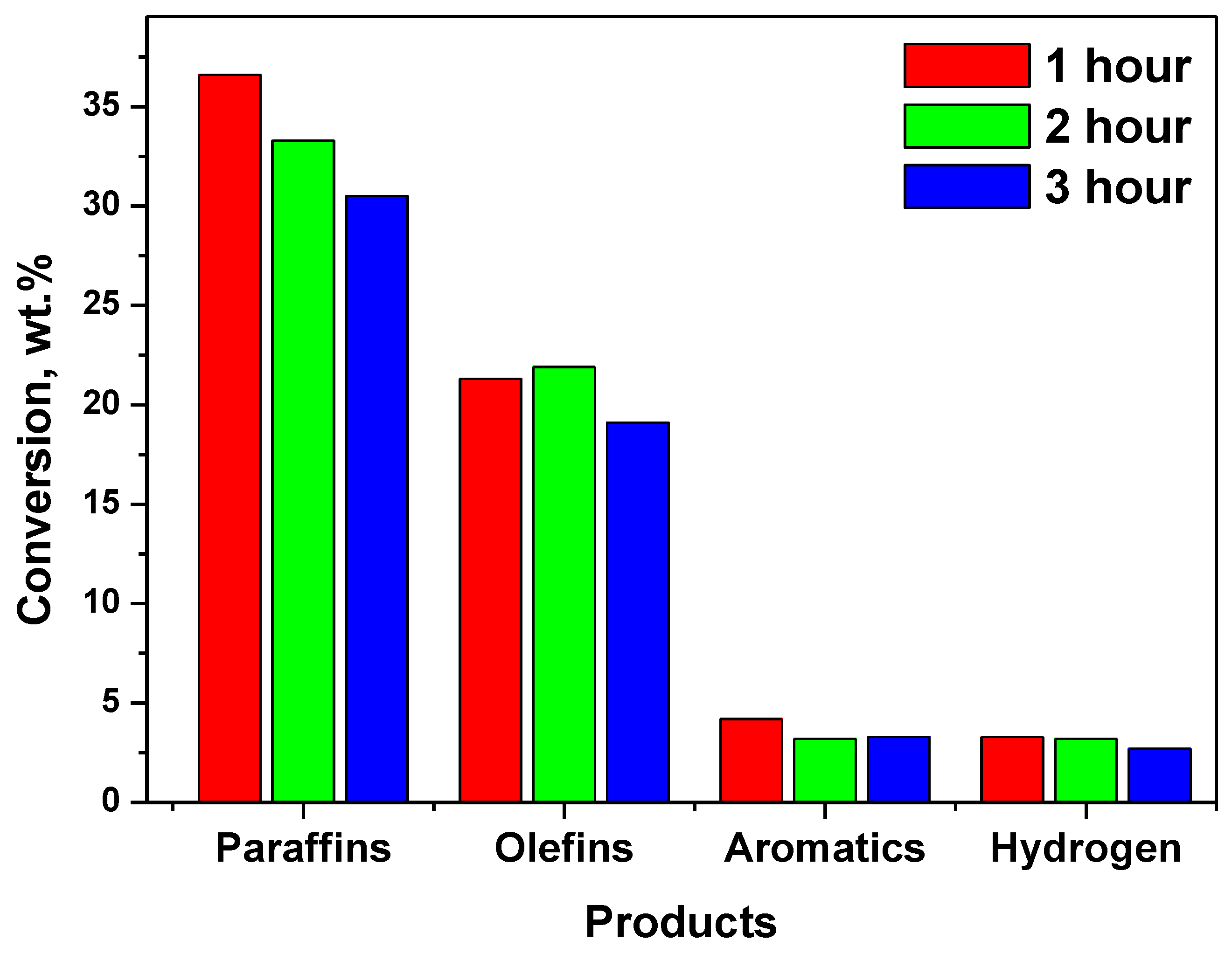
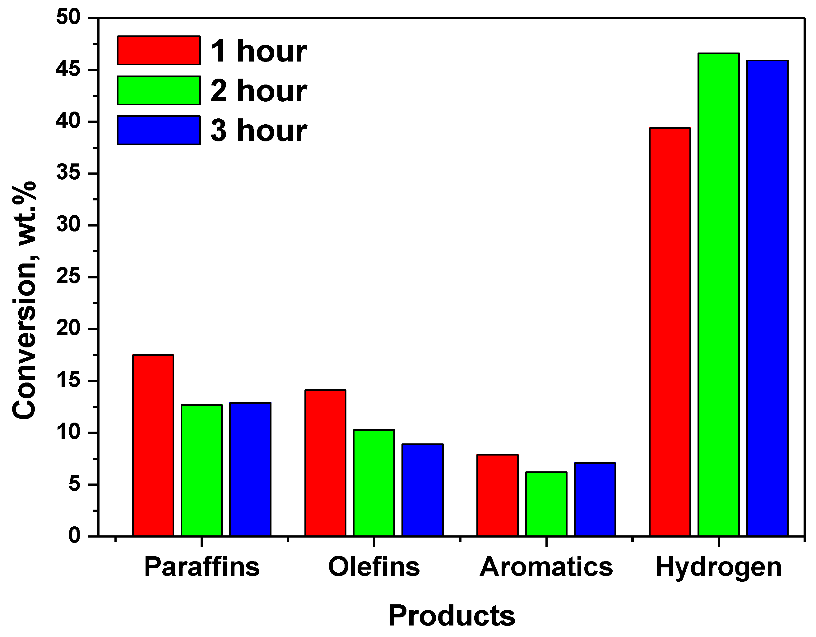
| Catalyst | NHYZ | NHYZ/CNS | ||||
|---|---|---|---|---|---|---|
| TOS | 1 | 2 | 3 | 1 | 2 | 3 |
| Paraffins | 36.6 | 33.3 | 30.5 | 17.5 | 12.7 | 12.9 |
| Olefins | 21.3 | 21.9 | 19.1 | 14.1 | 10.3 | 8.9 |
| Aromatics | 4.2 | 3.2 | 3.3 | 7.9 | 6.2 | 7.1 |
| Hydrogen | 3.3 | 3.2 | 2.7 | 39.4 | 46.6 | 45.9 |
| No | FCC Catalyst | Surface Area, m2/g | Reference |
|---|---|---|---|
| 1 | Nano-Y zeolite in SiO2/Al2O3 matrix | 230 | [43] |
| 2 | Nano-zeolite-Y in SiO2 binder | 315 (nano-zeolite-Y original surface area 570) | [44] |
| 3 | Micro-zeolite-Y-supported Al2O3 | 341 (zeolite-Y original surface area 672) | [45] |
Publisher’s Note: MDPI stays neutral with regard to jurisdictional claims in published maps and institutional affiliations. |
© 2020 by the authors. Licensee MDPI, Basel, Switzerland. This article is an open access article distributed under the terms and conditions of the Creative Commons Attribution (CC BY) license (http://creativecommons.org/licenses/by/4.0/).
Share and Cite
Zhuman, B.; Anis, S.F.; Saepurahman; Singravel, G.; Hashaikeh, R. Catalytic Cracking of n-Hexadecane Using Carbon Nanostructures/Nano-Zeolite-Y Composite Catalyst. Catalysts 2020, 10, 1385. https://doi.org/10.3390/catal10121385
Zhuman B, Anis SF, Saepurahman, Singravel G, Hashaikeh R. Catalytic Cracking of n-Hexadecane Using Carbon Nanostructures/Nano-Zeolite-Y Composite Catalyst. Catalysts. 2020; 10(12):1385. https://doi.org/10.3390/catal10121385
Chicago/Turabian StyleZhuman, Botagoz, Shaheen Fatima Anis, Saepurahman, Gnanapragasam Singravel, and Raed Hashaikeh. 2020. "Catalytic Cracking of n-Hexadecane Using Carbon Nanostructures/Nano-Zeolite-Y Composite Catalyst" Catalysts 10, no. 12: 1385. https://doi.org/10.3390/catal10121385
APA StyleZhuman, B., Anis, S. F., Saepurahman, Singravel, G., & Hashaikeh, R. (2020). Catalytic Cracking of n-Hexadecane Using Carbon Nanostructures/Nano-Zeolite-Y Composite Catalyst. Catalysts, 10(12), 1385. https://doi.org/10.3390/catal10121385