Article

Inter-Vehicle Communication Protocol Design for a Yielding Decision at an Unsignalized Intersection and Evaluation of the Protocol Using Radio Control Cars Equipped with Raspberry Pi

Information Systems Science Major, Graduate School of Engineering, Soka University, 1-236 Tangi-cho, Hachioji-shi 192-8577, Japan
*
Author to whom correspondence should be addressed.
Computers 2019, 8(1), 16; https://doi.org/10.3390/computers8010016
Submission received: 22 December 2018 / Revised: 11 February 2019 / Accepted: 14 February 2019 / Published: 18 February 2019

Abstract

:
The Japanese government aims to introduce self-driven vehicles by 2020 to reduce the number of accidents and traffic jams. Various methods have been proposed for traffic control at accident-prone intersections to achieve safe and efficient self-driving. Most of them require roadside units to identify and control vehicles. However, it is difficult to install roadside units at all intersections. This paper proposes an inter-vehicle communication protocol that enables vehicles to transmit their vehicle information and moving direction information to nearby vehicles. Vehicles identify nearby vehicles using images captured by vehicle-mounted cameras. These arrangements make it possible for vehicles to exchange yielding intention at an unsignalized intersection without using a roadside unit. To evaluate the operations of the proposed protocol, we implemented the protocol in Raspberry Pi computers, which were connected to cameras and mounted on radio control cars and conducted experiments. The experiments simulated an unsignalized intersection where both self-driven and human-driven vehicles were present. The vehicle that had sent a yielding request identified the yielding vehicle by recognizing the colour of each radio control car, which was part of the vehicle information, from the image captured by its camera. We measured a series of time needed to complete the yielding sequence and evaluated the validity of yielding decisions.

1. Introduction

With a view to making road traffic in Japan the safest in the world, the Japanese government aims to introduce conditional self-driving, in which cars are driven automatically except where continuous self-driving is difficult, by 2020 and vehicles with advanced self-driving capability, which can appropriately handle driving even where continuous self-driving is difficult, by 2025 [1]. While the introduction of self-driving systems is expected to reduce the number of accidents and traffic jams, it is necessary to implement new vehicle running control regulations and invest in roadside infrastructures if we are to ensure safe and efficient traffic on the road. Many researchers have proposed traffic control methods, in particular for application to accident-prone intersections [2,3,4,5,6,7]. Generally, it is difficult for vehicles to recognize other vehicles and exchange information with them autonomously. The most common method of recognizing surrounding cars at an intersection is to use a roadside unit. However, it is difficult to install roadside units at all intersections, including those that have no traffic lights.
This paper proposes an inter-vehicle communication protocol that enables vehicles to decide to yield autonomously without relying on a roadside unit. A vehicle at an unsignalized intersection recognizes the intersection conditions, including information about the surrounding vehicles and the road shapes, using a vehicle-mounted camera and conducts peer-to-peer (P2P) communication with the identified vehicle. We implemented the proposed protocol in Raspberry Pi computers, which were mounted on radio control cars and conducted experiments to evaluate the effectiveness of the protocol. In addition, considering a transitional period in which there is a mix of self-driven and human-driven vehicles on roads, we implemented a user interface through which the driver in a human-driven vehicle can communicate with a self-driven vehicle using the proposed protocol. Section 2 reviews related studies and indicates how the present research fits in the picture. Section 3 details the proposed yielding method and protocol. Section 4 presents an experimental system we developed to verify the operations of the proposed protocol. Section 5 describes the evaluation method used and the results of the experiments. Section 6 summarizes this paper and presents future issues.

2. Related Studies

There are several studies on controlling vehicles at an intersection. The method proposed in Reference [2] assumes only self-driven vehicles and combines optimization of traffic signal change timing and optimization of vehicle speeds at a signalized intersection. The system exchanges information with a roadside unit and estimates the times when vehicles arrive at the intersection. It adjusts the time when the traffic light changes and also controls vehicle speeds based on their estimated arrival times so that the vehicles can go through the intersection without stopping.
The method proposed in Reference [3] assumes only human-driven vehicles at a T-shaped intersection where a low-priority road meets a priority road. If the distance between the two vehicles concerned is greater than a certain value, the method ensures safe driving by allowing the vehicle on the low-priority road to go into the priority road after a yielding request and consent process.
In Reference [4], self-driven vehicles exchange information with the roadside unit at an unsignalized intersection to estimate their times of arrival at the intersection and generate their intersection passing schedules. The vehicles adjust their speeds based on the schedules so that they can go through the intersection nonstop.
The study in Reference [5] extends a method called “autonomous intersection management (AIM),” in which self-driven vehicles coming to an unsignalized intersection communicate with the roadside unit to reserve the orders in which they are allowed to go through the intersection and the roadside unit manages the vehicles. This method improves the overall traffic flow by selecting the routes of individual vehicles based on their total running time, which is estimated by the AIM systems at a number of intersections working together.
The method proposed in Reference [6] addresses human-driven vehicles that have inter-vehicle communication capability. When a vehicle approaches an unsignalized intersection, the system estimates the time when the vehicle arrives at the intersection from its speed and distance to the intersection and displays a virtual traffic light within the vehicle. This method enhances traffic safety because virtual traffic lights are displayed even at unsignalized intersections. However, it does not consider cases where cars are waiting on two or more roads going in different directions. The method in Reference [7] is an improvement over this in that it considers waiting time and can handle cases where cars are waiting on multiple roads. It thus further enhances traffic safety.
Except for the methods proposed in Reference [3,6,7], all methods use roadside units to control traffic and thus cannot be applied to all intersections. The method in Reference [3] addresses only T-shaped intersections and does not describe how vehicles recognize each other and communicate with each other. While the methods in Reference [6,7] do not require roadside units, they are designed to support human drivers and do not consider cases where both self-driven and human-driven vehicles are present. In contrast, the present paper proposes a protocol that can be applied to an unsignalized intersection and a situation in which there is a mix of self-driven and human-driven vehicles. Vehicles use P2P communication to negotiate about whether to yield. Table 1 compares the various traffic control methods mentioned above and the method proposed in the present paper.

3. Yielding Method at an Unsignalized Intersection

This section describes how vehicles at an unsignalized intersection decide to yield by exchanging messages and presents the state transition diagram for yielding control. It also identifies various yielding patterns and presents the design of the inter-vehicle communication protocol used for yielding control.

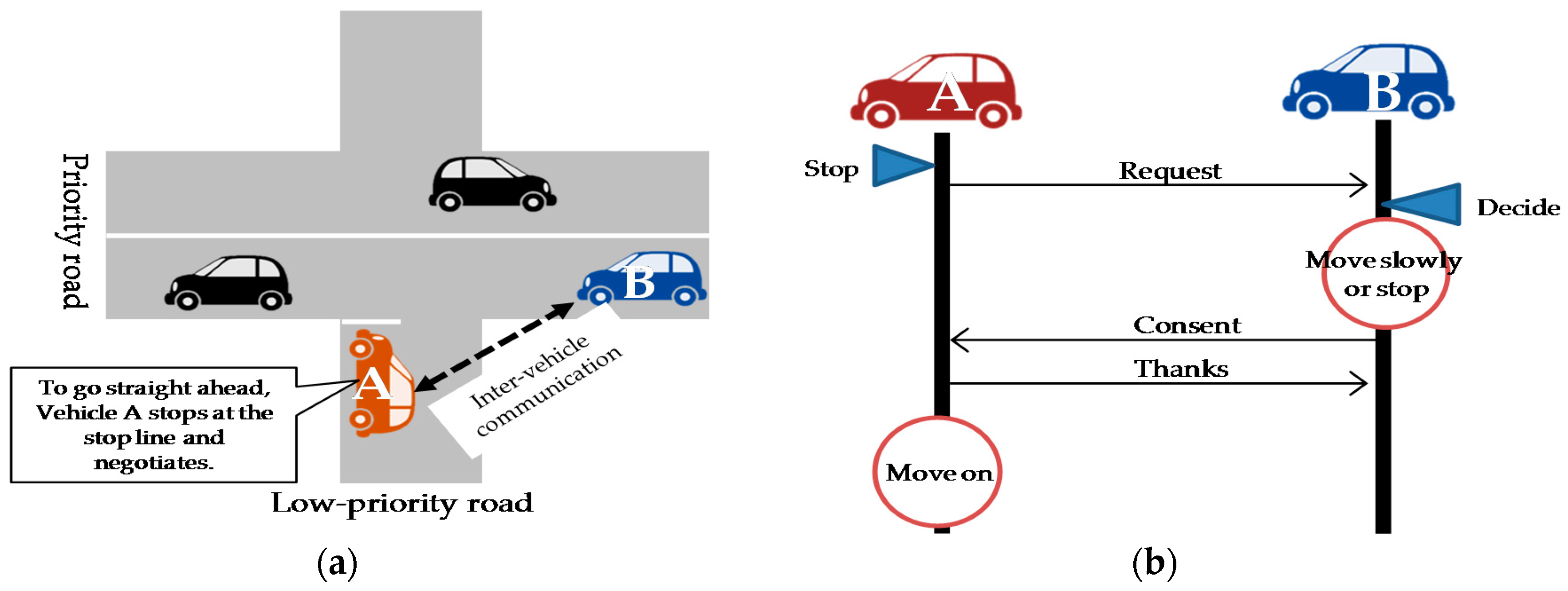
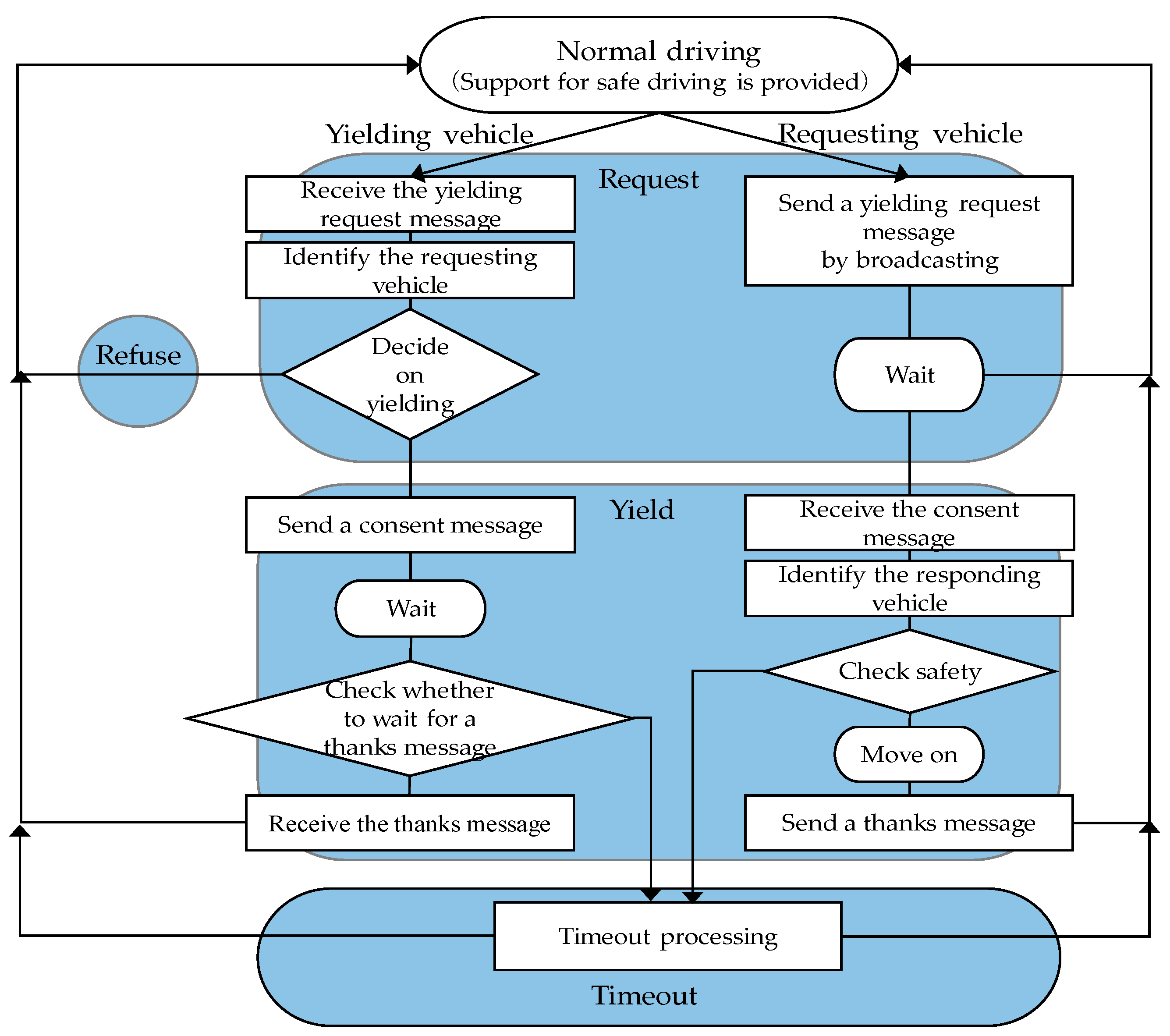
3.1. Yielding Based on Message Exchanges and the Related State Transition Diagram

The proposed system assumes that every vehicle has an inter-vehicle communication terminal, a camera that can capture images of all directions and a Global Positioning System (GPS) device. It is applied to an unsignalized intersection that is somewhat congested due to different priorities assigned to different roads. Figure 1 shows an example situation in which a vehicle yields to another vehicle at an intersection by exchanging messages. Vehicle A on the low-priority road wants to cross the priority road and go straight ahead. When it arrives at the intersection, it broadcasts a yielding request message. Vehicle B receives the request message, identifies the requesting vehicle, determines from its speed (which is obtained from the Controlled Area Network (CAN)) and surrounding conditions whether it can safely yield. Depending on its decision, it sends back a consent message or a refusal message via P2P communication. When Vehicle A receives a consent message, it knows that it can go into the intersection and does so cautiously. If the vehicle does not move within a certain period because, for example, it determines that the presence of pedestrians prevents it from running safely, the timeout process works and cancels this yielding. If the yielding is successful, the requesting vehicle sends a thanks message to the yielding vehicle and the two vehicles return to the normal driving state. If the requesting vehicle receives no response to its yielding request message within a certain period, it resends a yielding request message if there is a vehicle on the priority road or moves on if there is no vehicle on the priority road and it can run safely. The state transition diagram for the series of steps for yielding decision is shown in Figure 2.

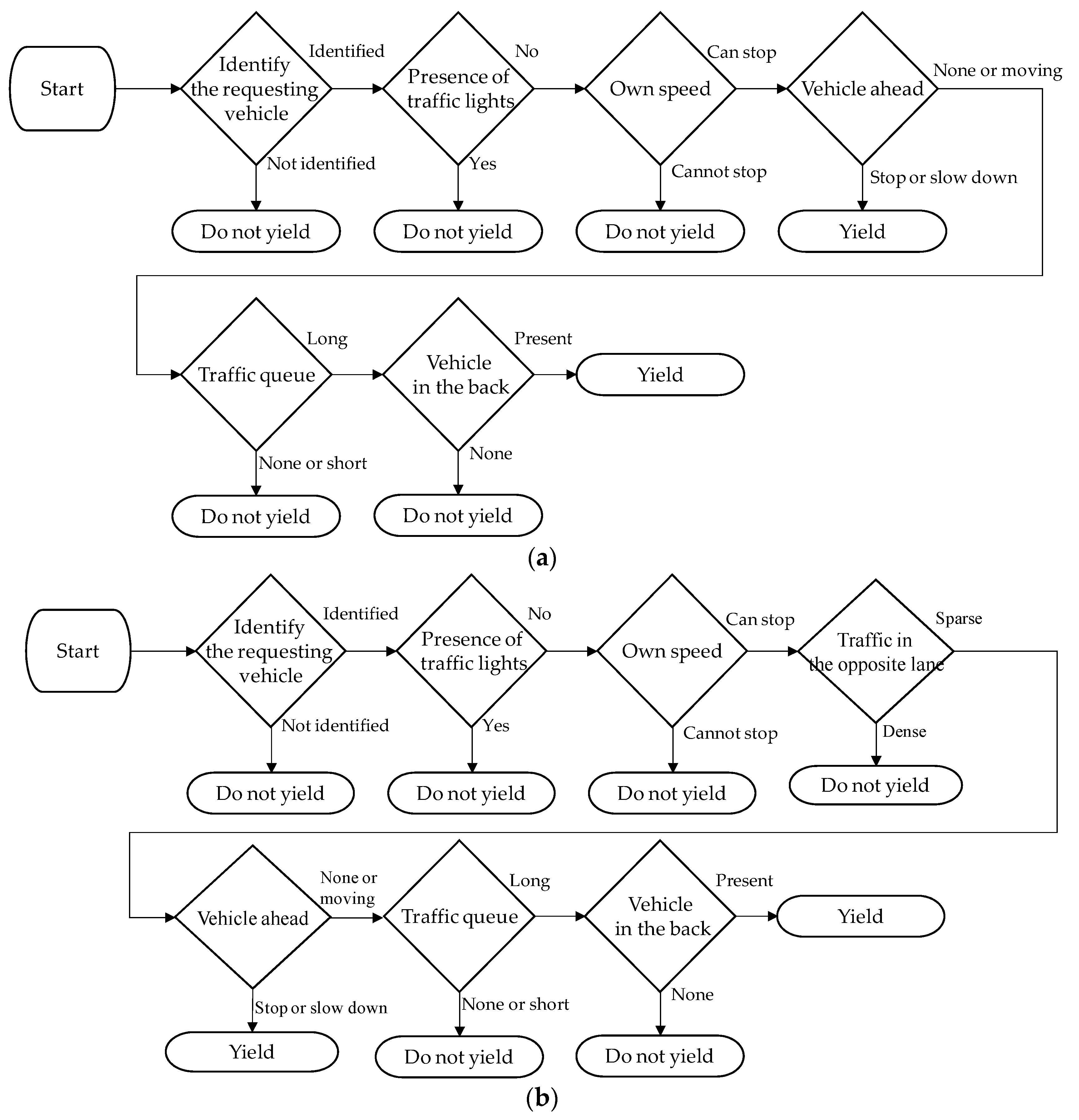
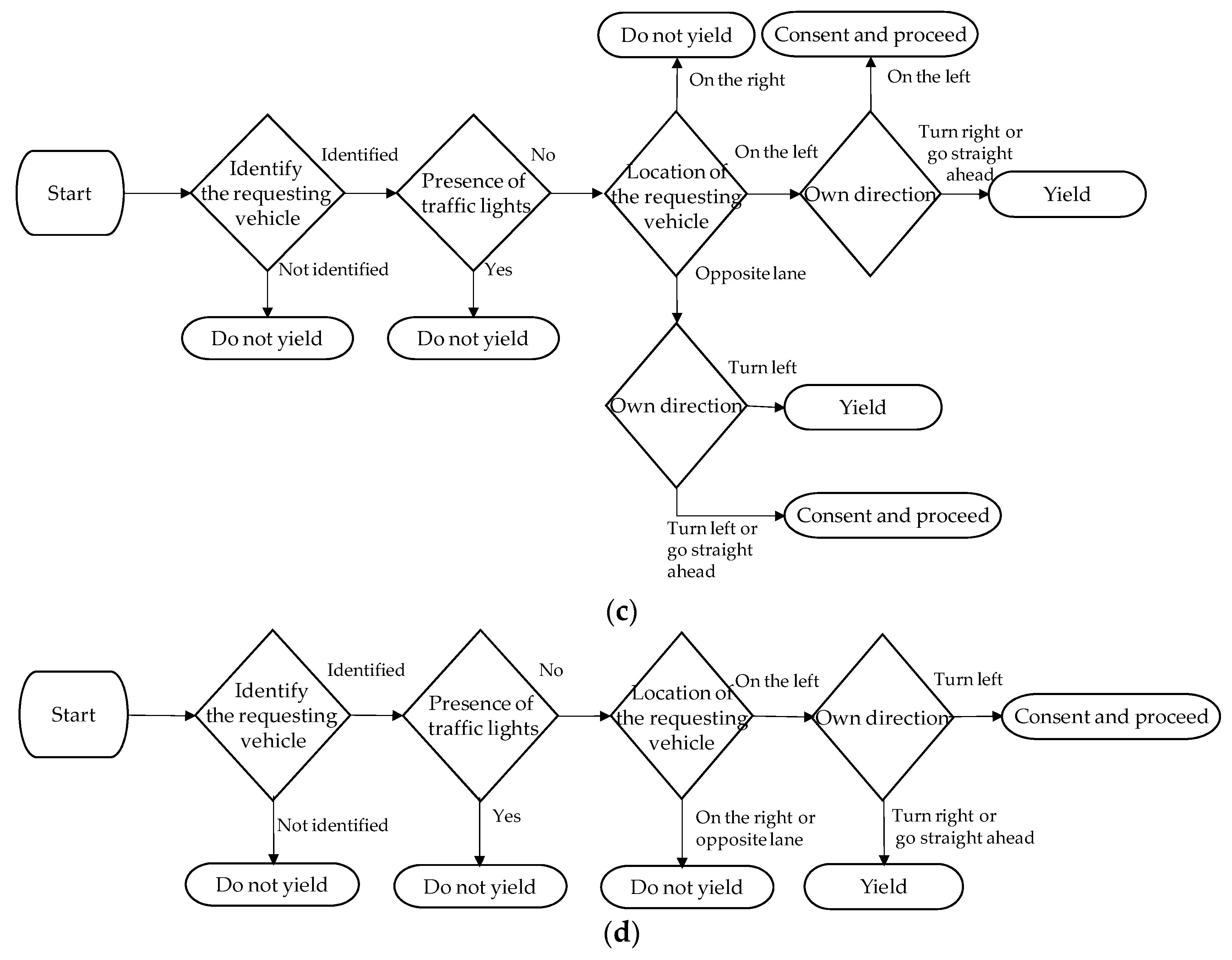
3.2. Yielding Patterns

A number of yielding patterns can be identified based on the state transition diagram shown in Figure 2. They can be classified according to the road widths, moving direction and the way the vehicles involved find each other. In Japan, the priorities of roads at an unsignalized intersection are determined based on the differences in the road widths, the road signs or road surface markings in accordance with the road traffic law. Traffic is controlled based on the determined priorities but vehicles on a low-priority road may find it difficult to go into the intersection if the volume of traffic is large or the inter-vehicle spacing is small on the priority road.
For example, at an intersection where a residential road meets a wider road that has a high volume of traffic, it is often the case that only a stop sign exists with no traffic lights because the difference in the volume of traffic makes it clear which road has priority. When a vehicle on a low-priority road wants to go into a priority road, it needs to choose the right timing so that it will not obstruct the traffic on the priority road. However, during the time of day when there is heavy traffic or where a signalized intersection is nearby, there are rarely opportunities for a vehicle on the low priority road to go into the priority road safely. So, it cannot go into the priority road unless a vehicle on the priority road yields the right of way.
When a vehicle on the priority road wants to turn right into a low-priority residential road, it needs to cross the opposite lane and thus needs to choose the right time so that it will not hinder the traffic in the opposite lane. Often, there is no right-turn-only lane. In such a case, the vehicle may hinder the traffic in the back unless a vehicle in the opposite lane yields the right of way.
If all the roads that meet at an intersection are narrow, priority cannot be assigned to any of them. At such an intersection, the vehicle on the left has the right of way. This principle clarifies which vehicle is to proceed first and eliminates any confusion. In such a case, drivers customarily indicate their intentions to yield by a hand signal.
Based on their driving experiences, the authors selected six situations in which yielding can occur at an unsignalized intersection, taking into consideration the situations in which the road traffic law gives a low priority to certain types of road. These are shown in Table 2. The lanes are drawn in accordance with the Japanese traffic rules (traffic keeps to left). Any situations not covered by these patterns are out of scope of the proposed system.
Patterns 1, 2 and 3 in Table 2 concern a vehicle on a low-priority road at an interaction where roads with different priorities meet. Also, these patterns involve a vehicle on a low-priority road trying to go to a priority road. These can cover cases where a vehicle tries to go out of the exit of some facility. Pattern 4 applies to a vehicle on the priority road that wants to turn right into a low-priority road at an intersection similar to that to which Patterns 1, 2 and 3 are applied. Patterns 5 and 6 apply to a vehicle at an intersection where there is no distinction of priority between the two crossing roads.
The criteria by which a vehicle decides whether to yield the right of way are based on these patterns. A vehicle’s decision on whether to yield depends on a number of factors: the presence or absence of a traffic light, its speed, the condition of the vehicle ahead, the length of the traffic queue, if any, presence or absence of a vehicle in the back, the condition of the opposite lane, the location of the requesting vehicle and the lane into which it wants to proceed. These items are taken into consideration not because a vehicle should always yield but because a vehicle should yield only when yielding improves traffic flow.
Figure 3 shows yielding decision flowcharts for the six yielding patterns. They are based on the logic described in Figure 2.
The decision flowcharts for Patterns 1 and 4 are the same. A vehicle that has received a yielding request (hereafter referred to as “the responding vehicle”) decides as follows. If the responding vehicle identifies the requesting vehicle and finds that the intersection has no traffic lights, it checks whether it is running slow enough to be able to stop. If it is slow enough, it checks whether the vehicle ahead is likely to stop. If the vehicle ahead is likely to stop, the responding vehicle needs to stop and yields the right of way. If the vehicle ahead is not slowing down, the responding vehicle checks the queue in the lane of the requesting vehicle. If the queue is long, it checks whether there is a vehicle in the back. If there is a vehicle in the back, the responding vehicle yields. If there is no vehicle in the back, the responding vehicle does not yield because the requesting vehicle can proceed after the responding vehicle has passed by.
The decision flowcharts for Patterns 2 and 3 are identical. It differs from the flowchart for Patterns 1 and 4 in that the responding vehicle additionally checks the condition of the opposite lane before it checks the vehicle ahead. If the traffic in the opposite lane is dense, the requesting vehicle cannot go into the lane even if the responding vehicle yields. Therefore, the responding vehicle does not yield. If the traffic in the opposite lane is sparse, the responding vehicle moves on to check the vehicle ahead.
The decision flowchart for Pattern 5 is as follows. If the responding vehicle identifies the requesting vehicle and finds that the intersection has no traffic lights, it checks the location of the requesting vehicle. If the requesting vehicle is on the right, the responding vehicle does not yield because the vehicle on the left has the right of way. If the requesting vehicle is on the left, the responding vehicle yields. If the responding vehicle is to turn left, the paths of the two vehicles do not cross. Therefore, the responding vehicle sends a consent message but does not stop. If the requesting vehicle is in the opposite lane and the responding vehicle is to turn right, it yields. Otherwise, the paths of the two vehicles do not cross. Therefore, the responding vehicle sends a consent message but does not stop.
The decision flowchart for Pattern 6 is as follows. If the responding vehicle identifies the requesting vehicle and finds that the intersection has no traffic lights, it checks the location of the requesting vehicle. If the requesting vehicle is either on the right or in the opposite lane, the responding vehicle does not yield. If the requesting vehicle is on the left, the responding vehicle yields. If the responding vehicle is to turn left, the paths of the two vehicles do not cross. Therefore, the responding vehicle sends a consent message but does not stop.

3.3. Design of the Inter-Vehicle Communication Protocol Used for Yielding Control

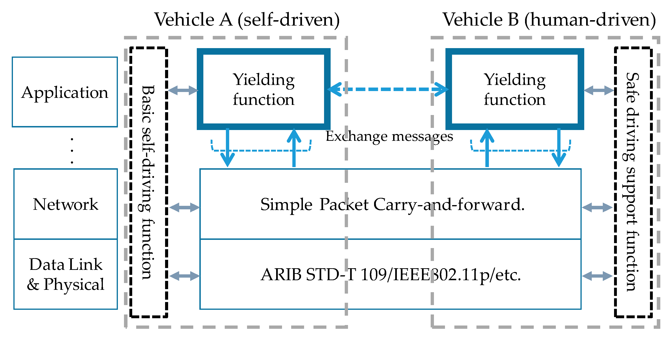
3.3.1. Assumed Inter-Vehicle Communication Protocol Stack

It is assumed that self-driven vehicles have all the basic self-driving functions, including a function to prevent a rear-end collision and that human-driven vehicles have a driving support function designed to ensure high safety. The yielding function is considered to be an additional function for both self-driven and human-driven vehicles. Vehicles exchange messages via inter-vehicle communication. The standard means of inter-vehicle communication adopted in the U.S. and Europe is IEEE 802.11p [8], which operates at the 5.9 GHz band. Japan uses Dedicated Short-Range Communications (DSRC) [9], one of the ITS systems operating at the 5.8 GHz band, for its Electronic Toll Collection (ETC) system. To avoid interference with this system, ARIB STD-T 109 [10], which uses the 700 MHz band, is being studied for use as the standard means of inter-vehicle communication. Since the standardization of the lower layers is in progress as described above, the proposed yielding function is to be implemented at the application layer in the assumed inter-vehicle communication protocol stack, as shown in Figure 4.

3.3.2. Message Elements and Format

ARIB STD-T 109 defines the format of application layer messages. It provides for a 60-byte free data field that can be used by applications [11]. Therefore, we have defined a dedicated message format shown in Table 3 for the inter-vehicle communication protocol. Any message is put in this free data field.
A message consists of the following fields: system ID, message length, destination information, sender information, yielding pattern number, requester confirmation bit and message type.
1. Definition of yielding-related messages
The length of the system ID is fixed to 4 bytes (0x01595257). “0x01” is a control character in the ASCII code and indicates the beginning of a header. “0x595257” is an ASCII code for “YRM,” which stands for Yield the Right of Way. When a received message has this ID, it is identified as a yielding-related message.
The message length indicates the byte length of a yielding-related message. One byte is assigned to it. The maximum message length is 32 bytes so that a message can fit into a 60-byte free area. No message longer than that is exchanged.
2. Identification of the destination vehicle
Destination information is a 4-byte ID assigned to each vehicle. The serial number of the communication terminal mounted on each vehicle is used as a vehicle ID. Since this ID field has 4 bytes, there can be 4,294,967,296 different vehicles, which is numerous enough to avoid duplication. In inter-vehicle communication, most messages are broadcast. A vehicle that has received a message accepts it if the message’s destination ID is either the broadcast ID (0xffffffff) or its vehicle ID in P2P communication.
3. Identification of the sender vehicle based on vehicle information
Since GPS-based detection of the locations of vehicles relatively close to each other near an intersection depends on the accuracy of GPS, we decided to use visual vehicle detection from images taken by a camera in combination with GPS. Since vehicles do not run at the same speed and GPS has some error, the relative locations of vehicles running close to each other may be identified incorrectly if the identification depends on GPS information only. This may result in yielding actions taking place even when the vehicles involved are not communicating correctly. Suppose that two vehicles on a priority road are approaching an intersection and only the vehicle in the back has agreed to yield. If the vehicle in the front is running slow enough to stop at the intersection and if the requesting car on a low-priority road recognizes the relative locations of the two cars incorrectly, it may erroneously identify the car in the front as the yielding car and go into the intersection. This may lead to the car on the priority road making a hard stop. If it is a human-driven car, the driver may brake too late, resulting in an accident. To avoid this situation, we use both GPS-based identification and visual vehicle detection from images taken by a camera. Specific vehicle information and message exchanges used are as follows.
The sender information consists of a 4-byte vehicle ID, 3-byte vehicle information (one byte for the vehicle maker, one byte for the vehicle model and one byte for the vehicle colour) and 8-byte location information. The total length is 15 bytes. A vehicle broadcasts a yielding request message with no destination specified. Therefore, it can notify surrounding vehicles of its ID. A vehicle that has received a yielding request message can identify the requesting vehicle by referring to the sender ID in the received message and sends a consent message or a refusal message via P2P communication. If detailed information about the maker, vehicle model and vehicle colour should be included in a message, the message length becomes long. To avoid this, only three bytes are used to indicate the maker number, the model number and the colour number. Detailed vehicle information is stored in the vehicle information database of the yielding system. A vehicle that has received a message can get detailed vehicle information of the message sender by accessing this database using the 3-byte vehicle information in the message. When a vehicle has received a yielding request message or a consent message, it identifies the vehicle of the message sender based on this vehicle information together with the location information. If a number of vehicles with the same maker, the same model and the same colour are present at more or less the same spot, it is not possible to identify a specific vehicle by this information. In such a case, the vehicle of the message sender is identified using motion tracking, which provides information about whether a vehicle is in the process of stopping to yield to another vehicle. If this does not work, it is determined that it is not possible to identify the vehicle and the yielding process, which after all is not absolutely required, is cancelled.
4. Yielding processing and exception processing
Four bits are assigned to the yielding pattern, which ranges from 1 to 6 or from 0001 to 0110 in binary. Although three bits are sufficient, four bits are assigned to allow for a possible increase in the number of patterns in the future.
The requester confirmation bit indicates whether the message sender is a yielding requesting vehicle or a responding vehicle. “0” indicates the responding side and “1” the requesting side. When a vehicle receives a message, this bit controls the way the system works.
The 3-bit message type indicates the following. “000” indicates a request for turning left, “001” a request for turning right, “010” a request for going straight ahead, “011” consent, “100” refusal, “101” thanks, “110” timeout and “111” cancellation. The spare bits in the message body is normally not used (0 byte). They are used only in Patterns 2, 3, 5 and 6 to notify that, at the time of sending a consent message, there is no oncoming vehicle (expressed by 0x01). A timeout message is sent by the yielding vehicle when the requesting vehicle takes no action within a certain period. When the requesting vehicle receives this message, it returns the same timeout message so that the yielding process will be terminated. When the requesting vehicle receives a consent message, it broadcasts a cancellation message. The vehicle that has sent the consent message ignores this cancellation message. When a vehicle that has received a request message but has not replied to it because it has taken a long time to make a decision or for some other reason receives this cancellation message, it understands that the yielding request has been cancelled (which may imply that another vehicle has yielded). When a vehicle that has not received a request message receives a cancellation message, it does nothing. It only knows that a yielding action has been taken elsewhere.
As an example, the message sequence in Pattern 3 in the situation shown in Figure 5 is illustrated in Figure 6 and Table 4. The symbols of message elements correspond to the symbols in Table 3.
The above example shows Pattern 3. Vehicle A broadcasts a request for going straight ahead (message m1) to the surrounding vehicles. Vehicle B is approaching the intersection from the right side. It receives the request message and identifies Vehicle A using the sender vehicle information (h5, 6, 7) in the message and returns a consent message (message m3). Vehicle A receives the consent message, identifies Vehicle B using the sender vehicle information (h5, 6, 7) in the message and recognizes the relative positions of itself and Vehicle B from the location of Vehicle B in the image captured by the vehicle-mounted camera. Vehicle C returns a refusal message (message m2) possibly because it was not able to identify Vehicle A (possibly because it has already passed the intersection). Although Vehicle A has not received consent from the vehicle on the left, it knows that Vehicle B does not see any oncoming vehicle (which means for Vehicle A that no vehicle is coming from the left side) from the spare information (b4) in message m3. This means that Vehicle A can go straight ahead. Vehicle B, which has consented to yield, slows down (or stops). After this, the yielding process may succeed or not depending on whether Vehicle A can confirm safety. If Vehicle A confirms that it can cross the road safely, it proceeds to the intersection.
Figure 6a shows an example in which yielding is successful. Vehicle C has already passed the intersection. Since Vehicle B has consented to yield, Vehicle A confirms that it is safe to move, starts to go into the intersection and sends a thanks message (message m4) to Vehicle B. This completes the entire yielding procedure.
Figure 6b shows an example in which yielding has failed. Since Vehicle A cannot confirm safety possibly because there is a pedestrian, it cannot start within a certain period. In such a case, Vehicle B sends a timeout message (message m5) to Vehicle A. Upon receiving this message, Vehicle A sends a timeout message (message m6) to Vehicle B and the yielding consent is cancelled. A fixed value is selected for the expiration (timeout) of the thanks message waiting time taking the conditions at intersections, such as road widths and the volume of traffic, into consideration.

4. Experimental System

The proposed yielding protocol needs to constantly incorporate the results of recognition of the image captured by the vehicle-mounted camera (detection and identification of surrounding cars and recognition of the road shape). It also needs to run vehicles in accordance with yielding control. Since the protocol also handles human-driven vehicles, it needs to examine the user interfaces with the drivers. To verify the effectiveness of the proposed protocol in a realistic environment, we have developed an experimental system that consists of radio control cars with a Raspberry Pi computer mounted on each of them. The Raspberry Pi computers have a function to recognize the image captured by the car-mounted camera and a function to perform the proposed yielding procedure. This section describes the experimental system and some restrictive conditions in the system.

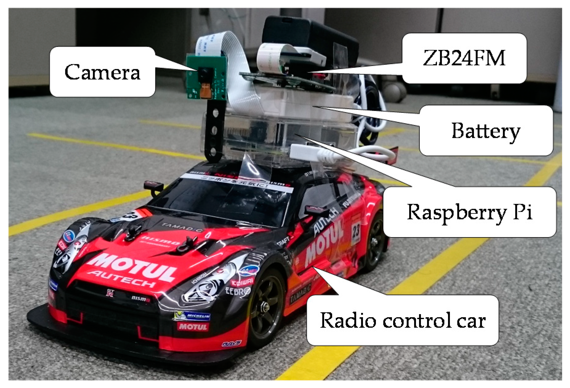
4.1. Experimental System Consisting of Radio Control Cars and Raspberry Pi Computers

A Raspberry Pi 2 model B [12], which is a single-board computer and a Raspberry Pi camera are mounted on each car. Since this camera can take only a video in the front direction, the function of the requesting vehicle identifying the responding vehicle upon receiving a consent message is omitted in the experimental system. Unable to obtain communication modules for inter-vehicle communication, we used, instead, ZB24FM-E2022 [13] (which is based on IEEE 802.15.4) from NEC, which can broadcast messages and does not require authentication before communication. The programs on the experimental system were written in Language C but the program for OpenCV was written in C++. A jumper wire was soldered to the Raspberry Pi’s GPIO pin and to the motor driver of a radio control car [14]. The Raspberry Pi runs the control program on a radio control car. A radio control car autonomously runs in a lane (indicated by vinyl tapes) and stops when it comes to a stop line (also indicated by a vinyl tape) or when it detects a vehicle ahead. Figure 7 shows the experimental system in which a Raspberry Pi computer is attached to each radio control car.

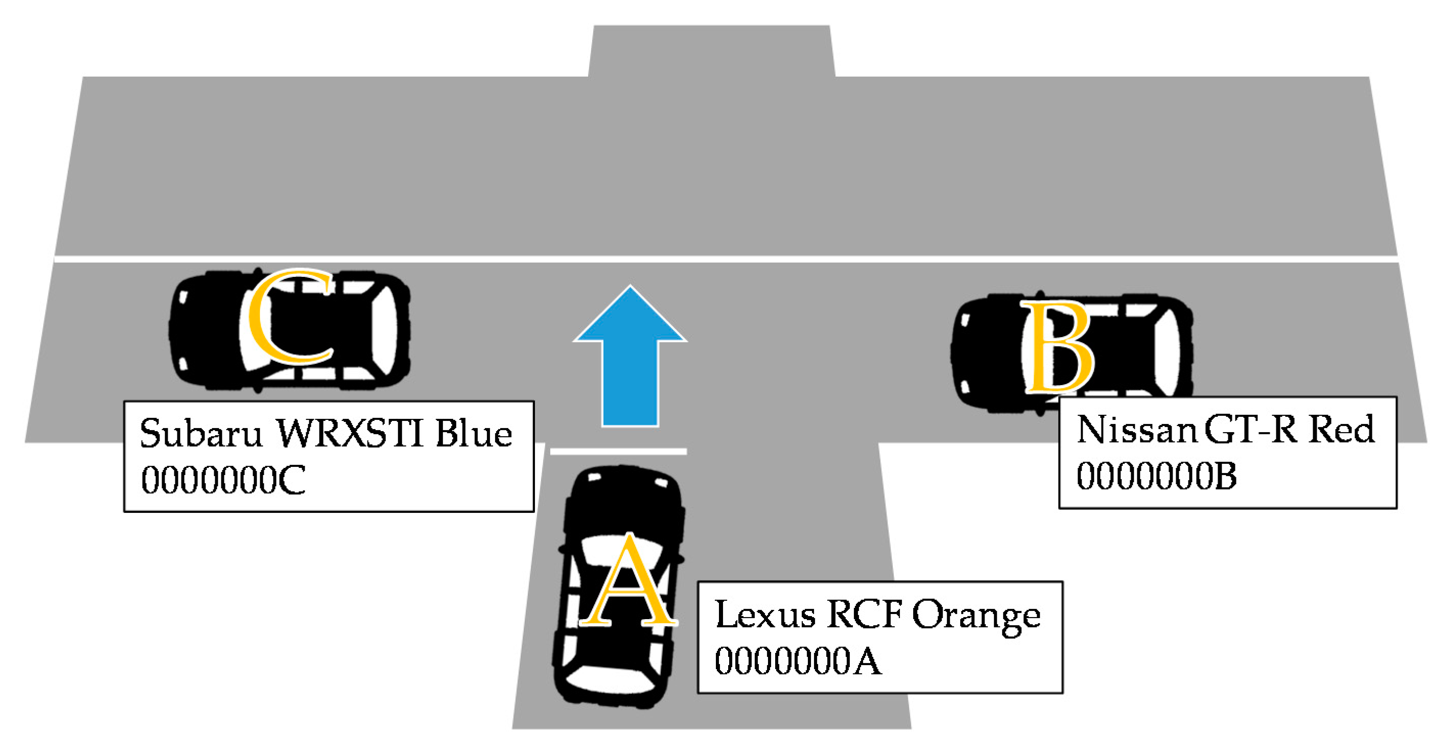
4.2. Recognition of Surrounding Vehicles and the Road Shape at an Intersection

In recent years, methods that use deep learning for recognition of a vehicle model have been proposed [15,16,17]. These methods assume that the system concerned has a powerful computer and incorporates a powerful Graphics Processing Unit (GPU). This paper proposes a yielding protocol, assuming that these are incorporated into ordinary vehicles. The protocol was verified using Raspberry Pi computers, which can be easily implemented in remote control cars. The Raspberry Pi does not have high processing power. The capacity of its hardware, such as GPU, memory and power supply, is also limited. Thus, the Raspberry Pi is not powerful enough for using latest vehicle identification technologies. It would take too long to identify a vehicle, which would make it practically impossible to verify the operation of the proposed protocol. Therefore, we adopted a simplified technology as follow. The proposed system recognizes and identifies surrounding vehicles and also recognizes the road shape to determine which yielding pattern applies by analysing the image of the surroundings captured by the car-mounted camera using OpenCV [18].
For recognition of a vehicle, a cascade classifier that has learned image features is used. When a vehicle receives a message, it identifies the vehicle that has sent the message by selecting an appropriate classifier based on the vehicle information in the message. This means that it is necessary to create a cascade classifier for each model of each vehicle maker. However, since the aim of our experiment was to verify the functionality of the protocol with only three radio control cars, we also made it possible to identify a car by its colour. The RGB values of the average colour of the detected car were compared with the RGB values of the reference colours stored in the system. The reference colour whose RGB values were the least different from those of the detected car was selected. The colour difference in RGB values is calculated using Equation (1).
Color   difference   d = ( r 1 r 2 ) 2 + ( g 1 g 2 ) 2 + ( b 1 b 2 ) 2
(r1, g1, b2): colour of the detected car; (r2, g2, b2): reference colour.
OpenCV’s train cascade was used as a cascade classifier. We developed a classifier that was based on Haar-like features and had learned the features of differences in image contrast. Sample images used for this learning were 150 front view images of vehicles, 150 rear view images and 150 side view images. These were positive images, that is, images that contain vehicle images. We also used 200 randomly selected negative images, that is, images that do not contain vehicle images. If we are to achieve high accuracy in identifying a vehicle, more than 7000 positive sample images and more than 3000 negative sample images would be required. The number of sample images being insufficient, the system might not be able to identify a vehicle with a high level of accuracy. Therefore, a supplementary function of identifying a vehicle by its colour was also provided. The three radio control cars used in the experiment had different colours.
Since the variety of the shapes of the crossroads in the experiments was limited, the road shape was not automatically identified but selected manually.

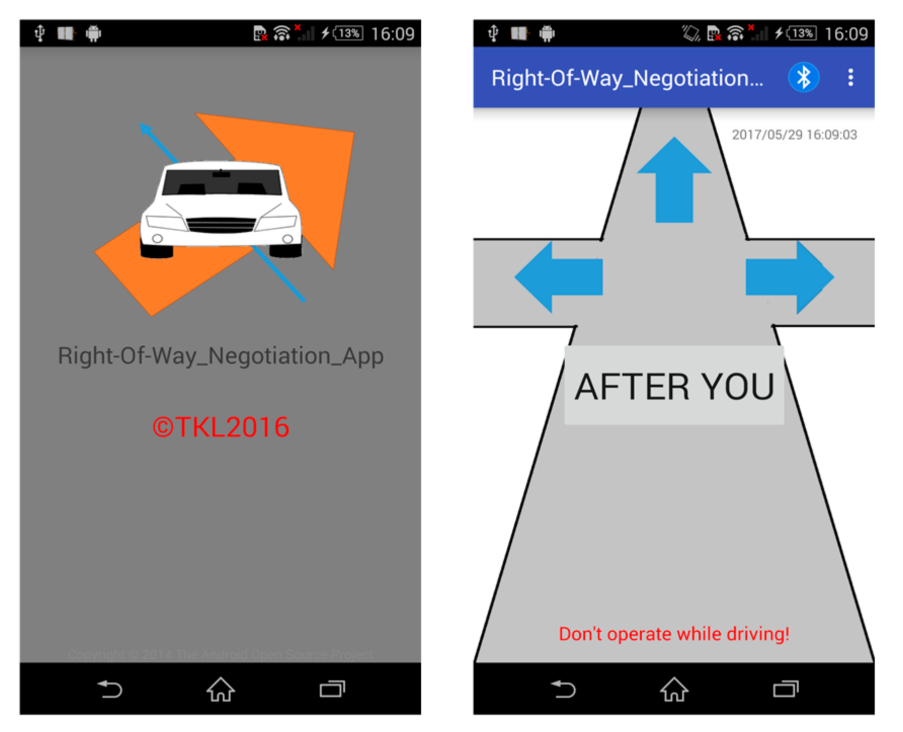
4.3. Human-Machine Interface

The computer of a self-driven vehicle operates the vehicle in accordance with the decision made about yielding. In the case of a human-driven vehicle, the system sends its decision to the driver and the driver makes the final decision and lets the requesting vehicle know the final decision. For this purpose, the system communicates with the driver through a user interface implemented as a smartphone app. The system communicates with the smartphone using Bluetooth, which is a standard and secure means of communication. The operations on the app are so simple that they do not affect driving. The system uses speech to notify the driver of a message that has arrived.
We developed an Android user interface app using Android Studio. It was written in Java. Bluetooth SPP (Serial Port Profile) was used for the app to communicate with Raspberry Pi. In implementing Bluetooth communication, we referred to Bluetooth Chat [19], which is an open source app. The speech messages used by the system for notification were generated using Open JTalk [20]. Operations on the user interface are simple. The driver taps an arrow button to send a request message and a centre button to send a consent message. The buttons are displayed only when operations on these are valid. Figure 8 shows screens of the user interface app.

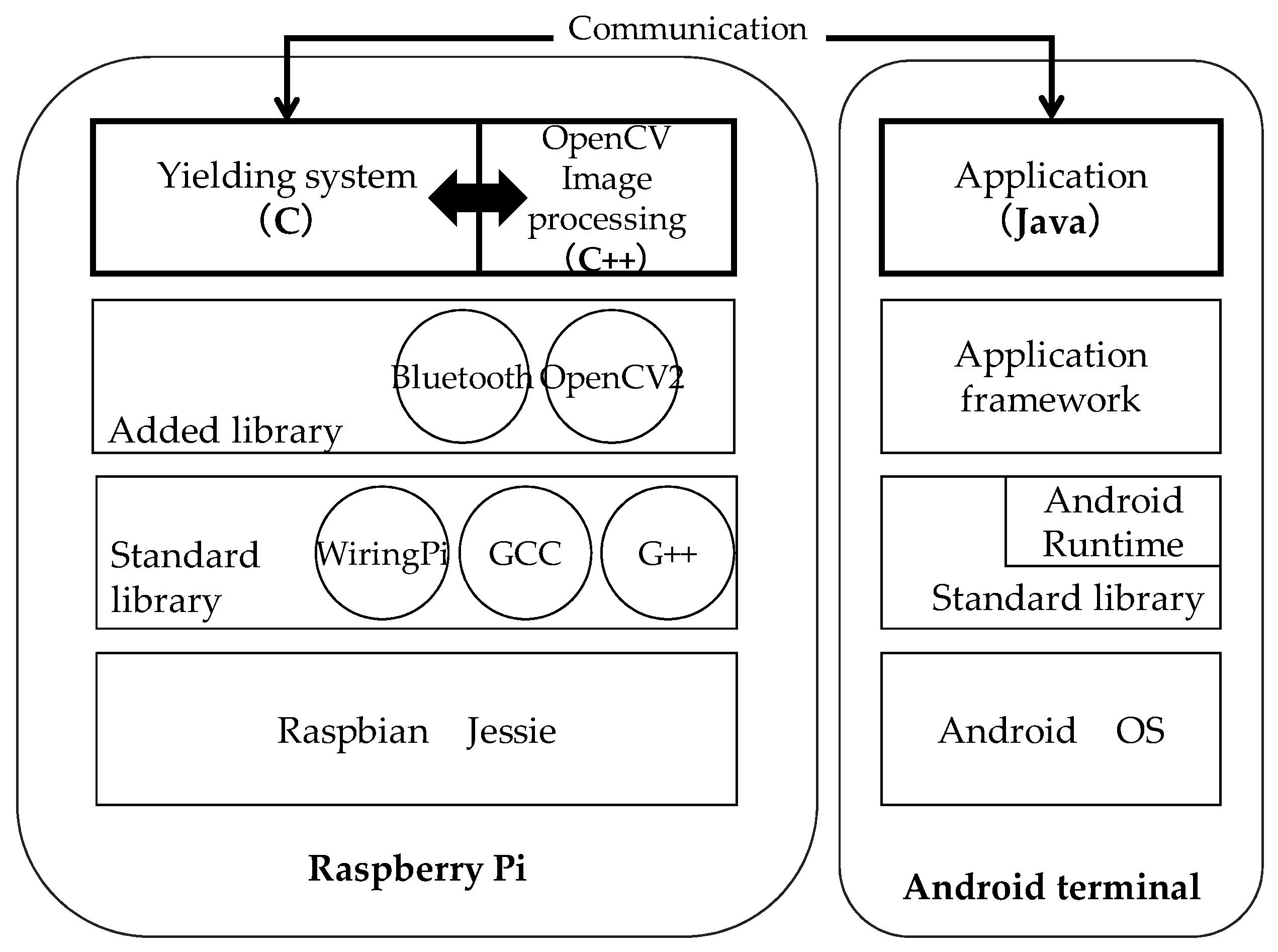
4.4. Software Configuration of the Experimental System

Figure 9 shows the software configuration of the experimental system, including the yielding system and the user interface app for the driver in a human-driven vehicle. The yielding system runs on a Raspberry Pi computer. It calls OpenCV programs to recognize the surroundings. There are three OpenCV programs, one for recognizing a vehicle, one for recognizing the road and one for driving control. Each program is called as necessary. The control of a radio control car is incorporated into the yielding system. Self-driving is achieved by calling the OpenCV program for driving control. In addition to the standard library of Raspberry Pi, Bluetooth, OpenCV2 are added to enable the experimental system to operate.

5. Evaluation

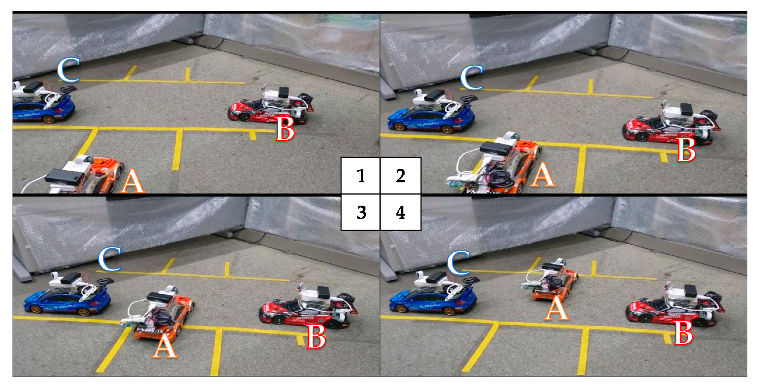
5.1. Evaluation Environment

Figure 10 shows the three radio control cars, their roles and the shapes and priority levels of the roads used in the experiment. Table 5 describes the general experimental conditions. Table 6 shows the experimental conditions of the yielding car in different yielding patterns.
Since this experiment used radio control cars and was conducted within a relatively small room, GPS location information was not used. Yielding request messages from a human-driven vehicle were sent manually using a dedicated application but the driving of a human-driven vehicle was automatically controlled by a program in the experiment for the sake of efficiency. If a radio control car ran fast, the camera on the car swayed so much as to impede image processing. So, radio control cars ran slowly at a speed of 0.3 km/h. Since only a single camera was mounted on a car, it was not possible to check whether there was a car in the back. Thus, this check was omitted. The road width should be automatically identified in a real situation but was manually input in the experiment for the sake of efficiency. A scale of 1/16 was used for the distance and the road width. This scale was derived from the ratio of the size of the radio control car to that of a real car. Since no pedestrians were involved and no cars would disobey system decisions in this experiment, the request message retransmission timer and the thanks message waiting timer would not expire as long as system decisions were correct. Thus, we set the expiration times of these timers to 10 s, which is long enough to prevent the processing of the system from being interrupted due to some processing delay. Since only three cars were running, any decisions that are required only when many cars are running were omitted.

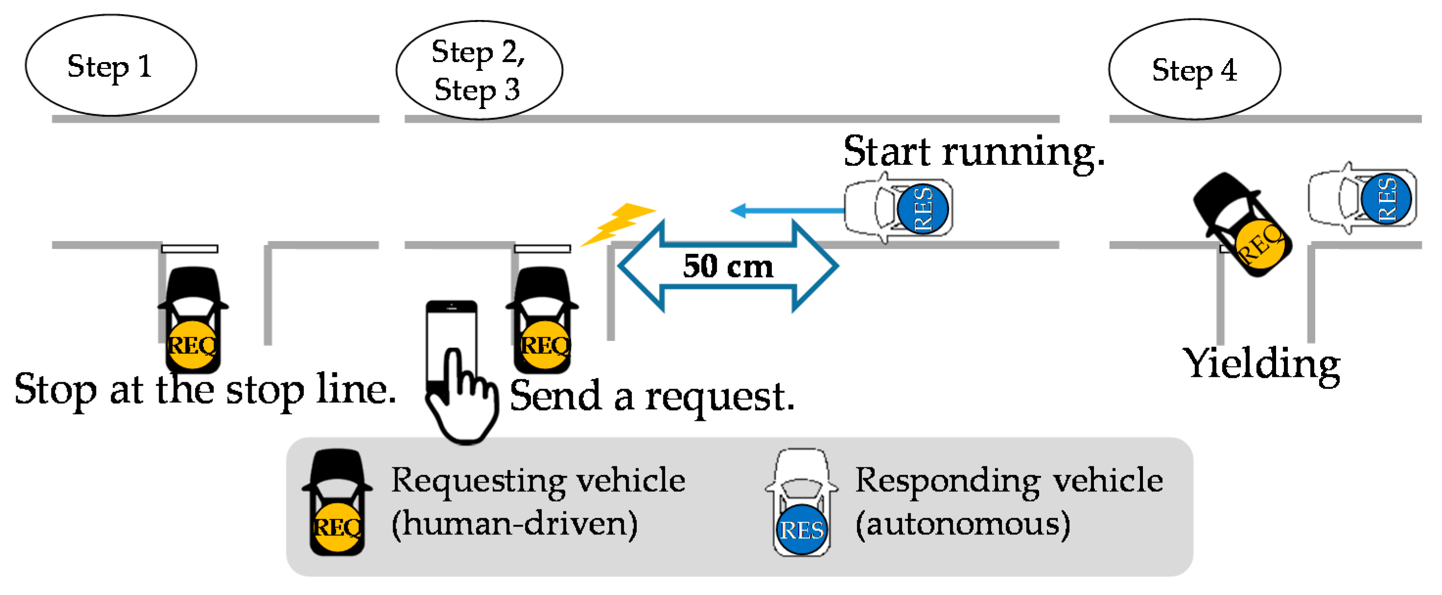
5.2. Evaluation Items and Experiment Methods

We conducted experiments for each yielding pattern in Table 6 and measured the rate of responses to yielding requests (Equation (2)), the average response time (Equation (3)) and the rate of accuracy in yielding decision (Equation (4)).
Response   rate   ( % ) = Number   of   responses   sent   in   reply   to   yielding   requests Number   of   yielding   requests   sent
Average   response   time   ( seconds ) = Total   of   time   lengths   from   yielding   request transmissions   to   response   arrivals   ( seconds ) Number   of   responses   to   yielding   requests
Yielding   accuracy   rate   ( % ) = Number   of   times   when   experiment   results match   assumed   yielding   results Number   of   responses   received   in   reply   to   yielding   requests
The experiment proceeded as shown in Figure 11, in which the vehicles involved ran as follows:
step1.
The requesting vehicle stops at the stop line of the intersection.
step2.
The responding vehicle starts running.
step3.
When the responding vehicle comes to a point about 50 cm from the intersection, it receives a yielding request message on the app.
step4.
The responding vehicle autonomously yields to the requesting vehicle.
Figure 12 shows the case of Pattern 3-a in Table 6, in which yielding occurs successfully. Since there is Vehicle C, which is stopped, ahead of Vehicle B, the latter consents to yield to Vehicle A. Vehicle A moves into the intersection.

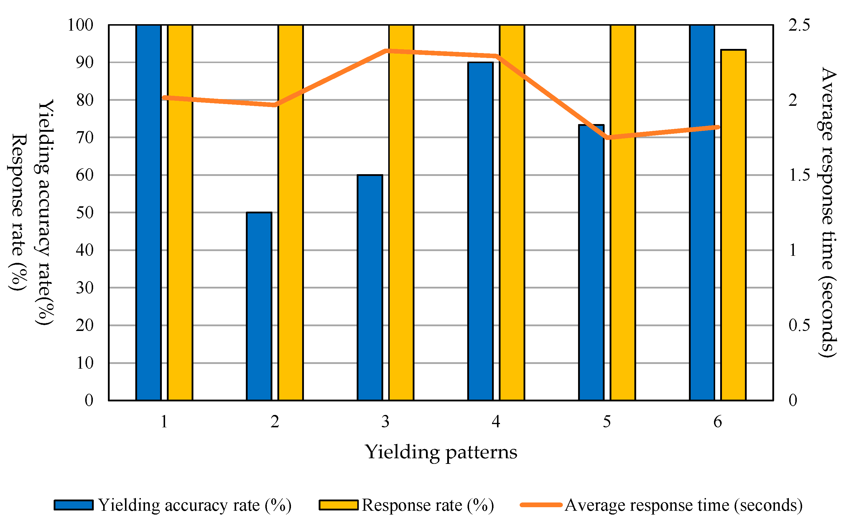
5.3. Experiment Results

It was found that yielding could occur without any problem in all the yielding patterns. Yielding request messages were sent via the dedicated app without any problem.
The average response rate for all patterns was 99%. The average response time was 1.996 s and the yielding accuracy rate was 80%. The results for each yielding pattern are shown in Figure 13. Detailed results are shown in Table 7. The item numbers in Table 7 correspond to the yielding patterns in Table 6.
The yielding accuracy rate was low for Patterns 2, 3 and 5. Most incorrect recognitions in Patterns 2 and 3 occurred in cases where there was a stopped vehicle ahead. This vehicle was incorrectly recognized as an oncoming vehicle. Information about the absence of any oncoming vehicle was not included in the consent message and thus the requesting vehicle was not able to go into the intersection. This was due to low accuracy in detecting vehicles. Since vehicle detection proceeded from checking a stopped vehicle ahead to checking an oncoming vehicle, the vehicle detected as a stopped vehicle ahead was also detected as an oncoming vehicle. It is necessary to change this vehicle detection mechanism to one by which the two types of vehicle can be detected simultaneously. In Pattern 5, wrong decisions occurred in cases where the responding vehicle was in the opposite lane. These happened because the requesting vehicle incorrectly recognized the responding vehicle as being on its right side. The requesting vehicle detected the location of the responding vehicle using an image captured by its camera. It is necessary to improve vehicle detection accuracy and introduce a mechanism by which the vehicle direction can also be identified.
The response time ranged from 1.4 to 3 s. The average was about 2 s. These values are acceptable considering the specifications of the Raspberry Pi computer used in the experimental system. If humans were involved, the time they spend to check the surroundings might range more widely. The fact that the response time was within 3 s without wide deviation, which can occur if humans were involved, suggests that the proposed system is useful. The response time can be reduced by improving the performance of the devices used in the experimental system.

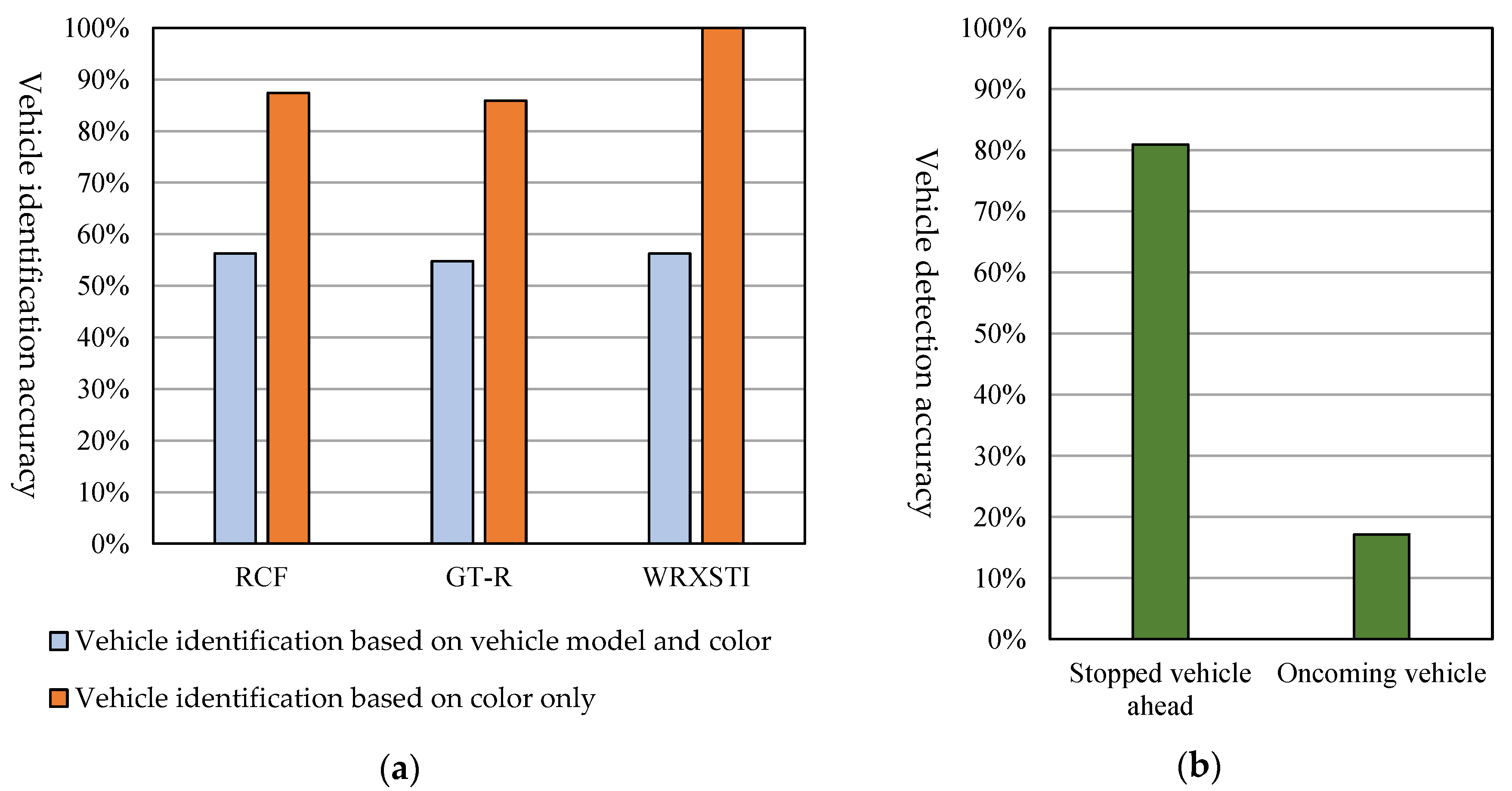
5.4. Vehicle Identification Accuracy and Vehicle Detection Accuracy

High vehicle detection accuracy is critical to accurate decision-making in the proposed system. Since there were incorrect recognitions and detections in the above operating experiment, we conducted an additional experiment to measure vehicle identification accuracy and vehicle detection accuracy.
The experimental conditions of this experiment were the same as those used in the above experiment. Experiments were conducted for situations in Patterns 1 to 3, situations in Pattern 4 and situations in Patterns 5 and 6. The results of the requesting vehicle identifying the responding vehicle (for each vehicle model) and detecting a stopped vehicle ahead and an oncoming vehicle were recorded. The vehicle identification and vehicle detection accuracy were calculated from these. The calculated vehicle identification and detection accuracies are shown in Figure 14. RCF, GT-R and WRXSTI represent vehicle models and correspond to Vehicles A, B and C in Figure 12.
The average accuracy for identifying the vehicle model was as low as 55%. This reflected the fact that the detector had not learned sufficiently, as was mentioned in Section 4.2. In the experimental system, if a vehicle failed to identify a vehicle by its vehicle model and colour, it relied on the colour only. This was why the system operated without a problem in the above operational experiment. However, it is clear that an important future study issue is to enhance vehicle identification accuracy. While a stopped vehicle ahead was detected more or less accurately, an oncoming vehicle was seldom detected.
These results suggest that the low detection accuracy is due to the low accuracy of the detector and to the dependence on the vehicle location. Since the cameras used in the experimental system have a narrow angular field, they cannot capture the entire parts of vehicles that exist on the right and left. This may explain why the detector failed to find vehicles. An oncoming vehicle was detected if it was near the requesting vehicle but was seldom detected if it was far. Considering that detection failure can also occur if there are obstacles, it is necessary for the detector to learn cases where a vehicle is only partially visible or where a vehicle is far away.
There are some alternative methods that use deep learning to identify a vehicle model with a high level of accuracy [15,16,17]. The method in Reference [15] can identify a vehicle only from its front image but can identify a vehicle within about one second using only a CPU and records a vehicle identification accuracy of 98.5%. The method in Reference [16] identifies a vehicle from any direction within about 0.3 s using a GPU and achieves an identification accuracy of 94.7%. It makes its detector learn using VGG16Net [16]. The method in Reference [17] also identifies a vehicle from any direction and achieves an identification accuracy of 93.6% to 95.9% using the vehicle identification system of Sighthound [17]. In this way, research on vehicle identification is advancing with an aim of application to commercial services and is expected to further raise the identification accuracy. With the advances in hardware technology and emergence of the Tensor Processing Unit (TPU) [21], which is specialized to machine learning using GPU, instantaneous vehicle identification will become possible.

6. Conclusions

This paper has proposed a yielding system that enables vehicles to decide to yield the right of way depending on the traffic on the road without using a roadside unit. With this system, a vehicle at an unsignalized intersection makes a yielding-related decision by recognizing surrounding vehicles and the road shapes using a vehicle-mounted camera and conveys its decision to other vehicles using peer-to-peer (P2P) communication. To verify the effectiveness of the proposed yielding system, we implemented the yielding system in an experimental system, which consisted of Raspberry Pi computers, which were mounted on radio control cars. The computers had the yielding function and a function to recognize a vehicle from an image captured by a camera mounted on a radio control car. Using this experimental system, we conducted operating experiments and confirmed that the proposed system enables vehicles at an unsignalized intersection to decide to yield the right of way by making inter-vehicle communication. It was found that it is necessary to improve vehicle detection accuracy and enhance the performance of devices used.
However, vehicles sometimes made incorrect yielding decisions in the experiment. Since, in making a yielding decision, the system checks whether the vehicle involved is slow enough to allow safe yielding before it checks the surrounding conditions, incorrect decisions due to erroneous vehicle detections would reduce traffic efficiency. In addition, when vehicles cannot identify other vehicles, no yielding decision is made to ensure safety. However, if yielding occurs only infrequently, the yielding system is meaningless. Therefore, a major issue is to raise the vehicle identification rate by recognizing a vehicle based on its vehicle model. Other future issues include verification of the yielding system when it is combined with GPS, which was not used in the experiments and implementation of motion tracking. In addition, since we conducted the operating experiment using radio control cars, we were not able to verify system operations at normal vehicle speed using communication that covers a wide area and to use a standard communication system for inter-vehicle communication. Experiments under these conditions are essential if we are to introduce the proposed system on real roads. We assumed that vehicle running information can be obtained by connecting vehicles to a CAN. However, this connection establishes a route for accessing the Engine Control Unit (ECU) from outside. Therefore, it is necessary to study security issues.
Looking forward, we will conduct simulation with the number of vehicles comparable to that in real situations in order to evaluate how much the proposed yielding system improves traffic flow. We have not yet specified details about yielding decision criteria, such as the timeout length, the number of queuing vehicles and presence of a vehicle in the back. Through simulation, we will derive criteria that will lead to the most efficient traffic flow. Since the currently identified yielding patterns do not cover all the possible situations, we will study how to adapt the system for new patterns for situations not yet considered and also study the use of deep learning to enhance vehicle detection accuracy. The clarity of images captured by a camera is affected by the weather and brightness. It is necessary to address this problem before self-driven vehicles become widely used because it is necessary to detect buildings and humans even though they do not communicate with vehicles.

Author Contributions

H.Y. designed the proposed method, developed the software prototype of the evaluation system, collected the evaluation data and wrote the initial draft of the paper. K.T. provided the direction for his research activities and refined the proposed method, the analysis of the evaluation results and the writing of the paper.

Funding

This research received no external funding.

Conflicts of Interest

The authors declare no conflict of interest.

References

  1. Cross-Ministerial Strategic Innovation Promotion Program (SIP)—Innovation of Automated Driving for Universal Services, Research & Development Plan, Cabinet Office, Government of Japan (Online). Available online: http://www8.cao.go.jp/cstp/gaiyo/sip/keikaku/6_jidousoukou.pdf (accessed on 5 September 2017).
  2. Xu, B.; Ban, X.; Bian, Y.; Wang, J.; Li, K. V2I based cooperation between traffic signal and approaching automated vehicles. In Proceedings of the Intelligent Vehicles Symposium, Los Angeles, CA, USA, 11–14 June 2017; pp. 1658–1664. [Google Scholar] [CrossRef]
  3. Tran, H.K.; Ideguchi, T.; Okuda, T.; Xuejun, T. A consideration for consensus formation on t-crossing utilizing inter-vehicle communication. In Proceedings of the Multimedia, Distributed, Corporative, and Mobile Symposium (DICOMO), Beppu-shi, Japan, 8–10 July 2009; pp. 252–257. [Google Scholar]
  4. Ozaki, H.; Nagao, K. A Traffic accident prevention system using autonomous driving control at intersection area. In Proceedings of the 70th National Convention of IPSJ, Tukuba-shi, Japan, 13–15 March 2008; pp. 311–312. [Google Scholar]
  5. Hausknecht, M.; Au, T.; Stone, P. Autonomous intersection management: multi-intersection optimization. In Proceedings of the International Conference on Intelligent Robots and Systems Conference, San Francisco, CA, USA, 25–30 September 2011; pp. 4581–4586. [Google Scholar]
  6. Yang, B.; Zheng, R.; Shimono, K.; Kaizuka, T.; Nakano, K. Evaluation of the effects of in-vehicle traffic lights on driving performances for unsignalized intersections. IET Intell. Transp. Syst. 2017, 11, 76–83. [Google Scholar] [CrossRef]
  7. Yang, B.; Zheng, R.; Kaizuka, T.; Nakano, K. Influences of waiting time on driver behaviors while implementing in-vehicle traffic light for priority-controlled unsignalized intersections. J. Adv. Transport. 2017, 7871561. [Google Scholar] [CrossRef]
  8. IEEE 802.11p-2010. Available online: https://standards.ieee.org/standard/802_11p-2010.html (accessed on 11 April 2017).
  9. Dedicated Short-Range Communication System (ARIB). Available online: http://www.arib.or.jp/english/html/overview/doc/5-STD-T75v1_0-E2.pdf (accessed on 11 April 2017).
  10. 700 MHz Band Intelligent Transport System (ARIB). Available online: http://www.arib.or.jp/english/html/overview/doc/5-STD-T109v1_2-E1.pdf (accessed on 11 April 2017).
  11. 700 MHz Band Intelligent Transport SYSTEMS—Experimental Guideline for Inter-Vehicle Communication Messages (ITS Info-Communications Forum). Available online: http://www.itsforum.gr.jp/Public/J7Database/p48/ITS_FORUM_RC-013_v10.pdf (accessed on 6 December 2016).
  12. Raspberry Pi 2 Model B (The Raspberry Pi Foundation). Available online: https://www.raspberrypi.org/products/raspberry-pi-2-model-b (accessed on 18 January 2016).
  13. Proprietary Protocol—Serial Communication Module (ZB24FM-E2022-01) (NEC Corporation). Available online: http://jpn.nec.com/engsl/pro/wireless/serial_module.html (accessed on 13 April 2016).
  14. Self Driving RC Car. Available online: https://zhengludwig.wordpress.com/projects/self-driving-rc-car/ (accessed on 25 May 2016).
  15. Gao, Y.; Lee, H.J. Local tiled deep networks for recognition of vehicle make and model. Sensors 2016, 16, 226. [Google Scholar] [CrossRef] [PubMed]
  16. Zhao, S.; Zhu, X.L.; Li, Y.B.; Zhang, L. Research on the recognition of car models based on deep-learning networks. In Proceedings of the 2017 Asia-Pacific Engineering and Technology Conference, Lancaster, PA, USA, 25–26 May 2017; pp. 1770–1775. [Google Scholar]
  17. Dehghan, A.; Masood, S.Z.; Shu, G.; Ortiz, E.G. View independent vehicle make, model and color recognition using convolutional neural network. arXiv, 2017; arXiv:1702.01721. [Google Scholar]
  18. OpenCV. Available online: http://opencv.org/about.html (accessed on 2 November 2016).
  19. Android BluetoothChat Sample (Google, GitHub). Available online: https://github.com/googlesamples/android-BluetoothChat (accessed on 30 August 2016).
  20. Open JTalk. Available online: http://open-jtalk.sourceforge.net/ (accessed on 7 October 2016).
  21. Jouppi, N.P.; Young, C.; Patil, N.; Patterson, D.; Agrawal, G.; Bajwa, R.; Bates, S.; Bhatia, S.; Boden, N.; Borchers, A.; et al. In-datacenter performance analysis of a tensor processing unit. In Proceedings of the 2017 ACM/IEEE 44th Annual International Symposium on Computer Architecture (ISCA), Toronto, ON, Canada, 24–28 June 2017; pp. 1–12. [Google Scholar] [CrossRef]
Figure 1. Yielding procedure example at an unsignalized intersection on a crossroads of a priority road and a low-priority road. (a) Situation at an unsignalized intersection: Vehicle A wants to go straight ahead. It stops at the stop line at the intersection and negotiates with Vehicle B; (b) Inter-vehicle communication sequence example in which Vehicle A makes a request and Vehicle B consents and yields.
Computers 08 00016 g001
Figure 2. State transition diagram for yielding decision.
Computers 08 00016 g002
Figure 3. Yielding decision flowcharts. (a) Pattern 1 (turn left from a low-priority road to a priority road) and Pattern 4 (turn right from a priority road to a low-priority road); (b) Pattern 2 (turn right from a low-priority road to a priority road) and Pattern 3 (cross a priority road from a low-priority road); (c) Pattern 5 (go straight at an intersection of two roads of the same width); (d) Pattern 6 (turn right at an intersection of two roads of the same width).
Computers 08 00016 g003aComputers 08 00016 g003b
Figure 4. Example of an assumed inter-vehicle communication protocol stack for implementing the yielding function (Vehicle B can be a self-driven vehicle).
Computers 08 00016 g004
Figure 5. Road condition.
Computers 08 00016 g005
Figure 6. Message sequence examples. (a) Vehicle A receives consent and yielding occurs without a problem; (b) Although Vehicle A has received consent, yielding is cancelled due to overtime.
Computers 08 00016 g006
Figure 7. Experimental system in which a Raspberry Pi computer is attached to each radio control car.
Computers 08 00016 g007
Figure 8. Screens of the user interface app for the driver in a human-driven vehicle.
Computers 08 00016 g008
Figure 9. Software configuration of the experimental system.
Computers 08 00016 g009
Figure 10. Experimental system on a crossroads of a priority road and a low-priority road.
Computers 08 00016 g010
Figure 11. Experiment sequence.
Computers 08 00016 g011
Figure 12. Scenes of Pattern 3-a in Table 6 (Vehicle B on the priority road yields to Vehicle A on the low-priority road and Vehicle A crosses the priority road).
Computers 08 00016 g012
Figure 13. Average measurements for each yielding pattern.
Computers 08 00016 g013
Figure 14. Results of the vehicle identification and detection accuracy experiment. (a) Rate of correctly identifying the communicating vehicle (identification based on vehicle model and colour and identification based on colour only); (b) Rate of correctly detecting surrounding vehicles (stopped vehicle ahead and oncoming vehicle) at the time of yielding decision.
Computers 08 00016 g014
Table 1. Comparison of the various traffic control methods at an intersection and the proposed method.
Comparison Item MethodTraffic LightRoadside UnitIntersection ShapeA Mix of Self-Driven and Human-Driven Vehicles
Optimization of signal change timing [2]PresentPresentCrossroads with no priority given to any roads and with separate lanes for different directionsSelf-driven vehicles only
Yielding control based on request and consent [3]Not presentNot presentT-shaped intersection where a priority road and a low-priority road meetHuman-driven vehicles only
Adjustment of vehicle speeds [4]PresentCrossroads with no priority given to any roadsSelf-driven vehicles only
Intersection passing order control [5]
Display of virtual traffic lights based on distances between vehicles [6,7]Not presentCrossroads of a priority road and a low-priority roadHuman-driven vehicles only
Proposed methodCrossroads of a priority road and a low-priority road and crossroads with no priority given to any roadsMixed
Table 2. Yielding patterns.
Pattern NumberDescriptionSchematic View (The Lanes Are Drawn in Accordance with the Japanese Traffic Rules)
1A vehicle wants to turn left from a low-priority road to a priority roadComputers 08 00016 i001
2A vehicle wants to turn right from a low-priority road to a priority road
3A vehicle wants to cross a priority road from a low-priority road
4A vehicle wants to turn right from a priority road to a low-priority roadComputers 08 00016 i002
5A vehicle wants to go straight at an intersection of two roads of the same width (no priority assigned)
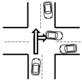
Computers 08 00016 i003
6A vehicle wants to turn right at an intersection of two roads of the same width (no priority assigned)
Table 3. Message elements and format.
Header/BodyElementSymbolData Example
Message headerSystem ID (4 bytes)h10x01595257
Message length (1 byte)h20x11
DestinationID (4 bytes)h30x01234567
SenderID (4 bytes)h40x89ABCDEF
Vehicle informationMaker (1 byte)h50x01
Vehicle model (1 byte)h60x03
Colour (1byte)h70x0b
Location information (GPS)Latitude (4 bytes)h80x420EC0B8
Longitude (4 bytes)h90x430B545E
Message bodyYielding pattern number (4 bits)b10001
Requester confirmation bit (1 bit)b21
Message type (3 bits)b3000
Spare (0 to 7 bytes)b4
Table 4. Some of the specific message elements used in the message sequences (a) and (b) in Figure 6.
No.Message DirectionMessage ElementDataMeaning
m1 A-> All vehicles
Request for going straight ahead
h3 0xffffffff Broadcast
h4 0x0000000a 0000000A
h5,6,7 0x08,08,03 Lexus RCF Orange
b1 0011 Pattern 3
b2 1 Yielded-to side
b3 010 Request for going straight ahead
m2 C -> A
Refusal
h3 0x0000000a 0000000A
h4 0x0000000c 0000000C
h5,6,7 0x04,03,08 Subaru WRXSTI Blue
b1 0011 Pattern 3
b2 0 Yielding side
b3 100 Refusal
m3 B -> A
Consent
h3 0x0000000a 0000000A
h4 0x0000000b 0000000B
h5,6,7 0x01,06,01 Nissan GT-R Red
b1 0011 Pattern 3
b2 0 Yielding side
b3 011 Consent
b4 0x01 No oncoming vehicle
m4 A -> B
Thanks
h3 0x0000000b 0000000B
h4 0x0000000a 0000000A
h5,6,7 0x08,08,03 Lexus RCF Orange
b1 0011 Pattern 3
b2 1 Yielded-to side
b3 101 Thanks
m5 B -> A
Timeout
h3 0x0000000a 0000000A
h4 0x0000000b 0000000B
h5,6,7 0x01,06,01 Nissan GT-R Red
b1 0011 Pattern 3
b2 0 Yielding side
b3 110 Timeout
m6A -> B
Timeout
h3 0x0000000b 0000000B
h4 0x0000000a 0000000A
h5,6,7 0x08,08,03 Lexus RCF Orange
b1 0011 Pattern 3
b2 1 Yielded-to side
b3 110 Timeout
Table 5. Experimental conditions (common to all yielding patterns).
ItemConditions
PlaceIndoor
Number of vehicles3
Vehicle typeSelf-driven vehicle (yielding side)
Human-driven vehicle (yielded-to side)
Moving direction (yielding side)Always moving straight ahead
Running speedSpeed at which it is easy to stop
Congestion in the opposite laneNone
Checking of the following vehicleNone
ObstaclesNone
Identification of the road shapeManual input
Distance scale1/16
Yielding patterns used1 to 6
Value for the request message retransmission timer10 s
Value for the thanks message waiting timer10 s
Number of experiments5 (for each condition in Table 6)
Table 6. Experimental conditions of the yielding vehicle in different yielding patterns.
Yielding Pattern NumberConditions (Identification Symbol, Description)Result Assumed by the Proposed System
1aThere is a stopped vehicle ahead.Yield
bThere is no stopped vehicle ahead.Not yield
2aThere is a stopped vehicle ahead.Yield
bThere is no stopped vehicle ahead.Not yield
3aThere is a stopped vehicle ahead.Yield
bThere is no stopped vehicle ahead.Not yield
4aThere is a stopped vehicle ahead.Yield
bThere is no stopped vehicle ahead.Not yield
5aThe requesting vehicle is on the left.Yield
bThe requesting vehicle is on the right.Not yield
cThe requesting vehicle is in the opposite lane.Consent (move on)
6aThe requesting vehicle is on the left.Yield
bThe requesting vehicle is on the right.Not yield
cThe requesting vehicle is in the opposite lane.Not yield
Table 7. Detailed experiment results. Item numbers correspond to the yielding patterns in Table 6; R: Response; A: Accuracy; RT: Response Time (seconds); G: Good; B: Bad; MF: Measurement failure.
Item No.Experiment ResultsCauseItem No.Experiment ResultsCause
RARTRART
1-aGG2.202 4-bGG2.311
GG2.220 GG1.831
GG2.099 GG1.876
GG2.322 GG2.426
GG2.045 GB2.435The vehicle ahead incorrectly detected.
1-bGG1.631 5-aGG2.014
GG1.726 GG1.416
GGMF GG1.934
GG1.944 GG1.467
GG1.958 GG1.995
2-aGB2.004The vehicle ahead incorrectly recognized as an oncoming vehicle.5-bGG1.767
GB2.127GG1.402
GB1.807GG2.046
GB1.931GG1.678
GBMFVehicles cannot be identified.GG1.827
2-bGGMF 5-cGG1.977
GG1.611 GB1.383The responding vehicle incorrectly recognized as being on the right side.
GG2.636 GB1.997
GG1.645 GB1.615
GGMF GB1.726
3-aGG2.530 6-aGGMF
GB2.293The vehicle ahead incorrectly recognized as an oncoming vehicle.GG1.525
GB2.380GG1.927
GB2.405GG1.697
GB2.438GG1.902
3-bGG2.991 6-bGG2.149
GG2.009 GG1.801
GG2.048 GG1.428
GG2.083 B Unknown (possibly failure in synchronization with the communication module?)
GG2.099 GG2.065
4-aGGMF 6-cGG1.987
GG2.098 GG2.117
GG2.971 GG1.735
GG2.025 GG1.851
GG2.662 GG1.474

