Article

High Dynamic Range Image Deghosting Using Spectral Angle Mapper

by
Muhammad Murtaza Khan
College of Computer Science and Engineering, University of Jeddah, 21959 Jeddah, Saudi Arabia
Computers 2019, 8(1), 15; https://doi.org/10.3390/computers8010015
Submission received: 31 December 2018 / Revised: 5 February 2019 / Accepted: 6 February 2019 / Published: 9 February 2019

Abstract

:
The generation of high dynamic range (HDR) images in the presence of moving objects results in the appearance of blurred objects. These blurred objects are called ghosts. Over the past decade, numerous deghosting techniques have been proposed for removing blurred objects from HDR images. These methods may try to identify moving objects and maximize dynamic range locally or may focus on removing moving objects and displaying static objects while enhancing the dynamic range. The resultant image may suffer from broken/incomplete objects or noise, depending upon the type of methodology selected. Generally, deghosting methods are computationally intensive; however, a simple deghosting method may provide sufficiently acceptable results while being computationally inexpensive. Inspired by this idea, a simple deghosting method based on the spectral angle mapper (SAM) measure is proposed. The advantage of using SAM is that it is intensity independent and focuses only on identifying the spectral—i.e., color—similarity between two images. The proposed method focuses on removing moving objects while enhancing the dynamic range of static objects. The subjective and objective results demonstrate the effectiveness of the proposed method.

1. Introduction

Conventional sensors are unable to match the range of luminance that is captured by the human eye. Hence, the images obtained by conventional capturing devices suffer from a lower dynamic range compared to what is perceived by the human visual system. A natural scene may comprise of both bright and dark regions. The light captured by the sensor will depend on the exposure time and shall result in the capture of bright, dark or medium range features. If the exposure time is small, then only bright objects will be clearly visible in the captured image, while darker objects will appear black. If the exposure time is increased, dark objects start becoming visible; however, bright objects will become over-exposed or washed out in the image. This means that if you take a photograph standing in a room with the intention of capturing both the objects inside the room and outside the window, the camera will only be able to capture either what is inside the room or what is outside the window. Mimicking the human visual system, which is capable of seeing both inside the room and outside at the same time, researchers have proposed the generation of high dynamic range (HDR) images using multiple low dynamic range (LDR) images. The LDR images are captured at different exposure settings and therefore are capable of capturing objects with different intensity. Fusing them together results in an image with visible bright and dark objects.
Generally, a sequence of successive LDR images is captured—i.e., captured sequentially in time and with varying exposure—to generate an HDR image. The slight delay in changing the exposure setting and capturing the images may result in movement of objects in the scene. This movement of objects results in the issue of ghosting in generated HDR images. Ghosting may also be caused because of camera movement. However, in the course of this work, we shall not consider the case of camera movement and assume that ghosting has been caused because of the movement of objects. Numerous deghosting methods have been proposed over the past decade and will be discussed in detail in the next section. One of the most popular among them is based on identifying ghost pixels—i.e., pixels which have moved between images—and excluding them from the process of HDR image generation. If these pixels are not replaced appropriately, their absence would result in a hole in the generated HDR image. One solution is to replace these pixels by corresponding pixels from a reference image. This paper proposes the use of a spectral angle mapper (SAM) to identify ghost pixels and replace these pixels using a reference image with average exposure settings. The advantage of SAM is that it is illumination invariant and, hence, can be used to match the spectral signature of two pixels across images with varying exposures. This property makes SAM an ideal candidate for deghosting, even in the absence of image exposure values.
The rest of the paper is organized as follows. Section 2 presents a brief overview of the state-of-the-art in the area of deghosting for the generation of HDR images. Section 3 presents the proposed methodology. Section 4 introduces the dataset used and a comparison with existing HDR deghosting methods. Conclusions are presented in Section 5.

2. Literature Review

Deghosting is a topic that has been researched extensively over the past decade. In a recent survey, Tursun et al. classified HDR image deghosting methods into global exposure registration, moving object removal, moving object selection and moving object registration [1]. Following the global exposure registration approach, Ward proposed a multi-resolution analysis method for removing the translational mis-alignment between captured images using pixel median values [2]. Cerman et al. [3] proposed to remove both translation and rotation-based mis-alignment using correlation in the frequency domain. Gevrekci et al. proposed using the contrast invariant feature transform (CIFT) for geometric registration of multi-exposure images, as CIFT does not require photometric registration as a pre-requisite for geometric registration [4]. Tomaszewska et al. [5] proposed extraction of spatial features using the scale invariant feature transform (SIFT) and the estimation of a planar homography between two multi-exposure images using random sample consensus (RANSAC). In [6], Im et al. proposed the estimation of affine transformation between multi-exposure images by minimizing the sum of square errors. In 2011, Akyuz et al. [7] proposed a method inspired by Ward’s method of testing pixel order relations. They identified that pixels having smaller intensity as compared to their bottom neighbor and higher intensity as compared to their right neighbor should have the same relation across exposures. They observed a correlation between such relations and minimized hamming distance between correlation maps for alignment.
To address the issue of object movement, researchers have focused on identifying and removing moving objects from multiple exposures. In this regard, Khan et al. [8] proposed the removal of moving objects from HDR images iteratively. This was done by estimating the probability that each pixel is a background pixel—i.e., a static region—and separating it from non-static pixels. Granados et al. [9] proposed the minimization of an energy function comprising data, smoothness and hard constraint terms using graph cuts. Silk et al. [10] proposed the estimation of an initial motion mask using the absolute difference between two exposures. The motion mask was further refined by over-segmenting the super-pixels and then categorizing them into static or moving regions and assigning them less or more weight during HDR generation, respectively. Zhang et al. proposed an HDR generation method utilizing gradient domain-based quality measures [11]. They proposed using visibility and consistency scores by assigning higher visibility score to pixels with larger gradient magnitudes and a higher consistency score if corresponding pixels had the same gradient direction.
Kao et al. [12] estimated moving pixels using block-based matching between two exposures with ±2 EV difference. This meant that the intensities in the image with longer exposure should be scaled by a factor of 4; i.e., L2 = 4 L1. If this was not true, this would be an indication of potential movement, and the pixel would be replaced by a scaled version of the pixel from a shorter-exposure image. In [13], Jacobs et al. proposed using uncertainty images, which are generated by calculating a variance map and entropy around object edges and checking if entropy changes for moving objects. The motion regions were replaced by a corresponding region of input exposure with the least amount of saturation and longest exposure time. In [14], Pece and Kautz proposed motion-region detection using bitmap movement detection (BMD) based on median thresholding followed by refinement of the motion map using morphological operators. In [15], Lee et al. proposed using the histogram of pixel intensities to detect ghost regions. They identified large differences in the rank of pixels as a ghost region. In [10], Silk et al. proposed focusing on addressing movement due to fluttering or fluid motion by maximizing the sum of pixel weights in the region affected by motion. In [16], Khan et al. proposed a simple deghosting method which assumed that a group of N pixels with intensity I1 should have intensity I2 in a second exposure. I2 is sampled as the median value for the same group of N pixels in the second exposure. Assuming that M pixels in the second exposure differ from I2 by a threshold, they are assigned the value I2 to remove motion. Shim et al. addressed the issue of avoiding saturated pixels while generating an HDR image [17]. They proposed a scaling function to estimate the scaling of static unsaturated pixels between each input image and a reference exposure. In [18], Liu et al. proposed the use of dense scale invariant feature transform (DSIFT) for motion detection. Unlike SIFT, DSIFT is neither scale nor rotation invariant; however, it provides a per pixel feature vector and, hence, each pixel among two images can be checked for similarity. In a patch-based approach [19], Zhang et al. proposed the calculation of correlation between local patches of reference and input images. The authors referred to the motion-free images as latent images. They further proposed the preservation of details by optimizing a contrast-based cost function. Chang et al. proposed the identification of areas with motion by calculating motion weights using a bidirectional intensity map and generated latent images using weight optimization in the gradient domain [20]. In [21], Zhang et al. proposed the estimation of inter-exposure consistency using histogram matching. To further restrain the outliers from contributing to the generation of HDR, they proposed using intra-consistency, which is motion detection at the super-pixel level. This helped assign similar weights to structures with similar intensities and structures.
Raman et al. proposed using the first few horizontal lines along the image border to identify the intensity map function (IMF) [22]. Next, different rectangular patches were compared between the input and reference image. If the patches did not adhere to the intensity map function, it was assumed to have motion. Sen et al. [23], proposed the use of a patch-based minimization of energy function, comprising a bidirectional similarity measure. Li et al. proposed a simple approach based on a bidirectional pixel similarity measure in [24]. In [25], Srikantha et al. assumed that input images have a linear camera response function (CRF). Only non-static pixels will not adhere to the linear CRF and, hence, will have smaller values when singular value decomposition (SVD) is applied to them. Sung et al. proposed an approach based on zero-mean normalized cross-correlation to estimate motion regions [26]. Wang et al. proposed the normalization of each input image with a reference image (exposure) in Lab color space [27]. The ghost mask was obtained using a threshold on the absolute difference map between reference and normalized input images in the Lab color space. As ghost masks contained holes, they proposed the use of morphological operations for refining the masks.
In [28], Hossain et al. proposed the estimation of dense motion fields using optical flow to minimize forward and backward residuals. They believed that an effective intensity mapping function could be estimated if each pixel in each exposure was assigned occlusion weights using histograms. This method falls in the category of methods focusing on moving object registration. Jinno et al. proposed modelling displacement, occlusion and saturation regions using Markov random fields and minimized an energy function comprising the three defined terms [29]. The resulting motion estimation, along with the detection of regions affected by occlusion or saturation, resulted in the development of an effective deghosting technique during HDR image generation. In [30], Hafner et al. proposed the minimization of an energy function that simultaneously estimated HDR irradiance along with displacement fields. The energy function comprised the spatial smoothness term of displacement and spatial smoothness term of irradiance and displacement fields, which were used to calculate the difference between the predicted and actual pixel values at a given location.
The literature review presented above is not exhaustive, and the sheer volume of available material highlights the interest of the community in this problem. Most of the techniques presented above are computationally intensive. This was observed by Tursun et al. in [1]. Therefore, they proposed a simple deghosting method and demonstrated that it performed at par as compared to more computationally intensive methods. In the same context, a simple deghosting method is proposed in the next section which is neither computationally demanding nor requires exposure information for deghosting.

3. Proposed Methodology

The proposed methodology generates HDR images in three steps. In the first step, regions with movement are identified using the spectral angle mapper (SAM) [31,32]. SAM was preferred over other difference measures because it compares the spectral signature—i.e., the color of two pixels—while being intensity independent. Thus, it can compare the color of two pixels at different exposures. In the context of HDR image generation, if there is no movement between two exposures, then the magnitude of RGB vectors may change; however, the corresponding angle between them should remain the same. The second step revolves around the refinement of the movement mask. The mask generated after SAM may have holes and noise in it. This noise is removed by using the denoising algorithm proposed by Zhang et al. in [33]. Finally, the HDR image may be generated using any method proposed by Reinhard et al. in [34]. A detailed description of the proposed methodology is presented below.

3.1. Spectral Angle Mapper for Identifying Static Pixels

In the first step, low dynamic range (LDR) input images are used for estimating the pixels which have movement. The set of input images may also be referred to as the input image cube or LDR image set. Since pixels which have moved between different exposures result in ghost artifacts, they have to be removed from LDR images prior to generating of HDR image. To achieve this, a reference image needs to be selected from the given input image cube. Each input image shall be compared to the reference image for identification of motion. It is proposed that the reference image may be selected in two different ways. If the exposure settings of LDR images are not known, we calculate the average intensity value of each channel—i.e., red, green, blue—and then average the three channels to get a single intensity value. The image with the median intensity value shall be selected as the reference image. If the exposure settings of the LDR images are known, then the median exposure value LDR image should be selected as reference. Once the reference image has been selected, we calculate the SAM map for each pixel. The SAM value between two pixels, each belonging to a separate image, can be calculated using Equation (1).
S A M ( I { x , y } , J { x , y } ) = arccos ( I { x , y } , J { x , y } I { x , y } J { x , y } )
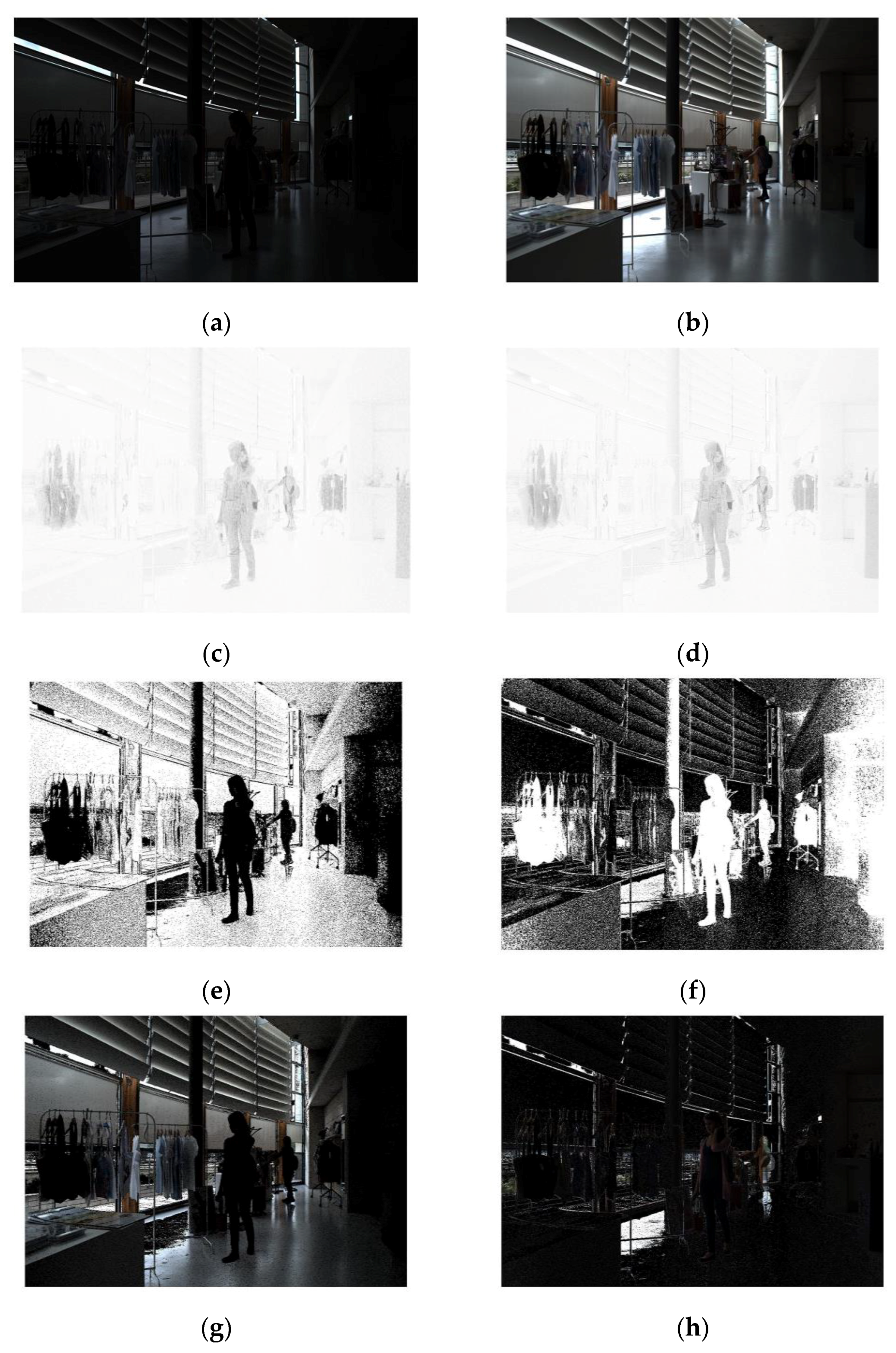
where {x,y} represent the pixel location in the image, J is the reference LDR image, while I is the image in which we are trying to find the pixels; i.e., the input LDR image. <.,.> represents the scalar or inner product between I and J. I and J are both three-dimensional vectors comprising RGB channels. The dot product between two aligned vectors—i.e., with a zero angle between them—is equal to the product of their magnitudes. This means that for perfectly aligned vectors I and J, their dot product will be ‖I‖ ‖J‖, where the symbol ‖.‖, represents the L2-norm. If the two vectors I and J are aligned, the above given ratio between <I, J>/‖I‖ ‖J‖ will become 1. The cosine inverse of 1 will result in the ideal value of SAM = 0. Thus, two identical pixels will result in a SAM value equal to zero. This implies that the lower the value of SAM, the more closely matched the pixels. Since we have to classify the pixels as static or moving, we experimented and identified a suitable threshold. This was done by normalizing the SAM map between 0 and 1. SAM map normalization was achieved by dividing each pixel in the map with the maximum SAM value in that map. The normalized map can be scaled in the range 0–255 by multiplying it by 255. Next, the map is subtracted from 255 to make static regions close to 255 and regions with motion equal to zero. This is done so that when the map is multiplied with the input LDR image (exposure image), the regions with motion are removed from the it. To get a binary map, all values less than 240 are considered to have motion and are made zero while the rest of the values are made 1. This thresholding results in a binary map per pixel. For visualization, the reference image is shown in Figure 1a, with the input LDR image (exposure image)—i.e., the image in which motion pixels need to be identified— shown in Figure 1b, and the SAM map between them, scaled to the range 0–255, shown in Figure 1c.

3.2. Deep Convolutional Neural Network Based Denoising

SAM successfully identifies the pixels which have moved between two images. This is evident from the fact that the girl can be seen at the center of the image in Figure 1a and in the right corner in Figure 1b. In the SAM map of Figure 1c, both regions appear dark, indicating movement. However, looking closely at these regions, it is observable that these regions contain noise; i.e., some pixels appear dark while other bright. This noise can be removed from the map using denoising. The deep convolutional neural network (DnCNN)-based denoiser proposed by Zhang et al. [33] is an ideal choice for this purpose. This is because of the ability of residual neural networks to effectively estimate a clean image from a noisy observation and achieve better performance as compared to state-of-the-art denoising algorithms. The MATLAB implementation used for this work was made available by the authors of the paper. The SAM map after denoising is shown in Figure 1d. Looking at the dark regions, it is clear that noise in those regions has been reduced. If this noise was not removed, the resultant HDR image will have a large number of small holes in it.

3.3. Reconstruction of Input LDR Images

Once the SAM map has been denoised, the last step in the process of identification of ghost pixels is setting a threshold to binarize the image. We tested multiple threshold values and evaluated the results both subjectively and objectively. Our experiments suggested that a threshold value of 240 resulted in HDR images with both high subjective quality and objective scores. The binary SAM map obtained after thresholding is shown in Figure 1e. This binary map shall be used to obtain the pixels of the input LDR image which do not exhibit motion. The resultant image is shown in Figure 1g. The pixels that exhibit motion appear dark in this image and, if passed to the HDR generation algorithm, this will result in an image with unnatural intensity variations or black regions. To fix this issue, these pixels are replaced by the pixels from the reference image. This can be done by taking the inverse of the binary SAM map and multiplying the inverted binary SAM map with the reference image. The resultant image is shown in Figure 1h. The complementary information obtained from the input and reference image is combined into a single image. This image is a processed form of input LDR image with no moving pixels with respect to the reference image and hence can be used for generation of an HDR image.

3.4. Generation of HDR Image

Images obtained after deghosting can be used for the generation of HDR images. Any HDR image generation method may be used; however, we have used the ‘makehdr’ method available in Matlab [35]. An advantage of the proposed method is its focus on deghosting rather than HDR image generation. Since the output of the proposed algorithm is a set of processed LDR images, they may be used as inputs to any HDR image generation method. Different HDR image generation methods result in images with different dynamic ranges and, hence, deghosting may be utilized with the existing method.
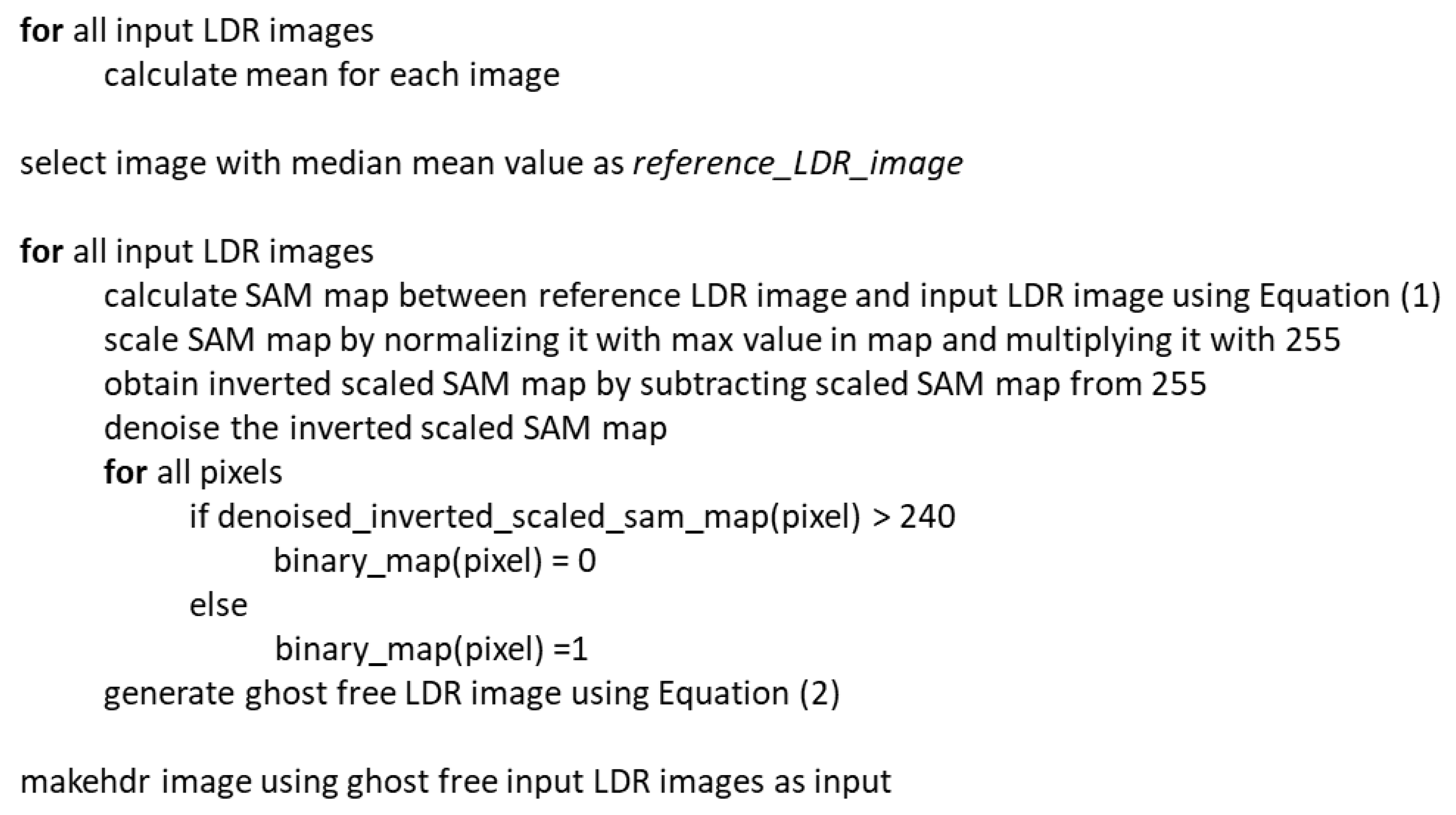
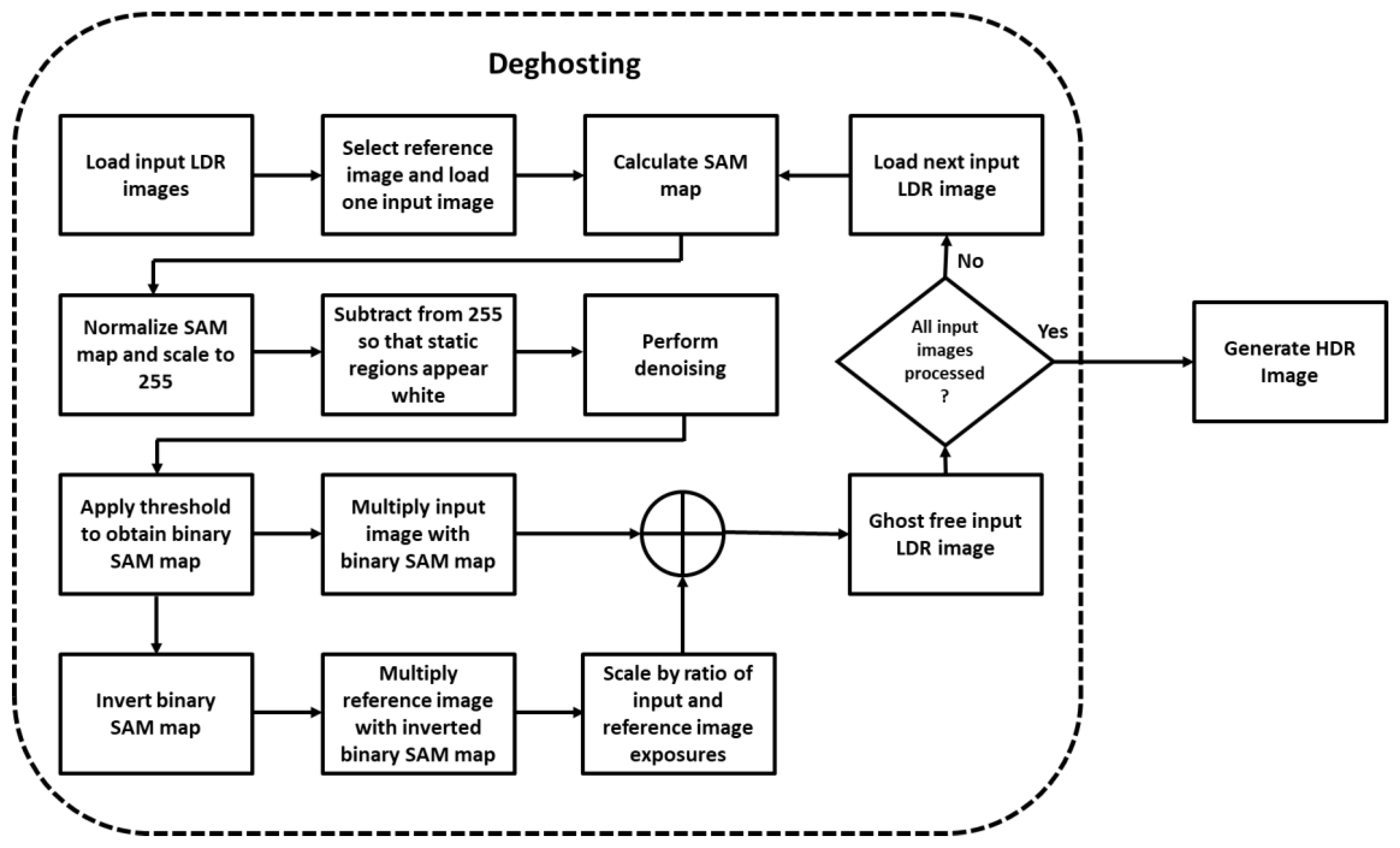
The summary of the proposed deghosting algorithm in correspondence with Figure 2 is presented below while the pseudo code of the algorithm is presented in Figure 3.
  • Load LDR images for processing;
  • From a given set of LDR images (LDRI) identify the reference image (refLDRI). The reference image may be selected by calculating the mean intensity of each channel and then for the image and selecting the image with the median average intensity value. An example of a reference image is shown in Figure 1a;
  • Next, calculate the SAM map between each LDR image and the reference image. This results in a SAM map per image;
  • Scale each SAM map by normalizing it with the maximum SAM value in the map. Next, scale it between 0 and 255 by multiplying the normalized map with 255;
  • In the scaled SAM map, static pixels have a lower value while pixels with movement have higher intensities. To invert them, subtract the scaled SAM map from 255. Now, the dark regions represent pixels with motion. The inverted scaled SAM map is shown in Figure 1c;
  • The inverted scaled SAM map has noise that can be reduced by using the denoising algorithm proposed by Zhang et al. [33]. This results in a denoised-inverted-scaled SAM map as shown in Figure 1d;
  • To obtain a binary representation of denoised-inverted-scaled SAM map (bin_map), we set a threshold of 240. All pixels below 240 are considered to represent motion. The resultant binary SAM map for an input LDR image is shown in Figure 1e;
  • Multiply the input LDR image with the binary SAM map to obtain the portion of the input LDR image without motion. The resultant image is shown in Figure 1g;
  • For the missing parts of the input image, we invert the binary SAM map as shown in Figure 1f;
  • Next, multiply the reference LDR image with the inverted binary SAM map to get the missing parts of Figure 1g;
  • Scale the image obtained in the previous step by multiplying it by the ratio in the average intensity values of the input and reference images. If the exposure settings are known, then scale it by the ratio of the exposure values. The resultant image is shown in Figure 1h;
  • Finally, add the two images shown in Figure 1g,h to obtain the image that shall be passed to the HDR image generation algorithm.
Steps 8 to 12 can be represented mathematically as:
L D R I d e - g h o s t e d = L D R I b i n _ m a p + [ ( 1 b i n _ m a p ) r e f L D R I ] exp o s u r e ( L D R I ) exp o s u r e ( r e f L D R I )
Repeat the above given steps from step 3 to step 12 for all images of the LDR cube.

4. Experimentation and Results

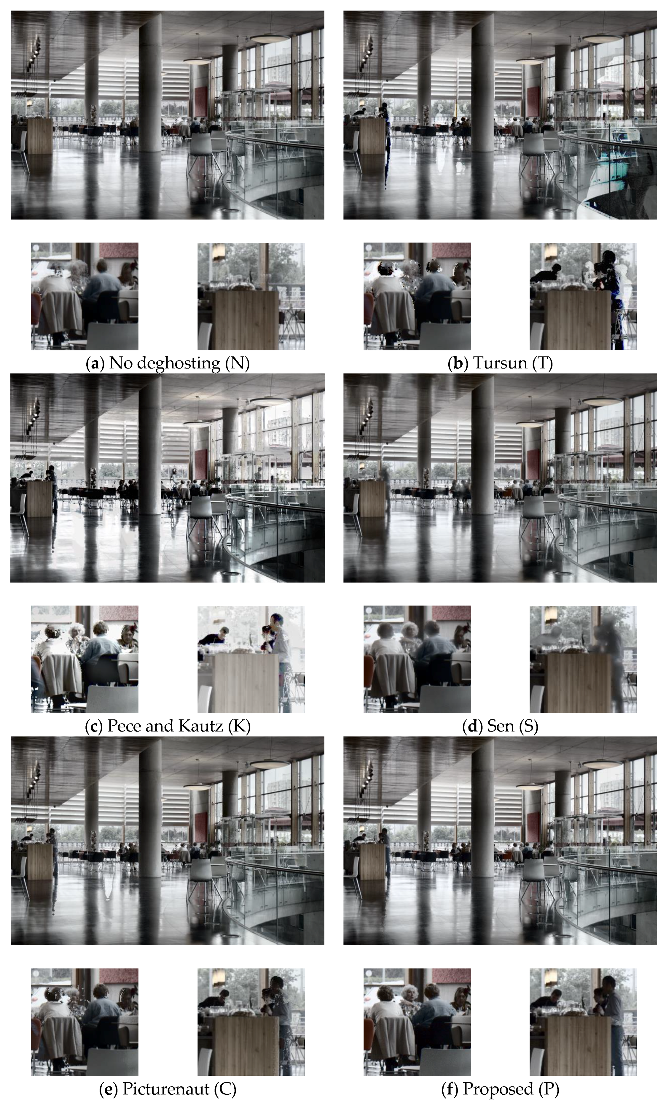
To assess the performance of the proposed deghosting method, we used the dataset provided by Tursun et al. [1]. The dataset comprises of 10 LDR image sets, with each set containing 9 images captured using an increasing exposure time setting. The data set images are globally registered; i.e., the camera stays still for the set of images, although the objects are not static. The ten images are titled “Cafe, Candles, Fastcars, Flag, Gallery1, Gallery2, Libraryside, Shop1, Shop2, PeopleWalking”. The results for four of the ten images are presented in Figure 4, Figure 5, Figure 6 and Figure 7 for subjective comparison and quality assessment, while the objective quality assessment results for all ten images are presented in Table 2.
For objective quality assessment, we employed Tursun et al.’s [36] deghosting quality assessment measures. These indices were selected because they provide separate assessments for the dynamic range of HDR images and errors in magnitude and direction of gradients. These indices can be combined and presented as a unified score; however, keeping them separate helps relate them to subjective evaluation. To compare the results of the proposed algorithm (P), it has been compared with five existing methods. The methods have been selected based upon their performance, as determined in [1,37], and their readily available implementations. The proposed method has been compared to no deghosting (N), deghosting methods proposed by Tursun et al. [1] (T), Pece and Kautz (K) [14], Sen et al. (S) [23] and with the deghosting option available in Picturenaut software version 3.2 [38] (C). The implementation of [23] was obtained from the authors’ website, while the implementation of [14] was made available by the authors of [39]. All experimentation was done using MATLAB R2018a. With the exception of the results of Pece and Kautz (K) and Picturenaut (C), all HDR images were generated using the ‘makehdr’ function of MATLAB. For these results, deghosting was done as proposed by their respective algorithms in MATLAB, and then the ‘makehdr’ function was used to construct the HDR image. To visualize the results, all HDR images were tone mapped using the tone mapping function provided in MATLAB. Quality assessment was done using the input LDR images and the HDR results. Alongside quality, we also compared the time for generation of HDR images by these methods and observed that, on average, (N) required 2.9 s, (C) required 8.7 s, (T) required 10.2 s, (K) required 17.1 s, (P) required 25.3 s and (S) required more than 4 min.

4.1. Subjective Assessment

To perform a subjective comparison of the proposed deghosting algorithm, we visually inspected the output of HDR images (N, T, K, S, C and P) using tone mapping provided in MATLAB. The same tone mapping method is used to remove any inconsistencies that may be caused by using different tone mapping operators. The results for the ‘Cafe’ image are presented in Figure 4. Looking at the no-deghosting (N) result in Figure 4a, it appears as if the image does not suffer from ghost artifacts. However, a zoom of the image clearly shows that the heads of people in the image appear blurred. The result produced by Tursun et al.’s [1] algorithm has ghost artifacts in it. This is shown as Figure 4b and is further highlighted in the zoomed images. The results obtained by the Pece and Kautz method (K) perform better at deghosting but suffer from incomplete objects, evident from the objects in Figure 4c. The result obtained using Sen et al.’s method appears to produce better deghosting, and objects do not have holes in them. However, the pixels demonstrating motion are not sharp, compared to the proposed method. Usage of Picturenaut software with the deghosting option results in an HDR image in which heads of both the ladies are clearly visible, but the image still contains noise and suffers from incomplete objects, as shown in Figure 4e. Figure 4f presents the results of the proposed deghosting method, and the two ladies can be clearly seen in the figure. Similarly, the couple standing next to the bar is visible in the image without deghosting. Thus, the best result is obtained using the proposed method.
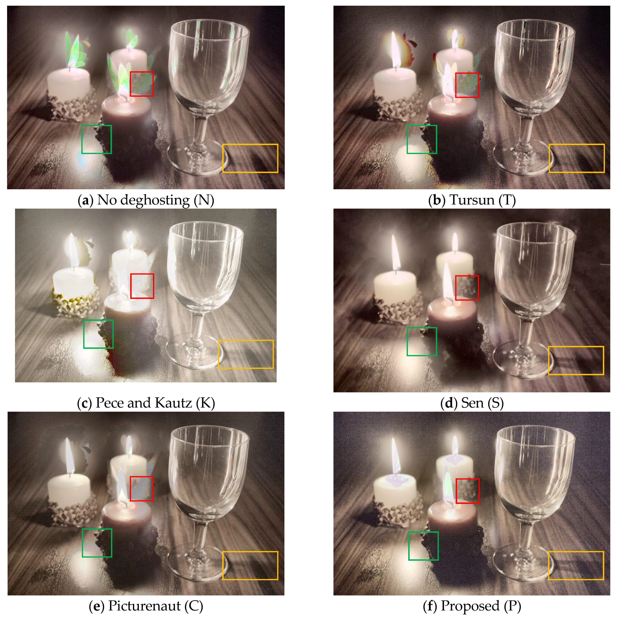
The image set titled ‘Candles’ is challenging as input LDR images not only have movement but also have illumination variation. A red box is used to highlight the difference between the compared algorithms. Except for the result shown in Figure 5d,f, all the other images suffer from ghosting as the texture of the candle stand is not visible. A green box is used to demonstrate both deghosting and the dynamic range of the resultant images. Comparing Figure 5d, obtained using Sen et al.’s deghosting, and Figure 5f, obtained using proposed deghosting, it can be observed that the image presented in Figure 5f is slightly clearer and sharper compared to the image in Figure 5d. Looking at the yellow rectangles it can be observed that the shadow of the glass is hardly visible in images obtained by no deghosting, Tursun et al.’s method, Pece and Kautz’s method and Picturenaut software. The shadow of the glass can be clearly seen in Figure 5d,f, thus indicating that they may have a higher dynamic range compared to the other images. However, looking at the overall quality of these two images, Figure 5f seems to have slightly higher noise in dark regions. Also, the flame and candle wick are more visible in the result obtained by Sen et al.’s method.
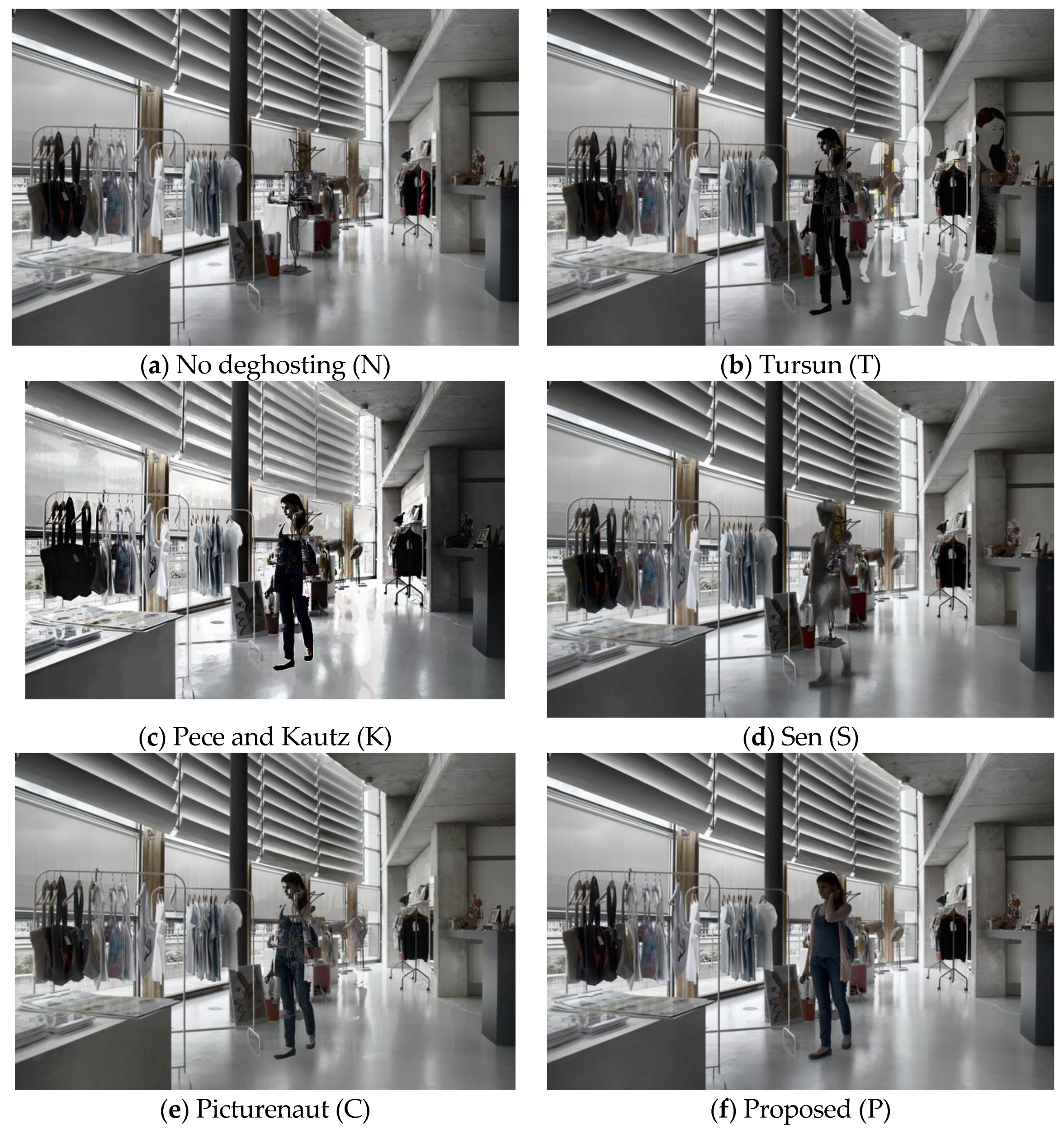
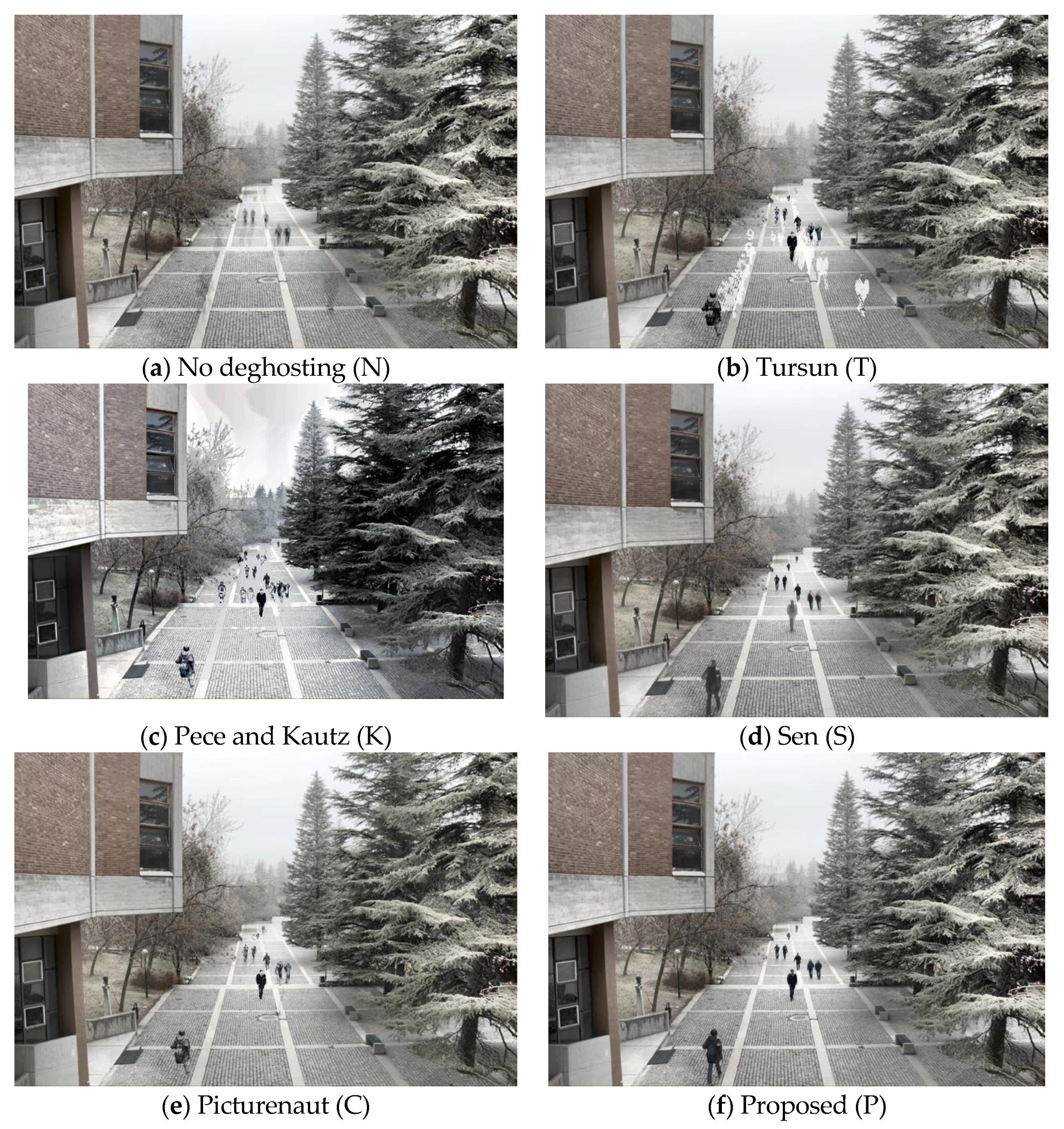
Observing the results presented in Figure 6 and Figure 7 it is clear that the best deghosting results are produced by the proposed method. It may appear that there are no ghost artifacts in Figure 6a; however, a closer inspection of the image reveals a marginally visible silhouette in various parts of the image. These ghost artifacts are clearer in Figure 7a. Ghost artifacts are clearly visible in Figure 6b and Figure 7b, obtained using Tursun et al.’s method [1]. The result obtained by using Picturenaut software, in Figure 6e and Figure 7e, contain both ghost artifacts and holes. The ghost artifact seen in Figure 6e seems to have reduced color information, whereas the ghost artifacts in Figure 7e are clearly visible against a bright background. Methods (K) and (S) seem to present similar issues with deghosting for the person in the ‘Shop2’ image. The person does not appear complete and the colors do not appear natural. In this regard, the proposed method presents the best result among the compared methods, as shown in Figure 7f. Similarly, for the image in which people are walking, the proposed method seems to perform appropriately, removing ghosting, and making the person in the center of the image appear clearly. Sen et al.’s method produces a nearly similar result for the rest of the image; however, the person in the center of the image is not clear and appears blurred.
A subjective assessment of the results clearly suggests that our proposed method outperforms the prior state-of-the-art it is being compared with. However, subjective assessment is user dependent and, therefore, it is better to assess the quality objectively. In this regard, we have compared the quality of the proposed method using the quantitative measures: dynamic range, difference in magnitude of gradient and difference in direction of gradient, as proposed by Tursun et al. in [36].

4.2. Objective Assessment

In [36], the authors proposed the calculation of dynamic range of non-static pixels. This was proposed to avoid the influence of static regions, as dynamic range from them could make the dynamic range contribution from non-static regions insignificant. The authors proposed estimation of dynamic regions DR(p) by observing if DR’(p) is greater than a tolerance threshold ‘τ = 0.3’. The authors estimated the threshold value by experimentation and defined DR’(p) as
D R ( p ) = max c { r , g , b } , n { 1 , , N 1 } h ( E n c ( p ) , E n + 1 c ( p ) ) W n , n + 1 ( p )
where ‘p’ represents the pixel location, ‘c’ the RGB channel, ‘En’ the input LDR image (exposure image), ‘h’ is a function returning the Euclidean distance between En and En+1, and Wn,n+1 attenuates the pixels which are under- or over-exposed.
The quality of dynamic range is finally calculated using
Q D = log 10 I ( p 99 % ) log 10 I ( p 1 % )
where ‘QD’ represents the dynamic range quality measure, ‘I’ represents the HDR image and where 1% of pixels are dropped from the calculations to obtain a stable result [1]. The results of dynamic range are presented in Table 1. The higher the dynamic range, the better the quality of the HDR image. For clarity, the best values for each image are presented in green. From the table, it is clear that the dynamic range of HDR image obtained by using proposed deghosting is better than the dynamic range of HDR image generated without deghosting, thus highlighting that the proposed deghosting algorithm does not affect the dynamic range of HDR image. It is important to note the dynamic range of the HDR image after deghosting, because if only the reference image is selected and all other images are discarded, then there will be no ghost artifacts in the HDR image. However, the dynamic range of the HDR image would be severely reduced. This is not the case with the proposed method, as is evident from the results presented in Table 1.
Comparing the dynamic range of HDR images obtained using the method proposed by Sen et al. [23], it can be observed from Table 1 that the dynamic range of HDR image of the ‘Flag’ and ‘Gallery1’ data sets is slightly higher for Sen as compared to the proposed method. One possible reason for this could be that these test images are relatively bright as compared to other images in the dataset and Sens’ method works better on brighter images as compared to the proposed method.
In [36], the authors also hypothesize that neither should an HDR image have gradients that are not present in the LDR input images, nor should it be missing gradients that are present in the LDR images. To assess this, the authors propose to calculate the change in magnitude of gradients as:
Q G m a g ( p ) = min n | E n ¯ 2 I ¯ 2 I ( p ) 2 E n ( p ) 2 | max { E n ¯ 2 I ¯ 2 I ( p ) 2 , E n ( p ) 2 }
where, ‘∇E’ represents the sobel operator-based gradient map of input LDR (exposure) image while ‘∇I’ represents the gradient map for the HDR image. The ‘’ symbol indicates a mean value. The denominator term ensures that the result is normalized to the range [0,1]. Similar to gradient magnitude quality assessment, the authors propose the calculation of the gradient orientation quality using the following equation:
Q G d i r ( p ) = min n | [ ( θ I ( p ) θ n ( p ) + π ) mod 2 π ] π | / π
where they propose the measurement of the minimum angle between the directions of gradient vectors and divide the result by ‘π’, normalizing the result to the range [0,1]. The authors proposed to use 5-level multi-resolution pyramid for gradient magnitude and orientation calculations.
The quantitative analysis of gradient magnitude and direction indicates that the proposed method (P) generates the best results. The results are presented in Table 2, where each column represents the quality index for each of the tested methods. It is clear that results for the proposed scheme are always the best and hence appear in green color. The only exception to this is for the ‘Fastcars’ image, where the method proposed by Sen et al. [23] outperforms the proposed method. For all other images, the proposed method (P) has a lower gradient magnitude and direction difference as compared to the rest of the methods. This is in accordance with the subjective assessment of results, where the proposed method removes ghost artifacts better than other methods. The quality assessment measures QGmag and QGdir require that no artifacts appear in the HDR image and also that the gradients of input exposure images should be represented in the HDR image. The quantitative results indicate that this is best performed by the proposed method. This can be described by visually looking at the results presented in Figure 7. From Figure 7b, it can be seen that there are approximately seven single people or couples walking, as their tracks are visible. The gradient magnitude difference of (K) is the highest, and correspondingly the most artifacts appear in the image presented as Figure 7c. Both (C) and (S) have holes or blurred individuals, and hence they have a higher gradient magnitude difference value compared to the reference result (P). Although the no deghosting (N) gradient magnitude difference results are closer to the proposed method, it suffers from visual artifacts. It may have a lower value since it adheres to the condition of having the gradients of input LDR (exposure) images present in the HDR image.
Authors of [1] demonstrated high correlation between their proposed measures and existing state-of-the-art deghosting quality assessment methods. Hence, it may be inferred that testing the methods presented in this work will lead to similar results with other quality assessment methods.
5. Conclusions

In this paper, a deghosting method based on the use of SAM is proposed for the generation of HDR images. The proposed method is computationally efficient and may be used even if the exposure values of the LDR image set are not known. The proposed method was compared to the existing deghosting methods, both subjectively and objectively, using an existing image database and quality assessment indices. The proposed method outperformed the tested methods for most indices and produced visually pleasing and artifact-free results, as compared to the other methods. A multi-resolution analysis-based approach may be adopted to further improve the quality of the proposed method.

Conflicts of Interest

The authors declare no conflict of interest.

References

  1. Tursun, O.K.; Akyuz, A.O.; Erdem, A.; Erdem, E. The state of the art in HDR deghosting: A survey and evaluation. Comput. Gr. Forum 2015, 34, 683–707. [Google Scholar] [CrossRef]
  2. Ward, G. Fast, robust image registration for compositing high dynamic range photographs from hand-held exposures. J. Gr. Tools 2003, 8, 17–30. [Google Scholar] [CrossRef]
  3. Cerman, L.; Hlavac, V. Exposure time estimation for high dynamic range imaging with hand held cameras. Available online: http://citeseerx.ist.psu.edu/viewdoc/download?doi=10.1.1.92.3979&rep=rep1&type=pdf (accessed on 1 February 2019).
  4. Gevrekci, M.; Gunturk, B.K. On geometric and photometric registration of images. In Proceedings of the 2007 IEEE International Conference on Acoustics, Speech and Signal Processing—ICASSP ‘07, Honolulu, HI, USA, 15–20 April 2007. [Google Scholar]
  5. Tomaszewska, A.; Mantiuk, R. Image registration for multi-exposure high dynamic range image acquisition. In Proceedings of the 15th International Conference in Central Europe on Computer Graphics, Visualization and Computer Vision 2007, University of West Bohemia, Pilsen, Czech Republic, 29 January–1 February 2007. [Google Scholar]
  6. Im, J.; Jang, S.; Lee, S.; Paik, J. Geometrical transformation-based ghost artifacts removing for high dynamic range images. In Proceedings of the 18th IEEE International Conference on Image Processing, Brussels, Belgium, 11–14 September 2011. [Google Scholar]
  7. Akyuz, A.O. Photographically guided alignment for HDR images. In Eurographics (Areas Papers); The Eurographics Association: Geneve, Switzerland, 2011; pp. 73–74. [Google Scholar]
  8. Khan, E.; Akyuz, A.O.; Reinhard, E. Ghost removal in high dynamic range images. In Proceedings of the 13th IEEE Int. Conf. on Image Processing (ICIP), Atlanta, GA, USA, 8–11 October 2006; pp. 2005–2008. [Google Scholar]
  9. Granados, M.; Seidel, H.P.; Lensch, H. Background estimation from non-time sequence images. In Proceedings of the Graphics Interface 2008, Windsor, ON, Canada, 28–30 May 2008. [Google Scholar]
  10. Silk, S.; Lang, J. Fast high dynamic range image deghosting for arbitrary scene motion. In Proceedings of the Graphics Interface 2012, Toronto, ON, Canada, 28–30 May 2012. [Google Scholar]
  11. Zhang, W.; Cham, W.K. Gradient-directed multi-exposure composition. Trans. Image Process. IEEE 2012, 21, 2318–2323. [Google Scholar] [CrossRef] [PubMed]
  12. Kao, W.C.; Hsu, C.; Chen, L.Y.; Kao, C.C.; Chen, S.H. Integrating image fusion and motion stabilization for capturing still images in high dynamic range scenes. IEEE Trans. Consum. Electron. 2006, 52, 735–741. [Google Scholar]
  13. Jacobs, K.; Loscos, C.; Ward, G. Automatic high dynamic range image generation for dynamic scenes. IEEE Comput. Gr. Appl. 2008, 28, 84–93. [Google Scholar] [CrossRef]
  14. Pece, F.; Kautz, J. Bitmap Movement Detection: HDR for Dynamic Scenes. In Proceedings of the 2010 Conference on Visual Media Production, London, UK, 17–18 November 2010. [Google Scholar]
  15. Lee, D.K.; Park, R.H.; Chang, S. Improved histogram based ghost removal in exposure fusion for high dynamic range images. In Proceedings of the 2011 IEEE 15th International Symposium on Consumer Electronics (ISCE), Singapore, 14–17 June 2011. [Google Scholar]
  16. Khan, I.R.; Khan, M.M. A simple de-ghosting algorithm for HDRI. In Proceedings of the SIGGRAPH ASIA 2016 Posters, Macau, China, 5–8 December 2016. [Google Scholar]
  17. Shim, S.O.; Khan, I.R. Removal of ghosting artefacts in HDRI using intensity scaling cue. In Proceedings of the SIGGRAPH Asia 2017 Technical Briefs, Bangkok, Thailand, 27–30 November 2017. [Google Scholar]
  18. Liu, Y.; Wang, Z. Dense SIFT for ghost-free multi-exposure fusion. J. V. Commun. Image Represent. 2015, 31, 208–224. [Google Scholar] [CrossRef]
  19. Zhang, W.; Hu, S.; Liu, K. Patch-based correlation for deghosting in exposure. Inf. Sci. 2017, 415, 19–27. [Google Scholar] [CrossRef]
  20. Chang, M.; Feng, H.; Xu, Z.; Li, Q. Robust ghost-free multiexposure fusion for dynamic scenes. J. Electron. Imaging 2018, 27, 033023. [Google Scholar] [CrossRef]
  21. Zhang, W.; Hu, S.; Liu, K.; Yao, J. Motion-free exposure fusion based on inter-consistency and intra-consistency. Inf. Sci. 2017, 376, 190–201. [Google Scholar] [CrossRef]
  22. Raman, S.; Kumar, V.; Chaudhuri, S. Blind deghosting for automatic multi-exposure compositing. In Proceedings of the ACM SIGGRAPH ASIA 2009 Posters, Yokohama, Japan, 16–19 December 2009. [Google Scholar]
  23. Sen, P.; Kalantari, N.K.; Yaesoubi, M.; Drabi, S.; Goldman, D.B.; Shechtman, E. Robust patch-based hdr reconstruction of dynamic scenes. Available online: https://www.ece.ucsb.edu/~psen/Papers/SIGASIA12_HDR_PatchBasedReconstruction_LoRes.pdf (accessed on 2 February 2019).
  24. Li, Z.; Rahardja, S.; Zhu, Z.; Xie, S.; Wu, S. Movement detection for the synthesis of high dynamic range images. In Proceedings of the 2010 IEEE International Conference on Image Processing, Hong Kong, China, 26–29 September 2010. [Google Scholar]
  25. Srikantha, A.; Sidibe, D.; Meriaudeau, F. An SVD-based approach for ghost detection and removal in high dynamic range images. In Proceedings of the 21st International Conference on Pattern Recognition (ICPR2012), Tsukuba, Japan, 11–15 November 2012. [Google Scholar]
  26. Sung, H.S.; Park, R.H.; Lee, D.K.; Chang, S. Feature based ghost removal in high dynamic range imaging. Available online: https://pdfs.semanticscholar.org/b662/cc635f0fdac42c78df88d2c47281958387a8.pdf (accessed on 1 February 2019).
  27. Wang, C.; Tu, C. An exposure fusion approach without ghost for dynamic scenes. In Proceedings of the 2013 6th International Congress on Image and Signal Processing (CISP), Hangzhou, China, 16–18 December 2013. [Google Scholar]
  28. Hossain, I.; Gunturk, B.K. High dynamic range imaging of non-static scenes. Digit. Photogr. VII 2011, 7876, 78760. [Google Scholar]
  29. Jinno, T.; Okuda, M. Multiple exposure fusion for high dynamic range image acquisition. IEEE Trans. Image Process. 2012, 21, 358–365. [Google Scholar] [CrossRef] [PubMed]
  30. Hafner, D.; Demetz, O.; Weickert, J. Simultaneous HDR and optic flow computation. In Proceedings of the 22nd International Conference on Pattern Recognition, Stockholm, Sweden, 24–28 August 2014. [Google Scholar]
  31. Alparone, L.; Baronti, S.; Garzelli, A.; Nencini, F. Landsat ETM+ and SAR image fusion based on generalized intensity modulation. IEEE Trans. Geosci. Remote Sens. 2004, 42, 2832–2839. [Google Scholar] [CrossRef]
  32. Petropoulous, G.P.; Vadrevu, K.P.; Xanthopoulos, G.; Karantounias, G.; Scholze, M. A comparison of spectral angle mapper and artificial neural network classifiers combined with Landsat TM imagery analysis for obtaining burnt area mapping. Sensors 2010, 10, 1967–1985. [Google Scholar] [CrossRef] [PubMed]
  33. Zhang, K.; Zuo, W.; Chen, Y.; Meng, D.; Zhang, L. Beyond a Gaussian Denoiser: Residual learning of deep CNN for image denoising. IEEE Trans. Image Process. 2017, 26, 3142–3155. [Google Scholar] [CrossRef] [PubMed]
  34. Reinhard, E.; Ward, G.; Debevec, P.; Pattanaik, S.; Heidrich, W.; Myszkowski, K. High Dynamic Range Imaging, 2nd ed.; Morgan Kaufmann: Burlington, CA, USA, 2010. [Google Scholar]
  35. MATLAB-Mathworks. Available online: https://www.mathworks.com/products/matlab.html (accessed on 30 December 2018).
  36. Tursun, O.T.; Akyuz, A.O.; Erdem, A.; Erdem, E. An objective deghosting quality metric for HDR images. Eurographics 2016, 35, 2. [Google Scholar] [CrossRef]
  37. Hadziabdic, K.K.; Telalovic, J.H.; Mantiuk, R.K. Assessment of multi-exposure HDR image deghosting methods. Comput. Gr. 2017, 63, 1–17. [Google Scholar] [CrossRef]
  38. Picturenaut. Available online: http://hdrlabs.com/picturenaut/ (accessed on 30 December 2018).
  39. Banterle, F.; Artusi, A.; Debattista, K.; Chalmers, A. Advanced High Dynamic Range Imaging: Theory and Practice, 2nd ed.; CRC Press: Boca Raton, FL, USA, 2017. [Google Scholar]
Figure 1. Images at different stages of deghosting. (a) Reference low dynamic range (LDR) image; (b) input LDR image; (c) spectral angle mapper (SAM) map after inversion; (d) SAM map after denoising; (e) binary map obtained after thresholding the denoised SAM map; (f) inverted denoised binary SAM map; (g) input image after multiplication with the denoised binary SAM map; (h) reference image after multiplication with the inverted denoised binary SAM map.
Computers 08 00015 g001
Figure 2. Block diagram of the proposed deghosting methodology.
Computers 08 00015 g002
Figure 3. Pseudocode for the proposed algorithm.
Computers 08 00015 g003
Figure 4. Tone mapped results of ‘Cafe’ high dynamic range (HDR) images obtained by (a) no deghosting, (b) Tursun et al., [1] (c) Pece and Kautz, [14] (d) Sen et al., [23], (e) Picturenaut software, and (f) the proposed method. Zoomed regions of results are also shown to demonstrate the deghosting capability of each method.
Computers 08 00015 g004
Figure 5. Tone mapped results of ‘Candles’ HDR images obtained by (a) no deghosting, (b) Tursun et al., [1] (c) Pece and Kautz, [14] (d) Sen et al., [23], (e) Picturenaut software, and (f) the proposed method.
Computers 08 00015 g005
Figure 6. Tone mapped results of ‘Shop2’ HDR images obtained by (a) no deghosting, (b) Tursun et al., [1] (c) Pece and Kautz, [14] (d) Sen et al., [23], (e) Picturenaut software, and (f) the proposed method.
Computers 08 00015 g006
Figure 7. Tone mapped results of ‘WalkingPeople HDR images obtained by (a) no deghosting, (b) Tursun et al., [1] (c) Pece and Kautz, [14] (d) Sen et al., [23], (e) Picturenaut software, and (f) the proposed method.
Computers 08 00015 g007
Table 1. Comparison of the dynamic range of the HDR images obtained using the proposed deghosting method and no deghosting.
CafeCandlesFastCarsFlagGallery1Gallery2Library SideShop1Shop2People Walking
No deghosting (N)2.422.870.901.621.601.992.052.152.021.12
Proposed deghosting (P)2.5012.911.341.621.702.082.682.412.461.53
Sen deghosting (S)2.462.851.192.541.762.052.122.232.161.49
1 Values in green indicate the best result.
Table 2. The results of the objective quality assessments measures for the images of the dataset.
Image SetGradient Magnitude DifferenceGradient Direction Difference
NTKSCPNTKSCP
Cafe0.0070.2080.0360.0250.5540.0050.0070.0260.0260.0170.0260.007
Candles0.0630.2380.0270.1220.7520.0090.0480.0500.0140.0460.0510.007
FastCars0.0270.1770.0050.0050.0540.0110.0200.0430.0070.0040.0230.013
Flag0.0070.0160.3470.2530.1180.0020.0090.0140.1050.0190.0150.007
Gallery10.0020.0040.1150.0050.2810.0010.0050.0080.0680.0040.0140.004
Gallery20.0340.4740.0440.0490.7250.0020.0090.0160.0250.0100.0140.004
LibrarySide0.0100.0180.0020.0120.5940.0010.0130.0190.0020.0120.0310.002
Shop10.0070.0360.0670.0280.4400.0080.0080.0260.0250.0160.0300.009
Shop20.0070.0480.0530.0430.4560.0050.0070.0320.0340.0210.0240.006
PeopleWalking0.0030.0120.0490.0150.0120.0020.0040.0120.0260.0170.0160.004