
Article

Stereo-Based Single-Shot Hand-to-Eye Calibration for Robot Arms

by
Pushkar Kadam
1,*,
Gu Fang
1,*,
Farshid Amirabdollahian
2,
Ju Jia Zou
1 and
Patrick Holthaus
2
1
Centre for Advanced Manufacturing Technology, School of Engineering, Design and Built Environment, Western Sydney University, Locked Bag 1797, Penrith, NSW 2751, Australia
2
Robotics Research Group, University of Hertfordshire, Hatfield AL10 9AB, UK
*
Authors to whom correspondence should be addressed.
Computers 2026, 15(1), 53; https://doi.org/10.3390/computers15010053
Submission received: 14 December 2025 / Revised: 8 January 2026 / Accepted: 11 January 2026 / Published: 13 January 2026
(This article belongs to the Special Issue Advanced Human–Robot Interaction 2026)

Abstract

Robot hand-to-eye calibration is a necessary process for a robot arm to perceive and interact with its environment. Past approaches required collecting multiple images using a calibration board placed at different locations relative to the robot. When the robot or camera is displaced from its calibrated position, hand–eye calibration must be redone using the same tedious process. In this research, we developed a novel method that uses a semi-automatic process to perform hand-to-eye calibration with a stereo camera, generating a transformation matrix from the world to the camera coordinate frame from a single image. We use a robot-pointer tool attached to the robot’s end-effector to manually establish a relationship between the world and the robot coordinate frame. Then, we establish the relationship between the camera and the robot using a transformation matrix that maps points observed in the stereo image frame from two-dimensional space to the robot’s three-dimensional coordinate frame. Our analysis of the stereo calibration showed a reprojection error of 0.26 pixels. An evaluation metric was developed to test the camera-to-robot transformation matrix, and the experimental results showed median root mean square errors of less than 1 mm in the x and y directions and less than 2 mm in the z directions in the robot coordinate frame. The results show that, with this work, we contribute a hand-to-eye calibration method that uses three non-collinear points in a single stereo image to map camera-to-robot coordinate-frame transformations.

1. Introduction

Vision sensors in robotic systems enable robots to perceive and interact with their environment. Vision-perception-enabled robots have several applications across different industries. Computer vision is important to deal with a dynamic workspace with many moving objects and the presence of humans [1]. Various types of computer vision-based robotic systems have been developed for industries such as gesture recognition [2], healthcare [3,4], manufacturing [5,6], and domestic applications [7]. One of the main applications of computer vision in manufacturing is the use of a robot arm for operations such as object sorting [8,9,10] and welding [11,12,13]. These types of robot arms are often equipped with specialised end-effectors for specific applications [6,14,15]. Thus, different sensors such as SONAR, LIDAR, and vision provide the necessary inputs to the robot arm to perceive its environment to detect objects and autonomously plan a safe path to interact with them.
With the advent of Industry 5.0, humans share space with the robots, thereby giving rise to the use of collaborative robots (Cobots) [16,17]. The development of Cobots revolves around the principles of making robots easier to set up and program. The ability to set up the vision sensor for the robot to perceive its environment must be straightforward and require minimal effort to make robots more user-friendly. An important step in setting up a vision sensor is to enable the robot to perceive its environment relative to its own position via so-called hand-to-eye calibration [18]. Therefore, a straightforward, easy-to-implement robot hand-to-eye calibration method is required to enable the robot to perceive its environment.
While the applications of the vision-enabled robot arm vary, a common practice across them is hand–eye calibration. Furthermore, due to the dynamic nature of the work environment, there is a high risk of robot or camera displacement, requiring a fresh robot hand–eye calibration. Thus, it is essential to develop a practical robot hand–eye calibration method that is quick to perform and applicable across a wide range of applications.

1.1. Camera Calibration

A computer vision system in a robotics application helps a robot to perceive its environment. A computer vision system often comprises either a monocular [4], stereo [19,20], or RGB-D (Red, Green, Blue-Depth) [8,21]. An RGB (Red, Green, Blue) monocular camera lacks depth information; however, a stereo camera rig can be constructed using two monocular cameras. RGB-D cameras comprise an RGB channel and a Depth channel that generate a depth map using infrared light [14,22]. A stereo camera is often constructed to ensure that the image sensors of the left and right cameras remain precisely aligned. The development of robotic systems relies on a specific type of camera. Furthermore, it is essential to calibrate these cameras to accurately determine the positions of objects in the real world.
Camera calibration is the process of determining a camera’s intrinsic and extrinsic parameters [23]. Real-world object points are projected into the camera frame using the extrinsic parameters, and the points from the camera frame to the image plane are transformed using the intrinsic parameters. Camera calibration involves using known patterns, such as a chessboard, whose dimensions are known. The corners of the chessboard grid are treated as object points detected in the image plane, known as image points. The transformation matrix, known as the projection matrix, is computed by collecting a set of object and image points [24]. Furthermore, the distortion coefficient vector and rectification rotation matrix are computed, thereby removing errors due to lens distortion [23]. Once the optimal projection matrix is found, a point in 3D space can be projected onto a 2D image plane. However, in monocular camera calibration, depth information cannot be retrieved. Therefore, a stereo camera is required to obtain the depth of the object point in the camera frame.
The stereo calibration process involves computing the reprojection matrix that maps points from 2D image space to 3D camera space [23]. The stereo calibration process also involves using a calibration pattern such as a chessboard. The object points are identified in both the left and right images of the stereo pair, and disparity maps are computed using stereographic and triangulation principles [20,25]. The disparity values of the points help to find the depth of the points relative to the left camera frame of the stereo camera. A reprojection error less than one pixel is considered ideal for the application [23]. The stereo calibration process relies on carefully capturing the chessboard pattern, clearly visible in both the left and right image planes of the stereo camera. Therefore, stereo calibration is an essential first step that enables the robots to view objects in their workspace.

1.2. Robot Hand–Eye Calibration

Robot hand–eye calibration involves developing a transformation matrix that maps object points from the camera frame to the robot frame [26]. The robot hand–eye calibration process is divided into two categories: Hand-to-eye and Hand-in-eye. The robot hand-to-eye approach involves static positioning of both the camera and the robot base. In the hand-to-eye approach, a relationship is established between the robot arm base and the camera frame [27]. The robot hand-in-eye approach uses a camera mounted near the robot arm’s flange. In the hand-in-eye approach, the camera moves with the flange, and the relationship between the robot flange and the camera frame is established [18,26,28]. Each camera mounting approach has its benefits, and their calibration processes differ.
Robot hand–eye calibration has been widely studied and remains an active area of research. The standard apparatus in most techniques involves a camera, a robot arm, and a calibration pattern [18,26]. The robot hand-in-eye method involves mounting the camera at the last link of the robot and capturing images of the calibration pattern from different robot positions and orientations [28]. In a robot hand-in-eye configuration, the transformation from the camera to the flange is unknown, while those from the world to the camera and from the flange to the robot base are known. This leads to solving the equation of the form A X = X B , where X is the unknown computed [26,29]. Dual quaternions have also been used for hand–eye calibration, providing a simultaneous solution for rotation and translation using singular value decomposition (SVD) [18]. Another approach to hand–eye calibration involves measuring the robot’s position in the world frame and determining the relationship between the camera and the flange [28]. A straightforward method uses a stereo camera and a point cloud to capture the robot poses relative to the camera. Then it solves for the 12 unknown parameters of the transformation matrix [27]. Most of these methods rely on collecting multiple images or data points and use an iterative solution to compute the hand–eye transformation matrix. Therefore, there remains scope to develop methods that perform hand–eye calibration with minimal data collection.
The application of a vision system in a dynamic environment poses a risk to a calibrated hand–eye system. Due to the dynamic nature of the workspace, a displacement of the robot or camera will require a fresh calibration method [28]. With the current mounting process for the calibration pattern on the robot flange, additional work is required to unmount and remount the end-effector. For Cobot applications, a straightforward yet intuitive hand–eye calibration process is required to make the setup process more user-friendly. Therefore, in this research, we solve the hand-to-eye calibration problem by leveraging the stereo calibration depth detection process to compute the camera transformation matrix. Then, we attach a pointer to the robot gripper to compute displacement vectors that, using only three non-collinear points [28] and a single set of calibration data, yield the world-to-robot transformation matrix. Finally, we compute the camera-to-robot transformation matrix that solves the hand-to-eye calibration problem.

1.3. Contributions

In this paper, we address the problem of robot hand-to-eye transformation for a stereo camera mounted on a fixed stand facing the workbench and a 6-DoF (Degree of Freedom) robot arm. Section 2 outlines the stereo calibration and robot hand-to-eye calibration using a single-shot stereo image. Section 3 provides details of the experimental setup, computer, software tools, and evaluation metric used to test the developed methods. Section 4 presents both quantitative and qualitative evaluations to assess the robustness of the developed hand-to-eye methods. Section 5 provides a detailed discussion about the methods, the experimental evaluation, and the robustness of the practical implementation. With that, we make the following contribution to robot hand-to-eye calibration:
1.
A stereo calibration approach to live render the image points that ensures all the image points are mapped to the camera coordinate frame.
2.
An automated single-shot world-to-camera transformation method using the depth estimation from a stereo camera.
3.
A robot hand-to-eye calibration method that uses three non-collinear points from a single image and depth estimation from a stereo camera to compute the camera-to-robot transformation matrix.
4.
A practical method to evaluate the hand-to-eye calibration process using quantitative and qualitative evaluation.

2. Materials and Methods

In this section, we present a simple and practical method for robot hand-to-eye calibration. First, in Section 2.1, we perform stereo calibration for depth detection using a live rendering of image points to map the image points to the camera coordinate frame, leading to Contribution 1. Using depth information from the stereo camera, we derived the world-to-camera transformation matrix leading to Contribution 2 in Section 2.3. We measured the world coordinate with respect to the robot base using a pointer held by the robot gripper on a 6-DoF robot. The pointer tool helps identify the transformation from the world to the robot’s coordinate frame. Finally, in Section 2.5, a transformation matrix was derived that maps points from camera to robot coordinates, yielding the camera-to-robot transformation matrix in Contribution 3.

2.1. One-Off Stereo Calibration

Stereo calibration was performed using a chessboard pattern, where 3D points are mapped to the 2D image plane. This calibration is a one-off process for a new camera and does not need to be repeated. This chessboard pattern consists of m × n internal grid points on a rigid planar surface. The internal grid points are the corner points of the black squares that connect each other on the chessboard. The chessboard was held in front of the stereo camera so that the grid pattern is clearly visible in both the left and right image planes. Only images in which the chessboard is clearly visible, without motion blur, and within the field of view of both image planes at the same time were selected for calibration.
Multiple stereo images were captured by rotating and moving the chessboard to cover the entire image frames of both cameras of the stereo setup. The intrinsic parameters, along with the distortion coefficients and the extrinsic parameters, were computed for both left and right cameras using the methods described in [24,30]. Further, stereo calibration was performed that computes intrinsic parameters for each camera in the stereo and the extrinsic parameters between the two cameras [23]. These parameters are essential for rectifying the image for stereo matching and eliminating lens distortion. Furthermore, stereo matching was performed using Semi-Global Block Matching (SGBM) [31], which produces a disparity map. Therefore, the left camera in the stereo pair becomes the camera frame { C } , and all world points are viewed in this frame.
One of the important results of the stereo calibration process is to obtain the re-projection matrix Q R 4 × 4 expressed as
Q = 1 0 0 c x 0 1 0 c y 0 0 0 f 0 0 1 T x ( c x c x ) T x ,
where
  • c x and c y are the principal point’s x and y coordinates in the left image;
  • c x is the principal point’s x coordinate in the right image;
  • f is the focal length of the stereo cameras;
  • T x is the baseline, which is the distance between the left and right camera centres.
The parameters in Equation (1) refer to the position of the optical axis of the camera given by c x and c y . The focal length f indicates the distance from the lens of the camera to the image plane, and the baseline T x is the distance between the two optical axes of the stereo left and right camera planes.
Any given point at ( u , v ) in the image plane of the left camera and its corresponding disparity value d from the disparity map can be used to find the location of the point in the camera coordinates as
x ˜ y ˜ z ˜ w ˜ = Q · u v d 1 ,
where ( x , y , z ) = ( x ˜ w ˜ , y ˜ w ˜ , z ˜ w ˜ ) are the coordinates of a point in the camera frame { C } .

2.2. Coordinate System Nomenclature

The coordinate frames established in this method were set using the right-hand rule. Figure 1 shows the coordinate transformation model. The robot, world, pointer tool, and camera coordinate frames are represented in curly braces along with their respective transformation matrices. The following are the definitions of the coordinate frames and transformations useful to establish the relationship between different frames:
  • { C } : The camera coordinate frame obtained by stereo calibration and located at the left camera of the stereo camera.
  • { W } : The world coordinate frame established at the top left corner of the first object point of the inner grid of the chessboard.
  • { R } : The robot coordinate frame established at the base of the robot.
  • { P } : The pointer tool attached to the robot end-effector used for measuring the world coordinates with respect to the robot frame { R } .
  • T W C R 4 × 4 : A transformation matrix from the world frame { W } to the camera frame { C } .
  • T W R R 4 × 4 : A transformation matrix from the world frame { W } to the robot frame { R } .
  • T C R R 4 × 4 : A transformation matrix from the camera frame { C } to the robot frame { R } .

2.3. World-to-Camera Transformation

The world to camera transformation matrix T W C R 4 × 4 was formed using a rotation matrix R W C R 3 × 3 and a translation vector t W C R 3 as
T W C = R W C t W C 0 1 .
The rotation matrix R W C and the translation vector t W C can be calculated by finding out the orientation and the position, respectively, of the world coordinate frame { W } by using object points from the chessboard in the camera coordinate frame { C } .
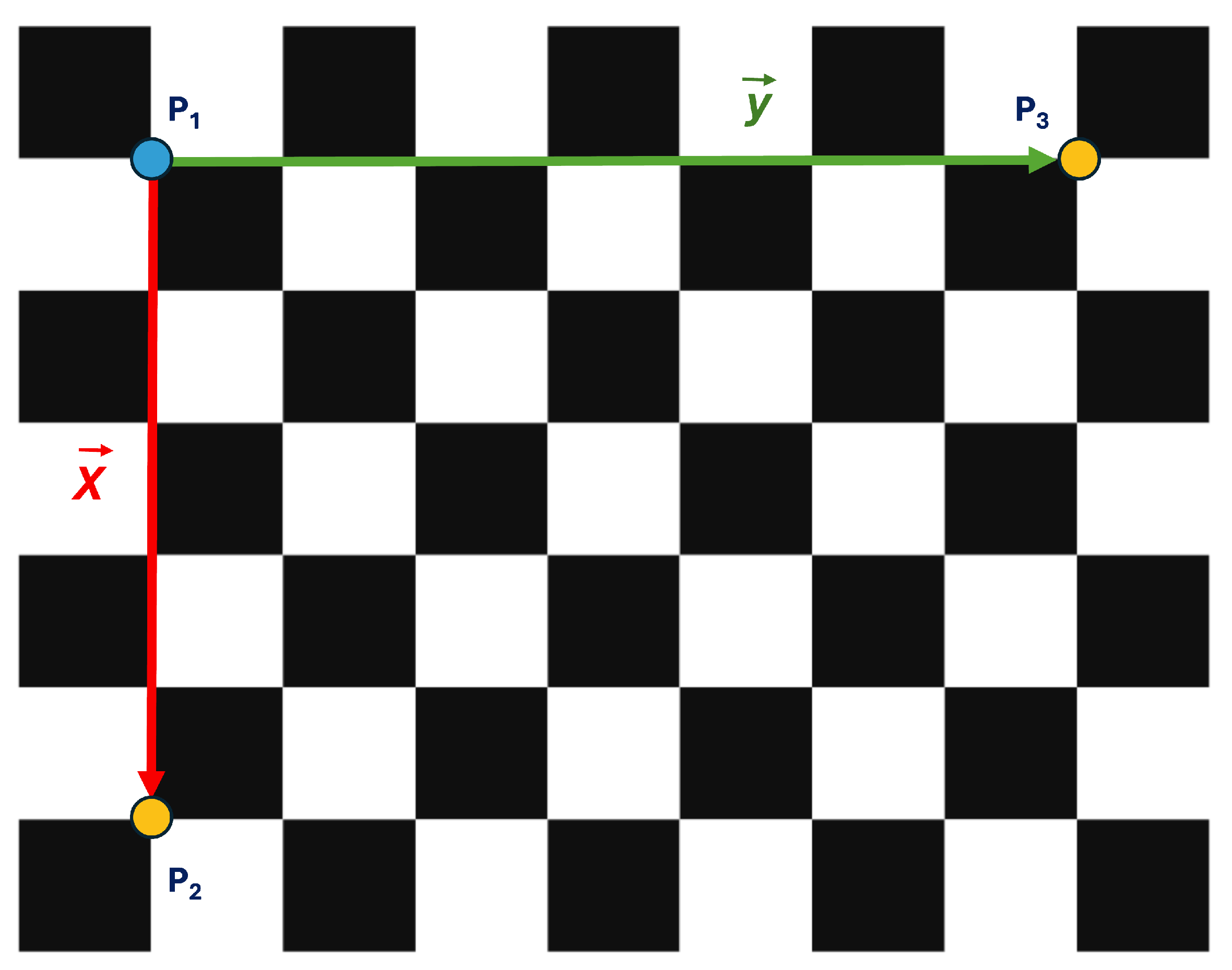
The world coordinate frame origin is located at point P 1 as shown in Figure 2. Following the right-hand rule convention for coordinate frames, the x and y from the origin point P 1 lie on the same plane, while the z axis is perpendicular upward from the plane. Therefore, the rotation matrix can be calculated as
R W C = x ^ y ^ z ^ ,
where x ^ R 3 , y ^ R 3 , and z ^ R 3 are the unit vectors in x, y, and z direction of the world coordinate frame { W } .
Consider that p 1 , p 2 , and p 3 are the position vectors of P 1 , P 2 , and P 3 expressed in the camera coordinate { C } . There is a possibility that the x and y vectors of the calibration board, as shown in Figure 2, may not be perpendicular due to a printing error. Therefore, we first compute the displacement vectors x and y between points P 1 - P 2 and P 1 - P 3 , respectively, as
x = p 2 p 1 and y = p 3 p 1 .
The unit vectors x ^ and y ^ can be calculated as
x ^ = x x and y ^ = y y .
Further, the unit vector z ^ is calculcated as
z ^ = x ^ × y ^ .
Finally, we compute the unit vector y ^ as
y ^ = z ^ × x ^ .
To develop the rotation matrix in Equation (4), the unit vectors x ^ , y ^ , and z ^ can be expressed as
x ^ = x i i ^ + x j j ^ + x k k ^ , y ^ = y i i ^ + y j j ^ + y k k ^ ,   and z ^ = z i i ^ + z j j ^ + z k k ^ .
Using Equations (4) and (9), we can construct the rotation matrix as
R W C = x i y i z i x j y j z j x k y k z k .
The translation vector from Equation (3) is expressed as
t W C = p 1 = p 1 x i ^ + p 1 y j ^ + p 1 z k ^ ,
since P 1 is origin of the world frame { W } , p 1 is expressed in the camera frame { C } . Finally, the world to camera transformation matrix can be constructed using Equations (3), (10) and (11) as
T W C = R W C t W C 0 1 = x i y i z i p 1 x x j y j z j p 1 y x k y k z k p 1 z 0 0 0 1 .
Therefore, T W C signifies that any point observed in the world coordinate system { W } , as shown in Figure 2, can be transformed to the camera coordinate system { C } .

2.4. World-to-Robot Transformation

In this research, the world-to-robot transformation matrix T W R was determined by measuring the positions and orientations of the robot base frame { R } and the world coordinate frame { W } . Figure 1 shows the robot arm model with robot base coordinate frame { R } , world coordinate frame { W } , camera coordinate frame { C } , and the pointer tool coordinate frame { P } . To measure the position of the world coordinate in the robot frame, a pointer tool mounted on the end-effector with known geometry can be positioned at the three points P 1 , P 2 , and P 3 , as shown in Figure 2. The coordinates of the three non-collinear points were measured manually by using the robot controller to position the pointer tip at each point. From the geometry of the robot, the pointer to the robot transformation can be calculated as
T P R = T J 1 R T P J n ,
where J = { J i i { 1 , , n } } is a set of robot reference frames on the n intermediate joints, and T J 1 R is the transformation from { J 1 } to { R } , and so on. The pointer to the robot base transformation matrix is expressed as
T P R = R P R t P R 0 1 R 4 × 4 ,
where R P R and t P R are the rotation matrix and translation vector of a transform from pointer { P } to robot base { R } .
To measure the relationship between robot base { R } and the world coordinate { W } , the translation vector t P R R 3 is measured at points P 1 , P 2 , and P 3 to generate q 1 , q 2 , and q 3 from the origin of { R } to these three points. Similar to Equation (5), the displacement vectors for the world to robot transformation are calculated as
x r = q 2 q 1 and y r = q 3 q 1 ,
where the suffix r is used to differentiate Equation (15) from world to camera transformation Equation (5). Further, calculating the unit vectors as
x ^ r = x r x r and y ^ r = y r y r .
Then, using Equation (16) to calculate the unit vector along z-axis as
z ^ r = x ^ r × y ^ r .
Finally, calculating y ^ r as
y ^ r = z ^ r × x ^ r .
To find the transformation matrix from world to robot, the rotation matrix R W R R 3 × 3 and translation vector t W R can be developed similarly to Equations (10) and (11) as
R W R = x r i y r i z r i x r j y r j z r j x r k y r k z r k and     t W R = q 1 = q 1 x i ^ + q 1 y j ^ + q 1 z k ^ .
Using the values of the rotation matrix and translation vector from Equation (19), the transformation matrix from world to robot is developed as
T W R = R W R t W R 0 1 = x r i y r i z r i q 1 x x r j y r j z r j q 1 y x r k y r k z r k q 1 z 0 0 0 1 .

2.5. Camera-to-Robot Transformation

The ultimate goal of performing the robot hand-to-eye calibration is to find the position of the point observed in the camera frame in the robot frame. This is to find the transformation matrix T C R between the camera frame { C } to the robot frame { R } . From Figure 1, the transformation matrices can be expressed using transformation composition as
T W R = T C R · T W C .
Since T C R is the unknown, post-multiplying by the inverse of T W C on both sides of Equation (21), we get the following equation:
T C R = T W R · T W C 1 .
By obtaining T C R , the robot hand-to-eye calibration process is complete.

2.6. Stereo Reprojection

Consider a point P with its image location u = ( u , v ) in the left stereo image plane and its corresponding disparity value D [ u , v ] = d , where D R i × j is a disparity map formed using the stereo images of size ( i , j ) . Constructing a vector v = u v d 1 T R 4 and using Equation (2), we get
x ˜ = Q · v ,
where x ˜ = x ˜ y ˜ z ˜ w ˜ T and x c = x ˜ / w ˜ = x c y c z c 1 T R 4 are the coordinates of point P in the camera frame. The same point P in the robot frame { R } can be calculated as
x r = T C R · x c ,
where x r = x r y r z r 1 T R 4 are the coordinates of the given point in the robot coordinate frame. Therefore, from Equations (23) and (24), we can transform any point from the stereo image plane to the robot coordinate frame.

3. Evaluation

In this section, we present the experimental setup, which includes a UR10e robot from Universal Robots A/S (DK-5260 Odense S, Denmark), a ZED2i stereo camera from StereoLabs (San Francisco, CA, USA), a calibration board, and a computer with required software tools to perform the calibration and evaluation. Further, we present the evaluation method in Section 3.3, which leads to Contribution 4 in Section 1.3.

3.1. Experimental Setup

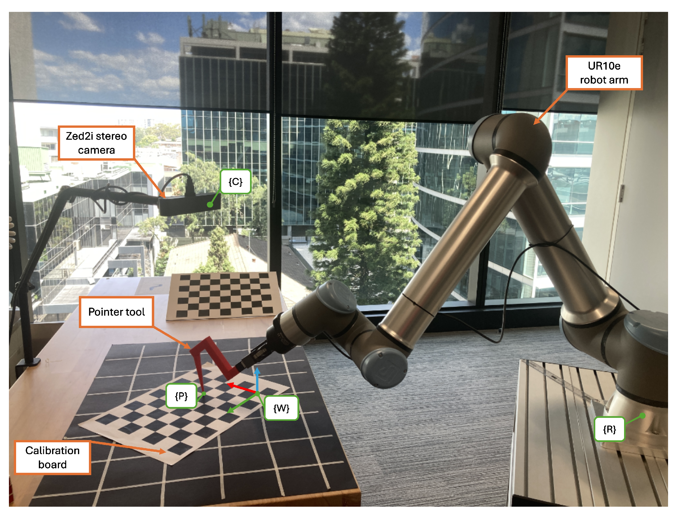
The experimental setup, as shown in Figure 3, consists of a UR10e robot with a pointer tool at the end-effector, a calibration board, and a Zed2i stereo camera. Figure 3 also shows the positions of different frames in correspondence to the experimental model shown in Figure 1.

3.1.1. Stereo Camera

The Zed2i stereo camera is used for depth detection. The camera was mounted on the stand and faces downward towards the workbench as shown in Figure 3. The camera frame { C } was positioned on the left camera lens of the stereo setup inside the stereo casing. The available resolutions of Zed2i camera are as follows: ( 672 × 376 ) , ( 1280 × 720 ) , ( 1920 × 1080 ) , and ( 2208 × 1242 ) . In this research, we used a ( 672 × 376 ) resolution for stereo calibration and maintained this resolution throughout. The depth accuracy of Zed2i camera was less than 1 % up to 3 m [32].

3.1.2. Calibration Board

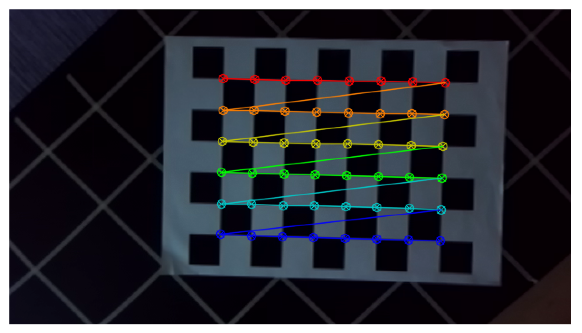
The calibration board is a 9 × 7 chessboard of squares measuring 39 mm, with 8 × 6 inner grid points used for calibration. Figure 4 shows a rendering of the 8 × 6 inner grid points on the chessboard. The first point in Figure 4 in the top left corner is the chessboard world origin point corresponding to point P 1 in Figure 2. The world coordinate frame { W } is located at point P 1 . Figure 3 also shows the position of { W } with the coordinate axes x ^ , y ^ , and z ^ represented as red, green, and blue, respectively.

3.1.3. Robot Arm

The robot arm used in this research is a UR10e robot arm from Universal Robots as shown in Figure 3. The robot is connected with the Robotiq gripper 2f 85. The gripper holds a custom-made 3D-printed pointer tool. The pointer to robot transformation T P R shown in Equation (13) is developed by considering the base reference frame of the Robotiq gripper and the pointer reference frame at the tip of the pointer as shown in Figure 3.
The robot transformation up to the robot flange for the UR10e robot [33] can be achieved using Denavit–Hartenberg [34] parameters, as shown in Table 1.

3.1.4. Pointer Tool

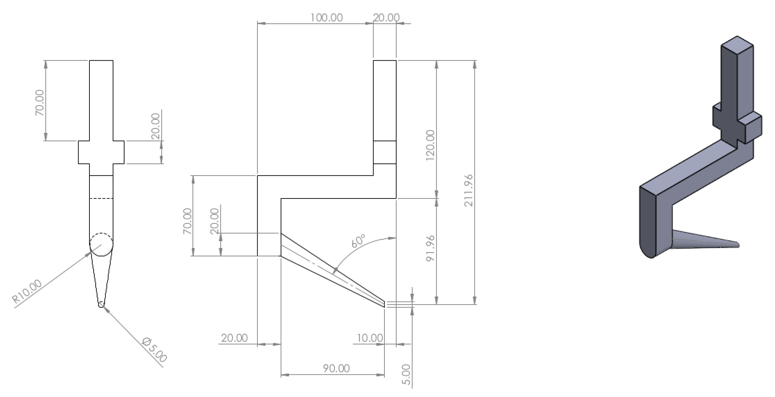
The specifications of the pointer tool are shown in Figure 5, developed using SolidWorks 2025 CAD (Computer-Aided Design) software. The tool is manufactured using a Raise3D Pro3 Plus HS 3D printer from Raise 3D (Costa Mesa, CA, USA). The material used was PLA (Polylactic Acid) with 15 % in-fill.

3.2. Computer and Software

The UR10e robot is operated using a teach pendant controller. A computer with a 12th Gen Intel N97 (@3.60 GHz), 12 GB RAM, 512 GB SSD, and Kubuntu 22.04 operating system was used to run image processing tasks and to operate the robot externally.
The code for the image processing task was developed in Python 3.10.12 using the OpenCV library [35]. ROS2 Humble (Robot Operating System) [36] was used for external robot control. A URDF (Unified Robot Description Format) file for the robot has been developed, including the Robotiq gripper and the pointer tool. The Tf2 transform library in ROS2 is used to compute the transformation T P R as mentioned in Equation (13).

3.3. Evaluation Metric

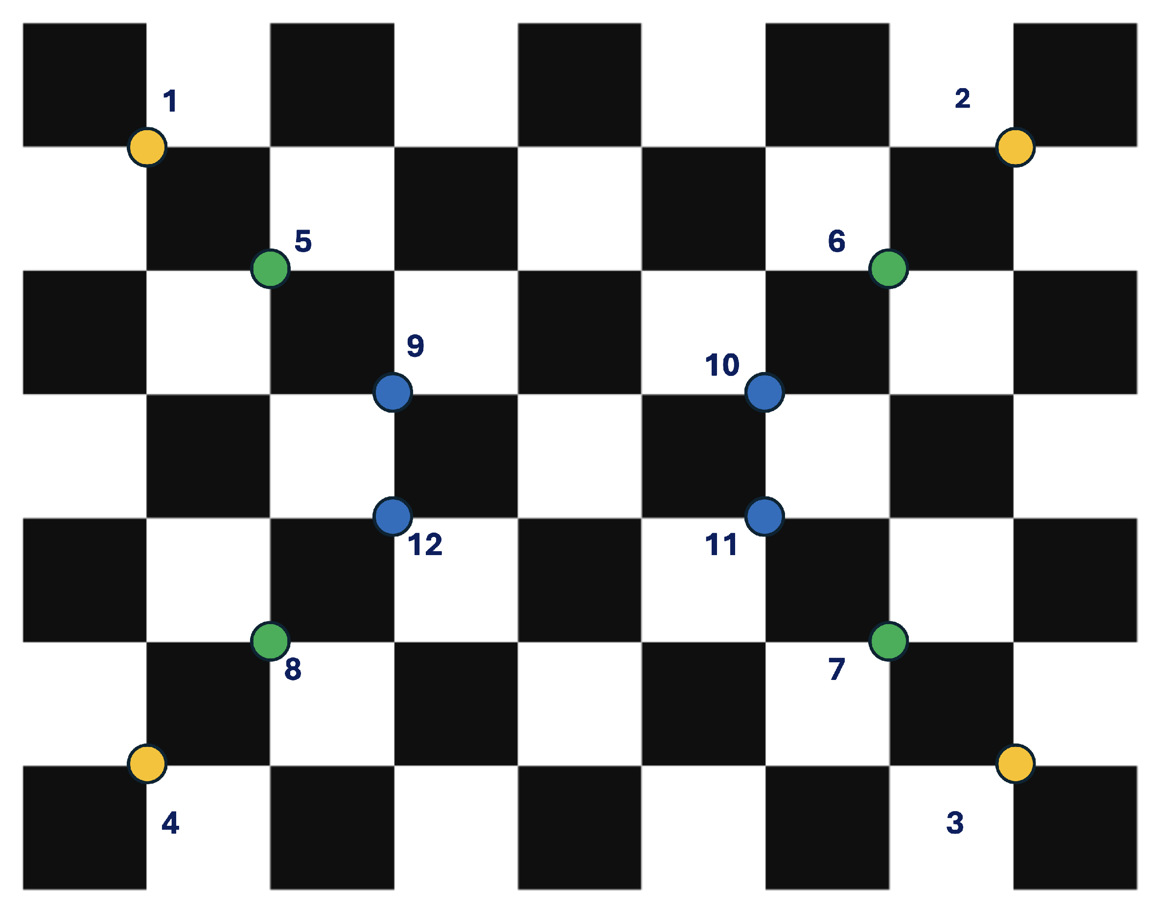
To evaluate the camera-to-robot point transformation, we select 12 points on the chessboard following a rectangular pattern, as shown in Figure 6. The purpose of selecting these points is to cover a wide area of the calibration board. The evaluation process will compare the calculated robot coordinates obtained from the camera-to-robot transformation matrix T C R with the actual robot coordinates obtained using the pointing tool. The RMSE (Root Mean Square Error) will be calculated as
RMSE = 1 N i = 1 N ( c i a i ) 2 ,
where c is the calculated, and a is the actual robot position for the N = 12 points. Error will be calculated for each set of coordinates ( x ^ r , y ^ r , z ^ r ) in the robot frame { R } .
For calculated coordinate values, the chessboard corner points are first detected, as shown in Figure 4. Then, isolating the image plane coordinates ( u , v ) of the 12 points of interest from Figure 6. These points from the image plane, along with their disparity values D [ u , v ] = d , can be reprojected into the camera frame by using Equation (23). Then, using Equation (24), the points will be transformed into the robot coordinates.

4. Results

In this section, we present the results obtained by using the methods developed and testing it on the experimental setup from Section 3.1. The transformation results from the image plane to the robot coordinate frame are evaluated. A repeatability analysis is performed on the evaluation metric presented in Section 3.3 along with the ground truth. Furthermore, a qualitative analysis is performed to evaluate the robot path planning given the transformations of the image points into the robot coordinate space.

4.1. One-Off Stereo Calibration Results

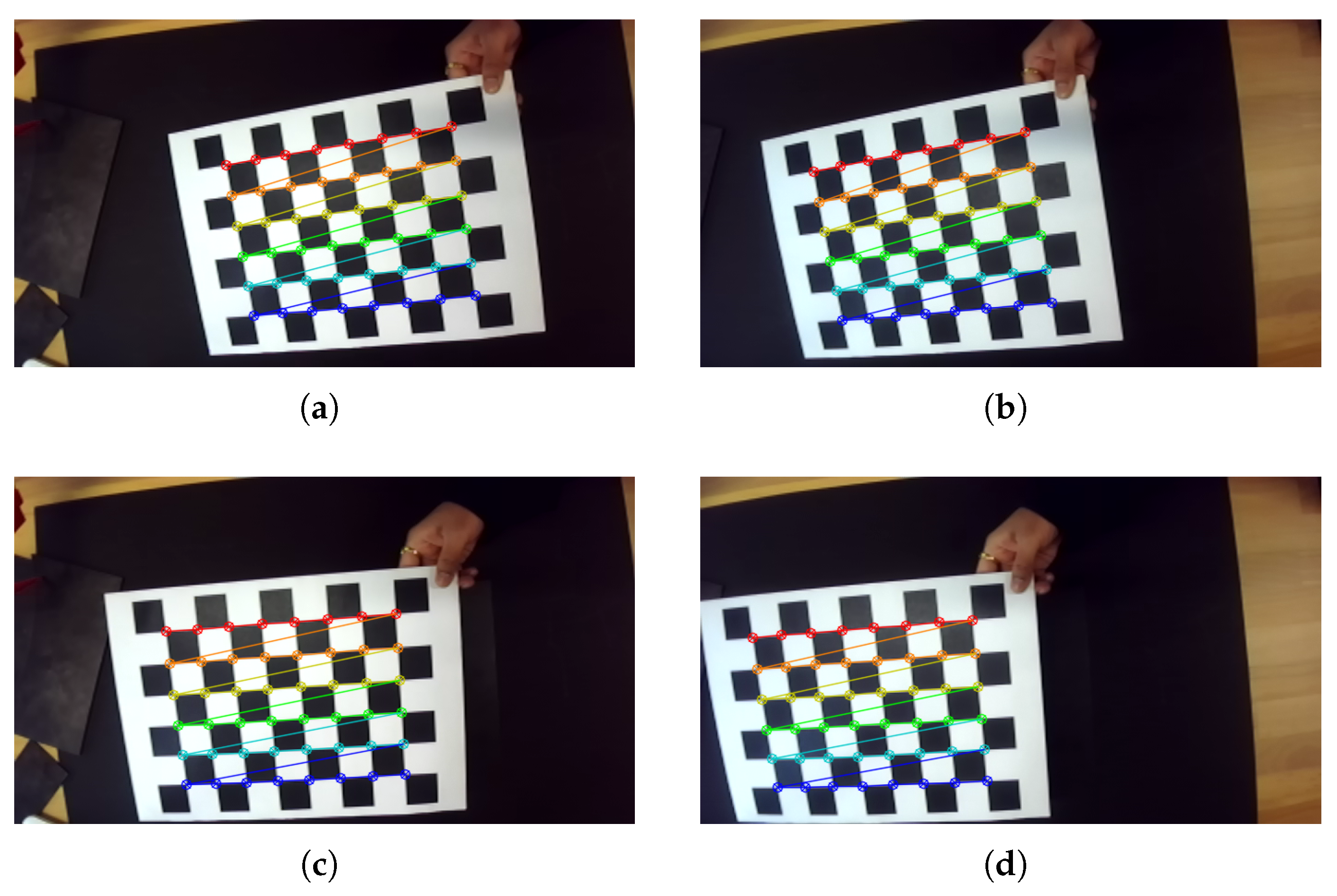
The one-off stereo calibration process involved live rendering of the chessboard pattern. The live rendering process was done to ensure that all the areas of the image plane were covered. It is beneficial to ensure the calibration pattern is visible within the field of view of both cameras of the stereo setup. Also, it is important to avoid motion-blurred images to ensure the detection of image points on the calibration board.
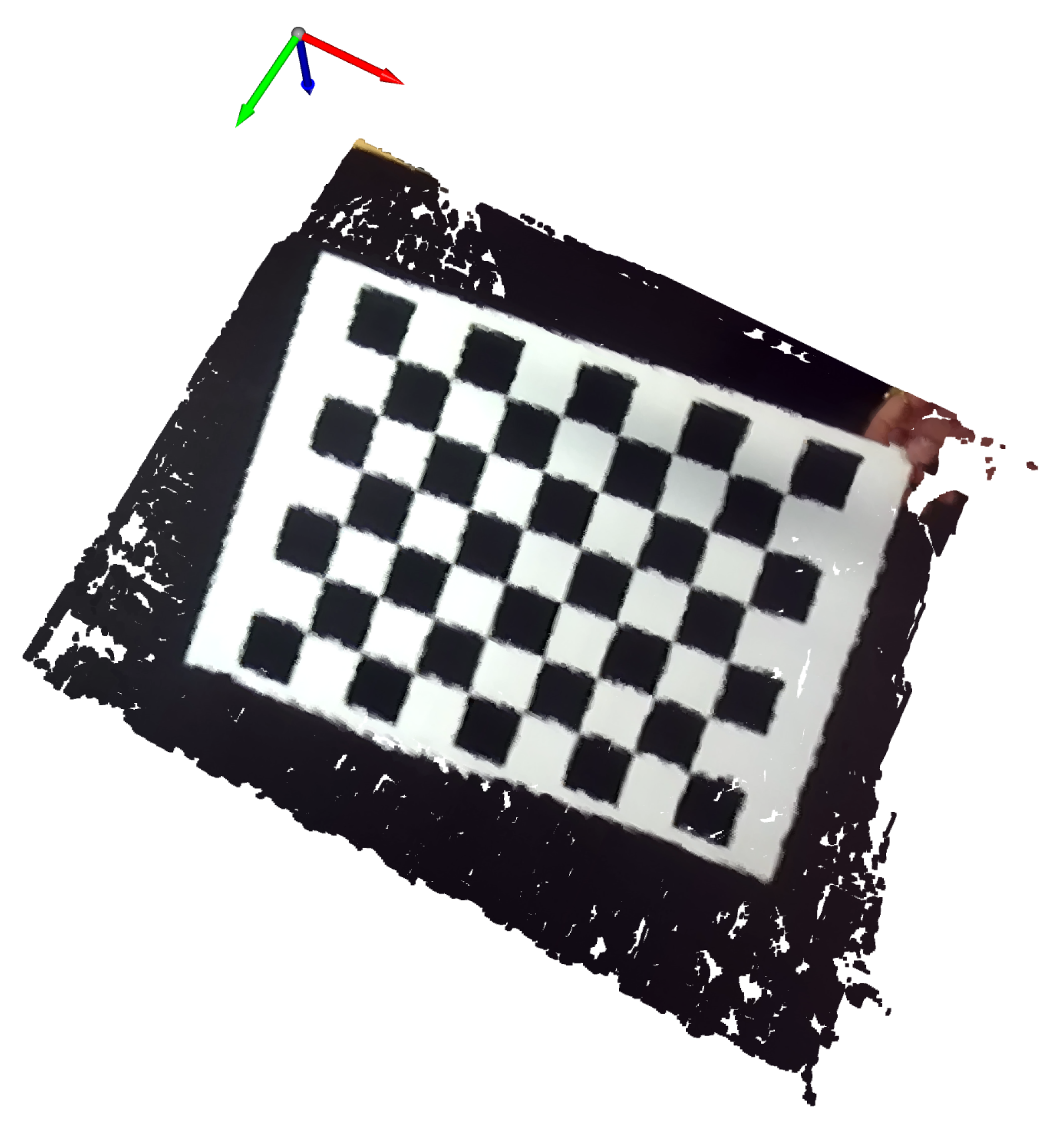
Figure 7 shows the live rendering during the data collection stage of the stereo calibration process. We collected 20 images for stereo calibration. For stereo matching, the minimum disparity was 0. The minimum disparity ensures the furthest distance we expect to detect. The disparity factor was 12, a multiple of 16, and the block size for image matching along the rectified stereo image was 5. With these parameters, we achieved a reprojection error of 0.26 pixels. There were no further improvements in the reprojection errors beyond 20 images, and any error below 1 pixel is considered acceptable for reprojection. For visual evaluation, we also generate a point cloud of the first image from the collection of camera calibration images, as shown in Figure 8.
The stereo calibration process must be performed only once. The camera intrinsic and extrinsic parameters will remain constant once the stereo calibration is completed. This means the camera does not need to be mounted on the stand during stereo calibration. Also, if the camera position is changed after hand-to-eye calibration, there is no need to perform stereo camera calibration again. Therefore, with this approach, once the stereo camera calibration is done with a reprojection error of less than 1 pixel, it can be used in robot hand-to-eye calibration.

4.2. Image-to-Camera-to-Robot Transformation Results

The results of the 12 points of interest, presented in Section 3.3, from the image plane to the camera coordinates and from the camera coordinates to the robot coordinates are shown in Table 2 where ( u , v ) are the pixel coordinates of the 12 points in the left image frame, d is the corresponding disparity value, ( x c , y c , z c ) are the camera coordinates, and ( x r , y r , z r ) are the robot coordinates of these points, calculated using Equation (24).

4.3. Robot Hand-to-Eye Quantitative Error Analysis

The actual positions in Table 3 are ( x a c t , y a c t , z a c t ) . The actual position is measured by moving the tip of the pointer tool to the 12 points on the chessboard shown in Figure 6 and obtaining the position reading from the robot controller. Upon calculating RMSE for each set of coordinates using Equation (25) and the values from Table 3, the RMSE along x, y, and z directions are x RMSE = 0.926 mm, y RMSE = 0.859 mm, and z RMSE = 1.305 mm, respectively.

4.4. Repeatability Analysis

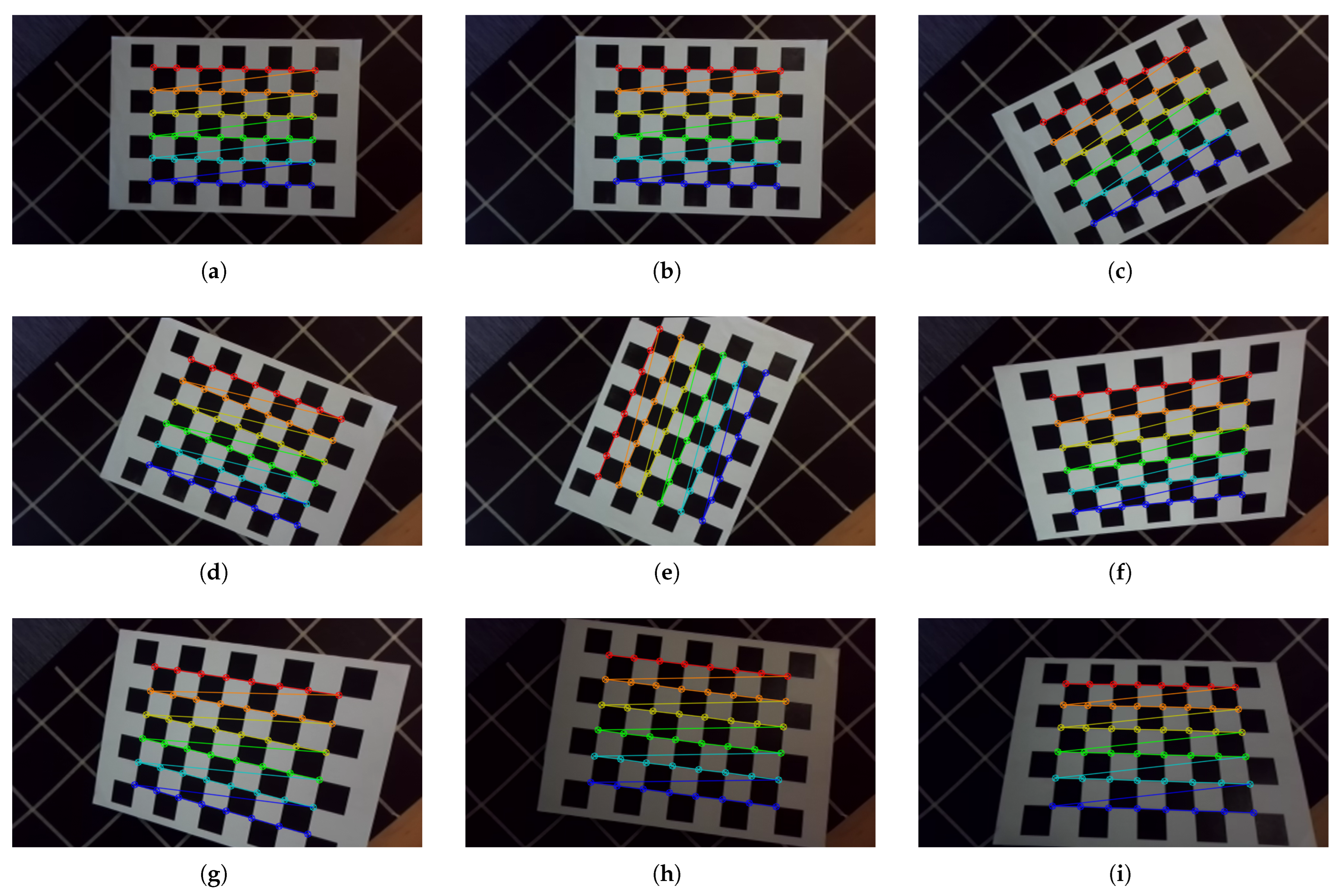
We repeat the experiments to perform a repeatability analysis by evaluating the 12 evaluation points and computing the RMSE for each direction. A total of ten experiments were performed, including the one shown in Table 3. Figure 9 shows the different positions and orientations of the chessboard for the additional nine experiments (Experiments 2 to 10). Figure 9a–e show the calibration board placed flat on the workbench. Figure 9f–i show the calibration board placed inclined to the workbench. This group of experiments were designed to vary the object’s depth relative to the camera. Figure 9h,i show the experimental conditions in a lower illumination setting. The two test cases (Experiments 9 and 10) were selected to evaluate depth estimation under lower illumination. Each of these experimental cases was selected to address the position and orientation of the stereo camera within the field of view, as well as the varying depth range achieved by varying the inclination. The RMSE values for the ten experiments are presented in Table 4.
Upon calculating the RMSE for the ten experiments for the 12 evaluation points shown in Table 4, the median values are x ˜ RMSE = 0.8469 mm, y ˜ RMSE = 0.6713 mm, and z ˜ RMSE = 1.7402 mm.
Figure 10 shows the distribution of RMSE values of the ten experiments. From the plot, the interquartile range (IQR) for RMSE values in x and y directions is between 0.5 and 1 mm. The IQR of the RMSE values in the z-direction is between 1.5 and 2.5 mm, with outliers from Experiments 9 and 10. The outliers are associated with the evaluation setup of the calibration board in Figure 9h,i. These outliers are due to changes in the environmental illumination. However, these outliers remain within the depth accuracy of the ZED2i stereo camera, which is approximately 1 % within 3 m [32]. Therefore, for a depth of approximately 500 mm in each experimental case, an error of 5 mm is acceptable according to the camera specifications.

4.5. Qualitative Evaluation of Robot Position on the Evaluation Metric

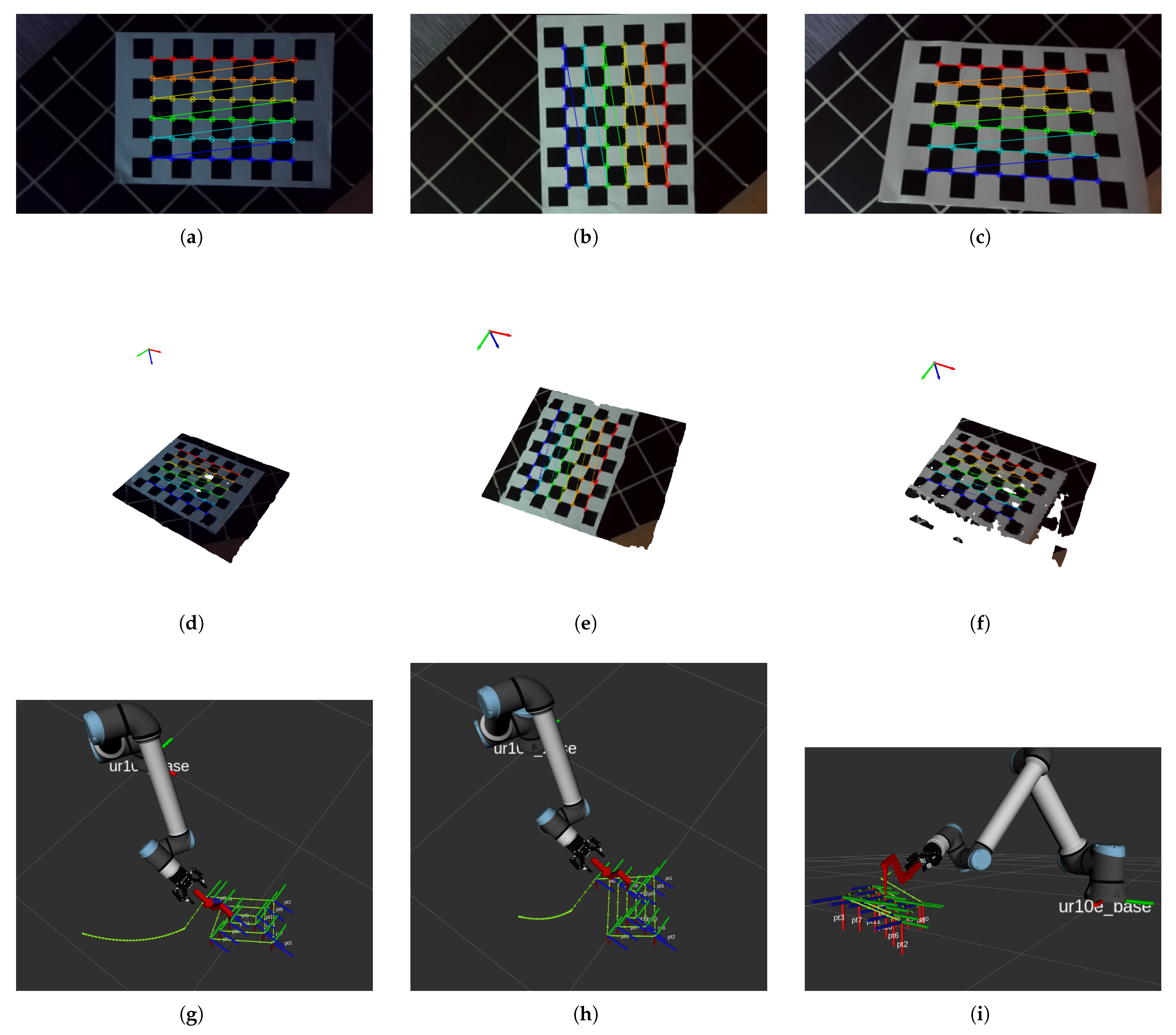
A qualitative evaluation is performed of the 12 evaluation points for the 10 experiments shown in Figure 6. The qualitative evaluation involves three cases as per the three positions of the chessboard relative to the stereo camera in Figure 11: (a, d, g) horizontal, (b, e, h) vertical, and (c, f, i) inclined.
Figure 11a–c show the detection of the calibration pattern in the left image of the stereo camera. The stereo images are projected in the camera frame using Equation (23). The visualisation is performed using the Open3D Python package [37]. Figure 11d–f show the point cloud visualisation of the chessboard along with the camera coordinate frame. Each point in the point cloud can be further transformed to the robot coordinate using Equation (24).
The 12 evaluation points obtained by transforming from the camera to the robot coordinate system are used as via points for robot path-following during visual evaluation. The path following is performed using a ROS2 [36] library called MoveIt2 [38]. The visualisation was performed in the ROS2 3D visualiser, RViz. After successful planning and visualisation of the path in RViz, a MoveIt2 programme was developed to execute it. Figure 11g–i show the pattern formed by sequentially visiting the 12 evaluation points as shown in Figure 6.
The qualitative evaluation allows the visual inspection of the accuracy of the hand-to-eye calibration. The evaluation shows that the robot can traverse in its workspace to points observed in the camera. The tilted board in Figure 11i shows that the robot can access points that are in an inclined plane to the workbench. This also shows that the robot can access varying depths at different points. Figure 11 works as a visual representation of observing the points in the image frame then reprojecting them in the camera coordinate frame and ultimately in the robot coordinate frame. Furthermore, an automated practical workflow is implemented to detect points of interest in the stereo images that the robot end-effector eventually reaches.

5. Discussion

In this section, we discuss the method developed in this research along with its evaluation process. We further compare the approach with other studies on hand–eye calibration.

5.1. Collecting Data Only Once

In this research, we developed a method to establish the relationship between a camera and a robot by measuring world coordinates using a pointer tool held by the robot’s gripper. This procedure was performed only once: first identifying the three non-collinear points in the world coordinate frame, as shown in Figure 2, and then measuring the same set of points using the robot pointer tool. The method presented in [28] used 15 robot positions and captured the images in each position. Compared with the method developed in this research, the robot is moved to three non-collinear points, and a single stereo image is used for hand-to-eye calibration.
The advantage of the approach introduced in this research is that it requires no multiple images of the calibration board or multiple robot positions to solve for the camera-to-robot transformation matrix using iterative methods. If the robot or camera is moved, a single stereo image of a board with three non-collinear points is sufficient to determine the world-to-camera transformation matrix. Furthermore, moving the robot to three non-collinear points P 1 , P 2 , and P 3 in Figure 2 is sufficient to find the world-to-robot transformation matrix.

5.2. Robot Hand-to-Eye Error Analysis

The root mean square error was less than 1 mm in x and y direction and less than 2 mm in the z direction of the robot coordinate frame. The results presented in [28] show that the error in x and y direction was within 1 mm and in z direction was ± 3.5 mm. Upon calculating the median of RMSE values from Table 4, the errors are lower compared to [28]. This type of error is acceptable for most applications that allow a certain tolerance for safe operation. The results presented in [18,26] are more focused on the rotation and translation error of the transformation matrix. Since the method in this research is more focused on the positional accuracy in the robot space, a comparison is made with [28], which uses a similar evaluation method of selecting random points on the chessboard and calculating error between the calculated values for the transformation matrix and the manual measurement from the robot controller.
The hand-to-eye error is subject to the accuracy of depth estimation of the stereo camera. The experiments are performed for the Zed2i stereo camera. The depth accuracy of the camera is less than 1 % up to 3 m depth [32]. Given that the maximum depth of the setup in the experiments is approximately 500 mm, according to the camera specification, the expected depth accuracy is 5 mm. In all the experiments, the RMSE for the z direction has been within 5 mm. The higher RMSE in the z direction is attributed to the depth accuracy of the stereo camera. Thus, the camera’s accuracy also plays a vital role in the robot hand-to-eye calibration process presented in this research.

5.3. Computational Efficiency

The method presented in this research does not use an iterative method to compute the optimal parameters of the transformation matrix. The computation process is sequential, where mathematical operations are performed one after the other. The computational efficiency depends on the types of CPUs used. The three non-collinear points could be measured by moving the robot to these three points and obtaining their coordinates. In our experiments, the calibration time is primarily due to manual measurement of the three points, which takes less than five minutes on a UR10e robot. The remaining computation time is negligible.

5.4. Generalisation over Other Camera Systems and Robots

The method developed in this research uses a stereo camera, where the one-off stereo calibration was performed using pre-existing methods [24,30]. Since depth information and point reprojection from the image plane to the camera frame are the first steps in the robot hand-to-eye calibration process, any 3D camera that allows reprojection of image points to camera coordinates will also work. This process may also yield similar results with active stereo-vision cameras that are factory-calibrated for depth estimation. RGB-D cameras with depth information can also be used after RGB-D camera calibration. Therefore, as long as the depth can be estimated from the camera, the robot hand-to-eye calibration method introduced in this research is applicable.
The robot arm used in this research is UR10e. The relationship between the camera frame and the robot base is established for the hand-to-eye transformation. In this research, the design of the 3D-printed pointer tool was inspired by the layout of a welding torch. However, other pointing devices can be used to perform the hand-to-eye calibration methods introduced in this research. Therefore, in principle, a robot arm with reach within the depth-based camera’s field of view can be calibrated using the hand-to-eye calibration method presented in this research.

5.5. Future Scope

The method developed in this research was particularly developed for robot hand-to-eye calibration. The calibration pattern plays a vital role in establishing a standard world-origin coordinate system for the world-to-camera and world-to-robot mappings. While the calibration pattern helps in measuring the displacement vectors, in reality, only three non-collinear points are required for developing the transformation matrix. Therefore, further work on robot hand-to-eye calibration can be done by considering different calibration patterns, such as ChArUCo boards [39].
Future work can also be extended to dynamic scenarios in which the positions of the camera and robot change. Furthermore, the applicability can be tested on robot arms and on a camera mounted on a mobile robot, provided that the relative position between the camera and the robot remains unchanged. Further investigation can be conducted under varying environmental conditions, such as outdoor settings, where different illumination settings need to be considered.

6. Conclusions

In this research, we developed a novel robot hand-to-eye calibration method using only three non-collinear points from a single stereo image. We performed stereo calibration with live rendering to select the best images that exhibit a clearly visible pattern within the field of view of both cameras in the stereo setup. We achieved a calibration error of 0.26 pixels, which is sufficient for detailed point clouds and depth estimation. Using depth information from a stereo camera and a single stereo image pair, we developed a mapping between the image plane in two dimensions and the robot’s coordinates in three dimensions. We evaluated our method by experimenting with a robot arm and a stereo camera. We achieved a median RMSE less than 1 mm in x and y directions and less than 2 mm in z direction.

Author Contributions

Conceptualization, P.K. and G.F.; methodology, P.K., G.F.; software, P.K.; validation, P.K., G.F., F.A., J.J.Z., P.H., formal analysis, P.K., G.F.; investigation, P.K.; data curation, P.K.; writing—original draft preparation, P.K.; writing—review and editing, P.K., G.F., F.A., J.J.Z., P.H.; visualization, P.K.; supervision, G.F., F.A., J.J.Z., P.H. All authors have read and agreed to the published version of the manuscript.

Funding

This research received no external funding.

Institutional Review Board Statement

Not applicable.

Informed Consent Statement

Not applicable.

Data Availability Statement

No new data were created or analysed in this study. Data sharing is not applicable to this article.

Conflicts of Interest

The authors declare no conflicts of interest.

Abbreviations

The following abbreviations are used in this manuscript:
CobotCollaborative Robot
CADComputer-Aided Design
DoFDegree of Freedom
IQRInterquartile Range
LIDARLight Detection and Ranging
PLAPolylactic Acid
RGBRed Green Blue
RGB-DRed, Green, Blue, Depth
RMSERoot Mean Square Error
ROSRobot Operating System
SGBMSemi-Global Block Matching
SONARSound Navigation and Ranging
URDFUnified Robot Description Format

References

  1. Kadam, P.; Fang, G.; Zou, J.J. Object Tracking Using Computer Vision: A Review. Computers 2024, 13, 136. [Google Scholar] [CrossRef] [Scilit]
  2. Kadam, P.; Fang, G.; Amirabdollahian, F.; Zou, J.J.; Holthaus, P. Hand Pose Detection Using YOLOv8-pose. In 2024 IEEE Conference on Engineering Informatics, ICEI 2024; IEEE: Melbourne, Australia, 2024. [Google Scholar] [CrossRef] [Scilit]
  3. Pachtrachai, K.; Vasconcelos, F.; Chadebecq, F.; Allan, M.; Hailes, S.M.; Pawar, V.M.; Stoyanov, D.V. Adjoint Transformation Algorithm for Hand–Eye Calibration with Applications in Robotic Assisted Surgery. Ann. Biomed. Eng. 2018, 46, 1606–1620. [Google Scholar] [CrossRef] [Scilit]
  4. Xu, Y.; Mao, Y.; Tong, X.; Tan, H.; Griffin, W.; Kannan, B.; DeRose, L. Robotic Handling of Surgical Instruments in a Cluttered Tray. IEEE Trans. Autom. Sci. Eng. 2015, 12, 775–780. [Google Scholar] [CrossRef] [Scilit]
  5. Kaipa, K.; Kankanhalli-Nagendra, A.; Kumbla, N.; Shriyam, S.; Thevendria-Karthic, S.; Marvel, J.; Gupta, S. Addressing perception uncertainty induced failure modes in robotic bin-picking. Robot. Comput.-Integr. Manuf. 2016, 42, 17–38. [Google Scholar] [CrossRef] [Scilit]
  6. Zhuang, C.; Li, S.; Ding, H. Instance segmentation based 6D pose estimation of industrial objects using point clouds for robotic bin-picking. Robot. Comput.-Integr. Manuf. 2023, 82, 102541. [Google Scholar] [CrossRef] [Scilit]
  7. Zhuang, C.; Wang, Z.; Zhao, H.; Ding, H. Semantic part segmentation method based 3D object pose estimation with RGB-D images for bin-picking. Robot. Comput.-Integr. Manuf. 2021, 68, 102086. [Google Scholar] [CrossRef] [Scilit]
  8. Sun, H.; Zhang, Z.; Wang, H.; Wang, Y.; Cao, Q. A Novel Robotic Grasp Detection Framework Using Low-Cost RGB-D Camera for Industrial Bin Picking. IEEE Trans. Instrum. Meas. 2024, 73, 2513212. [Google Scholar] [CrossRef] [Scilit]
  9. Le, T.T.; Lin, C.Y. Bin-picking for planar objects based on a deep learning network: A case study of usb packs. Sensors 2019, 19, 3602. [Google Scholar] [CrossRef] [Scilit] [PubMed]
  10. Torres, P.; Arents, J.; Marques, H.; Marques, P. Bin-Picking Solution for Randomly Placed Automotive Connectors Based on Machine Learning Techniques. Electronics 2022, 11, 476. [Google Scholar] [CrossRef] [Scilit]
  11. Micallef, K.; Fang, G.; Dinham, M. Automatic Seam Detection and Path Planning in Robotic Welding. In Robotic Welding, Intelligence and Automation; Lecture Notes in Electrical Engineering; Springer: Berlin/Heidelberg, Germany, 2011; Volume 88, pp. 23–32. [Google Scholar] [CrossRef] [Scilit]
  12. Shah, H.N.M.; Sulaiman, M.; Shukor, A.Z. Autonomous detection and identification of weld seam path shape position. Int. J. Adv. Manuf. Technol. 2017, 92, 3739–3747. [Google Scholar] [CrossRef] [Scilit]
  13. Schleth, G.; Kuss, A.; Kraus, W. Workpiece localization methods for robotic welding—A review. In Proceedings of the 50th International Symposium on Robotics, ISR 2018, Munich, Germany, 20–21 June 2018; pp. 50–55. [Google Scholar]
  14. D’Avella, S.; Tripicchio, P.; Avizzano, C. A study on picking objects in cluttered environments: Exploiting depth features for a custom low-cost universal jamming gripper. Robot. Comput.-Integr. Manuf. 2020, 63, 101888. [Google Scholar] [CrossRef] [Scilit]
  15. Li, X.; Cao, R.; Feng, Y.; Chen, K.; Yang, B.; Fu, C.W.; Li, Y.; Dou, Q.; Liu, Y.H.; Heng, P.A. A Sim-to-Real Object Recognition and Localization Framework for Industrial Robotic Bin Picking. IEEE Robot. Autom. Lett. 2022, 7, 3961–3968. [Google Scholar] [CrossRef] [Scilit]
  16. Dhanda, M.; Rogers, B.A.; Hall, S.; Dekoninck, E.; Dhokia, V. Reviewing human-robot collaboration in manufacturing: Opportunities and challenges in the context of industry 5.0. Robot. Comput.-Integr. Manuf. 2025, 93, 102937. [Google Scholar] [CrossRef] [Scilit]
  17. Shah, R.; Doss, A.S.A.; Lakshmaiya, N. Advancements in AI-enhanced collaborative robotics: Towards safer, smarter, and human-centric industrial automation. Results Eng. 2025, 27, 105704. [Google Scholar] [CrossRef] [Scilit]
  18. Daniilidis, K. Hand-Eye Calibration Using Dual Quaternions. Int. J. Robot. Res. 1999, 18, 286–298. [Google Scholar] [CrossRef] [Scilit]
  19. Yang, J.; Li, D.; Waslander, S. Probabilistic Multi-View Fusion of Active Stereo Depth Maps for Robotic Bin-Picking. IEEE Robot. Autom. Lett. 2021, 6, 4472–4479. [Google Scholar] [CrossRef] [Scilit]
  20. Dinham, M.; Fang, G. Autonomous weld seam identification and localisation using eye-in-hand stereo vision for robotic arc welding. Robot. Comput.-Integr. Manuf. 2013, 29, 288–301. [Google Scholar] [CrossRef] [Scilit]
  21. Song, K.T.; Wu, C.H.; Jiang, S.Y. CAD-based Pose Estimation Design for Random Bin Picking using a RGB-D Camera. J. Intell. Robot. Syst. Theory Appl. 2017, 87, 455–470. [Google Scholar] [CrossRef] [Scilit]
  22. Zhang, Z. Microsoft Kinect Sensor and Its Effect. IEEE MultiMedia 2012, 19, 4–10. [Google Scholar] [CrossRef] [Scilit]
  23. Kaehler, A.; Bradski, G. Learning OpenCV 3: Computer Vision in C++ with the OpenCV Library, 1st ed.; O’Reilly Media: Beijing, China, 2017. [Google Scholar]
  24. Zhang, Z. A Flexible New Technique for Camera Calibration. In IEEE Transactions Pattern Analysis Machine Intelligence; IEEE: Piscataway, NJ, USA, 2000; Volume 22. [Google Scholar] [CrossRef] [Scilit]
  25. Horn, B. Robot Vision, mit press edition ed.; The MIT electrical engineering and computer science series; MIT Press: Cambridge, MA, USA, 1986. [Google Scholar]
  26. Tsai, R.; Lenz, R. A new technique for fully autonomous and efficient 3D robotics hand/eye calibration. IEEE Trans. Robot. Autom. 1989, 5, 345–358. [Google Scholar] [CrossRef] [Scilit]
  27. Xu, D.; Wang, C.; Yixuan, T.; Dong, X.; Huo, L.; Li, Y.; Zhang, Q.; Feng, X. A fast and straightforward hand-eye calibration method using stereo camera. In Proceedings of the 2022 7th International Conference on Automation, Control and Robotics Engineering (CACRE), Xi’an, China, 14–16 July 2022. [Google Scholar] [CrossRef] [Scilit]
  28. Dinham, M.; Fang, G. A low cost hand-eye calibration method for arc welding robots. In Proceedings of the 2009 IEEE International Conference on Robotics and Biomimetics, ROBIO 2009, Guilin, China, 19–23 December 2009; pp. 1889–1893. [Google Scholar] [CrossRef] [Scilit]
  29. Shiu, Y.C.; Ahmad, S. Calibration of Wrist-Mounted Robotic Sensors by Solving Homogeneous Transform Equations of the Form AX = XB. IEEE Trans. Robot. Autom. 1989, 5, 16–29. [Google Scholar] [CrossRef] [Scilit]
  30. Bouguet, J.Y. Camera Calibration Toolbox for Matlab; CaltechDATA: Pasadena, CA, USA, 2022. [Google Scholar] [CrossRef]
  31. Hirschmüller, H. Stereo processing by semiglobal matching and mutual information. IEEE Trans. Pattern Anal. Mach. Intell. 2008, 30, 328–341. [Google Scholar] [CrossRef] [Scilit] [PubMed]
  32. Abdelsalam, A.; Mansour, M.; Porras, J.; Happonen, A. Depth accuracy analysis of the ZED 2i Stereo Camera in an indoor Environment. Robot. Auton. Syst. 2024, 179, 104753. [Google Scholar] [CrossRef] [Scilit]
  33. Universal Robots. DH Parameters for Calculations of Kinematics and Dynamics. Available online: https://www.universal-robots.com/articles/ur/application-installation/dh-parameters-for-calculations-of-kinematics-and-dynamics/ (accessed on 16 November 2025).
  34. Denavit, J.; Hartenberg, R.S. A Kinematic Notation for Lower-Pair Mechanisms Based on Matrices. J. Appl. Mech. 1955, 22, 215–221. [Google Scholar] [CrossRef] [Scilit]
  35. OpenCV. OpenCV: Open Source Computer Vision Library. Available online: https://github.com/opencv/opencv (accessed on 29 August 2025).
  36. Macenski, S.; Foote, T.; Gerkey, B.; Lalancette, C.; Woodall, W. Robot Operating System 2: Design, architecture, and uses in the wild. Sci. Robot. 2022, 7, eabm6074. [Google Scholar] [CrossRef] [Scilit]
  37. Zhou, Q.Y.; Park, J.; Koltun, V. Open3D: A Modern Library for 3D Data Processing. arXiv 2018, arXiv:1801.09847. [Google Scholar] [CrossRef] [Scilit]
  38. Fagan, P.D. MoveIt 2 Python Library: A Software Library for Robotics Education and Research. 2023. Available online: https://github.com/moveit/moveit2/tree/main/moveit_py (accessed on 16 November 2025).
  39. An, G.H.; Lee, S.; Seo, M.W.; Yun, K.; Cheong, W.S.; Kang, S.J. Charuco Board-Based Omnidirectional Camera Calibration Method. Electronics 2018, 7, 421. [Google Scholar] [CrossRef] [Scilit]
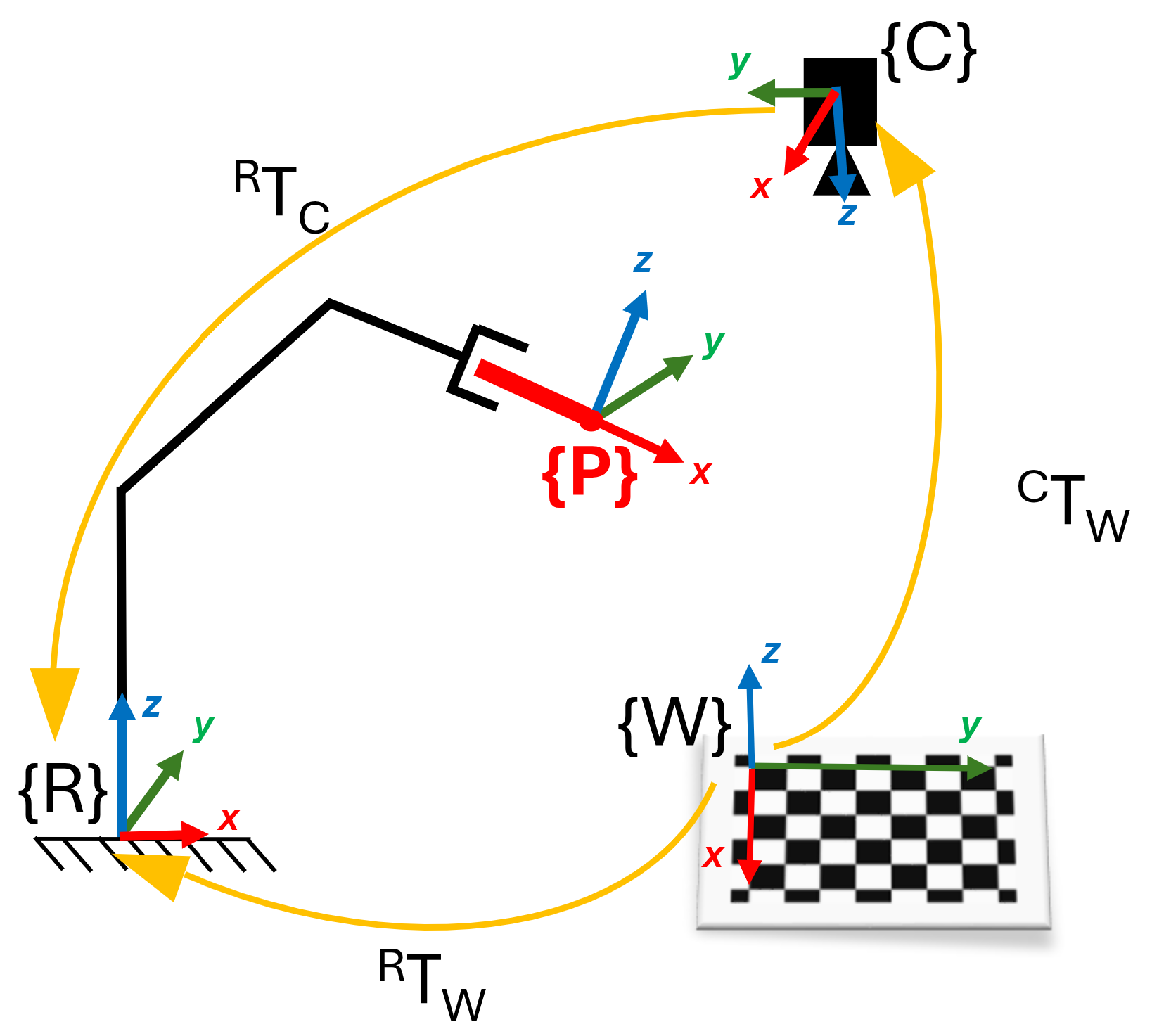
Figure 1. Robot, world, and camera coordinate frames and their transformation.
Computers 15 00053 g001
Figure 2. World coordinate frame.
Computers 15 00053 g002
Figure 3. Experimental setup including the reference frame annotation for camera, world, pointer tool, and robot.
Computers 15 00053 g003
Figure 4. Calibration board of 8 × 6 inner chessboard corners image points rendered with circles and connecting lines.
Computers 15 00053 g004
Figure 5. Pointer tool specifications (dimensions are expressed in millimetres).
Computers 15 00053 g005
Figure 6. The 12 evaluation points selected that span the area of the chessboard.
Computers 15 00053 g006
Figure 7. Live rendering of the chessboard pattern during the data collection stage of the calibration process: (a) Left camera image number 5. (b) Right camera image number 5. (c) Left camera image number 10. (d) Right camera image number 10.
Computers 15 00053 g007
Figure 8. Point cloud of the first image from the set of stereo camera calibration images.
Computers 15 00053 g008
Figure 9. Rectified rendered images of the 8 × 6 image points of the chessboard for the experiments: (ai) Experiments 2–9, respectively. (ae) Board placed flat on the workbench. (fi) Board placed inclined to the workbench. (h,i) Lower illumination environment.
Computers 15 00053 g009
Figure 10. Box plot of RMSE for x, y, and z direction in the robot coordinate frame for the 12 evaluation points for 10 experiments.
Computers 15 00053 g010
Figure 11. Qualitative evaluation of the hand-to-eye calibration process: (ac) Rendered image of the detection of the inner grid points of the chessboard, including the 12 evaluation points. (df) Point cloud visualising the image in the camera coordinate. (gi) ROS2 implementation of the 12 evaluation points in the robot coordinate.
Computers 15 00053 g011
Table 1. UR10e Denavit–Hartenberg parameters.
Jointa (Metres)d (Metres) α (Radians)
100.1807 π / 2
2−0.612700
3−0.5715500
400.17415 π / 2
500.11985 π / 2
600.116550
Table 2. Results of projecting image points and disparity values to the camera coordinate frame and from the camera coordinate to the robot coordinate.
Image PlaneCamera Coordinate { C } (mm)Robot Coordinate { R } (mm)
Point u v d x c y c z c x r y r z r
125784115.94−56.76−105.9490.43825−47313
252385118216.03−102.55481.861055.53−326.8713
3519275116.69214.1992.69487.281160.55−491.5512.85
4255270114.94−59.1288.58494.7929.18−637.2914
5294122116−18.08−66.39490.16878.99−48513.09
6484123117.12176.99−64.38485.461043.62−380.2411.66
7481237116.69175.1652.66487.281105.98−479.313.02
8293233115.25−19.7650.03493.35941.13−583.5113.06
9331159115.6220.2−27.17491.75932.48−497.0511.33
10445161116.75137.27−25.48487.021031.55−434.5112.4
11444198116.25136.9813.24489.111052.44−467.1611.35
12330197115.8819.5411.91490.69953.27−530.0913.46
Table 3. Results of calculated and actual position of the 12 points expressed in millimetres.
Point x r x act y r y act z r z act
1825825−473−4731313
21055.531055−326.87−3261312
31160.551160−491.55−49112.8513
4929.18931−637.29−63714.0013
5878.99878−485−48413.0913
61043.621043−380.24−38011.6613
71105.981107−479.3−47813.0214
8941.13942−583.51−58213.0614
9932.48934−497.05−49611.3314
101031.551032−434.51−43412.4013
111052.441052−467.16−46611.3514
12953.27954−530.09−53013.4614
Table 4. Results of RMSE values of the evaluation experiments in millimetres.
Experimentxyz
10.92640.85991.3050
21.14820.49551.9773
30.87220.57651.6440
40.70330.90241.4881
50.81240.54251.8366
60.56100.49521.5834
70.82160.92881.4217
80.62890.66622.0844
90.96750.56303.1897
100.90200.68274.1996
Disclaimer/Publisher’s Note: The statements, opinions and data contained in all publications are solely those of the individual author(s) and contributor(s) and not of MDPI and/or the editor(s). MDPI and/or the editor(s) disclaim responsibility for any injury to people or property resulting from any ideas, methods, instructions or products referred to in the content.