
Reducing Delivery Times by Utilising On-Site Wire Arc Additive Manufacturing with Digital-Twin Methods


Abstract
1. Introduction
- Reduced transport costs: Producing spare parts in comparison to ordering and delivery from overseas can reduce delivery costs by 85% [4];
- Storage and warehousing: By consolidating slow-moving and excess inventory to free up warehouse space, up to 17% of storage costs can be saved [4];
- Reduced production cost: On-site production with additive technologies, in combination with subtractive post-processing, can help to reduce the consumption of raw materials. By applying the material close to the target surface with little or no excess material, the material yield can be significantly increased. Compared with production relying solely on subtractive machining, less excess waste material is produced, e.g., in the form of chips. Compared with other processes such as casting, no additional cost-intensive moulds are required. Campatelli et al. [5] provide evidence that energy savings of up to 34% are possible.
- Interdependent process parameters: In additive manufacturing, the process parameters are more demanding. For example, the temperature between two subsequent layers, often called the interlayer temperature, is a critical factor for the successful production of the component. This temperature is influenced by various aspects, including the shape of the workpiece, the material and temperature of the substrate plate, the welding parameters, control strategies, the adaptation of machining paths, simulations, measurements, and cooling methods [9,10]. Consequently, it is essential to meticulously select all other parameters with consideration given to each other;
- Complex simulation: Due to the wide variety of additive processes and the complexity of the processes compared with material removal simulations [12,13], the simulation of the additive process is still under research, unlike subtractive processes, where computer-aided simulation was already described in the 1980s and 1990s by van Hook and Glaeser [12,13]. These simulations have been extended to provide a full description of the mechanics during milling processes, including cutting forces [14], tool vibration, and chatter [15]. Simulation in additive processes is still under development, with approaches utilising finite element techniques [16] to simple shape estimation as in common 3D toolpath generation tools, such as [17,18,19];
- Comprehensive virtual process chain: The software tools that represent the virtual process chain must be able to handle the entire production process. This includes not only the additive part of the process, but also the post-processing, which can be heat treatment [20], milling, or other subtractive techniques [11,21] and more;
- Training and qualification: Because of the aforementioned aspects, additive processes require qualified personnel to plan and maintain the process. The training of qualified professionals is a major challenge [22].
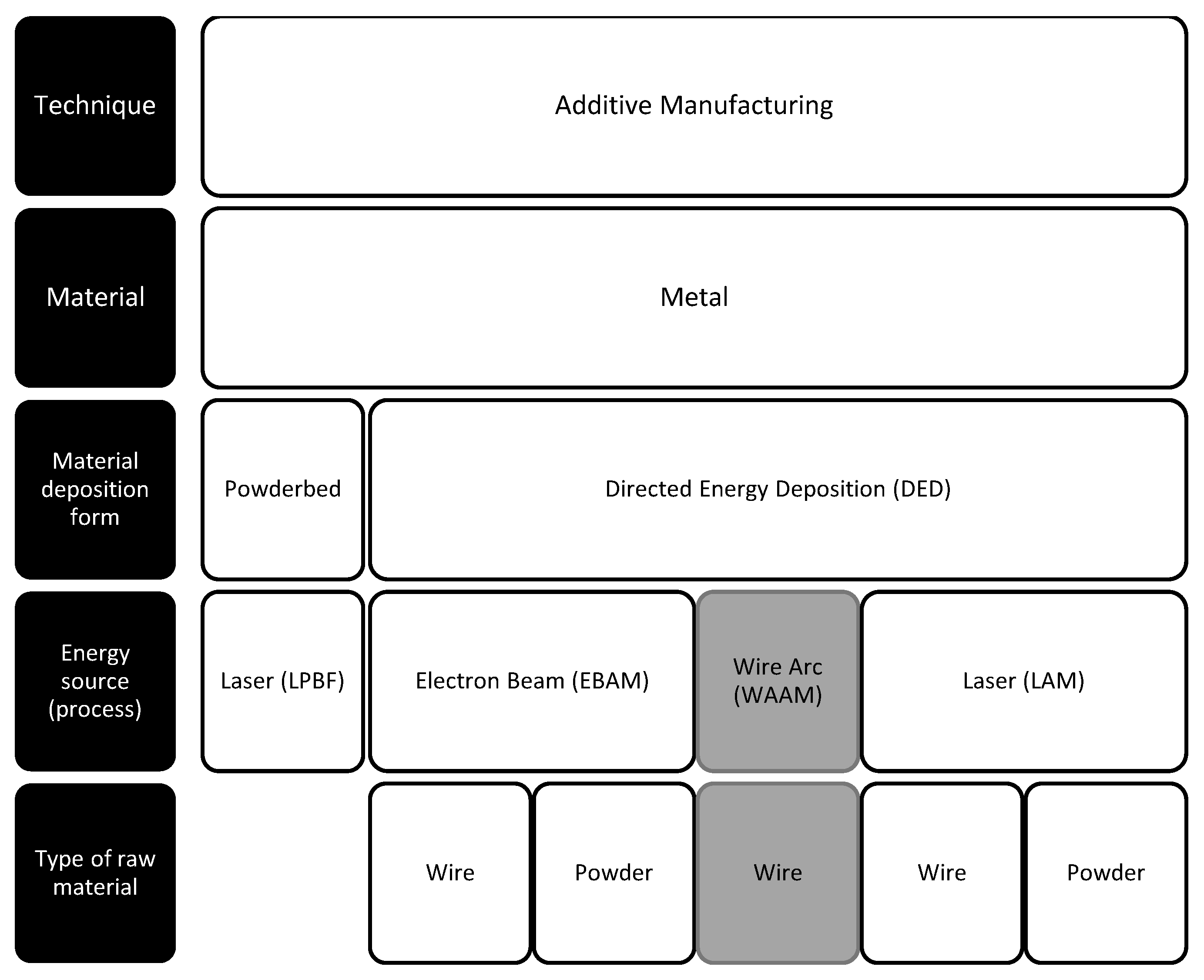
2. Overview of the Current WAAM Process
2.1. WAAM as a Process and the Benefits
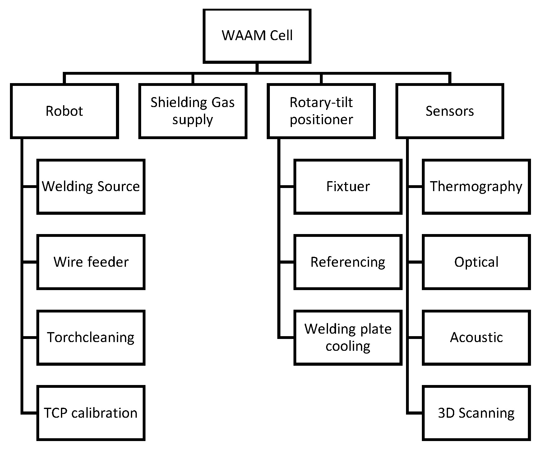
2.2. Components of a WAAM Process
2.3. Problem Description
- Process planning
- Process stability
- Standardisation and certification
2.4. Suggested Solution
3. Digital Twin Methods
3.1. Digital Twin Definition
3.2. Recent Developments of Digital Twin in Metal Additive Manufacturing
3.3. Simulation Tools in Digital Twins
3.4. Data Exchange
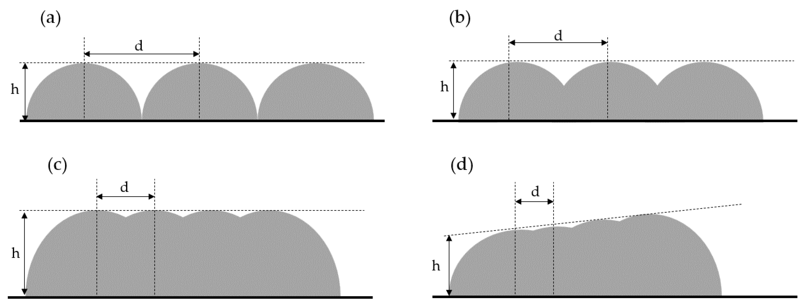
3.5. Path Planning
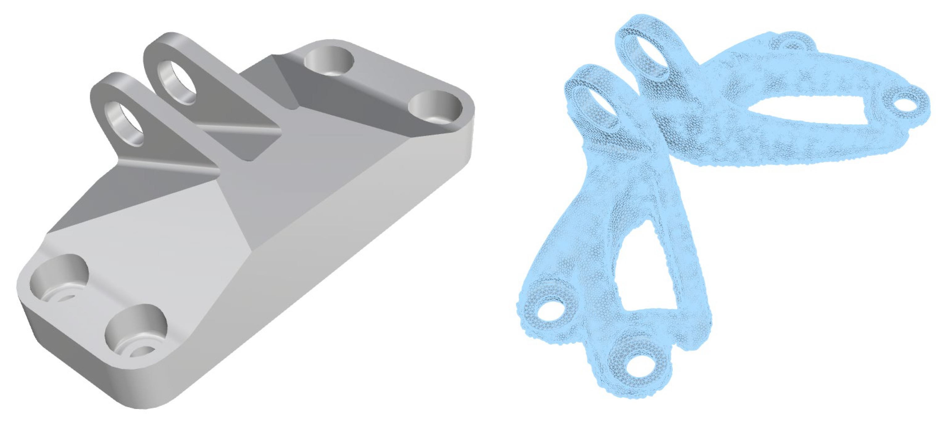
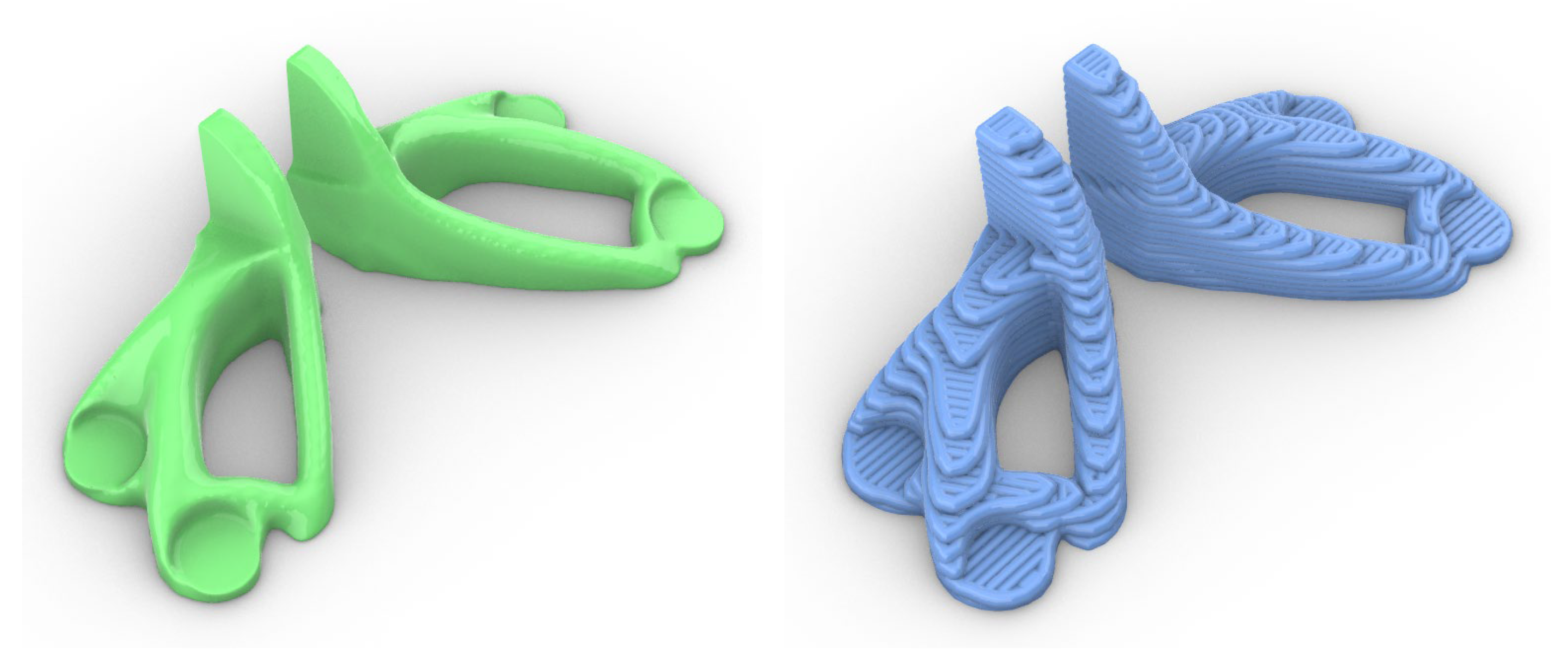
4. Real-World Sample-GE Aircraft Engine Bracket Challenge
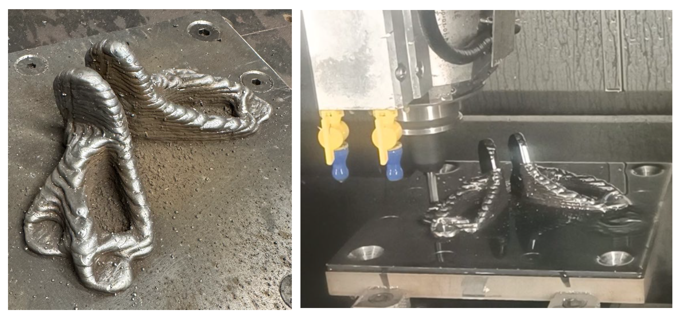
4.1. Application of WAAM to the Sample
4.2. Setup of the WAAM Cell
4.3. Applied Digital Twin Methods
4.4. Utilisation of Sensors for the Digital Shadow
4.5. CAM for WAAM
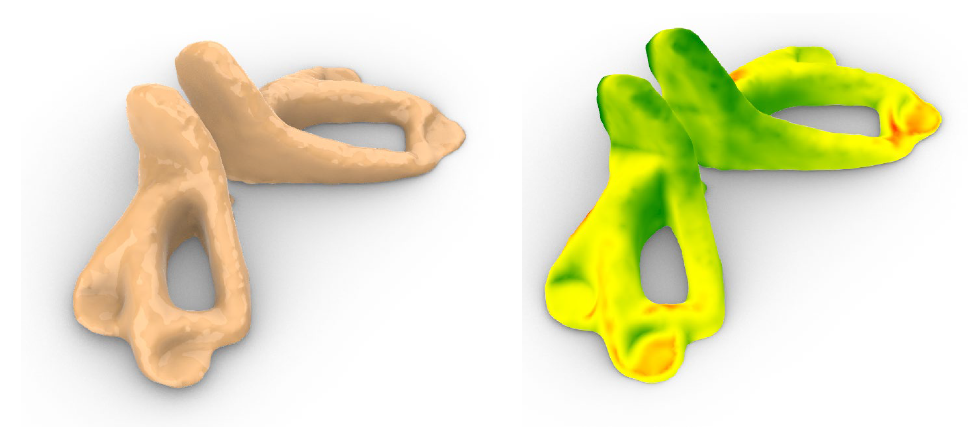
4.6. Simulation of the Part Shape and Inner Temperatures
4.7. CAM for Milling
5. Outlook
- Integration and feedback loops: Establishing a dynamic feedback system through digital twins supports continuous optimisation and improvement of the manufacturing process;
- Thermal management: Effective management of heat distribution reduces thermal gradients, minimising residual stresses and distortion in the parts produced;
- Dimensional accuracy and surface finish: Real-time adjustments ensure that the parts produced meet precise dimensional specifications and have a high-quality surface finish;
- Residual stresses and distortion: By accurately predicting and controlling stress accumulation, potential distortion in the part is minimised, improving part integrity;
- Weld direction and torch angle: Optimising weld paths and torch angles improves material flow and layer adhesion, resulting in higher-quality assemblies;
- Macroscopic material properties: Tailoring material properties through predictive simulation ensures the final product meets specific performance criteria;
- Post-processing considerations: By streamlining the manufacturing process, digital twins reduce the need for extensive post-processing, resulting in time and cost savings.
Author Contributions
Funding
Data Availability Statement
Conflicts of Interest
Abbreviations
| AM | Additive manufacturing |
| AR | Augmented reality |
| CAD | Computer-aided design |
| CAM | Computer-aided manufacturing |
| CMT | Cold metal transfer |
| CNC | Computerised numerical control |
| CNN | Convolutional neuronal network |
| DED | Direct energy deposition |
| DS | Digital shadow |
| DT | Digital twin |
| FEA | Finite element analysis |
| GMAW | Gas metal arc welding |
| GTAW | Gas tungsten arc welding |
| LPBF | Laser-based powder bed fusion |
| MAG | Metal active gas welding |
| MIG | Metal inert gas welding |
| NTWD | Nozzle to work distance |
| OME | Observable manufacturing element |
| OPC/UA | Open platform communications unified architecture |
| PAW | Plasma arc welding |
| PLC | Programmable logic controller |
| TCP | Tool centre point |
| TIG | Tungsten inert gas welding |
| TOF | Time of flight |
| TS | Torch travel speed |
| VR | Virtual reality |
| WAAM | Wire arc additive manufacturing |
| WFS | Wire feed speed |
References
- Abdelati, M.H.; Abdelwali, H.A. Evaluating the Impact of Transportation Costs, Supply Chain Reliability, and Operational Efficiency on Global Import Decisions. Int. J. Adv. Eng. Bus. Sci. 2024, 5, 1–23. [Google Scholar] [CrossRef]
- Yang, Z. The Suez Canal Blockage in March 2021: The Causation of the Incident and Its Economic and Social Influences. AEMPS 2024, 60, 185–192. [Google Scholar] [CrossRef]
- Zhuo, Q.; Qin, L.; Liu, W.; Liu, Y.; You, J. Supply chain risks and geographical supplier distribution strategy. Account. Financ. 2024, 64, 3841–3881. [Google Scholar] [CrossRef]
- Scott, A.; Harrison, T.P. Additive Manufacturing in an End-to-End Supply Chain Setting. 3D Print. Addit. Manuf. 2015, 2, 65–77. [Google Scholar] [CrossRef]
- Campatelli, G.; Montevecchi, F.; Venturini, G.; Ingarao, G.; Priarone, P.C. Integrated WAAM-Subtractive Versus Pure Subtractive Manufacturing Approaches: An Energy Efficiency Comparison. Int. J. Precis. Eng. Manuf.-Green Technol. 2020, 7, 1–11. [Google Scholar] [CrossRef]
- Nuñez Rodriguez, J.; Andrade Sosa, H.H.; Villarreal-Archila, S.M.; Ortiz, A. The Impact of Additive Manufacturing on Supply Chain Management from a System Dynamics Model—Scenario: Traditional, Centralized, and Distributed Supply Chain. Processes 2022, 10, 2489. [Google Scholar] [CrossRef]
- Nota, C.; Rückert, G.; Heuzé, J.L.; Carlino, L.; Quenez, J.M.; Courregelongue, L. A First Feedback on Manufacturing and in-Service Behaviour of a WAAM-Made Propeller for Naval Application. Available online: https://link.springer.com/article/10.1007/s40194-023-01475-w#citeas (accessed on 13 March 2025).
- Rodrigues, T.A.; Duarte, V.; Miranda, R.M.; Santos, T.G.; Oliveira, J.P. Current Status and Perspectives on Wire and Arc Additive Manufacturing (WAAM). Materials 2019, 12, 1121. [Google Scholar] [CrossRef]
- Zhai, W.; Wu, N.; Zhou, W. Effect of Interpass Temperature on Wire Arc Additive Manufacturing Using High-Strength Metal-Cored Wire. Metals 2022, 12, 212. [Google Scholar] [CrossRef]
- Wandtke, K.; Schroepfer, D.; Scharf-Wildenhain, R.; Haelsig, A.; Kannengiesser, T.; Kromm, A.; Hensel, J. Influence of the WAAM process and design aspects on residual stresses in high-strength structural steels. Weld. World 2023, 67, 987–996. [Google Scholar] [CrossRef]
- Fuchs, C.; Fritz, C.; Zaeh, M.F. Impact of wire and arc additively manufactured workpiece geometry on the milling process. Prod. Eng. Res. Dev. 2023, 17, 415–424. [Google Scholar] [CrossRef]
- van Hook, T. Real-time shaded NC milling display. ACM SIGGRAPH Comput. Graph. 1986, 20, 15–20. [Google Scholar] [CrossRef]
- Glaeser, G.; Gröller, E. Efficient Volume-Generation During the Simulation of NC-Milling. In Mathematical Visualization; Hege, H.-C., Polthier, K., Eds.; Springer: Berlin/Heidelberg, Germany, 1998; pp. 89–106. ISBN 978-3-642-08373-0. [Google Scholar]
- Cabral, G.F. Modeling and Simulation of Tool Engagement and Prediction of Process Forces in Milling. Ph.D. Thesis, Universitätsbibliothek der RWTH Aachen, Aachen, Germany, 2016. [Google Scholar]
- Surmann, T. Modelling and Visualization of the Surface Resulting from the Milling Process. In Computer Graphics; Mukai, N., Ed.; InTech: Vienna, Austria, 2012; ISBN 978-953-51-0455-1. [Google Scholar]
- Sampaio, R.; Pragana, J.; Bragança, I.; Silva, C.; Nielsen, C.V.; Martins, P. Modelling of wire-arc additive manufacturing—A review. Adv. Ind. Manuf. Eng. 2023, 6, 100121. [Google Scholar] [CrossRef]
- Alessandro, R. Contributors. Slic3r. Open Source Community. 2024. Available online: https://slic3r.org/ (accessed on 1 February 2025).
- Prusa Research. PrusaSlicer; Prusa Research, a.s: Prague, Czech Republic, 2024; Available online: https://www.prusa3d.com/page/prusaslicer_424/ (accessed on 1 February 2025).
- Ultimaker. Ultimaker Cura; Ultimaker B.V: Utrecht, The Netherlands, 2024; Available online: https://ultimaker.com/software/ultimaker-cura (accessed on 1 February 2025).
- Abdallah, S.; Pervaiz, S. Reviewing Post-Processing Techniques to Enhance Mechanical Properties of Parts Fabricated Using WAAM. In Volume 2A: Advanced Manufacturing. Proceedings of the ASME 2021 International Mechanical Engineering Congress and Exposition, Virtual, 1–5 November 2021; American Society of Mechanical Engineers: New York, NY, USA, 2021; ISBN 978-0-7918-8555-0. [Google Scholar]
- Son, H.J.; Seo, B.W.; Kim, C.J.; Kim, S.; Cho, Y.T. Coordinate system setting for post-machining of impeller shape by wire arc DED and evaluation of processing efficiency. Sci. Rep. 2024, 14, 18262. [Google Scholar] [CrossRef] [PubMed]
- Shah, A.; Aliyev, R.; Zeidler, H.; Krinke, S. A Review of the Recent Developments and Challenges in Wire Arc Additive Manufacturing (WAAM) Process. J. Manuf. Mater. Process. 2023, 7, 97. [Google Scholar] [CrossRef]
- Li, Y.; Su, C.; Zhu, J. Comprehensive review of wire arc additive manufacturing: Hardware system, physical process, monitoring, property characterization, application and future prospects. Results Eng. 2022, 13, 100330. [Google Scholar] [CrossRef]
- Athaib, N.H.; Haleem, A.H.; Al-Zubaidy, B. A review of Wire Arc Additive Manufacturing (WAAM) of Aluminium Composite, Process, Classification, Advantages, Challenges, and Application. J. Phys. Conf. Ser. 2021, 1973, 12083. [Google Scholar] [CrossRef]
- Thomas, D.S.; Gilbert, S.W. Costs and Cost Effectiveness of Additive Manufacturing; NIST Special Publication: Gaithersburg, MD, USA, 2014. [Google Scholar]
- Khanna, N.; Salvi, H.; Karaş, B.; Fairoz, I.; Shokrani, A. Cost Modelling for Powder Bed Fusion and Directed Energy Deposition Additive Manufacturing. J. Manuf. Mater. Process. 2024, 8, 142. [Google Scholar] [CrossRef]
- Sames, W.J.; List, F.A.; Pannala, S.; Dehoff, R.R.; Babu, S.S. The metallurgy and processing science of metal additive manufacturing. Int. Mater. Rev. 2016, 61, 315–360. [Google Scholar] [CrossRef]
- Wang, J.F.; Sun, Q.J.; Wang, H.; Liu, J.P.; Feng, J.C. Effect of location on microstructure and mechanical properties of additive layer manufactured Inconel 625 using gas tungsten arc welding. Mater. Sci. Eng. A 2016, 676, 395–405. [Google Scholar] [CrossRef]
- Wang, H.; Jiang, W.; Ouyang, J.; Kovacevic, R. Rapid prototyping of 4043 Al-alloy parts by VP-GTAW. J. Mater. Process. Technol. 2004, 148, 93–102. [Google Scholar] [CrossRef]
- Geng, H.; Li, J.; Xiong, J.; Lin, X.; Zhang, F. Optimization of wire feed for GTAW based additive manufacturing. J. Mater. Process. Technol. 2017, 243, 40–47. [Google Scholar] [CrossRef]
- Wang, F.; Williams, S.; Colegrove, P.; Antonysamy, A.A. Microstructure and Mechanical Properties of Wire and Arc Additive Manufactured Ti-6Al-4V. Metall. Mater. Trans. A 2013, 44, 968–977. [Google Scholar] [CrossRef]
- Ding, D.; Pan, Z.; Cuiuri, D.; Li, H. Wire-feed additive manufacturing of metal components: Technologies, developments and future interests. Int. J. Adv. Manuf. Technol. 2015, 81, 465–481. [Google Scholar] [CrossRef]
- Nie, Y.; Zhang, P.; Wu, X.; Li, G.; Yan, H.; Yu, Z. Rapid prototyping of 4043 Al-alloy parts by cold metal transfer. Sci. Technol. Weld. Join. 2018, 23, 527–535. [Google Scholar] [CrossRef]
- Caballero, A.; Ding, J.; Ganguly, S.; Williams, S. Wire + Arc Additive Manufacture of 17-4 PH stainless steel: Effect of different processing conditions on microstructure, hardness, and tensile strength. J. Mater. Process. Technol. 2019, 268, 54–62. [Google Scholar] [CrossRef]
- Lin, J.; Lv, Y.; Liu, Y.; Sun, Z.; Wang, K.; Li, Z.; Wu, Y.; Xu, B. Microstructural evolution and mechanical property of Ti-6Al-4V wall deposited by continuous plasma arc additive manufacturing without post heat treatment. J. Mech. Behav. Biomed. Mater. 2017, 69, 19–29. [Google Scholar] [CrossRef]
- Williams, S.W.; Martina, F.; Addison, A.C.; Ding, J.; Pardal, G.; Colegrove, P. Wire + Arc Additive Manufacturing. Mater. Sci. Technol. 2016, 32, 641–647. [Google Scholar] [CrossRef]
- Karpagaraj, A.; Baskaran, S.; Arunnellaiappan, T.; Kumar, N.R. A review on the suitability of wire arc additive manufacturing (WAAM) for stainless steel 316. In Advances in Mechanical Design, Materials and Manufacture: Proceeding of the Second International Conference on Design, Materials and Manufacture (ICDEM 2019), Surathkal, India, 6–8 December 2019; AIP Publishing: New York, NY, USA, 2019; p. 50001. [Google Scholar]
- Vartanian, K.; Brewer, L.; Manley, K.; Cobbs, T. Powder Bed Fusion vs. Directed Energy Deposition Benchmark Study: Mid-Sizepart with Simple Geometry. Available online: https://www.optomec.com/wp-content/uploads/2018/06/PBF-vs-DED-BENCHMARK-STUDY_7March_2018-03.pdf (accessed on 18 February 2025).
- Tabernero, I.; Paskual, A.; Álvarez, P.; Suárez, A. Study on Arc Welding Processes for High Deposition Rate Additive Manufacturing. Procedia CIRP 2018, 68, 358–362. [Google Scholar] [CrossRef]
- Reisch, R.T.; Hauser, T.; Lutz, B.; Tsakpinis, A.; Winter, D.; Kamps, T.; Knoll, A. Context awareness in process monitoring of additive manufacturing using a digital twin. Int. J. Adv. Manuf. Technol. 2022, 119, 3483–3500. [Google Scholar] [CrossRef]
- Maffia, S.; Chiappini, F.; Maggiani, G.; Furlan, V.; Guerrini, M.; Previtali, B. Comparison between Eight-Axis Articulated Robot and Five-Axis CNC Gantry Laser Metal Deposition Machines for Fabricating Large Components. Appl. Sci. 2023, 13, 5259. [Google Scholar] [CrossRef]
- Cunningham, C.R.; Flynn, J.M.; Shokrani, A.; Dhokia, V.; Newman, S.T. Invited review article: Strategies and processes for high quality wire arc additive manufacturing. Addit. Manuf. 2018, 22, 672–686. [Google Scholar] [CrossRef]
- Kerber, E.; Fahrendholz, J.L.; Brell-Cokcan, S.; Dewald, P.; Sharma, R.; Reisgen, U. Dynamic WAAM: Adaptive processes for equivalent contact surface (ECS) optimization. Constr. Robot. 2023, 7, 309–328. [Google Scholar] [CrossRef]
- Yuan, L.; Pan, Z.; Ding, D.; Yu, Z.; van Duin, S.; Li, H.; Li, W.; Norrish, J. Fabrication of metallic parts with overhanging structures using the robotic wire arc additive manufacturing. J. Manuf. Process. 2021, 63, 24–34. [Google Scholar] [CrossRef]
- Li, B.; Nagaraja, K.M.; Zhang, R.; Malik, A.; Lu, H.; Li, W. Integrating robotic wire arc additive manufacturing and machining: Hybrid WAAM machining. Int. J. Adv. Manuf. Technol. 2023, 129, 3247–3259. [Google Scholar] [CrossRef]
- Segovia, M.; Garcia-Alfaro, J. Design, Modeling and Implementation of Digital Twins. Sensors 2022, 22, 5396. [Google Scholar] [CrossRef]
- Qi, Q.; Tao, F. Digital Twin and Big Data Towards Smart Manufacturing and Industry 4.0: 360 Degree Comparison. IEEE Access 2018, 6, 3585–3593. [Google Scholar] [CrossRef]
- Cho, Y.; Noh, S.D. Design and Implementation of Digital Twin Factory Synchronized in Real-Time Using MQTT. Machines 2024, 12, 759. [Google Scholar] [CrossRef]
- Hirono, Y.; Mori, T.; Sugimoto, S.; Miyata, Y. Investigation on influence of thermal history on quality of workpiece created by directed energy deposition. CIRP Ann. 2024, 73, 133–136. [Google Scholar] [CrossRef]
- ISO 15926-1:2004; Industrial Automation Systems and Integration—Integration of Life-Cycle Data for Process Plants Including Oil and Gas Production Facilities. ISO International Organization for Standardization: Geneva, Switzerland, 2004.
- IEC 62443-1-1:2009; Industrial Communication Networks. Network and System Security. Terminology, Concepts and Models. British Standards Institution: London, UK, 2009.
- Shafto, M.; Conroy, M.; Doyle, R.; Glaessgen, E.; Kemp, C.; LeMoigne, J.; Wang, L. NASA Modeling, Simulation. In Information Technology & Processing—TA11; NASA: Washington, DC, USA, 2010. [Google Scholar]
- Errandonea, I.; Beltrán, S.; Arrizabalaga, S. Digital Twin for maintenance: A literature review. Comput. Ind. 2020, 123, 103316. [Google Scholar] [CrossRef]
- Zhang, X.; Wu, B.; Zhang, X.; Duan, J.; Wan, C.; Hu, Y. An effective MBSE approach for constructing industrial robot digital twin system. Robot. Comput.-Integr. Manuf. 2023, 80, 102455. [Google Scholar] [CrossRef]
- Fuller, A.; Fan, Z.; Day, C.; Barlow, C. Digital Twin: Enabling Technologies, Challenges and Open Research. IEEE Access 2020, 8, 108952–108971. [Google Scholar] [CrossRef]
- ISO 23247-1:2021; Automation Systems and Integration—Digital Twin Framework for Manufacturing—Overview and General Principles. ISO International Organization for Standardization: Geneva, Switzerland, 2021.
- Bong Kim, D.; Shao, G.; Jo, G. A digital twin implementation architecture for wire + arc additive manufacturing based on ISO 23247. Manuf. Lett. 2022, 34, 1–5. [Google Scholar] [CrossRef]
- Mu, H.; He, F.; Yuan, L.; Hatamian, H.; Commins, P.; Pan, Z. Online distortion simulation using generative machine learning models: A step toward digital twin of metallic additive manufacturing. J. Ind. Inf. Integr. 2024, 38, 100563. [Google Scholar] [CrossRef]
- Kang, M.-S.; Lee, D.-H.; Bajestani, M.S.; Kim, D.B.; Noh, S.D. Edge Computing-Based Digital Twin Framework Based on ISO 23247 for Enhancing Data Processing Capabilities. Machines 2025, 13, 19. [Google Scholar] [CrossRef]
- Mahdi, M.M.; Bajestani, M.S.; Noh, S.D.; Kim, D.B. Digital twin-based architecture for wire arc additive manufacturing using OPC UA. Robot. Comput.-Integr. Manuf. 2025, 94, 102944. [Google Scholar] [CrossRef]
- Karkaria, V.; Goeckner, A.; Zha, R.; Chen, J.; Zhang, J.; Zhu, Q.; Cao, J.; Gao, R.X.; Chen, W. Towards a digital twin framework in additive manufacturing: Machine learning and bayesian optimization for time series process optimization. J. Manuf. Syst. 2024, 75, 322–332. [Google Scholar] [CrossRef]
- Bevans, B.D.; Carrington, A.; Riensche, A.; Tenequer, A.; Barrett, C.; Halliday, H.; Srinivasan, R.; Cole, K.D.; Rao, P. Digital twins for rapid in-situ qualification of part quality in laser powder bed fusion additive manufacturing. Addit. Manuf. 2024, 93, 104415. [Google Scholar] [CrossRef]
- Kong, T.; Hu, T.; Zhou, T.; Ye, Y. Data Construction Method for the Applications of Workshop Digital Twin System. J. Manuf. Syst. 2021, 58, 323–328. [Google Scholar] [CrossRef]
- Grieves, M. Digital twin: Manufacturing excellence through virtual factory replication. White Pap. 2014, 1, 1–7. [Google Scholar]
- White, K.P.; Ingalls, R.G. Introduction to simulation. In Proceedings of the 2009 Winter Simulation Conference—(WSC 2009), Austin, TX, USA, 13–16 December 2009; IEEE: New York, NY, USA, 2009; pp. 12–23, ISBN 978-1-4244-5770-0. [Google Scholar]
- Mills, J.K.; Nguyen, C.V. Robotic Manipulator Collisions: Modeling and Simulation. J. Dyn. Sys. Meas. Control 1992, 114, 650–659. [Google Scholar] [CrossRef]
- Khatib, O.; Yokoi, K.; Brock, O.; Chang, K.; Casal, A. Robots in human environments. In Proceedings of the First Workshop on Robot Motion and Control. RoMoCo’99 (Cat. No.99EX353), Kiekrz, Poland, 29 June 1999; IEEE: New York, NY, USA, 1999; pp. 213–221, ISBN 0-7803-5655-1. [Google Scholar]
- Heisenberg, G.; Göbel, M.; Hambürger, T.; Hornung, N.; Klein, U.; Nikitin, I.; Rattay, O.; Scharping, J.; Troche, K.; Wienss, C. Realtime dynamics simulation of cables, hoses and wiring harnesses for high accuracy digital mockups and load analysis. In Proceedings of the Automotive Power Electronics, Paris, France, 26–27 September 2007. [Google Scholar]
- FormTec GmbH. FormTec NCSpeed: Optimization and Simulation for CNC Machining; FormTec GmbH: Dornstetten, Germany, 2025. [Google Scholar]
- MachineWorks Ltd. MachineWorks: Simulation & Verification Software for CNC Machining; MachineWorks Ltd.: Sheffield, UK, 2025. [Google Scholar]
- ModuleWorks GmbH. ModuleWorks CutSim: Real-Time Material Removal Simulation; ModuleWorks GmbH: Aachen, Germany, 2025. [Google Scholar]
- Korneev, S.; Wang, Z.; Thiagarajan, V.; Nelaturi, S. Fabricated shape estimation for additive manufacturing processes with uncertainty. Comput.-Aided Des. 2020, 127, 102852. [Google Scholar] [CrossRef]
- Cao, Y.; Zhu, S.; Liang, X.; Wang, W. Overlapping model of beads and curve fitting of bead section for rapid manufacturing by robotic MAG welding process. Robot. Comput.-Integr. Manuf. 2011, 27, 641–645. [Google Scholar] [CrossRef]
- Söntgen, J. FEM Basierte Simulation des WAAM-Prozesses mit Ansys-Mechanical. Bachelor’s Thesis, Hochschule Ruhr-West, Mülheim an der Ruhr, Germany, 2024. [Google Scholar]
- Phua, A.; Davies, C.; Delaney, G.W. A digital twin hierarchy for metal additive manufacturing. Comput. Ind. 2022, 140, 103667. [Google Scholar] [CrossRef]
- Ben Amor, S.; Elloumi, N.; Eltaief, A.; Louhichi, B.; Alrasheedi, N.H.; Seibi, A. Digital Twin Implementation in Additive Manufacturing: A Comprehensive Review. Processes 2024, 12, 1062. [Google Scholar] [CrossRef]
- Liu, C.; Vengayil, H.; Lu, Y.; Xu, X. A Cyber-Physical Machine Tools Platform using OPC UA and MTConnect. J. Manuf. Syst. 2019, 51, 61–74. [Google Scholar] [CrossRef]
- Reisch, R.; Hauser, T.; Kamps, T.; Knoll, A. Robot Based Wire Arc Additive Manufacturing System with Context-Sensitive Multivariate Monitoring Framework. Procedia Manuf. 2020, 51, 732–739. [Google Scholar] [CrossRef]
- Plakhotnik, D.; Glasmacher, L.; Vaneker, T.; Smetanin, Y.; Stautner, M.; Murtezaoglu, Y.; van Houten, F. CAM planning for multi-axis laser additive manufacturing considering collisions. CIRP Ann. 2019, 68, 447–450. [Google Scholar] [CrossRef]
- Tabernero, I.; Calleja, A.; Lamikiz, A.; López de Lacalle, L.N. Optimal Parameters for 5-axis Laser Cladding. Procedia Eng. 2013, 63, 45–52. [Google Scholar] [CrossRef]
- Ding, D.; Pan, Z.; Cuiuri, D.; Li, H. A multi-bead overlapping model for robotic wire and arc additive manufacturing (WAAM). Robot. Comput.-Integr. Manuf. 2015, 31, 101–110. [Google Scholar] [CrossRef]
- Ding, D.; Shen, C.; Pan, Z.; Cuiuri, D.; Li, H.; Larkin, N.; van Duin, S. Towards an automated robotic arc-welding-based additive manufacturing system from CAD to finished part. Comput.-Aided Des. 2016, 73, 66–75. [Google Scholar] [CrossRef]
- Venturini, G.; Montevecchi, F.; Scippa, A.; Campatelli, G. Optimization of WAAM Deposition Patterns for T-crossing Features. Procedia CIRP 2016, 55, 95–100. [Google Scholar] [CrossRef]
- Carter, W.T.; Emo, D.J.; Abbott, D.H.; Bruck, C.E.; Wilson, G.H.; Wolfe, J.B.; Finkhousen, D.M.; Tepper, A.; Stevens, R.G. The GE Aircraft Engine Bracket Challenge: An Experiment in Crowdsourcing for Mechanical Design Concepts; University of Texas at Austin: Austin, TX, USA, 2014. [Google Scholar]
- Tyflopoulos, E.; Steinert, M. Combining Macro- and Mesoscale Optimization: A Case Study of the General Electric Jet Engine Bracket. Designs 2021, 5, 77. [Google Scholar] [CrossRef]
- Gülbahçe, E.; Sezgen, H.Ç.; Çakan, A. Topology Design and Modal Analysis of a Bracket via FEA. Appl. Eng. Lett. 2019, 4, 102–105. [Google Scholar] [CrossRef]
- Rafinex. Möbius: Optimize Robust Topologies. Available online: https://rafinex.com/products/ (accessed on 25 February 2025).
- Wang, Z.; Han, K.; Tiwari, P. Digital Twin Simulation of Connected and Automated Vehicles with the Unity Game Engine. In Proceedings of the 2021 IEEE 1st International Conference on Digital Twins and Parallel Intelligence (DTPI), Beijing, China, 15 July–15 August 2021; IEEE: New York, NY, USA, 2021. [Google Scholar]
- Bevans, B.; Ramalho, A.; Smoqi, Z.; Gaikwad, A.; Santos, T.G.; Rao, P.; Oliveira, J.P. Monitoring and flaw detection during wire-based directed energy deposition using in-situ acoustic sensing and wavelet graph signal analysis. Mater. Des. 2023, 225, 111480. [Google Scholar] [CrossRef]
- Wang, Z.; Zimmer-Chevret, S.; Léonard, F.; Abba, G. Prediction of bead geometry with consideration of interlayer temperature effect for CMT-based wire-arc additive manufacturing. Weld. World 2021, 65, 2255–2266. [Google Scholar] [CrossRef]
- Baier, D.; Wolf, F.; Weckenmann, T.; Lehmann, M.; Zaeh, M.F. Thermal process monitoring and control for a near-net-shape Wire and Arc Additive Manufacturing. Prod. Eng. Res. Dev. 2022, 16, 811–822. [Google Scholar] [CrossRef]
- Panicker, S.; Nagarajan, H.P.; Tuominen, J.; Patnamsetty, M.; Coatanéa, E.; Haapala, K.R. Investigation of thermal influence on weld microstructure and mechanical properties in wire and arc additive manufacturing of steels. Mater. Sci. Eng. A 2022, 853, 143690. [Google Scholar] [CrossRef]
- Uyen, T.M.T.; Minh, P.S.; Nguyen, V.-T.; Do, T.T.; Nguyen, V.T.; Le, M.-T.; van Nguyen, T.T. Trajectory Strategy Effects on the Material Characteristics in the WAAM Technique. Micromachines 2023, 14, 827. [Google Scholar] [CrossRef]
- Zhao, Y.; Jia, Y.; Chen, S.; Shi, J.; Li, F. Process planning strategy for wire-arc additive manufacturing: Thermal behavior considerations. Addit. Manuf. 2020, 32, 100935. [Google Scholar] [CrossRef]
- Mauthner, G.; Stautner, M.; Sell, S.; Frings, M.; Lorenz, A.; Plakhotnik, D.; Bleicher, F. Wire-Arc Additive Manufacturing Toolpath Optimization Using a Dexel-Based Temperature Prediction Model. In Sustainable Manufacturing as a Driver for Growth; Kohl, H., Seliger, G., Dietrich, F., Mur, S., Eds.; Springer Nature: Cham, Switzerland, 2025; pp. 730–737. ISBN 978-3-031-77428-7. [Google Scholar]


Disclaimer/Publisher’s Note: The statements, opinions and data contained in all publications are solely those of the individual author(s) and contributor(s) and not of MDPI and/or the editor(s). MDPI and/or the editor(s) disclaim responsibility for any injury to people or property resulting from any ideas, methods, instructions or products referred to in the content. |
© 2025 by the authors. Licensee MDPI, Basel, Switzerland. This article is an open access article distributed under the terms and conditions of the Creative Commons Attribution (CC BY) license (https://creativecommons.org/licenses/by/4.0/).
Share and Cite
Sell, S.; Villani, K.; Stautner, M. Reducing Delivery Times by Utilising On-Site Wire Arc Additive Manufacturing with Digital-Twin Methods. Computers 2025, 14, 221. https://doi.org/10.3390/computers14060221
Sell S, Villani K, Stautner M. Reducing Delivery Times by Utilising On-Site Wire Arc Additive Manufacturing with Digital-Twin Methods. Computers. 2025; 14(6):221. https://doi.org/10.3390/computers14060221
Chicago/Turabian StyleSell, Stefanie, Kevin Villani, and Marc Stautner. 2025. "Reducing Delivery Times by Utilising On-Site Wire Arc Additive Manufacturing with Digital-Twin Methods" Computers 14, no. 6: 221. https://doi.org/10.3390/computers14060221
APA StyleSell, S., Villani, K., & Stautner, M. (2025). Reducing Delivery Times by Utilising On-Site Wire Arc Additive Manufacturing with Digital-Twin Methods. Computers, 14(6), 221. https://doi.org/10.3390/computers14060221