Article

Multispectral Image Generation from RGB Based on WSL Color Representation: Wavelength, Saturation, and Lightness

Department of Computer Science and Engineering, Faculty of Applied Science, University of West Bohemia, CZ 301 00 Pilsen, Czech Republic
Computers 2023, 12(9), 182; https://doi.org/10.3390/computers12090182
Submission received: 9 August 2023 / Revised: 6 September 2023 / Accepted: 8 September 2023 / Published: 13 September 2023

Abstract

:
Image processing techniques are based nearly exclusively on RGB (red–green–blue) representation, which is significantly influenced by technological issues. The RGB triplet represents a mixture of the wavelength, saturation, and lightness values of light. It leads to unexpected chromaticity artifacts in processing. Therefore, processing based on the wavelength, saturation, and lightness should be more resistant to the introduction of color artifacts. The proposed process of converting RGB values to corresponding wavelengths is not straightforward. In this contribution, a novel simple and accurate method for extracting the wavelength, saturation, and lightness of a color represented by an RGB triplet is described. The conversion relies on the known RGB values of the rainbow spectrum and accommodates variations in color saturation.

1. Introduction

Color images are widely used and processed in various fields, particularly in image processing, where essential features are extracted. Recently developed methods for image processing, e.g., edge detection, filtering, image enhancement, etc., process monochromatic images. Due to technological advances, color-acquiring devices are more or less standard. They are used in image capture and processing, computer vision, surveillance, satellites, and aerial applications in the civil, military, and space fields. The RGB (red–green–blue) representation is used nearly exclusively. The BMP, JPEG, or RAW formats are used for storing and processing nearly exclusively.
It is well known that the RGB representation only captures a fraction of the natural colors found in the rainbow spectrum [1,2,3,4,5,6,7,8,9,10,11,12,13,14,15,16,17].
Interestingly, accurately computing the wavelength λ of a color c given in RGB (red–green–blue) is not a simple task. Images are captured using the Bayer array and primarily stored in the RAW format at the best of the camera sensor’s performance. The Bayer array is usually formed as four color filters in configurations B G G R , R G B G , or R G G B [18,19,20,21]. However, images are converted to the JPEG format due to data compression, which is lossy and introduces some color artifacts. Wavelength representation is used in many applications, e.g., processing of satellite multispectral images [22,23,24], vegetation production [25,26,27], object detection [28], spatial image processing [29], and underwater image processing [30], etc.
The common approach involves converting RGB values to HLS (hue–saturation–lightness), HSV (hue–saturation–value), or similar color systems and estimating the wavelength from the hue value, which tends to be quite inaccurate.
To address this issue, our contribution proposes a precise method for computing the wavelength λ , saturation S, and lightness L by resampling the spectral rainbow curve with 100% color saturation. The rainbow curve RGB samples are given in Table A1 with a precision of 5 nm (the RGB table with 1 nm wavelength precision is available on request).
To facilitate the computation, we perform preprocessing to create a look-up table encompassing the entire wavelength range, independent of specific images. This allows efficient run-time computation and accurate extraction of the wavelength using the look-up table.
The proposed algorithm uses projective geometric algebra [16,31,32].

2. Projective Space and Duality

The projective extension of Euclidean space is not a part of standard computer science courses. However, homogeneous coordinates are used in computer graphics and computer vision algorithms, as they enable representation of geometric transformations like translation and rotation by matrix multiplication and also are able to represent a point in infinity.
The mutual conversion between Euclidean space and projective space in the case of the E 2 space can be achieved using:
X = x w Y = y w w 0
where X = ( X , Y ) , i.e., x = [ x , y : w ] T are coordinates in the Euclidean space E 2 , i.e., in the projective space P 2 . The extension to the E 3 is straightforward.
The geometrical interpretation of the Euclidean and the projective spaces is presented in Figure 1.
It should be noted that a distance of a point X = ( X , Y ) , i.e., x = [ x , y : w ] T , from a line p in the E 2 is defined as:
d i s t = a X + b Y + c a 2 + b 2 = a x + b y + c w w a 2 + b 2 , p = [ a , b : c ] T
where n = ( a , b ) is the normal vector (actually it is a bivector) of the line p and c is related to the orthogonal distance of the line p from the origin. In the E 3 case:
d i s t = a X + b Y + c Z + d a 2 + b 2 + c 2 = a x + b y + c z + d w w a 2 + b 2 + c 2 , p = [ a , b , c : d ] T
where n = ( a , b , c ) is the normal vector (actually it is a bivector) of a plane ρ and d is related to the orthogonal distance of a plane ρ from the origin.

Principle of Duality

A line p given by two points x A = [ x A , y A : w A ] T , x B = [ x B , y B : w B ] T is given using the outer product as (in this case, the outer product is formally equivalent to the cross product):
p = x A x B = i j k x A y A w A x B y B w B = i j k X A Y A 1 X B Y B 1 [ y A w B y B w A , ( x A w B x B w A ) : x A y B x B y A ] T = [ a , b : c ] T
where w A > 0 , w B > 0 , p = [ a , b : c ] T are coefficients of the line p, and i , j , k are the orthonormal basis vectors of the projective space [33]. There is a direct connection with the geometric product, which is defined as a b = a · b + a b , i.e., a b = a · b + a × b .
The projective extension of the Euclidean space enables the use of the principle of duality for the intersection of two lines p 1 and p 2 in E 2 using the outer product:
x = p 1 p 2 = i j k a 1 b 1 c 1 a 2 b 2 c 2 = [ b 1 c 2 b 2 c 1 , ( a 1 c 2 a 2 c 1 ) : a 1 b 2 a 2 b 1 ] T = [ x , y : w ] T
This is due to the fact that lines and points are dual primitives in the P 2 projective extension [34,35,36,37,38,39,40,41,42].
The outer product x A x B is equivalent to the cross product x A × x B in the P 2 projective extension case and the non-normalized normal vector of the line p is n = [ a , b : 0 ] T .
In the E 3 case, the dual primitives are points and planes, i.e.,
x = ρ 1 ρ 2 ρ 3 = i j k l a 1 b 1 c 1 d 1 a 2 b 2 c 2 d 2 a 3 b 3 c 3 d 3 = [ x , y , z : w ] T ρ = x A x B x C = i j k l x A y A z A w A x B y B z B w B x C y C z C w C = [ a , b , c : d ] T
It should be noted that the non-normalized directional vector s of the line p in E 2 is orthogonal to the normal bivector of the line, and it is given as:
s = ( X B X A , Y B Y A ) = ( s X , s Y ) = ( b , a ) , n = ( a , b )
The line p splits the E 2 plane into two half-planes:
F p ( x ) = 0 , F p ( x ) = p · x = p T x = a x + b y + c w
where w > 0 . If w ± , then the point x is close to infinity or at infinity.
It should be noted that the dot product (scalar product) is a single instruction on the GPU.

3. Color and Color Representation

Light phenomena and color understanding have been studied for a very long time. Around the year 165, Ptolemy described a wheel with different colors in the book Optics. Sir Isaac Newton (1642–1726) observed the color dispersion of light exiting an optical prism in 1666.
Newton’s contributions in the field of color dispersion stand as an indelible mark in the progression of scientific thought. In the mid-17th century, a series of experiments involving prisms and light unveiled the profound relationship between white light and its multicolored spectrum. The transformative journey of light through the prism’s material became evident as the colors elegantly unfurled, challenging prevailing assumptions and establishing a new paradigm. The work of Newton, characterized by precise observation and methodical deduction, crystallized in the form of his seminal publication Optics, which remains an enduring cornerstone of optical exploration.
The color spectrum is a continuum of colors that spans the gamut from warm reds to violets. This spectrum, which is a specific manifestation of the wavelengths of light, forms the essence of the chromatic diversity of the visible world. Each hue in the spectrum corresponds to a unique range of wavelengths within the electromagnetic spectrum, a result found in Newton’s pioneering work.
There are many ways to represent colors. They are oriented to numerical processing or user perception, some are based on linear transformations, some are highly non-linear. Other color systems are oriented toward the best color representation and reproduction in DTP (sesktop publishing) studios, etc. Also, some representations are organized as a “catalog”, e.g., color systems like Munsell and Ostwald [4,5], etc.
Probably, the most used color system in image processing is the RGB color system. It is simple and easy to use. However, it mixes different properties of light, i.e., intensity and chromaticity. This leads to chromaticity artifacts in some operations [43,44].

3.1. RGB Color System

The RGB color model encompasses both the luminosity and chromaticity aspects of colors. In this context, chromaticity is represented in a two-dimensional space, covering both the wavelength and saturation of the given color.
The wavelengths corresponding to the colors in white light are illustrated in Figure 2, with reference wavelengths of λ R = 780 nm for red, λ G = 546.1 nm for green, and λ B = 435.8 nm for blue. The RGB spectral values for iso-energetic white color are provided in Table A1 [15].
It is noteworthy that the curve for the red color exhibits partial negativity. This implies that some colors of the rainbow spectrum are not fully represented within the RGB color model, as the color is confined to the RGB cube in the range [ 0 , 1 ] × [ 0 , 1 ] × [ 0 , 1 ] .
The RGB representation is not convenient for wavelength λ determination. Another system recently used in color television broadcasts was YIQ color representation.

3.2. YIQ Color System

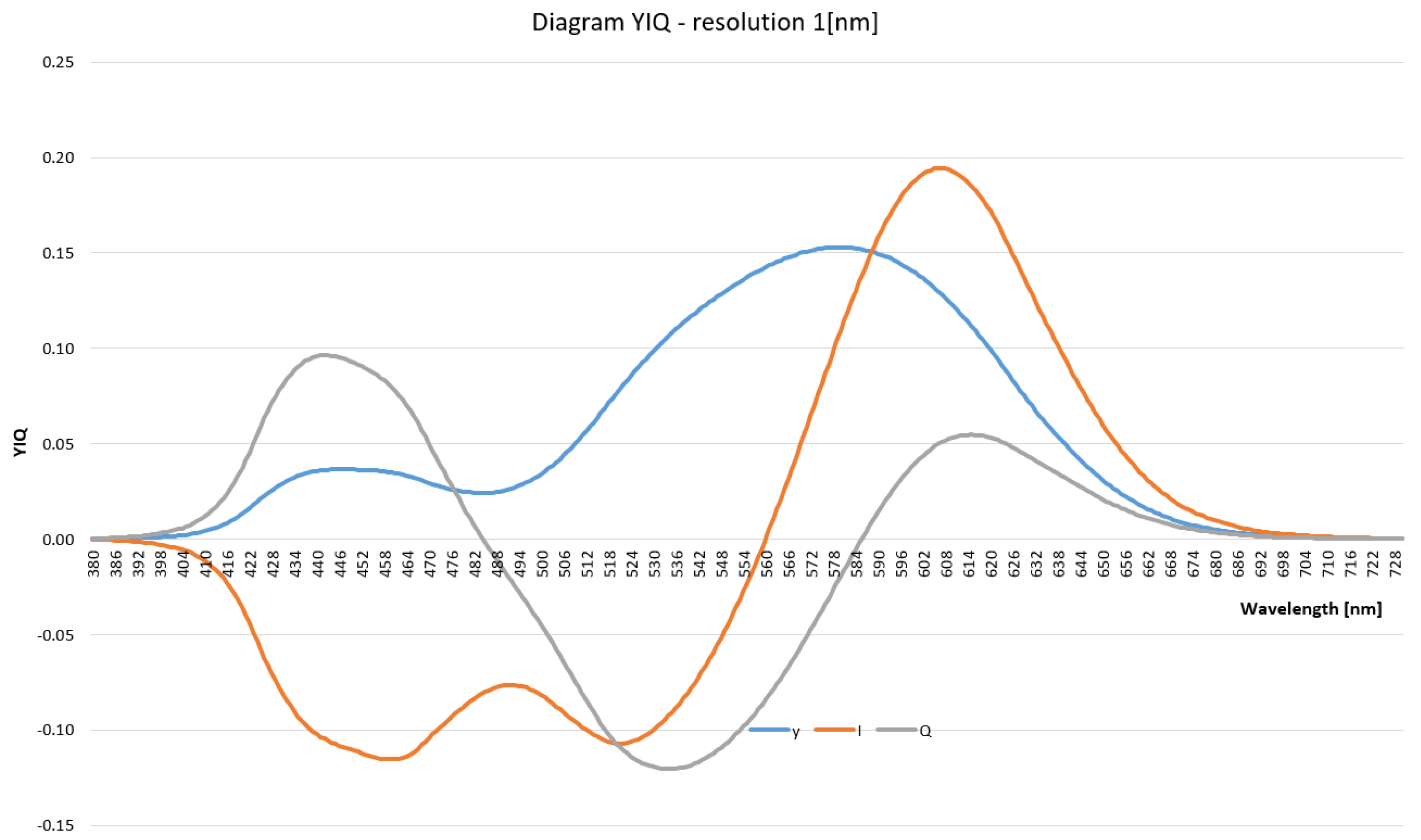
The YIQ color system [4,5,8] splits the intensity and chromaticity as the Y represents intensity, while IQ represents chromaticity. The YIQ color representation is converted from RGB by a linear transformation; see Equation (9):
Y I Q = 0.2990 0.5870 0.1140 0.5959 0.2746 0.3213 0.2115 0.5227 0.3112 R G B
Due to the conversion linearity and the huge number of pixels to be converted, the YIQ system would be seemingly preferred (the fragment (pixel) shaders on GPU could be used for significant speed-up).
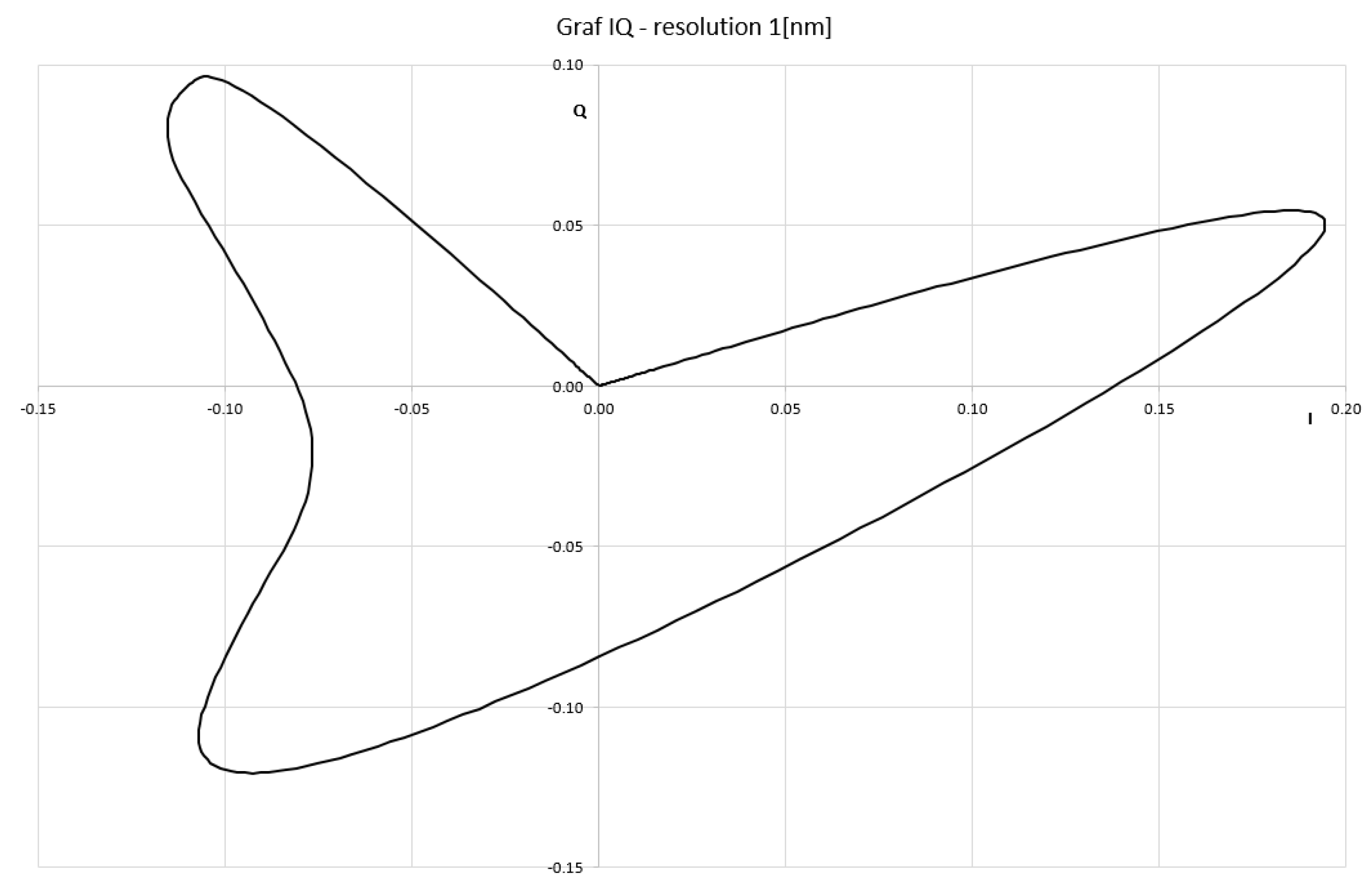
However, the chromatic coordinates of IQ change non-linearly with the wavelength λ (see Figure 3) and they are too complex to easily extract the wavelength λ (see Figure 4). It can be seen that the YIQ color system is not convenient for wavelength extraction.
There are also “user-oriented” color systems, e.g., HLS, HSV, HSI [45], etc., based on human perception, where the color is represented in a cylinder-like system.

3.3. HSI Color System

The HSI (hue–saturation–intensity) color system is a user-oriented system that belongs to the so-called HSI color model family. It was originally used to distinguish:
  • Saturation (S), represents a distance of a color c from a diagonal of the RGB cube;
  • Intensity (I) or lightness (L);
  • Hue (H), represents human color sense. The hue is represented as an angle, i.e., H [ 0 , 360 ) , where 0 , 120 , 240 represents red (R), green (G), blue (B) colors in RGB.
There are actually two HSI systems that have been used, the historical one introduced by Tektronics defined by Equations (10) and (11) in two steps, or by transformation to the HLS or HSV color systems based on RGB (with range [ 0 , 1 ] ) defined by Equation (13).
M 1 M 2 I 1 = 1 6 2 1 1 0 3 3 2 2 2 R G B
Then,
H = arctan M 1 M 2 , S = 3 2 M 1 2 + M 2 2 , I = 1 3 I 1
It should be noted that the computation of the hue H is imprecise as the ratio M 1 M 2 might be close to ± and the hue H, represented as an angle, would be imprecise or invalid (the function a r c t a n 2 should be used to avoid problems with ). The inverse transformation is defined by Equation (12)
M 1 = 2 3 S sin H , M 2 = 2 3 S cos H , I 1 = 3 I
Another HSI formulation was given in Plataniotis [46], and applied in Ma [47]. The conversion from RGB to HSI (range [ 0 , 1 ] ) is non-linear and complex.
θ = arccos ( R G ) + ( R B ) 2 ( R G ) 2 + ( R B ) ( G B ) H = θ if B G 360 θ if G > B , S = 1 3 m i n { R , G , B } R + G + B , I = R + G + B 3
The inverse transformation can be found in [46].
However, both HSI representations are computationally expensive and highly non-linear. Therefore, direct wavelength computation from RGB respecting all rainbow colors is more appropriate for precise wavelength computation.

3.4. CIE-xy Color System

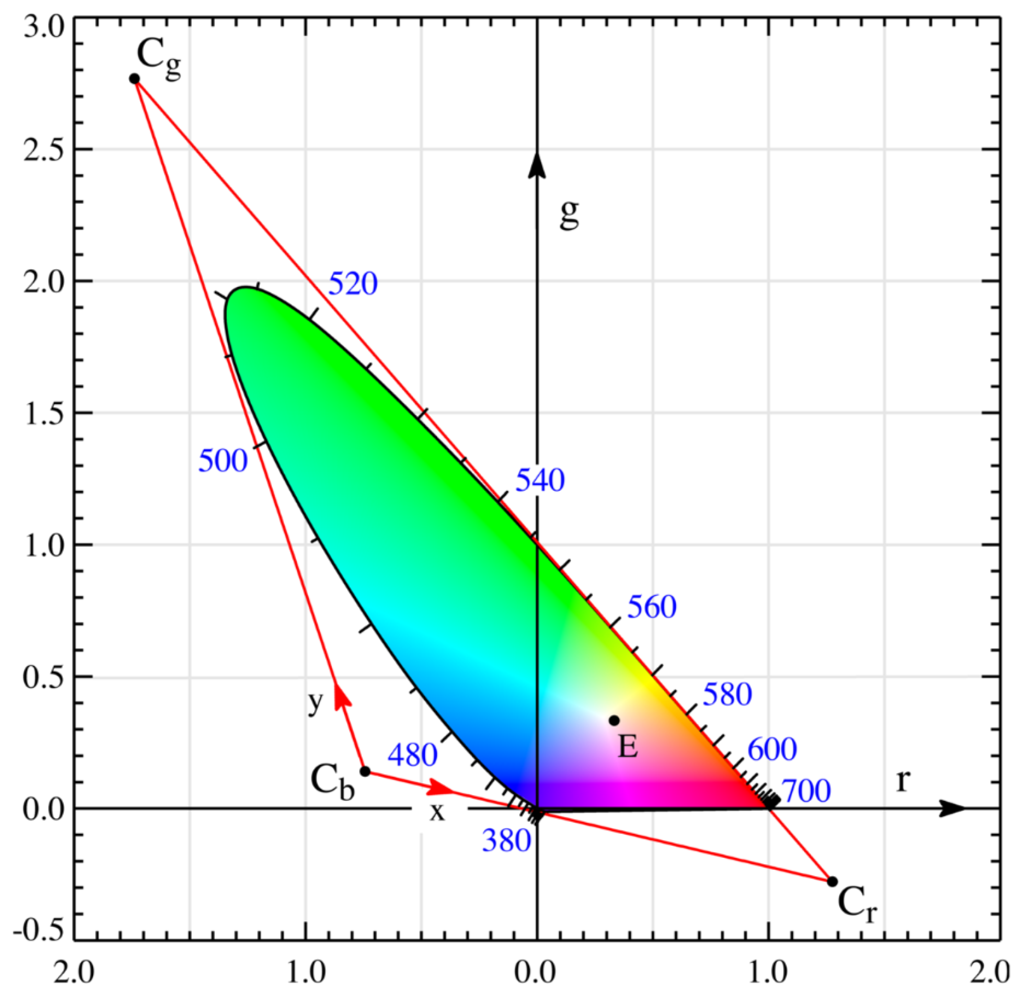
The CIE-xy color system [1,4,5,8] was created by the International Commission on Illumination (CIE) in 1931; see Figure 5. The intensity was separated from chromaticity using linear transformations and color mixing is simple.
To remove the intensity component, the RGB values are projected onto a unitary plane using Equation (14). This projection ensures that the sum of the RGB values is equal to 1, effectively normalizing the color values.
In this projection, the chromaticity of a color is represented by the values r and g in the r g plane. These values together convey information about both the color’s saturation and its corresponding wavelength.
r = R R + G + B , g = R R + G + B , b = 1 r g
After projecting to the unitary plane, colors form the area in Figure 5 (pseudo-coloring was used). Colors in the r < 0 are not captured within the RGB system.
The rainbow curve in this context is marked by color wavelengths with 100% color saturation. This means that each point on the curve corresponds to a specific wavelength and exhibits maximum color saturation [48].
Figure 6 illustrates the colors available within the RGB color system. The point E represents the position of equal energy white light, which corresponds to the chromaticity coordinates ( 1 / 3 , 1 / 3 ) . The line G–E is given as:
p G E = x G x E = i j k 0 1 1 1 3 1 3 1 = [ 2 3 , 1 3 : 1 3 ] T p G E : 2 3 x + 1 3 y 1 3 = 0 2 x + y 1 = 0
where x E = [ 1 / 3 , 1 / 3 : 1 ] T is the equal energy point position, [ 0 , 1 : 1 ] T is the green color position, and ≜ means projective equivalency. Details on projective geometric algebra use can be found in [16,32,49] and intersection computation in [50].
It is important to note that the positions discussed in the context of chromaticity are given in homogeneous coordinates. In this projective space representation, a point ( X , Y ) in Euclidean space can be expressed as [ w X , w Y : w ] T in projective space, where w is a non-zero scale factor. For the purposes of this discussion, w = 1 is used.
In the diagram Figure 5, the position x G = [ 0 , 1 : 1 ] T represents the pure green color. Similarly, x E = [ 1 / 3 , 1 / 3 : 1 ] T represents the equal energy white light position.
The function F ( x , y ) G E serves as a separation function, and it has a positive value for colors in the red (R)–white (E)–green (G) sector of colors. This means that given a point ( x , y ) in the chromaticity space, if F ( x , y ) G E 0 , the color falls within the red–white–green sector. On the other hand, if F ( x , y ) G E < 0 , the color falls within the green–white–blue sector. This function helps in determining which sector the given color belongs to. The specific equation for F ( x , y ) G E is F ( x , y ) G E = 2 x + y 1 .
The lines R–E and B–E are given similarly as:
p R E = x R x E = i j k 1 0 1 1 3 1 3 1 = [ 1 3 , 2 3 : 1 3 ] T p R E : 1 3 x 2 3 y + 1 3 = 0 x + 2 y 1 = 0
p B E = x B x E = i j k 0 0 1 1 3 1 3 1 = [ 1 3 , 1 3 : 0 ] T p B E : 1 3 x + 1 3 y = 0 x y = 0
where x R = [ 1 , 0 : 1 ] T , x B = [ 0 , 0 : 1 ] T and x E = [ 1 / 3 , 1 / 3 : 1 ] T are positions in homogeneous coordinates of the red, blue, and white colors in Figure 5. The colon “:” [ x , y : w ] T is used intentionally to emphasize that ( x , y ) is a position, while w is the homogeneous coordinate in the projective representation.
If the given color C falls within the B E R color sector (the green–white–blue sector), it is not a spectral color, meaning it does not correspond to a specific wavelength in the rainbow. In such cases, to determine the relevant wavelength, the complementary wavelength is used. For light, only the sectors R E G (red–white–green) and G E B (green–white–blue) are considered valid.
The separation function F ( x , y ) G E is used to decide which sector the color belongs to. If F ( x , y ) G E 0 , it indicates that the color is in the R E G sector, and if F ( x , y ) G E < 0 , it is in the G E B sector.
The separation function helps in determining the relevant sector for the given color as follows:
F ( x , y ) G E 0 the sector REG is to be used < 0 the sector GEB is to be used
Once the sector is identified, the edges of these sectors need to be labeled with the relevant wavelength λ to complete the process of computing the wavelength of the given color.

4. Wavelength Computation from RGB

In the case of the sector R E G (red–white–green), to determine the wavelength of the color represented by RGB, we find the intersection point D of a ray p E C that passes from point E (the equal energy white light position) through the point representing the color C with the edge of the relevant color sector, i.e., the line p R G .
The intersection point x D is computed as follows:
p E C = x E x C , p R G = [ 1 , 1 : 1 ] T x D = p R G p E C = [ x D , y D : w D ] T x D w D , y D w D
The lines representing the edges of the triangle, i.e., p R G = [ 1 , 1 : 1 ] T , p G B = [ 1 , 0 : 0 ] T , and p B R = [ 0 , 1 : 0 ] T , are constant.
Similarly, in the case of the sector G E B (green–white–blue), we find the intersection point x D as follows:
p E B = x E x B , p G B = [ 1 , 0 : 0 ] T x D = p G B p E C = [ x D , y D : w D ] T x D w D , y D w D
After computing the intersection point x D , the relevant wavelength λ for the color represented by RGB in the sector R E G or G E B can be determined.
In the actual implementation, the RGB values of the spectrum given in Table A1 need to be recomputed, and the relevant wavelengths on p R G and p G B are obtained. For the R E G sector, a projection to the x-axis is made, while for the G E B sector, a projection to the y-axis is made.
The algorithm is formed by the following steps:
  • Recompute the RGB values for the spectral curve using a resampling factor ξ ;
  • Compute the rainbow curve samples with 100% color saturation;
  • Uniformly resample the rainbow curve with a fine resolution using the scaling factor ξ to obtain RGB values for each point;
  • Obtain relevant wavelengths on p R G and p G B ;
  • Project the rainbow curve points to p R G (for the R E G sector) and p G B (for the G E B sector) lines to find the relevant points on the x-axis and y-axis, respectively;
  • Interpolate the wavelengths corresponding to these relevant points from the resampled RGB values obtained in step 1.
For a given pixel with a color C = ( r , g ) :
  • Compute the relevant position of the point D using the projection on either p R G or p G B , depending on whether C is in the R E G or G E B sector;
  • Use the r or g value of the point D as an index to the table with the interpolated wavelengths, applying the scaling factor ξ and the offset k as follows:
    i n d e x = ξ r , for REG sector i n d e x = ξ g + k , for GEB sector
  • Compute the relevant position of the point D using the projection on either p R G or p G B , depending on whether C is in the R E G or G E B sector.
The scaling factor ξ should represent the number of sub-intervals on the x- or y-axis, and k = ξ + 1 represents the index of the first row in the table with interpolated wavelengths for the y-axis.
Following these steps, the relevant wavelength λ is determined for any color C = ( r , g ) represented by RGB within the R E G or G E B sector.
It should be noted that there are actually two saturations:
  • saturation S R G B within the RGB cube, i.e., 100% means that the color of a pixel is on the face of the RGB cube;
  • saturation S C I E within the natural variety of colors, i.e., covering also colors outside of the RGB cube.
S R G B was used in the experiments presented.

5. Experimental Results

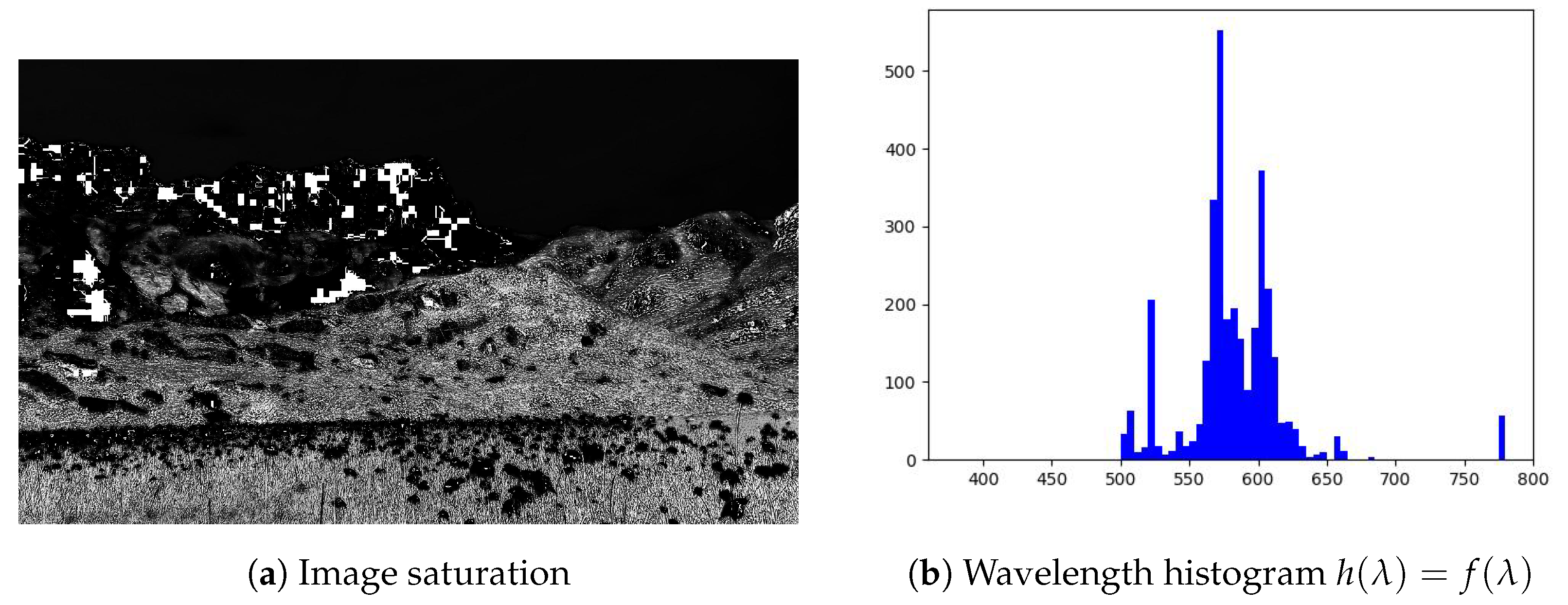
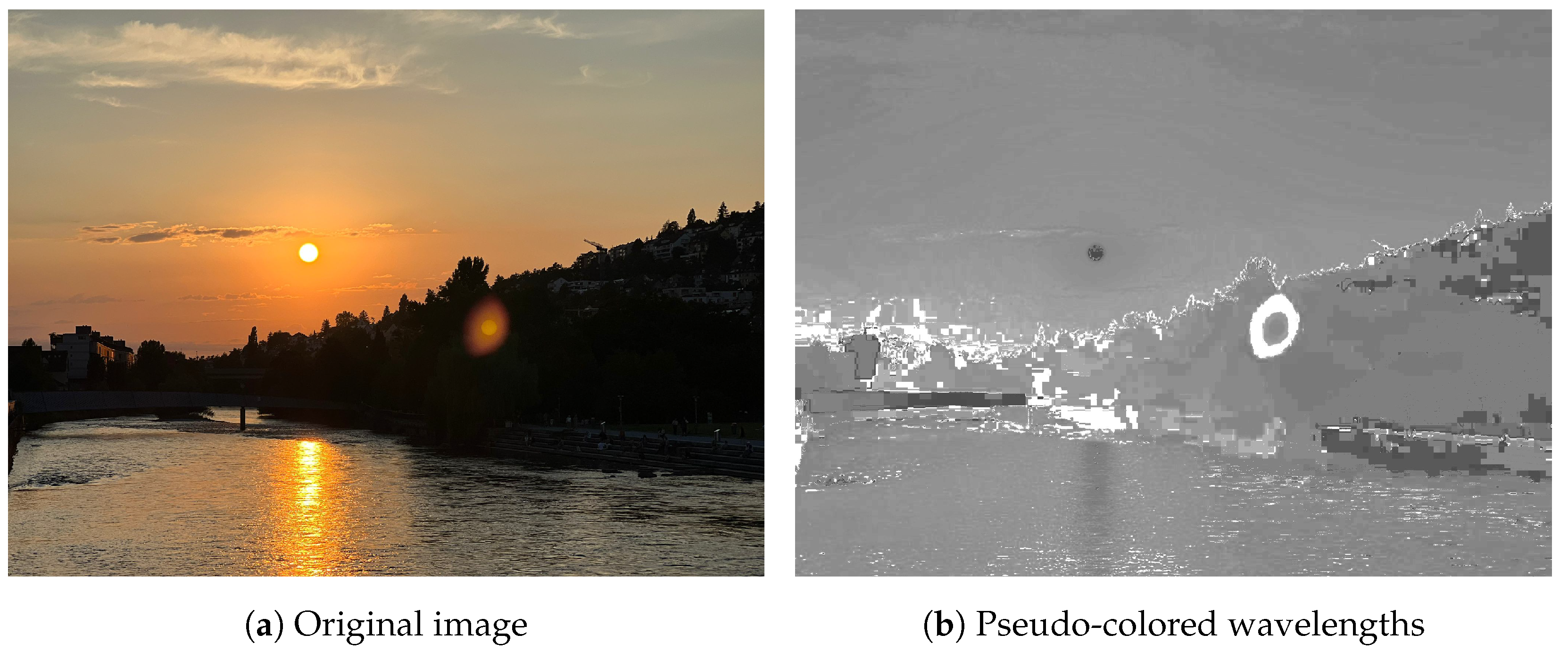
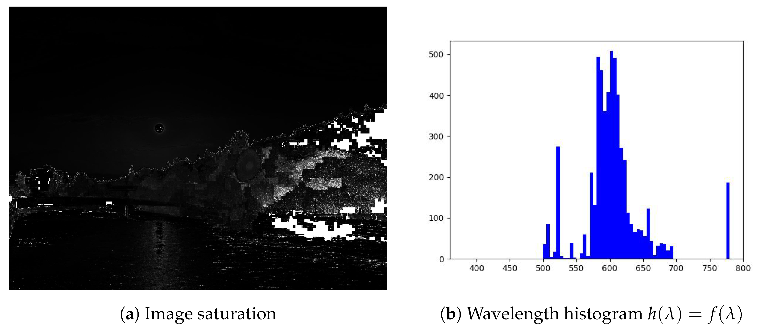
Examples of wavelength extraction for two different image types are presented in Figure 7, Figure 8, Figure 9 and Figure 10 with the wavelength histograms and the saturation level. The first is the Alps countryside scenery, and the second is a sunset. In both cases, the image resolution is 2048 × 1536 pixels, stored in the JPG format.
There is an unexpected occurrence of red colors with λ [770–780] nm (with a low saturation) in the histograms in Figure 8b and Figure 10b, which should be analyzed more deeply. However, the wavelength resolution in the interval λ [750–780] nm is low; see Figure 2 and Figure 5.

6. Conclusions

The presented method for RGB conversion to wavelength seems promising and has several advantages to be mentioned:
  • Look-up table generation: The use of a precomputed look-up table for wavelength conversion allows for fast and efficient processing of RGB images. Once the table is generated, it can be used for all images without the need for repeated calculations.
  • Simple run-time: The actual wavelength extraction using the look-up table involves simple linear interpolation, which is computationally efficient and convenient for processing large images.
  • Wide range of applications: The method opens up various applications in image processing, computer vision, and astro-image processing. Using wavelength information instead of traditional gray-scale or RGB values can provide valuable insights and may lead to novel image analysis techniques.
  • Potential for future exploration: The potential use of the XYZ color system, which eliminates negative values, can be an interesting direction for future research and development. Exploring other color spaces and their implications on image processing and analysis could yield valuable results.
Using wavelength information instead of traditional RGB or gray-scale values can offer additional spectral information that is not present in the standard color representations. This can be particularly useful in applications such as identifying specific materials or objects based on their spectral signatures, analyzing astronomical data, or studying the interaction of light with various materials.
There is a hope that the presented approach contributes to the field of image processing, and will be further explored and applied in various domains in the future. However, as with any new technique, thorough testing, evaluation, and comparison with existing methods will be important to establish its effectiveness and applicability in different scenarios.

Funding

This research received no external funding.

Data Availability Statement

Data available on request due to restrictions.

Acknowledgments

The author thanks recent students at the University of West Bohemia (UWB) for their comments and discussions. Special thanks belong to Lexova, L. (UWB), Bellot, T.C.L., and Berault, X. (University of Technology of Troyes, France—Erasmus students at UWB) for counter-implementations. Thanks belong also to the anonymous reviewers, as their comments and hints helped to improve this contribution significantly.

Conflicts of Interest

The authors declare no conflict of interest.

Appendix A. RGB Trichromatic Coefficients

To avoid numerical instability in Equation (14) the value of r in Table A1 was set for λ = 780 [nm] as r = 0.00001 .
Table A1. RGB spectral trichromatic values.
λ rgb   λ rgb
3800.00003−0.000010.001175800.245260.13610−0.00108
3850.00005−0.000020.001895850.279890.11686−0.00093
3900.00010−0.000040.003595900.309280.09754−0.00079
3950.00017−0.000070.006475950.331840.07909−0.00063
4000.00030−0.000140.012146000.344290.06246−0.00049
4050.00047−0.000220.019696050.347560.04776−0.00038
4100.00084−0.000140.037076100.339710.03557−0.00030
4150.00139−0.000700.066376150.322650.02583−0.00022
4200.00211−0.001100.115416200.297080.01828−0.00015
4250.00266−0.001430.185756250.263480.01253−0.00011
4300.00218−0.001190.247696300.226770.00833−0.00008
4350.00036−0.000210.290126350.192330.00537−0.00005
440−0.002610.001490.312286400.159680.00334−0.00003
445−0.006730.003790.318606450.129050.00199−0.00002
450−0.012130.006780.316706500.101670.00116−0.00001
455−0.018740.010460.311666550.078570.00066−0.00001
460−0.026080.014850.298216600.059320.000370.00000
465−0.033240.019770.272956650.043660.000210.00000
470−0.039330.025380.229916700.031490.000110.00000
475−0.044710.031830.185926750.022940.000060.00000
480−0.049390.039140.144946800.016870.000030.00000
485−0.053640.047130.109686850.011870.000010.00000
490−0.058140.056890.082576900.008190.000000.00000
495−0.064140.069480.062466950.005720.000000.00000
500−0.071730.085360.047767000.004100.000000.00000
505−0.081200.105930.036887050.002910.000000.00000
510−0.089010.128600.026987100.002100.000000.00000
515−0.093560.152620.018427150.001480.000000.00000
520−0.092640.174680.012217200.001050.000000.00000
525−0.084730.191130.008307250.000740.000000.00000
530−0.071010.203170.005497300.000520.000000.00000
535−0.053160.210830.003207350.000360.000000.00000
540−0.031520.214660.001467400.000250.000000.00000
545−0.006130.214870.000237450.000170.000000.00000
5500.022790.21178−0.000587500.000120.000000.00000
5550.055140.20588−0.001057550.000080.000000.00000
5600.090600.19702−0.001307600.000060.000000.00000
5650.128400.18522−0.001387650.000040.000000.00000
5700.167680.17087−0.001357700.000030.000000.00000
5750.207150.15429−0.001237750.000010.000000.00000
5800.245260.13610−0.001087800.000000.000000.00000

References

  1. Gonzalez, R.C.; Woods, R.E. Digital Image Processing, 3rd ed.; Prentice-Hall, Inc.: Upper Saddle River, NJ, USA, 2006. [Google Scholar]
  2. Faugeras, O.; Luong, Q.T.; Papadopoulou, T. The Geometry of Multiple Images: The Laws That Govern The Formation of Images of a Scene and Some of Their Applications; MIT Press: Cambridge, MA, USA, 2001. [Google Scholar]
  3. Starck, J.L.; Murtagh, F.; Bijaoui, A. Image Processing and Data Analysis: The Multiscale Approach; Cambridge University Press: Cambridge, UK, 1998. [Google Scholar]
  4. Szeliski, R. Computer Vision: Algorithms and Applications, 1st ed.; Springer: Berlin/Heidelberg, Germany, 2010. [Google Scholar]
  5. Burger, W.; Burge, M.J. Digital Image Processing: An Algorithmic Introduction Using Java, 2nd ed.; Springer Publishing Company: New York, NY, USA, 2016. [Google Scholar]
  6. Wang, M.; Lai, C.H. A Concise Introduction to Image Processing Using C++, 1st ed.; Chapman & Hall/CRC: London, UK, 2008. [Google Scholar]
  7. Nassau, K. (Ed.) Color for Science, Art and Technology, 1st ed.; North Holland: Amsterdam, The Netherlands, 1998; p. 490. [Google Scholar]
  8. Hall, R. Illumination and Color in Computer Generated Imagery; Springer: Berlin/Heidelberg, Germany, 1988. [Google Scholar]
  9. Jackson, R.; MacDonald, L.; Freeman, K. Computer Generated Color: A Practical Guide to Presentation and Display; John Wiley & Sons, Inc.: Hoboken, NJ, USA, 1994. [Google Scholar]
  10. Stone, M. Field Guide to Digital Color; A. K. Peters, Ltd.: Natick, MA, USA, 2002. [Google Scholar]
  11. Giorgianni, E.J.; Madden, T.E. Digital Color Management: Encoding Solutions; Addison-Wesley Longman Publishing Co., Inc.: Boston, MA, USA, 1998. [Google Scholar]
  12. Hoffmann, M. Digital signal processing mathematics. CAS—CERN Accel. Sch. Course Digit. Signal Process. 2008. [Google Scholar]
  13. Hrdina, J.; Vašík, P.; Matoušek, R.; Návrat, A. Geometric algebras for uniform colour spaces. Math. Methods Appl. Sci. 2018, 41, 4117–4130. [Google Scholar] [CrossRef]
  14. Ohta, N.; Robertson, A.R. Colorimetry: Fundamentals and Applications; Wiley: Hoboken, NJ, USA, 2006; pp. 1–334. [Google Scholar] [CrossRef]
  15. Hornak, P. Svetelna Technika (Lighting Technology); Alfa: Bratislava, Slovakia, 1989; p. 247. [Google Scholar]
  16. Skala, V. Length, Area and Volume Computation in Homogeneous coordinates. Int. J. Image Graph. 2006, 6, 625–639. [Google Scholar] [CrossRef]
  17. Keller, P.A. Electronic Display Measurement: Concepts, Techniques, and Instrumentation; John Wiley&Sons: London, UK, 1997; p. 325. [Google Scholar]
  18. Zhou, W.; Zhang, X.; Wang, H.; Gao, S.; Lou, X. Raw Bayer Pattern Image Synthesis for Computer Vision-oriented Image Signal Processing Pipeline Design. arXiv 2021, arXiv:2110.12823. Available online: https://arxiv.org/pdf/2110.12823.pdf (accessed on 12 September 2023).
  19. Park, J.; Chong, J. Pattern Transformation Method for Digital Camera with Bayer-Like White-RGB Color Filter Array. IEICE Trans. Inf. Syst. 2015, E98.D, 2021–2025. [Google Scholar] [CrossRef]
  20. Poomrittigul, S.; Ogawa, M.; Iwahashi, M.; Kiya, H. Reversible color transform for Bayer color filter array images. APSIPA Trans. Signal Inf. Process. 2013, 2, e5. [Google Scholar] [CrossRef]
  21. Mohammed, S.K.; Rahman, K.M.M.; Wahid, K.A. Lossless Compression in Bayer Color Filter Array for Capsule Endoscopy. IEEE Access 2017, 5, 13823–13834. [Google Scholar] [CrossRef]
  22. Li, D.; Wang, M.; Jiang, J. China’s high-resolution optical remote sensing satellites and their mapping applications. Geo-Spat. Inf. Sci. 2021, 24, 85–94. [Google Scholar] [CrossRef]
  23. Zhong, Y.; Wang, X.; Wang, S.; Zhang, L. Advances in spaceborne hyperspectral remote sensing in China. Geo-Spat. Inf. Sci. 2021, 24, 95–120. [Google Scholar] [CrossRef]
  24. Zhao, B.; Gao, L.; Liao, W.; Zhang, B. A new kernel method for hyperspectral image feature extraction. Geo-Spat. Inf. Sci. 2017, 20, 309–318. [Google Scholar] [CrossRef]
  25. Roy, P. Spectral reflectance characteristics of vegetation and their use in estimating productive potential. Proc. Plant Sci. 1989, 99, 59–81. [Google Scholar] [CrossRef]
  26. Gates, D.M.; Keegan, H.J.; Schleter, J.C.; Weidner, V.R. Spectral properties of plants. Appl. Opt. 1965, 4, 11–20. [Google Scholar] [CrossRef]
  27. Ouzounis, T.; Rosenqvist, E.; Ottosen, C.O. Spectral Effects of Artificial Light on Plant Physiology and Secondary Metabolism: A Review. HortSci. Horts 2015, 50, 1128–1135. [Google Scholar] [CrossRef]
  28. Carranza-García, M.; Galán-Sales, F.J.; Luna-Romera, J.M.; Riquelme, J.C. Object detection using depth completion and camera-LiDAR fusion for autonomous driving. Integr. Comput. Aided Eng. 2022, 29, 241–258. [Google Scholar] [CrossRef]
  29. Chakraborty, D.; Singh, S.; Dutta, D. Segmentation and classification of high spatial resolution images based on Hölder exponents and variance. Geo-Spat. Inf. Sci. 2017, 20, 39–45. [Google Scholar] [CrossRef]
  30. Verma, G.; Kumar, M. Under-water image enhancement algorithms: A review. In Proceedings of the AIP Conference Proceedings, Mathura, India, 24–26 December 2023; Volume 2721, p. 040031. [Google Scholar] [CrossRef]
  31. Vince, J. Geometric Algebra: An Algebraic System for Computer Games and Animation, 1st ed.; Springer Publishing Company: New York, NY, USA, 2009. [Google Scholar]
  32. Skala, V. Intersection Computation in Projective Space using Homogeneous Coordinates. Int. J. Image Graph. 2008, 8, 615–628. [Google Scholar] [CrossRef]
  33. Lengyel, E. Mathematics for 3D Game Programming and Computer Graphics, 3rd ed.; Course Technology Press: Boston, MA, USA, 2011. [Google Scholar]
  34. Skala, V.; Karim, S.; Kadir, E. Scientific Computing and Computer Graphics with GPU: Application of Projective Geometry and Principle of Duality. Int. J. Math. Comput. Sci. 2020, 15, 769–777. [Google Scholar]
  35. Johnson, M. Proof by Duality: Or the Discovery of “New” Theorems. Math. Today 1996, 138–153. [Google Scholar]
  36. Skala, V.; Kuchař, M. The hash function and the principle of duality. In Proceedings of the Computer Graphics International Conference, CGI, Hong Kong, China, 6 July 2001; pp. 167–174. [Google Scholar]
  37. Arokiasamy, A. Homogeneous coordinates and the principle of duality in two dimensional clipping. Comput. Graph. 1989, 13, 99–100. [Google Scholar] [CrossRef]
  38. Skala, V. Duality, barycentric coordinates and intersection computation in projective space with GPU support. WSEAS Trans. Math. 2010, 9, 407–416. [Google Scholar]
  39. Skala, V. Projective geometry, duality and Plücker coordinates for geometric computations with determinants on GPUs. In Proceedings of the International Conference of Numerical Analysis and Applied Mathematics (ICNAAM 2016), Rhodes, Greece, 19–25 September 2017; Volume 1863. [Google Scholar] [CrossRef]
  40. Skala, V. Geometric Transformations and Duality for Virtual Reality and Haptic Systems. Commun. Comput. Inf. Sci. 2014, 434 Pt I, 642–647. [Google Scholar] [CrossRef]
  41. Skala, V. Duality and intersection computation in projective space with GPU support. In Proceedings of the International Conference on Applied Mathematics, Simulation, Modelling, Corfu Island, Greece, 22–25 July 2010; pp. 66–71. [Google Scholar]
  42. Skala, V. Geometry, duality and robust computation in engineering. WSEAS Trans. Comput. 2012, 11, 275–293. [Google Scholar]
  43. Zapletal, J.; Vaněček, P.; Skala, V. RBF-based image restoration utilising auxiliary points. In Proceedings of the Computer Graphics International Conference, CGI, Victoria, BC, Canada, 26–29 May 2009; pp. 39–43. [Google Scholar] [CrossRef]
  44. Uhlir, K.; Skala, V. Radial basis function use for the Restoration of damaged images. In Computer Vision and Graphics (ICCVG 2004), Computational Imaging and Vision; Springer: Dordrecht, The Netherlands, 2006; Volume 32, pp. 839–844. [Google Scholar] [CrossRef]
  45. Hassan, M.F.; Adam, T.; Rajagopal, H.; Paramesran, R. A hue preserving uniform illumination image enhancement via triangle similarity criterion in HSI color space. Vis. Comput. 2022. [Google Scholar] [CrossRef]
  46. Plataniotis, K.N.; Venetsanopoulos, A.N. Color Image Processing and Applications; Springer: Berlin, Germany, 2010; p. 355. [Google Scholar] [CrossRef]
  47. Ma, S.; Ma, H.; Xu, Y.; Li, S.; Lv, C.; Zhu, M. A low-light sensor image enhancement algorithm based on HSI color model. Sensors 2018, 18, 3583. [Google Scholar] [CrossRef]
  48. Skala, V.; Bellot, T.C.L.; Berault, X. Wavelength Computation from RGB. Lect. Notes Comput. Sci. 2023, 13957 LNCS, 423–430. [Google Scholar] [CrossRef]
  49. Skala, V. Barycentric coordinates computation in homogeneous coordinates. Comput. Graph. 2008, 32, 120–127. [Google Scholar] [CrossRef]
  50. Skala, V. A Brief Survey of Clipping and Intersection Algorithms with a List of References. Informatica 2023, 34, 169–198. [Google Scholar] [CrossRef]
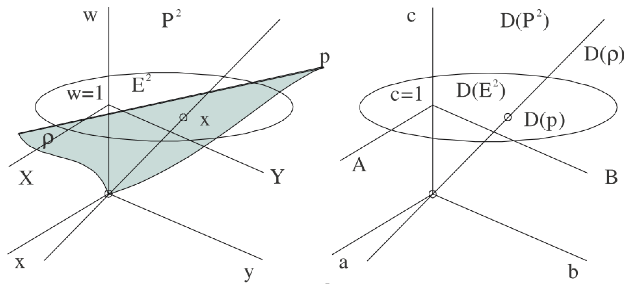
Figure 1. Projective extension and dual space.
Computers 12 00182 g001
Figure 2. RGB coefficients; courtesy of Marco Polo.
Computers 12 00182 g002
Figure 3. Diagram of intensity (Y) and chromatic coordinates IQ.
Computers 12 00182 g003
Figure 4. Diagram of chromatic coordinates IQ for different wavelengths λ .
Computers 12 00182 g004
Figure 5. Colors in RGB and XYZ coordinate systems.
Computers 12 00182 g005
Figure 6. RGB color sectors.
Computers 12 00182 g006
Figure 7. Original image and wavelengths.
Computers 12 00182 g007
Figure 8. Image color saturation and wavelength histogram.
Computers 12 00182 g008
Figure 9. Original image and wavelengths.
Computers 12 00182 g009
Figure 10. Image color saturation and wavelength histogram.
Computers 12 00182 g010
Disclaimer/Publisher’s Note: The statements, opinions and data contained in all publications are solely those of the individual author(s) and contributor(s) and not of MDPI and/or the editor(s). MDPI and/or the editor(s) disclaim responsibility for any injury to people or property resulting from any ideas, methods, instructions or products referred to in the content.