Project Report

Development of a Self-diagnostic System Integrated into a Cyber-Physical System

by
Domingos F. Oliveira
1,2,*,
João P. Gomes
3,
Ricardo B. Pereira
4,
Miguel A. Brito
2,* and
Ricardo J. Machado
2
1
Department of Informatics and Computing, University Mandume Ya Ndemufayo, Lubango 3FJP+27X, Angola
2
Centro Algoritmi, Department of Information Systems, University of Minho, 4800-058 Guimarães, Portugal
3
Department of Information Systems, University of Minho, 4804-533 Guimarães, Portugal
4
Department of Informatics, University of Minho, 4710-057 Braga, Portugal
*
Authors to whom correspondence should be addressed.
Computers 2022, 11(9), 131; https://doi.org/10.3390/computers11090131
Submission received: 22 July 2022 / Revised: 25 August 2022 / Accepted: 25 August 2022 / Published: 29 August 2022
(This article belongs to the Special Issue Computational Science and Its Applications 2022)

Abstract

:
CONTROLAR provides Bosch with an intelligent functional testing machine used to test the correct functioning of the car radios produced. During this process, the radios are submitted to several tests, raising the problem of how the machine detects errors in several radios consecutively, making it impossible to know if the device has a problem since it has no module to see if it works correctly. This article arises from the need to find a solution to solve this problem, which was to develop a self-diagnostic system that will ensure the reliability and integrity of the cyber-physical system, passing a detailed state of the art. The development of this system was based on the design of an architecture that combines the KDT methodology with a DSL to manage and configure the tests to integrate the self-diagnostic test system into a CPS. A total of 28 test cases were performed to cover all its functionalities. The results show that all test cases passed. Therefore, the system meets all the proposed objectives.

1. Introduction

The production of many industrial organisations is supported by cyber-physical systems (CPS), which are the integration of computing, networking and physical processes, and which must therefore achieve maximum performance in production, as the use of CPS is necessary for the success of production within an organisation.
A CPS integrates the dynamics of the physical processes with the software and the network, providing abstractions, modelling techniques, design and analysis for the integrated whole. These systems must remain reliable and guarantee their functionality [1]. However, to ensure that these systems function correctly, a regular diagnosis of them is required. CPS tests require highly qualified engineers to design them since their computational part is programmed in low-level languages [2,3]. Traditional test systems are tailored to each case, requiring a very costly and time-consuming effort to develop, maintain or reconfigure. The current challenge is to develop innovative and reconfigurable architectures for testing systems using emerging technologies and paradigms that can provide the answer to these requirements [4]. The challenge is to automate the maximum number of tasks in this process and get the most out of the test system, be it a CPS or just software.
CONTROLAR is a company dedicated to developing hardware and software for the industry, with a tremendous vocation in the automobile electrical components industry and excellent know-how in developing industrial automation and functional and quality test systems for electronic devices. One of its business areas is system testing, which is based on the development and integration of available test systems, monitoring data for the validation of electrical characteristics and quality tests, and using data collection boards, generators, and specific equipment for signal and data acquisition and analysis.
For this purpose, a partnership was developed from the Consortium’s union of skills and knowledge between CONTROLAR, the University of Minho [5,6], the Computer Graphics Centre [7], and the research project called Test System Intelligent Machines (TSIM). This project aims to ensure value creation in CONTROLAR’s products (as a current supplier of Bosch) and its adaptation to the reality of Bosch Industry 4.0. Furthermore, the aim is to develop tools that make CONTROLAR’s automatic test equipment more flexible, efficient and intelligent.
One of the products CONTROLAR supplies to Bosch today is the Intelligent Functional Test Machine [8]. This machine is a CPS developed to perform different functional tests on electronic devices and components. Bosch uses this machine at the end of the production line to ensure the correct functionality of the car radios.

1.1. Problem Definition

As stated above, one of the products CONTROLAR supplies to Bosch is the Intelligent Functional Testing Machine [8], a CPS developed to perform different levels of functional tests on electronic devices and components. Bosch uses this machine at the end of the production line to ensure the correct functionality of the car radios. Therefore, the car radios are subjected to various tests while using this machine.
The problem appears when the machine detects errors in several radios, indicating that the production line had failed in one of its segments, causing possible errors in all radios of that line. Thus, a scenario in which all car radios come with errors means that something has failed in production. This is unacceptable for the company since it will cause unexpected delays. Moreover, it becomes necessary to repair all the car radios, which brings with it an increase in costs. When this happens, the organisation tends to attribute the problem to the machine and not to its products, leading to attempts to discover the problem with the machine.
Another problem is that the machine has no module to understand whether it is working correctly or not. The only way to know is by changing the machine construction’s physical connections and internal properties to try to understand the malfunction. Most of the time, this happens because they try to look for errors in the machine and usually always end up causing damage to it without realising it because they do not know all the details of its construction and start changing many until they make the machine wholly unusable and without finding the problem. The likely result of these actions is the need to repair the machine or even replace it, which causes financial losses.

1.2. Motivation and Objectives

This work arises from the need to find a solution to solve the stated problem. It is also an innovative solution with contributions to the world of research in CPS and self-diagnosis tests systems. The answer is to integrate a self-diagnosis system in the machine that can test the device’s functionality. When these car radio failures appear, Bosch can be sure if the problem is really on the machine or in the production line of the car radios. As the device is a CPS, it allows the integration of a software system that can control and manage all of its actions. Therefore, it is necessary to develop a testing system to order the tests and their execution, detecting internal machine failures. However, before we can create a plan, it is essential to find the correct architecture for a testing system. This architecture should be as suitable as possible to the problem we are facing and as generic as possible regarding what a testing system is.
Developing a self-diagnostic system for integration into a CPS capable of performing CPS self-diagnostics in real-time, thus ensuring its integrity, is the main objective of the paper. As specific objectives, regarding the analysis and specifications of the system, we develop and propose a new architecture for test management and configuration as well as a new architecture for the self-diagnostic test system, offer an architecture to integrate the self-diagnostic test system into a CPS, develop a self-diagnostic test system and validate the self-diagnostic test system.
Regarding integration of the self-diagnosis tests system with the CPS, the work/research methodology should go through the study of the problem, a survey of state of the art, reflection on the technologies to be used in the development, development of the system architecture and finally, the development, validation and integration of the system.

1.3. Contribution

The contribution of the work involves finding a solution to the problem presented, an innovative solution with donations to the current state of the art, on a modular and extensible architecture for self-diagnostic testing systems that combines the keyword-driven testing methodology with a domain-specific language to manage and configure the system tests. This is essential because this architecture can be applied to any self-diagnostic testing system without restricting any type of test, physical or logical, and can also be extended to the CPS. We also contribute an architecture to develop and integrate the self-diagnostic testing system into a CPS. This contribution is vital because it proves the modularity of the self-diagnostic testing system architecture, demonstrating how we can extend it into a CPS and finally a self-diagnostic test system ready to be integrated into a CPS. This contribution allows us to validate the proposed architectures and the usefulness of the developed method in the self-diagnosis of CONTROLAR machines.

1.4. Document Structure

The paper’s first sections aim to look at state of the art in CPS and self-diagnostic systems to understand if there are already strategies or architectures for these two systems to be brought together. It also examines the state of the art in test automation and KDT methodology and analyses and compares some current tools that use this testing methodology. The third section analyzes and specifies the requirements and structure of the system and defines the technologies used for its implementation. The fourth section explains the architecture defined for the design. This process was divided into three stages, starting with the definition of an architecture for the management and configuration of the system tests, which will then be integrated into the architecture of the self-testing system. Finally, the CPS architecture is composed, integrating all its components and the two architectures previously defined. The fifth section describes the system’s implementation, explains each of the elements involved, and presents a validation of the procedure performed through several of the test cases executed. Finally, the last section contains the project’s conclusions, summarising all the work done and presenting future work.

2. State of the Art

This section reviews the state of the art in CPS, test automation, the keyword-driven testing (KDT) framework, and a brief introduction to the concept of domain-specific language (DSL) and, more specifically, how to apply this concept with another tool for language recognition (ANTLR) is given.

2.1. Cyber-Physical Systems

CPS are integrations of computing, network, and physical processes, integrating the dynamics of physical processes with software and the web, providing abstractions and modelling, design, and analysis techniques for the integrated whole. However, to realize their full potential, the main conceptions of computing need to be rethought and improved [1].
Currently, CPS requires solutions that support it at the device, system, infrastructure, and application level. This is a challenge that includes an engineering approach and a fusion of communication, information and automation technologies [9]. For the effective orchestration of software and physical processes, semantic models are needed to reflect the relevant properties to both [1]. The current challenge is to develop innovative, agile, and reconfigurable architectures for control systems, using emerging technologies and paradigms that can provide the answer to requirements [4]. It is still necessary to maintain a balance between the needs and the notion of lightweight and safe solutions [10]. Software development for this area presents a challenge [11].
The communication infrastructure is essential for testing. Most focus on communications-oriented research, privacy and security of the infrastructure [12,13]. Tests must be designed to provide a remote interface [14]. Verification and composition testing methods must also be adapted to the CPS. Creating an automated or semi-automatic process to assess the results of system tests is a challenge in CPS testing [15]. There are still many limitations to the broader industrial application of CPS testing [16]. The challenge will be to automate the maximum number of tasks and get the most out of CPS.

2.2. Text Automation

Automating testing is critical to the quality of the final product. Thus, software developers are required to have a set of quality standards during all phases of project development because organizations, when adopting software, rely on quality criteria since one of the pillars in ensuring software quality is testing [17].
In the development market, the current concern is to create quality software, as the goal of a software tester is to define the implementation of this software that meets all specifications and expectations and the automation of testing while being aware of when and where testing should be performed, thus giving the team more time to plan to test. In addition, automation results in the mechanization of the entire process of monitoring and managing the testing and evaluation needs associated with software development [18].

2.3. Fault Detection

Fault detection is the examination of faults present in machinery components. A recent study found that most research on fault detection focuses on incipient faults so that the next stage of the FDD process can be performed [19].
The purpose of fault detection is the “detection of the occurrence of faults in the functional units of the process, which lead to undesired or intolerable behaviour of the whole system”. Most of the modern automated fault detection methods are model-based, be it first principle models, rule-based models (if-then rules), or machine-learning models based on several measured variables. Fault detection can also be carried out manually. In fact, conventional complaint-driven maintenance can be regarded as a form of manual fault detection-based maintenance, as complaints are derived from observed state X such as temperature or parameter Φ such as window operability from the occupants. Besides identifying abnormal operations, fault detection can provide valuable information for further fault diagnostics [20].

2.4. Keyword-Driven Testing

KDT is a type of automation testing methodology known as table testing or action-based testing that uses a table (spreadsheet) format to define keywords or action words that represent the content of the tests. KDT presents itself as a valuable test method to support testing requirements in industrial control software [16]. However, recent results from researchers have shown that the KDT test design is complex, with multiple levels of abstraction, and that this design favours reuse, which has the potential to reduce the changes required during evolution [21]. Furthermore, keywords change at a relatively low rate, indicating that only localised and refined changes are made after a keyword is created. However, the same results also showed that KDT techniques require tools to support keyword selection, refactoring, and test repair [22].

Current Tools

For the development of work, we used some test automation tools that implement the keyword-driven testing framework, such as Selenium [23], QuickTest Professional [24,25], TestComplete [26], SilkTest [27,28], Ranorex [29] and the Robot Framework [30].

2.5. Domain-Specific Language

DSL is a language intended for use in the context of a particular domain and is quite powerful for representing and addressing problems and solutions in that sphere [31]. Used to generate source code from a keyword, plus code generation from a DSL is not mandatory. Some researchers have used DSL in CPS and left their testimony on how the specification language hides the implementation details. Specifications are automatically enriched with performance through reusable mapping rules. These rules are implemented by developers and specify the order of execution of modules and how input/output variables are implemented [32]. This enables the reuse of software components and improves software productivity and quality [33].

ANTLR

ANTLR is a parser generator [34] because it takes a text and turns it into an organised structure, a tree, called an abstract syntax tree (AST) [35], which is like a story describing the content of the code (logical representation), created by joining the various parts [36]. Figure 1 shows this.
The Parsing process shown in Figure 1 goes through three phases: lexical analysis, syntactic analysis and transformations.
ANTLR is a parser generator that parses the input dynamically at runtime using a top-down left-to-right parser, building a leftmost derivation of the information and looking at any number of tokens in advance when selecting between alternative rules [37]. In addition, the Visitor pattern allows us to decide how to traverse the tree and which nodes we will visit, allowing us to define how many times we see a node [38].

2.6. REST

REST is an architectural style between web applications, facilitating communication between systems [39]. It is a protocol developed specifically to create web services, which aims to be platform- and language-independent, using the Hypertext Transfer Protocol (HTTP) for communication between servers. This protocol is based on six fundamental principles, namely a client-server architecture, statelessness, caches, a uniform interface, a layered system, and the code on demand [40,41].

2.7. Discussion

In general, this section approaches this paper’s state of the art, namely the current state of research development in CPS, and exposes the proven importance of test automation. Then, the concepts of the KDT framework are presented. DSL is also addressed, in addition to how ANTLR works internally. We also cover the REST protocol widely used in web services development.
This review revealed that, although there are several tools dedicated to the management and execution of tests, none of them are intended for self-diagnostic testing of CPS. Therefore, this work will aim to take advantage of the best features of self-testing systems to develop a strategy oriented to CPS self-diagnosis.

3. Analysis and Specification

The purpose of this section is to provide a detailed analysis of the requirements that the system must satisfy, which are also accompanied by the needs of CONTROLAR since the system will be developed for application in its CPS.

3.1. Requirements

Based on the objective of the work, which is to build a system that allows CPS self-diagnosis by performing tests on it, this system should therefore also be able to manage the tests performed and the results obtained. Based on this assumption, a set of system requirements are extracted, organised into general needs, specific requirements, and user categories and permissions.

3.2. System Structure

After elaborating on the system requirements, we present an overview of the system structure. In the requirement analysis, the solution chosen for the design of this system is a client-server architecture based on the REST model. The client-server model aims to divide tasks to reduce the system load. The server will offer a series of services to a specific user, an Application Programming Interface (API), and will perform the tasks requested by the user and return the data. On the other hand, the client is responsible for requesting a specific service from the server through messages.
The system will consist of the client and server, where the client will communicate with the server through HTTP requests, and the server will respond through HTTP responses. The server will be responsible for connecting to the database, making the transactions or queries and returning the results.

3.3. Technologies to Use

After analyzing the requirements and the structure of the system, this section describes the chosen technologies for the system development and implementation. The system can be divided into two main components, the client-side (frontend) and the server-side (backend).

3.3.1. Backend Technology

This system component will include the API server and the database used to ensure the consistency of the system data. Once it was decided that the system should be implemented as a web application, it made sense to use a platform that runs on the web and the JavaScript language Pluralsight2021JavaScript. For this, Node.js Foundation2021Node.js was chosen. Using Node.js will allow the application to be fast and scalable, and for this to happen, the platform relies on non-blocking I/O, asynchronous event-driven programming and a single thread.
For data consistency, the MongoDB database was chosen, which is a document database; it stores data in JavaScript Object Notation (JSON)-type documents. As the data will always be traded as JSON documents, the use of MongoDB will maintain this consistency in a more natural, expressive and powerful way than any other model [42]. It manages relationships between data, provides schema validation, and translates between objects in code and the representation of those objects in MongoDB. For example, in Figure 2, we can see this mapping of objects between Node.js and MongoDB through Mongoose.

3.3.2. Frontend Technology

For this system, the tool chosen was React.js [43] due to its ability to interact with applications developed with the technologies selected for Backend [44]. In React.js, it is easy to create an interactive UI because it projects simple visualizations for each application state and efficiently updates and renders the right components when their data changes [45]. Moreover, React.js allows the creation of encapsulated components that manage their condition. Through the composition of these components, it is possible to create more complex interfaces with less complexity in the code.
Since the component’s logic is written in JavaScript instead of models, we can easily pass data through the application and maintain the state outside the DOM [46]. Furthermore, the React virtual DOM allows the implementation of some intelligent alternative solutions that guarantee the quick rendering of the components, which is necessary since the data must be presented immediately and effectively. In these situations, React finds an ideal way to update the UI, and all one needs to do is provide the data flow through the API [47]. The React virtual DOM acts as an intermediate step whenever there are changes in the web page. It allows the renderings to be faster and more efficient, making the pages highly dynamic. We can see the difference between Real DOM and React Virtual DOM in Figure 3.

3.4. Discussion

The requirements for the development of the system are divided into three to facilitate better interpretation. First, a basic structure was defined, separating it into the API Server responsible for accessing the data and implementing the logic and the client, accountable for the user interface. We present and explain the technologies chosen for the development of the system. MongoDB, Express and Node.js were selected for the server side, and for the client side, React.js was chosen.

4. Architecture

For a better understanding, we present the general architecture of the CPS, which comprises several components. Its modelling was divided into three phases. In the first phase, the part of the architecture that concerns the management and configuration of the system tests is explained after the presentation of the general architecture of the CPS.

4.1. Test Management and Configuration Archicture

The architecture we propose in this section aims to automate and facilitate new tests. We use the KDT methodology in conjunction with a DSL in this architecture. To fully understand the architecture and how its components interconnect, it will be explained how KDT and DSL are applied and later how they are integrated into the same architecture.

4.1.1. Keyword-Driven Testing Methodology

KDT will be used to abstract low-level code scripts, associating each hand with a keyword that represents it as descriptively and explicitly as possible, making it easier for the user. We will also associate each keyword with metadata related to the corresponding test stored in a database. Figure 4 represents the approach taken in using KDT. The names given to the difficulties in the figure are only fictitious to show that the words given to the keywords should be as descriptive as possible.
In Figure 4, we see a stack of scripts that represent the primitive test in the system that focuses only on testing features, as long as they can be well-identified only by a word that can serve as a keyword. We also see the representation of a database that will store all the information and metadata about the tests existing in the system. Connected to the database and the stack of scripts, we see a table with keywords representing all the information related to a trial, which is the most relevant element in the figure because it is where we can tell all the data from the stack of scripts and the database. This is done with just one word that concedes testers with little programming knowledge to interpret what each test does or means. Finally, we have the link between the tester and the keywords table that demonstrates they will only have access to the keywords without knowing any implementation details.

4.1.2. Domain-Specific Language

Using KDT does not bring advantages since we need something to design a test execution flow. For this, we have DSL, facilitating a friendly language for testers without the need for programming knowledge. The proposed language is simple but allows for new scripts with new execution flows and logic rules applied. This is achieved only by using the keywords defined by KDT and some terminal symbols defined in DSL. Table 1 shows the designated DSL terminal signs and what they represent.

4.1.3. Proposed Architecture

A final abstraction of all these processes is necessary to achieve the full potential of the integration between KDT and DSL. Figure 5 presents the architecture that guarantees to abstract the entire complex process of creating new tests for the system, thus giving the possibility to users less endowed with programming knowledge to build new tests.
By the illustration of Figure 5, it becomes possible to verify two tables representing the keywords and symbols used to form new test scripts, presenting as ingredients keywords that correspond to the defined tests and are available in the system to be used in the creation of new tests.
It is still possible to verify by the same Figure 5, the link between the existing difficulties with the keywords table, since the elements of the table symbols present the terminal symbols of the defined in the DSL. This allows us to give an organization and logic to the new tests, and, in this way, by the available elements in the two tables, it becomes possible to write the new test script, which demonstrates the links between the component Write Script and the tables.
As soon as a new test script is written, the DSL will analyse it using a lexer and parser and verify that it is syntactically and lexically well written. This step is represented in the compile connection. If the script complies with the defined rules, the DSL will compile that script and generate the code for a new test. However, for that, it needs access to the principle of the tests used through the keywords, which is represented with the connection Get Tests. The DSL will generate the code for a new test at the end of this process. This is described in the Generate Code link. The new test is available for execution in the system from that moment.

4.2. Self-Diagnosis Test System Architecture

In this section, the architecture for the self-diagnosis tests system will be presented, divided into a frontend, backend and database.

Proposed Architecture

Here, we have represented the corresponding architecture of the junction of the frontend and the backend, which corresponds to the self-diagnostic testing system that will be integrated into a CPS, as shown in Figure 6.
In this architecture are represented the three main tiers of the system. The frontend tier, which communicates with the backend tier, is responsible for the system logic through HTTP requests and responses. The backend tier communicates with the database tier, which is responsible for the consistency of the system data, through appeals in the form of queries and answers in the form of JSON documents, all processed and validated through the object data modeling.
The most crucial point of this architecture, which distinguishes it from the rest, is the inclusion and integration of the test management and configuration architecture, which, along with the other components of the system, will allow the system to ensure its integrity and functionality through real-time self-diagnostic testing and also configure new tests for the system with much less complexity.

4.3. General Architecture for the Cyber-Physical System

The final CPS architecture is presented and explained, where we integrate all its components with the self-diagnosis tests system. This architecture aims to allow the CPS to obtain the ability to diagnose itself and, thus, be able to identify the failures in case of any internal error. The final architecture of the system can be seen in Figure 7 and is explained below.
In this architecture, we can quickly identify four groups of components. Three of them will form an integral part of the CPS: devices under test, electronic test drivers and the self-diagnosis test system. The last group, user types, will be an essential intervenient, but it is not an integral part of the CPS.
The devices under test group contains the devices that can be subjected to tests: the car radios and the machine itself. The elements car radio and TSIM machine represent the two types of devices.
The electronic test drivers group is responsible for the primitive tests of the system, which can be any test as long as they respect the same integration format. Therefore, each element of this group must respect the following format:
  • Executable driver —Provides an executable driver file to run that will contain several primitive tests that can be run and test the devices under test;
  • Metadata— Provides a metadata file containing all the information about the driver’s tests.
The test self-diagnostic system group is where the system developed in this work is represented, which will allow users to manage and execute system tests. The TEST MANAGEMENT element is responsible for loading all the metadata of the primitive tests available in the metadata files of the electronic test controller and stored in a database of the system to be executed.
The link element with the database is the object database model that will link and handle the queries and transactions to the database, which is the database element. This test management is done through the KDT methodology, explained previously, and the configuration of new test runs done through the developed DSL is also explained previously.
The tests will be performed by the business logic server, which will receive the execution orders from the end-user. This server will know what tests are available in each driver since the TEST MANAGEMENT element has already collected the metadata of all the drivers and, at that point, made all the tests contained in them available for execution.
The business logic server controls all data and system direction and defines the routes and types of requests the client-side can make. It represents the services that will be available, and this is called the API. The API framework is responsible for creating and providing a rest API for any client to access, with its appropriate permissions, also defined by the business logic server.
The user interface server represents the client-side, responsible for creating the web interface for end-users. It makes HTTP requests specifying the services through routes it wants to access to get the data it needs for its pages. Two types of interfaces are available, the execution interface, represented by the TESTS EXECUTION element, and the tests and configuration management interface, represented by the SYSTEM CONFIGURATION element, with its corresponding user, which brings us to the last group specified in the architecture, the User Types.
This group is represented by the user types element and describes the different types of users of the final system. The first and most basic user type is the operator. This industrial operator works and commands the CPS and runs only the tests or test packages of the system. The second type of user, already more sophisticated, is the test manager, responsible for managing the whole system, using the appropriate interface for that purpose.

4.4. Discussion

Briefly, the system architecture is divided into three stages. In the first stage, the architecture for the management and configuration of the system tests was built. In the second stage, the first architecture was presented as an encapsulated element that integrates the architecture of the self-diagnostic testing system. Finally, the architecture of the CPS was composed, which incorporates all the components of this system, including the architecture of the self-diagnostic testing system, where the architecture of the self-diagnostic testing system and the architecture for test management and configuration are the focus of the project.
The defined architecture represents an innovation for research in self-diagnostic testing systems and CPS as it will allow the joining of these two types of systems into one. Although the focus of the architecture is the application in a CPS, it is also applicable to any system since the test feed defines the type of tests that will be performed in the design and is therefore generic to accept any level of testing.
This architecture follows the separation and structuring in microservices, allowing the execution of the tests remotely or by any other system with access permissions to the API provided by the server.

5. Implementation

This paper aims to create a self-diagnosis test system that will be an integrated application in CONTROLAR’s cyber-physical machines that allow its self-diagnosis in real-time. The proposed architecture for the self-diagnosis test system enables the management, configuration and execution of system tests, presenting a modular and extensible model that allows exploring different levels of tests to be performed on the devices under test.

5.1. Database

For the database, MongoDB was used, which is a document database. That is, it stores the data in the form of JSON documents. According to the system’s data, five collections of data have been identified to be held in the database: configurations, tests, reports, schedules and packages.
The configuration collection contains attributes that may differ from machine to machine and are necessary to ensure the correct operation of the system. Finally, the tests collection stores all the metadata provided by those who create and make available the primitive tests. These are imported into the system database and updated.
The reports collection stores all the reports of the execution of primitive tests or test packages in the system. The schedules collection stores all the performances of primitive tests or sets of tests scheduled for a specific time by the user. The same is not valid for the packages collection, which stores all the metadata for the new test suites created in the system from the primitive tests.
After specifying the data to be saved in each collection of the system’s database, the next section will explain how the system interacts with the database through queries to obtain the data for its operation.

5.2. Backend

The backend is the system tier responsible for managing the database and making the data available to the Ffrontend. Therefore, framed in the Model-View-Controller (MVC) architecture, it is the controller of the system and establishes the connection between the database and the user interfaces, thus guaranteeing the integrity of the data, not allowing other components to access or change them.
The technology used to develop this server was Node.js combined with Framework Express. This server is organized so that there is a division of the code according to its function. Instead of all the code being in one file, it was divided into different files and directories according to its purpose on the server. This will allow the reuse and modularity of the developed code, facilitating its maintenance and understanding in the future.
Thus, the server structure is comprised of the models responsible for the collections stored in the database, the controllers responsible for the execution of all system operations, the grammar, which corresponds to the DSL developed for the system, the routes that forward the requests, from the client and lastly the app.js, activated through the express module.
Each of these elements above plays a crucial role in the server logic and will be detailed below for a better understanding.

5.2.1. Models

Models represent the collections stored in the database. Each model must then represent its collection and validate the data types of its attributes before transactions are performed with the database. In these models, the “mongoose” module is imported, a data modelling object that allows connecting to the database in an asynchronous environment and sending and receiving data in JSON format, which will facilitate the use of the data in the system, as illustrated in Listing 1.
Listing 1. Report Model.
                const mongoose = require(‘‘mongoose’’);
               
                const testsSchema = new mongoose.Schema(
                    {
                        id_test: { type: mongoose.Schema.Types.ObjectID, required: true},
                        module: { type: String, required: true },
                        name: { type: String, required: true },
                        result: { type: String, required: true },
                        message: { type: String, required: false },
                        runtime: { type: Number, required: true },
                        resultValue: { type: String, required: false },
                    }
                    { versionKey: false }
                );
               
                const reportSchema = new mongoose.Schema(
                    {
                        id_user: { type: String, required: true },
                        date: { type: String, required: true },
                        results: [testsSchema],
                    },
                    { versionKey: false }
                );
               
                module.exports = mongoose.model("report", reportSchema);
In line 1 of listing one, we see the import of the “mongoose” module. Next, between lines 3 and 14, we see the model in the form of an object representing the structure of a test result with its attributes and data types. This object serves as an auxiliary structure, in this case, to be introduced in the report model. Next, between lines 16 and 23, we see the report model in the form of an object with its attributes and data types. Then, in line 20, where the attribute “results” is specified, we see a list of things, which are objects with the structure defined above, for the effects of each test. Finally, in line 25, we see the export of the created model, making it available for use by other files. In this case, it will be used by the controller, who will be responsible for the report collection operations.

5.2.2. Grammar

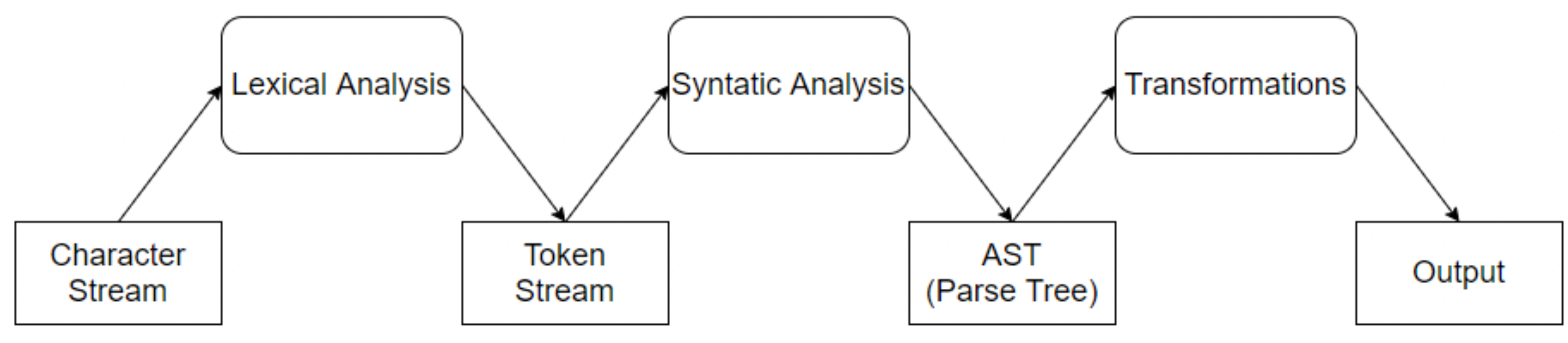
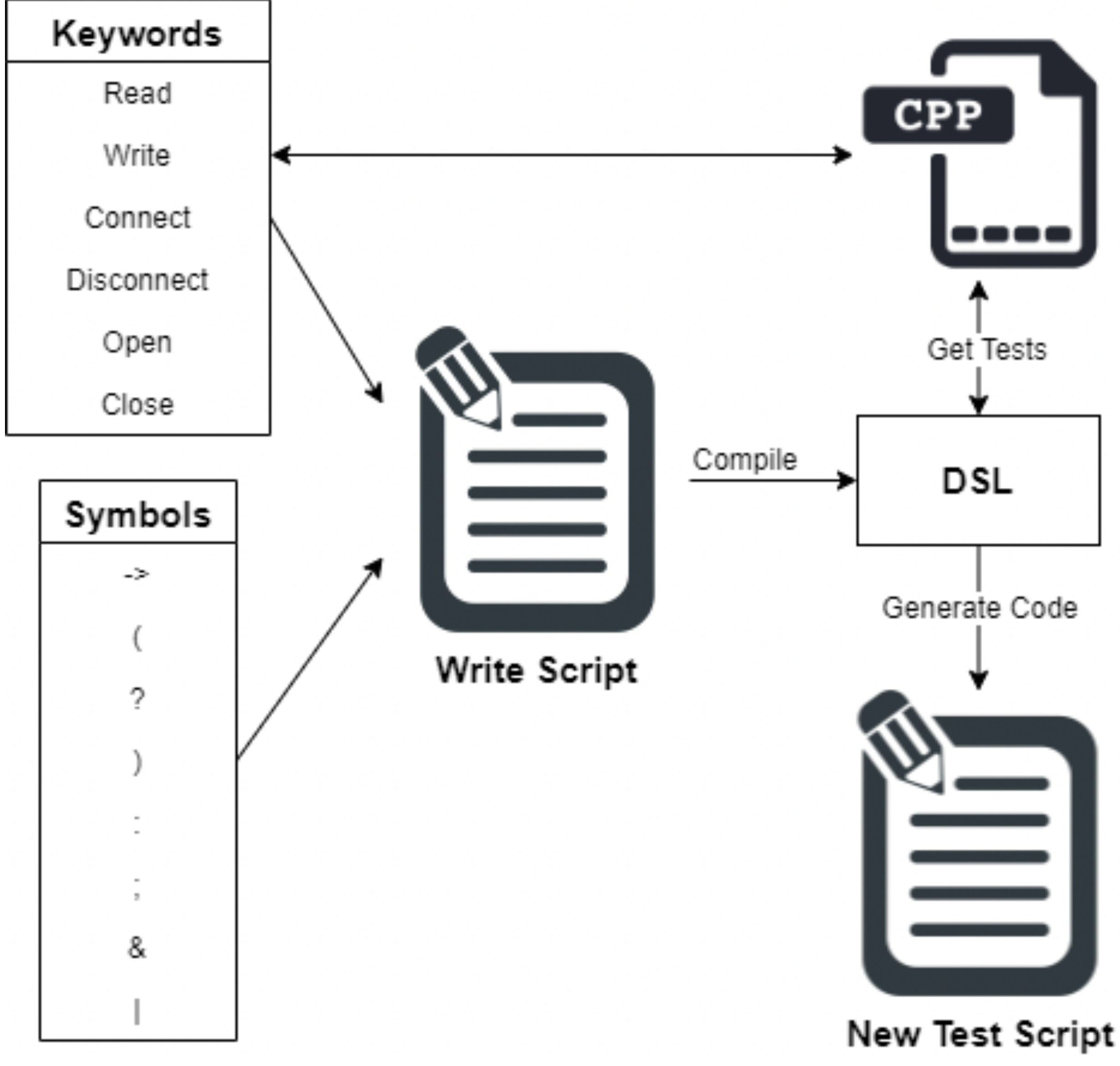
The DSL developed in this paper aims to create new test suites from the primitive tests available in the system, with rules and logic applied, to be executed in the shortest possible time. The language was created from the terminal symbols to identify by the lexer. The parser was created for the rules of logic and sentence construction of the grammar specified. The terminal symbols have been placed in Table 1. The structure of the lexer is shown below in Listing 2:
Listing 2. Grammar Lexer.
                lexer grammar TestLexer;
               
                NEXT : ’->’ ;
                AND : ’&’ ;
                OR : ’|’ ;
               
                IF : ’?’ ;
                ELSE : ’:’ ;
               
                RPAREN : ’)’ ;
                LPAREN : ’(’ ;
               
                END : ’;’ ;
               
                KEYWORD : ([A-Za-z]+([/ _-][A-Za-z]+)*) ;
               
                WS
                    : [ \r\n\t] -> skip ;
          
The structure of the Lexer is quite simple, starting with its identification and then specifying all terminal symbols that must be recognized. These symbols are defined through regular expressions, always ensuring that this definition does not include unexpected elements and, therefore, is not ambiguous.
The symbols we see in this grammar are very intuitive and easy for the end-user to understand, which is one of the objectives. The only symbol that gives any further explanation is the keyword symbol. This symbol must recognize all the names of the primitive tests introduced in the script. Furthermore, its regular expression includes isolated words, thus giving the user some freedom to be more expressive in the choice of keywords. After defining all these factors, it is time to specify the sentence construction rules with these symbols. This is done with the Parser, shown below in Listing 3:
Listing 3. Grammar Parser.
                parser grammar TestParser;
                options {
                    tokenVocab=TestLexer;
                }
                test
                    : statement END ;
                statement
                    : condition #Conditional
                    | seq #Sequence ;
                condition
                    : expr IF statement ELSE statement #IfElse
                    | expr IF statement #If ;
                seq
                    : KEYWORD (NEXT statement)* ;
                expr
                    : LPAREN KEYWORD (AND KEYWORD)* RPAREN #And
                    | LPAREN KEYWORD (OR KEYWORD)* RPAREN #Or ;
          
The parser starts with identification, following the reference for the lexer that provides the symbols to know which are the terminal symbols. After these two steps, the sentences of the grammar are specified. In the element statement, we can see the condition representing a conditional expression and a seq representing a tests sequence. The most important part of the parser to retain is the elements that come at the end of the lines for each possibility determined at the beginning of words by a #. This allows the visitor to know the possible paths in the parsing tree that this parser will generate.
In order for the system can use this grammar, it is necessary to find a way to use it in the system. Since ANTLR offers the transformation of grammar for several programming languages, we will proceed to transform the grammar into JavaScript and include the code directly in the system. For this, it is necessary to execute the following command:
$ antlr4 -Dlanguage = JavaScript Lexer.g4 Parser.g4 -no-listener -visitor
In this command, we specify the lexer and parser to be transformed. After, we define the generation of a visitor. After executing this command, several files will be generated, including the visitor. This is where the code to be developed for the new test suites will be specified, as we can see below, in Listing 4.
Listing 4. Grammar Visitor.
     TestParserVisitor.prototype.visitAnd = function (ctx) {
         this.auxOp = 0;
         for (let i = 0; i < ctx.KEYWORD().length; i++) {
             this.auxList.push(ctx.KEYWORD(i));
         }
         return "";
   };
          
The visitor is to go through the code script through the elements specified in the parser, and each aspect generates the corresponding code. The generated code within the visitor is nothing more than a string incremented and filled up to the end of the parsing tree. All keywords are also saved in a list so that the list and the line containing the generated script are returned at the end. The list of keywords is necessary because it will be necessary to match after generating this code.

5.2.3. Controllers

Controllers are responsible for executing system operations. The way they are structured is similar to models. There is a file for each model accountable for managing the processes related to that collection or model. In each controller, several operations are available according to the needs of each one, but what is common to all is the create, read, update, and delete (CRUD) operations. Besides these operations, there are still more that are particular to only some models, such as the execution of primitive tests, which is an operation developed only in the test controller, the creation of new test suites that make use of the developed DSL and the execution of those identical test suites that are operations defined only in the package controller.
The operations shown below are those mentioned different from the usual CRUD. However, given the context of the system, they are fundamental to its performance:
  • A method to execute a primitive test, passing as arguments the directory where the electronic test drivers are kept, the id of the test to be performed, and the test’s parameters.
A query is made to obtain all the information related to the test, and the execution time count is started. Then, the driver responsible for executing the test is run, which executes it and returns the results. The execution time counts stops as soon as the results arrive, and the test execution time is saved. Finally, some information about the test is added to the results to be held in the reports, and the object containing the results of the test execution is returned (Listing 5):
Listing 5. Execute one primitive test.
          module.exports.runTest = async (driversDirectory, idTest, defaultParam) => {
             let test = await Test.findOne({ _id: idTest }).exec();
             let startTime = process.hrtime()
             exec(‘${driversDirectory}\\${test.module} "${idTest}" "${defaultParam}"‘,
             (err, stdout, stderr) => {
                  if (err) return stderr
                  else {
                      let endTime = process.hrtime(startTime)
                      let result = JSON.parse(stdout)
                      result.runtime = (endTime[1] / 1000000).toFixed(3);
                      result.id_test = idTest;
                      result.module = test.module;
                      result.name = test.name;
                      return result;
                 }
            })
        };
          
  • A method to create a new test suite and insert it into the database, passing an object with the package’s attributes as an argument.
This method starts by using the grammar defined, using the lexer and the parser, to analyze the code script written by the user. Then a parsing tree is created, generated and passed from the visitor of the grammar as an argument. If no error is found in the parsing tree, the visitor will go through that tree and generate the code for the new test suite. After generating the code for the new script, it will be written to a file that will be saved in the directory where the system’s test suites are. Then, the new test suite is also inserted into the database (Listing 6):
Listing 6. Create new test suite.
                module.exports.insertPackage = async (package) => {
                    let chars = new antlr4.InputStream(package.script);
                    let lexer = new Lexer(chars);
                    let tokens = new antlr4.CommonTokenStream(lexer);
                    let parser = new Parser(tokens);
                    parser.buildParseTrees = true;
                    let tree = parser.test();
               
                    if (tree.parser._syntaxErrors === 0) {
                        let listOfTests = await Test.getTests();
                        let visitor = new Visitor(listOfTests);
                        visitor.visitTest(tree);
                        let textFile = visitor.getRes() + "";
                        let t = visitor.getTests();
                        let tests = t.filter(function (elem, pos) {
                            return t.indexOf(elem) == pos;
                        });
                        let fileName = package.name.toLowerCase().replace(/\s/g, ’_’) + ".js";
                        let filePath = scripts_path + fileName;
               
                        fs.writeFile(filePath, textFile, "utf8", function (err) {
                            if (err) throw err;
                            let t = new Package({
                                name: package.name,
                                description: package.description,
                                code: package.script,
                                path: fileName,
                                tests: tests, });
                            return t.save();  });
                    } else {
                        return { errors: tree.parser._syntaxErrors };
                    }
                };
          
  • Method to execute a test suite, passing the ID of the test suite to be run as an argument.
This method starts by querying the package collection for information about the package to be executed. After receiving this information, it only needs to import the test suite code file and call the “run” method that triggers the test suite’s execution. In the end, it waits for the results and returns them (Listing 7).
Listing 7. Execute a test suite.
                module.exports.runPackage = async (idPackage) => {
                    let package = await Package.findOne({ _id: idPackage }).exec();
                    if(package){
                        const file = require("./../public/Packages/" + package.path);
                        return await file.execute();
                    }
                    return {};
                };
          
The operations demonstrated and explained are examples of the different types of procedures that the system performs and supports. However, we can see that all of them have in common that each performs only a specific action that allows us to isolate these actions and reuse them frequently in different parts of the code for other purposes. This will also enable better maintenance of these operations, since whenever it is necessary to make any changes in any of them, it will be done only once and in the indicated location, instead of having to change in different areas, which would easily cause inconsistencies in the code in the long-term.

5.2.4. Routes

The server’s routes, as mentioned previously, are responsible for defining the requests that the client can request, and in this case, they are the ones that receive these requests, forward them to carry out the operations that are necessary to satisfy them, and in the end, send the data to the client. The way the routes are built is based on the URL. For each request, a URL is associated. As the defined API follows the REST architecture, these routes will follow particular and precise formats to notice the type of operation that needs to be executed.
As we saw earlier on controllers, CRUD operations are the most common and on routes. There is also a way to mark requests to determine the category of functions they deal with. In this case, they are HTTP requests. In this system, four types of recommendations have been implemented, namely the get method, responsible for retrieving information from the server using a given uniform resource identifier (URI), a post request used to send data to the server, the put request, which replaces all current representations of the target resource with the uploaded content, and the delete request, responsible for removing all contemporary models of the target resource provided by the URI.
We see all the developed API services available to the client in the previous tables. The implementation of all of them will not be detailed here, but only of some, as a demonstrative example of the implementation format, which is always the same except for some more complex requests. For example, in Listing 8, shown below, we can see the implementation of the route for the get/test request:
Listing 8. Example of GET request implementation.
                router.get("/tests", function (req, res) {
                    Tests.getTests()
                        .then((data) => res.jsonp(data))
                        .catch((error) => res.status(500).jsonp(error));
                });
          
In this example, we see in line 2 the use of “Tests”, which is the reference already imported into the test controller. Then, with this reference, the “getTests” method is called, which is exported in the tests controller. Thus, what is happening is precisely what was described previously. This router forwards the operation to the controller responsible for it. Then, it just waits for the results to arrive to return them to the client.
In Listing 9, shown below, we can see the implementation of the route for the post/packages request:
Listing 9. Example of POST request implementation.
                router.post("/packages", function (req, res) {
                    Packages.insertPackage(req.body)
                        .then((data) => res.jsonp(data))
                        .catch((error) => res.status(500).jsonp(error));
                });
          
In this example, the process is very similar to the previous one. The only difference is that the information saved in the system comes in the request’s body (“req.body”). Therefore, it is necessary to send this information to the method that deals with the operation.
In Listing 10, shown below, we can see the implementation of the route for the put/schedules/:idSchedule request:
Listing 10. Example of PUT request implementation.
                router.put("/schedules/:idSchedule", function (req, res) {
                    Schedules.updateSchedule(req.params.idSchedule, req.body)
                        .then((data) => res.jsonp(data))
                        .catch((error) => res.status(500).jsonp(error));
                });
          
We see the same similarities again in this example, but with a slight difference. Put requests usually bring the identifier of the element that we want to update in the sub-route and, therefore, to have access to it, we must access the request parameters (“req.params”).
In Listing 11, shown below, we can see the implementation of the route for the delete/packages/:idPackage request:
Listing 11. Example of DELETE request implementation.
                router.delete("/packages/:idPackage", function (req, res, next) {
                    Packages.deletePackage(req.params.idPackage)
                        .then((data) => res.jsonp(data))
                        .catch((error) => res.status(500).jsonp(error));
                });
          
In this example, we see the same structure again, but to delete an element from the system, we only need to access the request parameters to obtain the identifier and pass it to the controller.

5.3. Frontend

The frontend is the system level responsible for creating and managing the graphical interfaces. For this system, there are two types of users. The first type of user, more fundamental, will only have access to the execution of primitive tests and test suites. The second type of user, already responsible for managing the system and the test suites, has access to all the other functionalities.
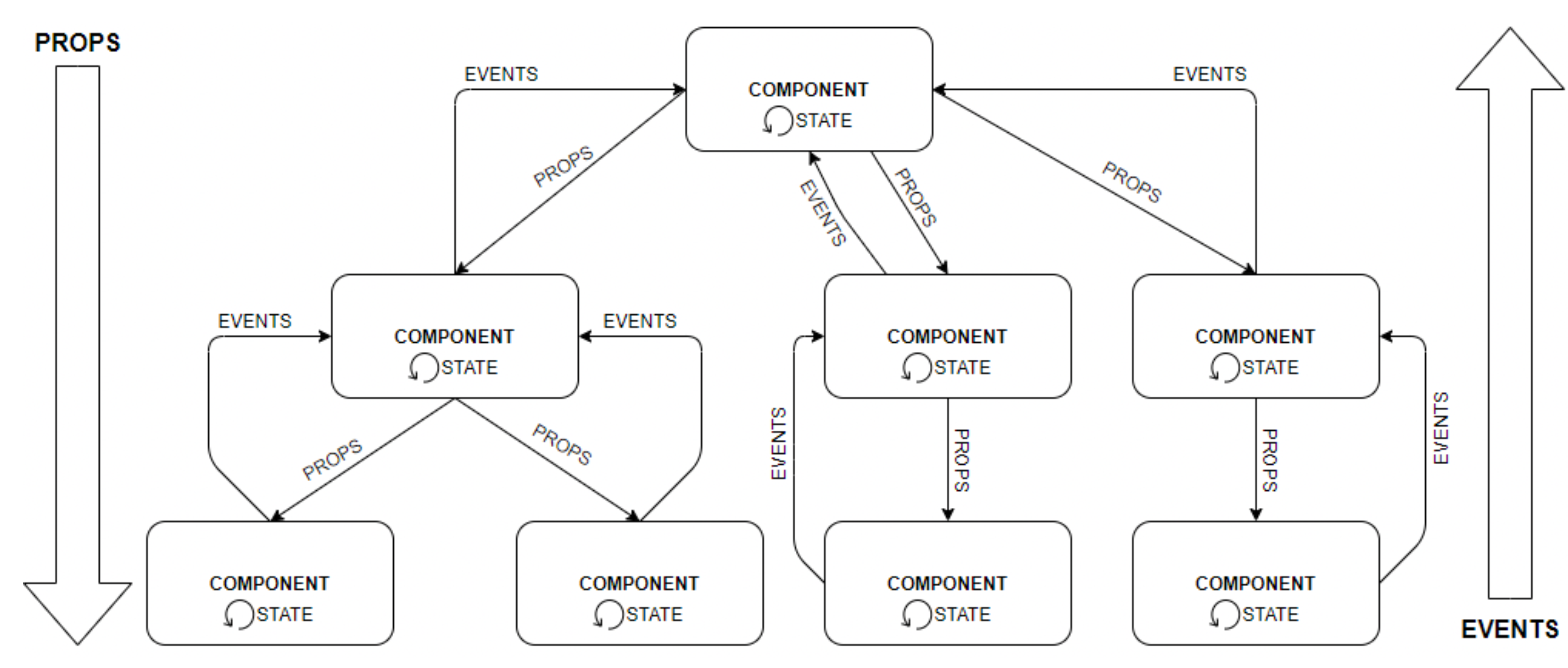
5.3.1. Components

As mentioned, developing components in React becomes an asset. Still, to master the technology, one must understand the fundamentals and how the pieces interact. The three concepts highlighted here are the state of a component is mutable and can be changed by the element itself. These props are the state information of a component and lastly, the events, which are how the child component should inform the parent component of the changes.
Thus, to understand how these concepts apply in practice and make the most of the use of React components, we can see below, in Figure 8, an illustration of how these concepts are related:

5.3.2. Obtaining API Data

Another critical aspect for this part of the system to work as planned is getting the data managed by the backend tier. The graphical interfaces built should be optimized and fast in obtaining data, facilitating the user in this way, because the user does not have to wait long to load the pages, and the data must be obtained in the best way. Here, the decision made was that the parent components of each page make the data requests to the API at the time of its creation. With this, the system pages are that the data are requested and loaded whenever the user changes the page or enters a new page.
The way to obtain the data is through HTTP. To make the code clearer, a file was created only for requesting data from the API. This file contains the base URL of the data API, and all forms add only the route and sub-route. This can be seen below in Listing 12:
Listing 12. Example of request to obtain API data.
            exportt const getTests = async() => {
                try {
                    const reponse = await axios.get(’${url}/tests’);
                    return response.data;
                }   catch   (error) {
                    const statusCode = error.response ? error.response.status : 500;
                    throw new Error(statusCode.toString());
                }
            };
          
This example shows how HTTP requests are made to the API using the imported module “Axios”. Another essential feature that we see in this example is the use of the keyword “await”, which in this particular case makes the method wait for the results of the API.

5.3.3. User Interfaces

The division of access to the pages by each user was carried out through the login on the first page, which will allow assigning a JSON Web Token (JWT) to the user and will only give him access to the appropriate functionalities. After that, the user must enter his ID (provided by CONTROLAR) and enter the proper mode. For example, if it is an operator, it must enter the execution mode, and if it is the system manager, it must enter the configuration mode.
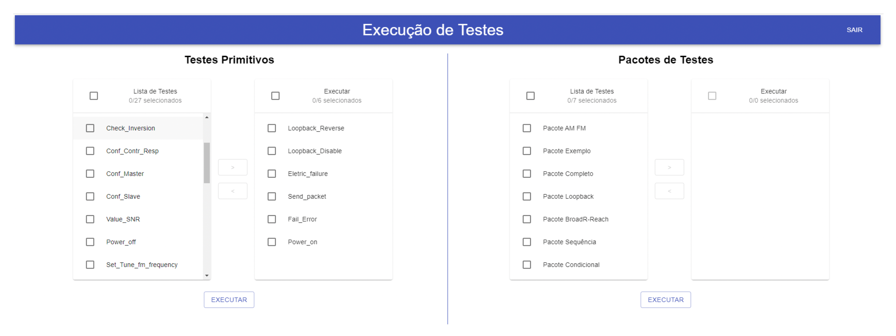
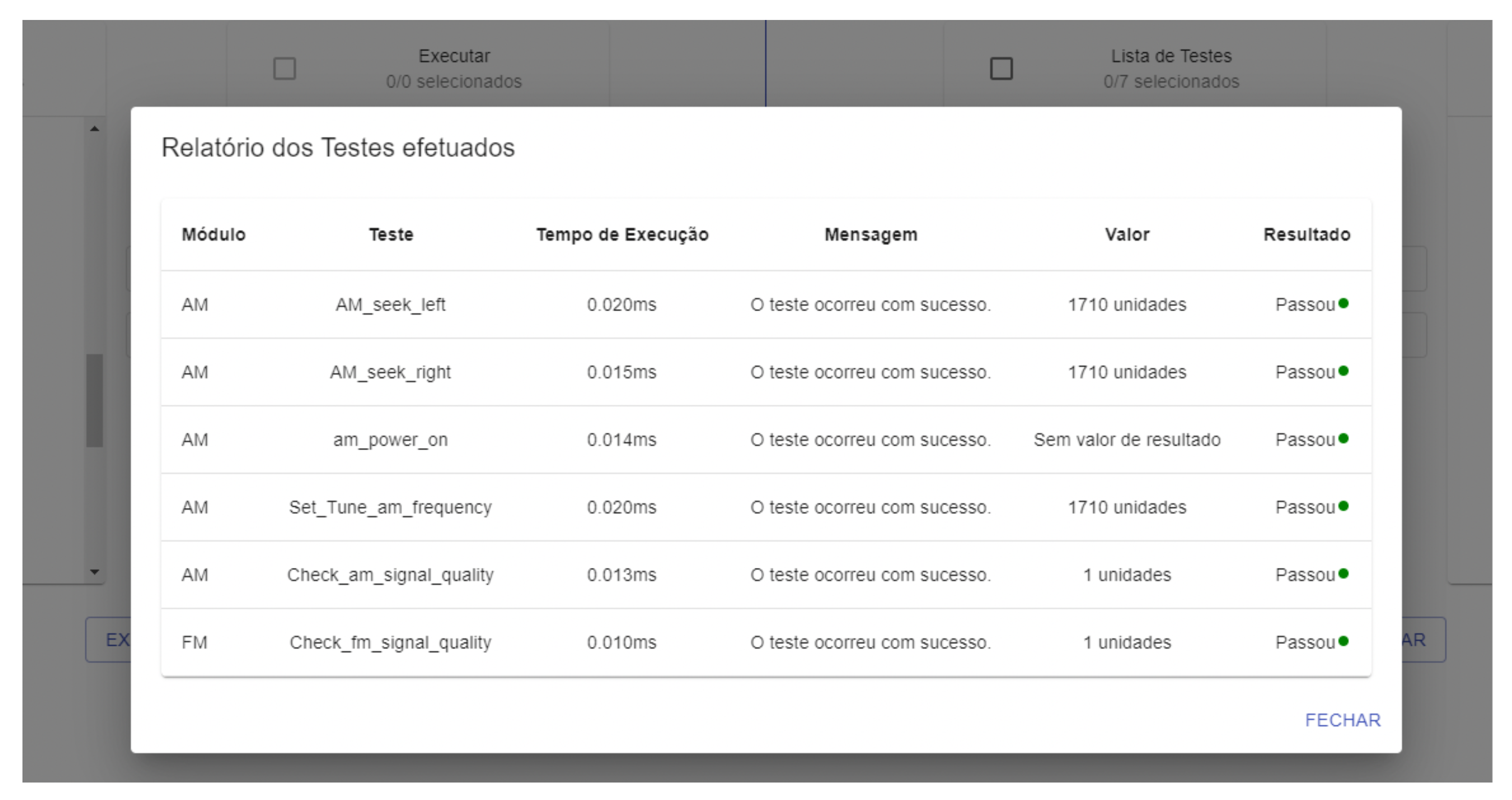
It is only possible to execute primitive tests or test packages on the page available to the operator. The operator has a list of all the primitive tests of the system. To run these tests, they must select the ones they want and execute them all at once. After selecting the tests and passing them to the execution pipe, they need to press a button to run. The system will execute the tests, and, in the end, a table will be presented with the results obtained. The execution interface and the results table shown to the user can be viewed below, in Figure 9 and Figure 10, respectively:
The method described above for selecting and executing primitive tests by the user is the same for the test suites.
The results table shows the execution drivers and some metadata added by the system. The critical metric for the test results is whether the test passed, failed or was inconclusive. The goal of these interfaces is to be as functional and straightforward as possible for decision making.
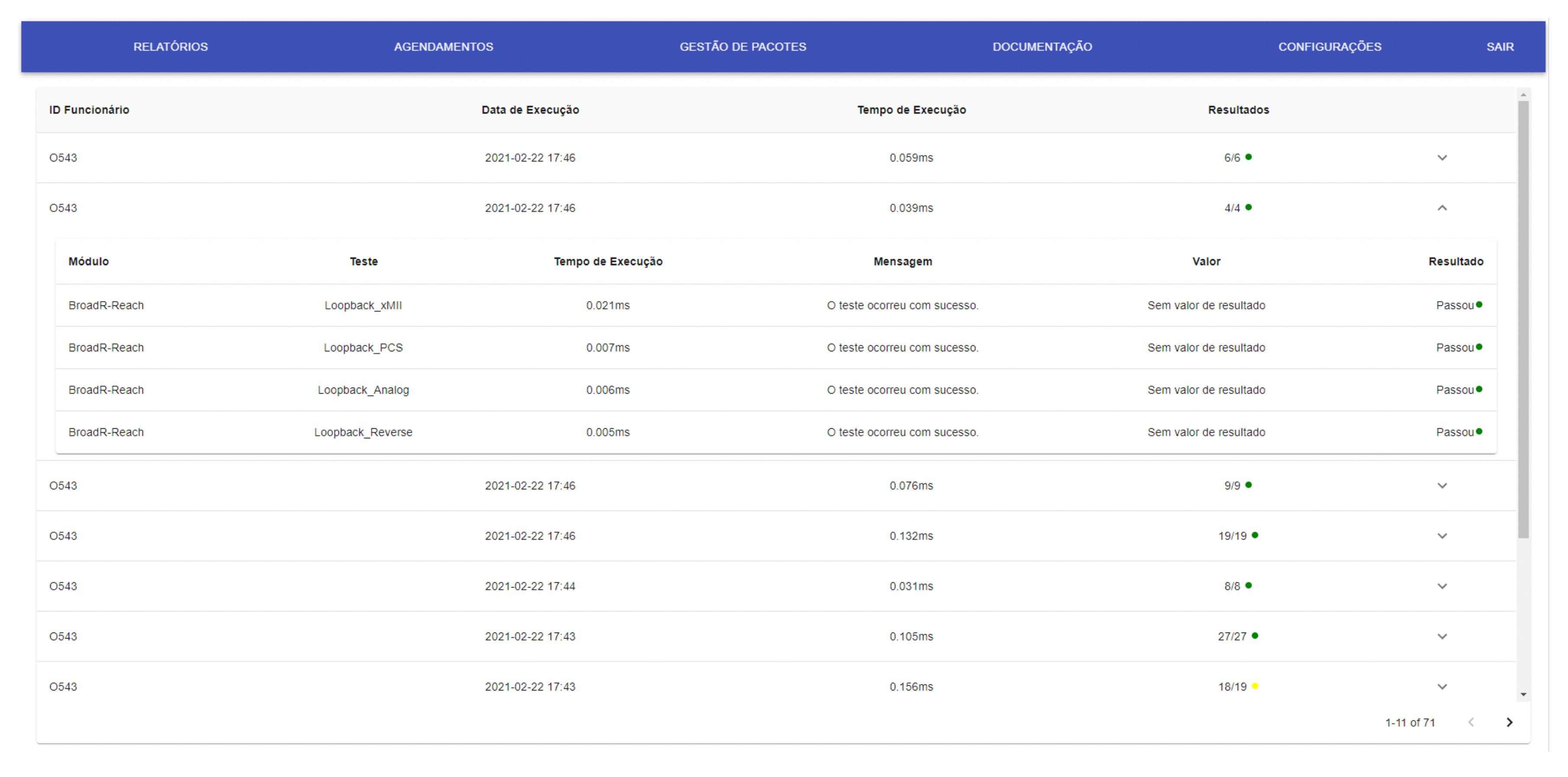
More pages and resources will be accessible to the system manager or administrator. For example, Figure 11 presents the execution report page with the table with all the execution reports made in the system.
Each row in the table allows for expansion that opens an internal table, detailing the results of all tests performed in this report.
The user also has the page for managing and configuring new test suites for the system, which can be seen in Figure 12. On this page, the user has at his disposal the list of existing packages in the system, where he can remove or edit them. There is also a form for creating a new test suite, where the user only needs to specify the name, description and code of the new test suite. The code is written with the DSL.
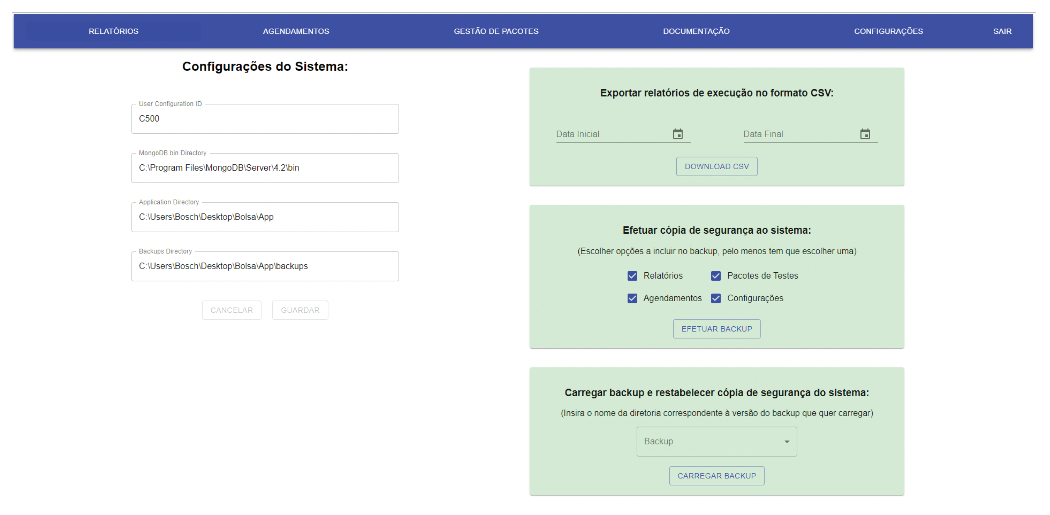
The manager also has a page available where he has access and must update the system settings whenever necessary. These settings are required for the system to work since they are used in fundamental processes. The settings include the the manager ID, which is the only one that has access to this system mode, the MongoDB bin directory, i.e., the directory where the MongoDB executable files are and that allows data extractions and imports, the directory where the system itself is installed, and finally, the directory to where the backups should be exported and also from where they should be imported. For example, this page can be seen in Figure 13:
This page’s features are the management of the system configurations, exporting the system execution reports in CSV format, which can be filtered, making backup copies, customising the data one wants to copy, and restoring backup copies of the system. The backup copies will allow the system to be constantly aware of failure or data corruption situations. However, these features require that the system configurations are correctly completed and correct.

5.4. Validation

The system was implemented with all the established requirements. Several test cases were created to validate the solution and confirm the achievement of the proposed objectives. The first tests were performed on the system’s functionalities, the execution of the tests, and the automation of the update. Then, several test scenarios were simulated, and the system behaved as expected, passing all the tests performed. We can see the tests performed and their results in Table 2.
This table contains the test case line that describes the tests, the testing functionality, and the test steps that the tester must follow strictly to reproduce the same result or attempt. The test data correspond to the data that will be necessary to perform the test. The expected result refers to the effect that the test must achieve to meet the system requirements. The actual impact is the result that the test obtained after the execution and the pass/fail trial.
After carrying out the test cases discussed above, the test cases were performed for all other system features, with the results tables all having the same format. We can see the results and test cases remaining in the following Table 3, Table 4 and Table 5.
In total, 28 test cases covered all the system’s functionality, some of them with more than one test case. No more test cases were carried out because the time it would take to do so is immense, but the test cases performed were considered the most comprehensive cases and, therefore, will give the most excellent coverage of requirements. After analysing all the results obtained in the tests and verifying that they all passed, we can say that all requirements have been successfully implemented. As a result, the system is ready to be integrated with the other components.

5.5. Discussion

As mentioned, the entire implementation of the system was presented in this section. The different system tiers were offered and the technologies, methods, and strategies used to develop a plan that would respond in the best way to all requirements. The entire code was not explained or detailed because it is pervasive, but the most relevant parts were explained, allowing, for those who read it, the reproduction of this work and application in its context. It should also be noted that the developed system is prepared to be integrated with a CPS and with the integration of electronic tests guaranteed and, therefore, ready to carry out the self-diagnosis of the CONTROLAR machines. To validate the implementation of the system and its compliance with the established requirements, 28 test cases were carried out to cover all needs. The results show that all test cases have been approved and, therefore, the system meets all the proposed requirements.

6. Conclusions and Future Work

In the project’s development, we conclude that the main contributions are the architecture design to integrate a self-diagnostic testing system in a CPS and its implementation. An integrated approach will enable the organisation to self-diagnose its machines in real-time, thus ensuring their integrity.
Based on the state-of-the-art analysis, we found that existing solutions for testing systems still focus only on software testing and very little on integrating other categories of tests, hence their integration into CPS. However, in light of the knowledge gained through the analysis of software testing systems and test automation, it is possible to create a plan with some of these characteristics that is designed to be integrated and self-diagnose the CPS. With this, an architecture for the test self-diagnosis system was developed that combines the KDT methodology with a DSL to manage and configure the system tests. This architecture provides a modular and scalable solution to integrate the system with the CPS and perform any test. In addition, another architecture has been designed to extend and integrate the self-testing system into a CPS that proves the modularity of the proposed architecture for the self-testing system by demonstrating how we can develop it in a CPS.
The proposed modular and extensible architecture represents an innovation for self-diagnostic systems and CPS research. It allows combining these two plans using the KDT methodology with a DSL to manage and configure the system tests. Furthermore, this architecture allows tests to be run remotely or by any other system with permission to request HTTP to the REST API. Although the focus of the architecture is the application of a CPS, it is also applicable to any system as it is generic to accept any test. With this work, we have proven that it is possible to integrate self-diagnostic test systems into a CPS with a practical and generic solution combined with other test systems.
The implementation of the system according to the specified requirements, based on the proposed architecture, proves that the system can be modular and allow self-diagnosis by taking any test. To validate the implementation of the system and its compliance with the established requirements, 28 test cases were performed to cover all requirements. The results show that all test cases passed, so the system meets all the proposed requirements. Thus it can be seen that the contributions guarantee security, performance and functionality in using CONTROLAR machines and can now be diagnosed in real-time, allowing customers such as Bosch to make the most of their use in the production environment.

Future Work

It would be interesting to improve the interface for creating new test suites in the system for future work. Although the currently implemented solution is practical and allows for good use, it could be even more functional and straightforward for the user if a drag and drop window were developed to design new test suites instead of writing a code script. Another aspect that could be expanded would be introducing weekly or monthly schedules according to the annual production calendars, which would be even more helpful for this resource.
Although the system is quite complete and correctly implements all the features required by CONTROLAR, there is still a potential for expansion in other types of uses that the company has not explored, such as, for example, the introduction of machine learning/deep learning [48]. For instance, in the future, from the data generated in a production environment, it will be possible to make predictions of the daily or even weekly moments when the machine will be more vulnerable to errors. This topic can be fascinating, as it can give users a better perception of how they should and not use their machines to obtain the best performance from them.

Author Contributions

All authors who contributed substantially to the study’s conception and design were involved in the preparation and review of the manuscript until the approval of the final version. D.F.O., J.P.G. and R.B.P. were responsible for the literature search, manuscript development, and testing. Furthermore, M.A.B. and R.J.M. actively contributed to all parts of the article, including interpretation of results, review and approval. In addition, all authors contributed to the development of the system for the performance of the system tests. All authors have read and agreed to the published version of the manuscript.

Funding

This article is a result of the project POCI-01-0247-FEDER-040130, supported by Operational Program for Competitiveness and Internationalization (COMPETE 2020), under the PORTUGAL 2020 Partnership Agreement, through the European Regional Development Fund (ERDF).

Institutional Review Board Statement

Not applicable.

Informed Consent Statement

Ethics approval is not applicable in this study.

Data Availability Statement

Not applicable in this study. However, the study data sets used or analysed are available in the manuscript tables.

Conflicts of Interest

The authors declare that there are no conflicts of interest regarding the publication of this paper.

References

  1. Lee, E.A. Cyber physical systems: Design challenges. In Proceedings of the 11th IEEE Symposium on Object/Component/Service-Oriented Real-Time Distributed Computing, ISORC 2008, Orlando, FL, USA, 5–7 May 2008. [Google Scholar] [CrossRef]
  2. Pereira, R.B.; Brito, M.A.; Machado, R.J. Architecture Based on Keyword Driven Testing with Domain Specific Language for a Testing System; Springer International Publishing: Berlin/Heidelberg, Germany, 2020; pp. 310–316. [Google Scholar] [CrossRef]
  3. Pereira, R.B.; Ramalho, J.C.; Brito, M.A. Development of self-diagnosis tests system using a DSL for creating new test suites for integration in a cyber-physical system. Open Access Ser. Inform. 2021, 94, 1–16. [Google Scholar] [CrossRef]
  4. Leitão, P. Agent-based distributed manufacturing control: A state-of-the-art survey. Eng. Appl. Artif. Intell. 2009, 22, 979–991. [Google Scholar] [CrossRef]
  5. Minho, U.D. Informação Institucional. 2022. Available online: https://www.uminho.pt/PT/uminho/Informacao-Institucional/Paginas/default.aspx (accessed on 15 August 2022).
  6. Algoritmi, C. Ongoing Projects. 2020. Available online: https://algoritmi.uminho.pt/projects/ongoing-projects/ (accessed on 20 July 2021).
  7. CCG. TSIM—Test System Intelligent Machines. 2020. Available online: https://www.ccg.pt/my-product/tsim-test-system-intelligent-machines/ (accessed on 20 July 2021).
  8. Controlar. Máquina Inteligente de Sistema de Testes Funcionais|Controlar. 2020. Available online: https://controlar.com/areas-de-negocio/sistemas-de-teste/tsim/ (accessed on 20 July 2021).
  9. Seshia, S.A.; Hu, S.; Li, W.; Zhu, Q. Design Automation of Cyber-Physical Systems: Challenges, Advances, and Opportunities. IEEE Trans. Comput. Aided Des. Integr. Circuits Syst. 2017, 36, 1421–1434. [Google Scholar] [CrossRef]
  10. Ngu, A.H.; Gutierrez, M.; Metsis, V.; Nepal, S.; Sheng, Q.Z. IoT Middleware: A Survey on Issues and Enabling Technologies. IEEE Internet Things J. 2017, 4, 1–20. [Google Scholar] [CrossRef]
  11. Vyatkin, V. Software engineering in industrial automation: State-of-the-art review. IEEE Trans. Ind. Inform. 2013, 9, 1234–1249. [Google Scholar] [CrossRef]
  12. Chen, Y.; Kar, S.; Moura, J.M.F. Resilient Distributed Estimation: Sensor Attacks. IEEE Trans. Autom. Control 2019, 64, 3772–3779. [Google Scholar] [CrossRef]
  13. An, L.; Yang, G.H. Enhancement of opacity for distributed state estimation in cyber–physical systems. Automatica 2022, 136, 110087. [Google Scholar] [CrossRef]
  14. Cintuglu, M.H.; Mohammed, O.A.; Akkaya, K.; Uluagac, A.S. A Survey on Smart Grid Cyber-Physical System Testbeds. IEEE Commun. Surv. Tutor. 2017, 19, 446–464. [Google Scholar] [CrossRef]
  15. Asadollah, S.A.; Inam, R.; Hansson, H. A survey on testing for cyber physical system. In Proceedings of the 27th IFIP WG 6.1 International Conference, ICTSS 2015, Sharjah and Dubai, United Arab Emirates, 23–25 November 2015. Lecture Notes in Computer Science (including subseries Lecture Notes in Artificial Intelligence and Lecture Notes in Bioinformatics). [Google Scholar] [CrossRef]
  16. Zhou, X.; Gou, X.; Huang, T.; Yang, S. Review on Testing of Cyber Physical Systems: Methods and Testbeds. IEEE Access 2018, 6, 52179–52194. [Google Scholar] [CrossRef]
  17. Carvalho, M.F.A. Automatização de Testes de Software Dashboard QMSanalyser; Technical Report; Instituto Politecnico de Coimbra: Coimbra, Portugal, 2010. [Google Scholar]
  18. Guru99. Automation Testing Tutorial: What is Automated Testing? 2021. Available online: https://www.guru99.com/automation-testing.html (accessed on 20 July 2021).
  19. Saufi, S.R.; Ahmad, Z.A.B.; Leong, M.S.; Lim, M.H. Challenges and opportunities of deep learning models for machinery fault detection and diagnosis: A review. IEEE Access 2019, 7, 122644–122662. [Google Scholar] [CrossRef]
  20. Shi, Z.; O’Brien, W. Development and implementation of automated fault detection and diagnostics for building systems: A review. Autom. Constr. 2019, 104, 215–229. [Google Scholar] [CrossRef]
  21. Tang, J.; Cao, X.; Ma, A. Towards adaptive framework of keyword driven automation testing. In Proceedings of the IEEE International Conference on Automation and Logistics, ICAL 2008, Qingdao, China, 1–3 September 2008; pp. 1631–1636. [Google Scholar] [CrossRef]
  22. Hametner, R.; Winkler, D.; Zoitl, A. Agile testing concepts based on keyword-driven testing for industrial automation systems. In Proceedings of the IECON 2012—38th Annual Conference on IEEE Industrial Electronics Society, Montreal, QC, Canada, 25–28 October 2012; pp. 3727–3732. [Google Scholar] [CrossRef]
  23. Razak, R.A.; Fahrurazi, F.R. Agile testing with Selenium. In Proceedings of the 2011 5th Malaysian Conference in Software Engineering, MySEC 2011, Johor Bahru, Malaysia, 13–14 December 2011; pp. 217–219. [Google Scholar] [CrossRef]
  24. Tutorials Point. QTP Tutorial—Tutorialspoint. 2021. Available online: https://www.tutorialspoint.com/qtp/index.htm (accessed on 20 July 2021).
  25. Lalwani, T. QuickTest Professional Unplugged, 2nd ed.; KnowledgeInbox, 2011; Available online: https://www.amazon.com/QuickTest-Professional-Unplugged-Tarun-Lalwani/dp/0578025795 (accessed on 20 July 2022).
  26. Kaur, M.; Kumari, R. Comparative Study of Automated Testing Tools: TestComplete and QuickTest Pro. Int. J. Comput. Appl. 2011, 24, 1–7. [Google Scholar] [CrossRef]
  27. Focus, M. Silk Test Automation for Web, Mobile and Enterprise Apps. 2021. Available online: https://www.microfocus.com/en-us/products/silk-test/overview (accessed on 20 July 2021).
  28. Lima, T.; Dantas, A.; Vasconcelos, L. Usando o SilkTest para automatizar testes: Um Relato de Experiência. In Proceedings of the 6th Brazilian Workshop on Systematic and Automated Software Testing, Natal, RN, Brazil, 23 September 2012. [Google Scholar]
  29. Ranorex. Test Automation Tools|Ranorex Automated Software Testing. 2021. Available online: https://www.ranorex.com/test-automation-tools/ (accessed on 20 July 2021).
  30. Jian-Ping, L.; Juan-Juan, L.; Dong-Long, W. Application analysis of automated testing framework based on robot. In Proceedings of the International Conference on Networking and Distributed Computing, ICNDC, Hangzhou, China, 21–24 October 2012; pp. 194–197. [Google Scholar] [CrossRef]
  31. Hermans, F.; Pinzger, M.; Van Deursen, A. Domain-specific languages in practice: A user study on the success factors. In Lecture Notes in Computer Science (Including Subseries Lecture Notes in Artificial Intelligence and Lecture Notes in Bioinformatics); Springer: Berlin/Heidelberg, Germany, 2009; pp. 423–437. [Google Scholar] [CrossRef]
  32. Ciraci, S.; Fuller, J.C.; Daily, J.; Makhmalbaf, A.; Callahan, D. A runtime verification framework for control system simulation. In Proceedings of the 2014 IEEE 38th Annual Computer Software and Applications Conference, Vasteras, Sweden, 21–25 July 2014; pp. 75–84. [Google Scholar] [CrossRef]
  33. Krueger, C.W. Software Reuse. ACM Comput. Surv. (CSUR) 1992, 24, 131–183. [Google Scholar] [CrossRef]
  34. Parr, T.J.; Quong, R.W. ANTLR: A Predicated- LL (k) Parser Generator. Softw. Pract. Exp. 1995, 25, 789–810. [Google Scholar] [CrossRef]
  35. Tomassetti, G. The ANTLR Mega Tutorial. 2021. Available online: https://tomassetti.me/antlr-mega-tutorial/ (accessed on 20 July 2021).
  36. Parr, T.; Fisher, K. LL(*): The foundation of the ANTLR parser generator. ACM Sigplan Not. 2011, 46, 425–436. [Google Scholar] [CrossRef]
  37. Parr, T.; Harwell, S.; Fisher, K. Adaptive LL(*) Parsing: The Power of Dynamic Analysis. ACM Sigplan Not. 2014, 49, 579–598. [Google Scholar] [CrossRef]
  38. Palsberg, J.; Jay, C.B. The Essence of the Visitor Pattern. In Proceedings of the International Computer Software and Applications Conference, Washington, DC, USA, 19–21 August 1998. [Google Scholar] [CrossRef]
  39. Cademy, C. What Is REST?|Codecademy. 2021. Available online: https://www.codecademy.com/articles/what-is-rest (accessed on 20 July 2021).
  40. Costa, B.; Pires, P.F.; Delicato, F.C.; Merson, P. Evaluating a Representational State Transfer (REST) architecture: What is the impact of REST in my architecture? In Proceedings of the Working IEEE/IFIP Conference on Software Architecture 2014, WICSA 2014, Sydney, Australia, 7–11 April 2014; pp. 105–114. [Google Scholar] [CrossRef]
  41. Costa, B.; Pires, P.F.; Delicato, F.C.; Merson, P. Evaluating REST architectures—Approach, tooling and guidelines. J. Syst. Softw. 2016, 112, 156–180. [Google Scholar] [CrossRef]
  42. Subramanian, V. Pro MERN Stack; Apress: New York, NY, USA, 2019. [Google Scholar] [CrossRef]
  43. Inc, F. React—A JavaScript Library for Building User Interfaces. 2021. Available online: https://reactjs.org/ (accessed on 20 July 2021).
  44. Porter, P.; Yang, S.; Xi, X. The Design and Implementation of a RESTful IoT Service Using the MERN Stack. In Proceedings of the 2019 IEEE 16th International Conference on Mobile Ad Hoc and Smart Systems Workshops, MASSW 2019, Monterey, CA, USA, 4–7 November 2019; pp. 140–145. [Google Scholar] [CrossRef]
  45. Aggarwal, S. Modern Web-Development using ReactJS. Int. J. Recent Res. Asp. 2018, 5, 133–137. [Google Scholar]
  46. Javeed, A. Performance Optimization Techniques for ReactJS. In Proceedings of the 2019 3rd IEEE International Conference on Electrical, Computer and Communication Technologies, ICECCT 2019, Coimbatore, India, 20–22 February 2019; pp. 1–5. [Google Scholar] [CrossRef]
  47. Obinna, E. Use the React Profiler for Performance. 2018. Available online: https://www.digitalocean.com/community (accessed on 20 July 2021).
  48. Oliveira, D.F.; Brito, M.A. Position Paper: Quality Assurance in Deep Learning Systems; SciTePress: Setúbal, Portugal, 2022; pp. 203–210. [Google Scholar] [CrossRef]
Figure 1. Diagram of a language processor.
Computers 11 00131 g001
Figure 2. Object Mapping between Node.js and MongoDB managed via Mongoose.
Computers 11 00131 g002
Figure 3. Real DOM and React Virtual DOM.
Computers 11 00131 g003
Figure 4. KDT approach.
Computers 11 00131 g004
Figure 5. Proposed architecture for KDT with DSL.
Computers 11 00131 g005
Figure 6. Architecture for self-diagnosis test system.
Computers 11 00131 g006
Figure 7. Architecture for a self-diagnosis test system integrated with the CPS.
Computers 11 00131 g007
Figure 8. Interactions between components.
Computers 11 00131 g008
Figure 9. Execution page.
Computers 11 00131 g009
Figure 10. Execution Results Table.
Computers 11 00131 g010
Figure 11. Report page.
Computers 11 00131 g011
Figure 12. Package management page.
Computers 11 00131 g012
Figure 13. System configurations page and data export and import.
Computers 11 00131 g013
Table 1. DSL Symbols.
SymbolDescription
keywordCatches the keywords in the script
> Catches the “next”symbol, which means that after that symbol, the next block to be executed arrives
(Catches the opening parenthesis
)Catches the closing parenthesis
?Catches the conditional expressions from the script
:Catches the next block of code to be executed when a condition is false
&Catches the logical operator that means intersection
|Catches the logical operator that means union
;Catches the end of the script
Table 2. Results of test cases performed on test executions and management.
Test CaseTest StepsTest DataExpected ResultActual ResultsPass/Fail
Check the execution of primitive tests1. Select tests to execute 2. Click the button to run 3. When window to confirm appears, select yesTests selected: am_power_on set_frequency am_seek_leftA table with the test results must appearTable presented with the resultsPass
Check the execution of all primitive tests1. Select all tests to execute 2. Click the button to run 3. When window to confirm appears, select yesTests selected: all availableA table with all the test results must appearTable presented with all resultsPass
Check for a message when no test is selected to notify1. Click button to execute without selecting testsNoneA warning message should appear notifying you that the user has not selected any testsMessage appeared with the notificationPass
Check if system updates the removed primitive tests1. Go to the electronic test drivers directory 2. Remove driverA.json from directory 3. Open the system in the execution mode 4. Check if tests of driver A are availableNoneTests from driver A must not appear to be selectedTests are not availablePass
Check if system updates the added primitive tests1. Go to the electronic test drivers directory 2. Add driverA.json from directory 3. Open the system in execution mode 4. Check if tests of driver A are availableNoneTests from driver A must appear to be selectedTests are availablePass
Check the execution of a test suite1. Select test suite to execute 2. Click the button to runTest suites selected: Pacote AM FMA table with the test suite results must appearTable presented with the resultsPass
Check the execution of all test suites1. Select all test suites to execute 2. Click the button to run 3. When window to confirm appear, select yesTest suites selected: all availableA table with the all test suite results must appearTable presented with all resultsPass
Check for a message when no test suite is selected to notify1. Click button to execute without selecting testsNoneA warning message should appear notifying you that the user has not selected any test suitesMessage appeared with the notificationPass
Table 3. Results of test cases performed on visualization reports, documentation of primitive tests and scheduling of executions.
Test CaseTest StepsTest DataExpected ResultActual ResultsPass/Fail
Check the execution reports1. Open tab “Relatórios”NoneA table with the all reports must appearTable presentedPass
Check the details of an execution report1. Open tab “Relatórios” 2. Choose a report and click on itNoneA table with the evidence of the results of the tests carried out in that report must be presentedTable presentedPass
Check documentation of primitive tests1. Open tab “Documentação”NoneA table with all primitive test metadata must be presentedTable presentedPass
Check the schedule of a new execution1. Click in the button to add schedule 2. Enter time 3. Activate the option button 4. Select the primitive tests to execute 5. Select the test suites to execute 6. Click on the save buttonTime: 8:00 Active: True Tests Selected: power_on set_fm_frequency fm_seek_rightA new schedule must be added to the systemSchedule createdPass
Check scheduling a new execution without selecting any test1. Click on the button to add schedule 2. Enter time 3. Activate the option button 4. Click on the save buttonTime: 10:00 Active: TrueAn error message must appear stating that at least one test must be selectedMessage appearedPass
Check the update of a schedule1. Click on the schedule timed to 8:00 2. Change time to 9:00 3. Click on the save buttonTime: 9:00The schedule must be updatedSchedule createdPass
Check the removal of a schedule1. Click on the option button to remove the schedule timed to 9:00NoneThe schedule must be removedSchedule createdPass
Table 4. Results of test cases performed in managing and creating test suites and exporting reports to CSV.
Test CaseTest StepsTest DataExpected ResultActual ResultsPass/Fail
Check the creation of a new test suite with wrong script1. Open tab “Gestão de Pacotes” 2. Enter package name 3. Enter package description 4. Write the script 5. Click on the save buttonPackage Name: Novo Pacote Package Description: Pacote para demonstrar erro Package Script: InventedTest > a m _ p o w e r _ o n > An error alert must appear to the user saying the code is not correctAlert shownPass
Check the creation of a new test suite1. Open tab “Gestão de Pacotes” 2. Enter package name 3. Enter package description 4. Write the script 5. Click in the save buttonPackage name: New Package Package description: Package for demonstration Package script: p o w e r _ o n > am_power_on;Test suite must be created and should appear in the list on the left sideTest suite created and availablePass
Check the update of a test suite1. Open tab “Gestão de Pacotes” 2. Click on the package named ”New Package” 3. Click on the edit button 4. Change the name 5. Click on the save buttonPackage name: New Package to RemoveTest suite must be updatedTest suite updatedPass
Check the removal of a test suite1. Open tab “Gestão de Pacotes” 2. Click on the package named ”New Package to remove” 3. Click on the remove buttonNoneTest suite must be removedTest suite removedPass
Check the export of reports to a CSV with dates not covered1. Open tab “Configurações” 2. Enter begin date on export CSV 3. Enter end date on export CSV 4. Click download buttonBegin date: 25 July 2021 End date: 1 September 2021A CSV file must be downloaded without linesCSV file was downloaded with no linesPass
Check the export of reports to a CSV1. Open tab “Configurações” 2. Enter begin date on export CSV 3. Enter end date on export CSV 4. Click download buttonBegin date: 1 January 2021 End date: 1 August 2021A CSV file must be downloaded that contains all the reports from the specified intervalCSV file downloaded with the all reports from the intervalPass
Table 5. Results of test cases performed on system backups, restoring backup versions and managing system configurations.
Test CaseTest StepsTest DataExpected ResultActual ResultsPass/Fail
Check system backup, including schedules and packages1. Open tab “Configurações” 2. Include packages and schedules 3. Click on the make backup buttonNoneA zip file must be saved in the backup directory specified in the system configurations and a success message should appearZip file successfully saved to the backup directory and the success message appearedPass
Check system backup, including all system data1. Open tab “Configurações” ” 2. Include all options 3. Click on the make backup buttonNoneA zip file must be saved in the backup directory specified in the system configurations and a success message should appearZip file successfully saved to the backup directory and the success message appearedPass
Check the system backup, with incomplete system configurations fields1. Open tab “Configurações” ” 2. Include all options 3. Click on the make backup buttonNoneAn error message must appear informing that all fields of system configurations must be completedError message appeared stating that all fields must be completedPass
Check the restore of a backup in the system, including schedules and packages1. Open tab “Agendamentos” 2. Delete the 8:00 schedule 3. Open tab “Gestão de Pacotes” 4. Delete package with name “Pacote Exemplo” 5. Open tab “Configurações” 6. Select backup to restore with name ending with substring ”_sp” 7. Click the button to make a restoreNoneThe removed schedules and packages must be on the system again and a success message should appearSchedules and packages have been re-established and the message of success has appearedPass
Check the restore of a backup in the system, including all data1. Open tab “Agendamentos” 2. Delete all schedules 3. Open tab “Gestão de Pacotes” 4. Delete all packages 5. Open tab “Configurações” 6. Select backup to restore with name ending with substring”_crsp” 7. Click the button to make a restoreNoneThe removed elements must be on the system again and a success message should appearAll data were re-established and the message of success has appearedPass
Check the restore of a backup in the system with incomplete fields on system configurations1. Open tab “Configurações” 2. Select backup to restore 3. Click the button to make a restoreNoneAn error message must appear informing that all fields of system configurations must be completedError message appeared stating that all fields must be completedPass
Check the update of system configurations1. Open tab “Configurações” 2. Delete the backup directory 3. Click the save buttonNoneBackup directory must be emptyBackup directory is emptyPass
Publisher’s Note: MDPI stays neutral with regard to jurisdictional claims in published maps and institutional affiliations.

