Article

Performance Analysis and Optimization of an InGaAs/GaAsSb Heterojunction Dopingless Tunnel FET with a Heterogate Dielectric

1
Key Laboratory for Wide Band Gap Semiconductor Materials and Devices of Education, School of Microelectronics, Xidian University, Xi’an 710071, China
2
Science and Technology on Reliability Physics and Application Technology of Electronic Component Laboratory, China Electronic Product Reliability and Environmental Testing Research Institute, Guangzhou 511370, China
*
Author to whom correspondence should be addressed.
Micromachines 2025, 16(12), 1330; https://doi.org/10.3390/mi16121330
Submission received: 24 October 2025 / Revised: 22 November 2025 / Accepted: 25 November 2025 / Published: 26 November 2025
(This article belongs to the Section D1: Semiconductor Devices)

Abstract

An InGaAs/GaAsSb heterojunction dopingless Tunnel FET with a heterogate dielectric is proposed and investigated in this work, aiming to extend the advantages of dopingless TFETs in low-power applications. By employing the InGaAs/GaAsSb heterojunction with a quasi-broken gap energy band structure in dopingless TFET, the HDL-TFET achieves extremely high band-to-band tunneling efficiency. A dual-electrode structure is adopted to improve carrier distribution, which further enhances tunneling efficiency and increases on-state current (ION). To suppress off-state tunneling, optimize ambipolar current, and reduce parasitic capacitance, a heterogate dielectric structure is introduced. Results show that the HDL-TFET exhibits an ION up to 8.33 × 10⁻⁵ A/μm and a steep subthreshold swing (SSavg) of 10.18 mV/dec at a low operating voltage of 0.5 V. It also achieves an off-state current (IOFF) as low as 3.42 × 10⁻¹⁵ A/μm and ION/IOFF ratio up to 2.44 × 10¹⁰, with no obvious ambipolar current. Compared with previously reported works, the proposed HDL-TFET demonstrates significant advantages. Additionally, the introduction of the heterogate dielectric and dual-electrode structure significantly improves the RF performance of the device, with a peak transconductance (Gm) of 333 μS/μm, and a peak cutoff frequency (fT) and gain bandwidth product (GBP) up to 64 GHz and 49 GHz, respectively.

1. Introduction

Unlike traditional MOSFETs, TFETs primarily rely on the band-to-band tunneling (BTBT) mechanism for current conduction. This mechanism can effectively break the limitation of thermionic emission and achieve a subthreshold swing lower than 60 mV/dec, making TFET ideal logic devices for low-power applications [1,2,3,4]. To improve device performance, conventional TFETs require an extremely steep doping concentration gradient at the tunneling junction. This requirement leads to high thermal budgets during fabrication and performance degradation caused by random doping fluctuations [5,6]. To address these issues, dopingless TFETs have been extensively studied [7,8,9,10,11,12]. In dopingless TFET, the source and drain regions are formed based on the concept of charge plasma [13] by configuring different electrode work functions. This design avoids the high process requirements imposed by abrupt junctions and the impact of random doping fluctuations.
Another issue limiting TFET performance is the relatively low on-state current (ION) [14,15]. Among semiconductor materials, III-V compounds exhibit great potential due to their small effective mass and broken or staggered band alignment. These properties enable higher ION and a more optimized ION/IOFF ratio [16,17]. To achieve better TFET performance, many researchers have conducted in-depth studies on heterojunction TFETs based on various III-V materials, such as GaSb/InAs [18,19,20], InGaAs/GaAsSb [21,22], InGaAs/InAlAs [23], and InGaAs/InP [24]. However, most of these studies focus on conventionally doped TFET, while research on dopingless TFETs remains relatively limited. Only Reference [25] has investigated a similar structure, but the proposed structure does not leverage the advantages of the quasi-broken gap energy band. Its tunneling junction is entirely composed of GaAsSb, and the device performance is improved through the material’s inherently small band gap—this operating mechanism is completely different from that of the device studied in this work. Moreover, the performance of the device studied in this work is further improved compared with that in Reference [25].
In this work, a dopingless TFET structure (HDL-TFET) based on the InGaAs/GaAsSb heterojunction is proposed, and its DC and RF performances are investigated. Benefiting from the quasi-broken gap energy band structure of the InGaAs/GaAsSb heterojunction and the process advantages of dopingless TFET, the HDL-TFET achieves both simple fabrication and large on-state current with low subthreshold swing at low operating voltage. Additionally, the heterogate dielectric and dual-electrode structure significantly enhance the device’s DC and RF performances, making the proposed HDL-TFET highly promising for low-power applications.

2. Device Structure and Model

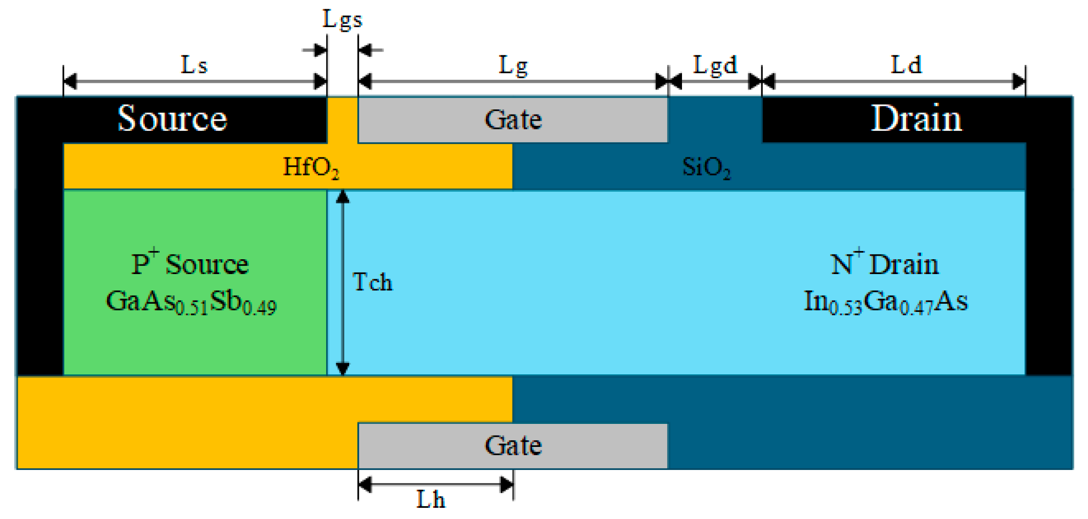
The device structure of the HDL-TFET is illustrated in Figure 1. The tunneling junction consists of a P+ GaAs0.51Sb0.49 source region and an intrinsic In0.53Ga0.47As channel region. The In0.53Ga0.47As/GaAs0.51Sb0.49 heterojunction epitaxial layer is lattice-matched to the InP substrate [26], which helps reduce the defect density at the heterojunction interface and maintains the device’s excellent off-state performance. Therefore, the material composition adopted in this work is In0.53Ga0.47As/GaAs0.51Sb0.49. Meanwhile, the HDL-TFET adopts a dual-electrode and heterogate dielectric structure, achieving outstanding DC and RF performances while suppressing off-state tunneling and reducing the impact of ambipolar current.
Relevant structural parameters are listed in Table 1. Based on the principle of charge plasma, the source work function is set to 5.0 eV to induce a high concentration of holes in the source region, forming an equivalent heavily doped P+ source. The drain work function is set to 4.4 eV to induce a low concentration of electrons in the drain region, forming an equivalent lightly doped N+ drain. The gate-source length (Lgs) is 5 nm, and the gate-drain length (Lgd) is 15 nm. The larger Lgd and lightly doped N+ drain are beneficial for achieving lower ambipolar current.
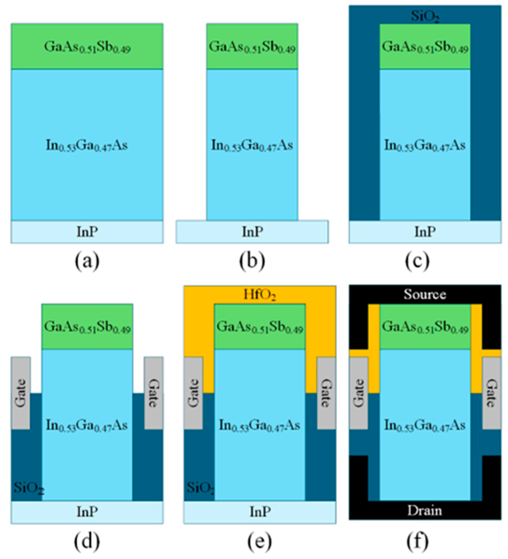
Figure 2 illustrates the key fabrication process flow of the HDL-TFET. In Figure 2a, In0.53Ga0.47As and GaAs0.51Sb0.49 are epitaxially grown on the InP substrate. In Figure 2b, inductively coupled plasma (ICP) etching technology is used to form the GaAs0.51Sb0.49/ In0.53Ga0.47As heterojunction, which serves as the bulk material of the HDL-TFET. In Figure 2c, a SiO2 oxide layer is deposited via atomic layer deposition (ALD) technology. In Figure 2d, the SiO2 oxide layer is etched, and the gate electrode is deposited using ALD technology. In Figure 2e, a HfO2 oxide layer is deposited by ALD technology. In Figure 2f, the HfO2 oxide layer is first etched, followed by the deposition of the source metal in the etched region. The formation of the drain metal electrode can be accomplished via substrate lift-off technology, followed by etching of the SiO2 oxide layer and deposition of the drain metal, or alternatively via substrate thinning combined with via-hole technology [23], ultimately resulting in the device structure depicted in Figure 1.
Device simulations of the HDL-TFET were performed using the Silvaco ATLAS TCAD tool. To account for the spatial variation in energy bands, a non-local band-to-band tunneling model was employed in the simulations to more accurately simulate the tunneling process. The Lombardi mobility model, Fermi–Dirac carrier statistics, Shockley–Read–Hall recombination, band gap narrowing, and Auger recombination models were included in the simulations. Additionally, concentration-dependent and field-dependent mobility models, as well as trap-assisted tunneling models, were incorporated to provide simulation results that are closer to real-world behavior.

3. Results and Discussion

3.1. Operating Mechanism of the HDL-TFET

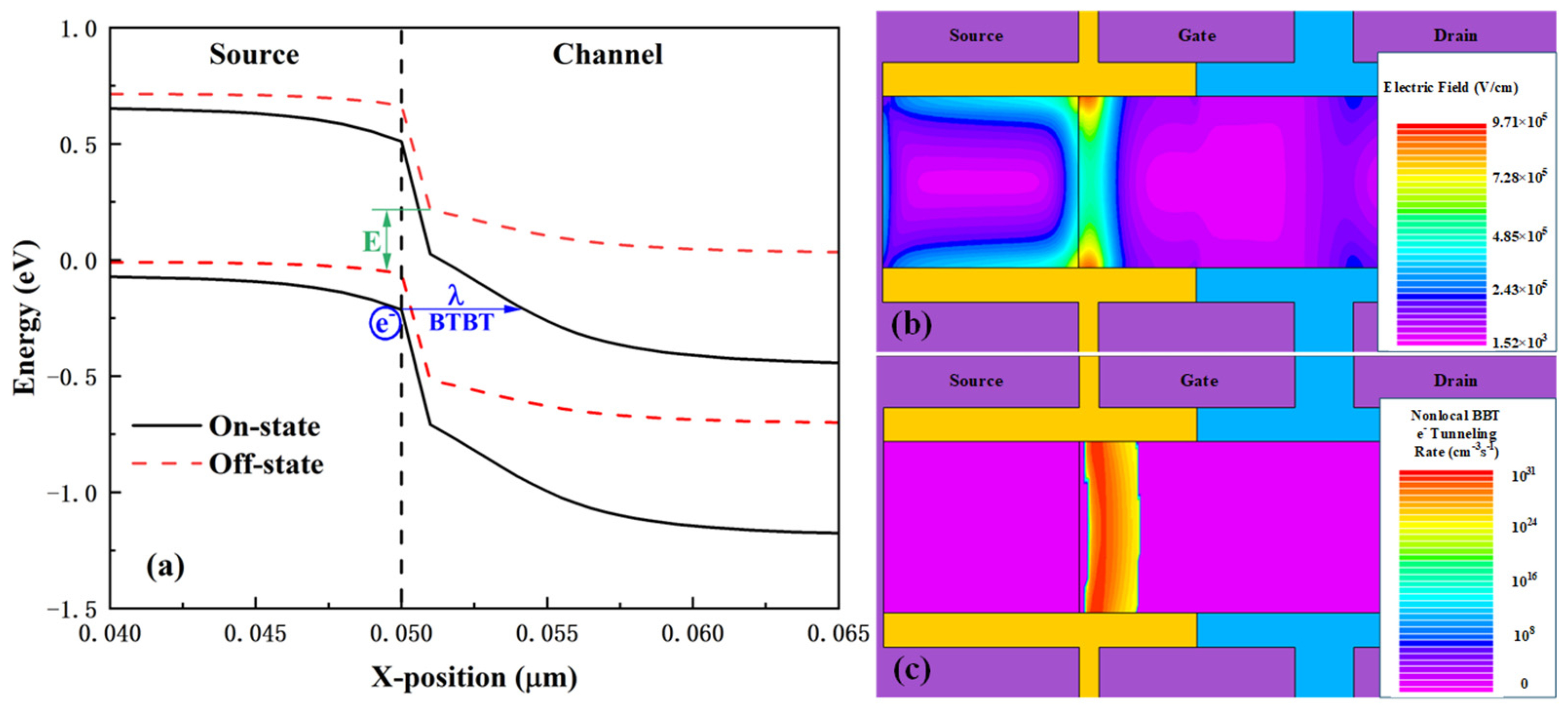
Figure 3 illustrates the operating mechanism of the HDL-TFET. The energy band structures 1 nm below the gate dielectric near the tunneling junction are plotted in Figure 3a for both the off-state (Vds = 0.5 V, Vgs = 0 V) and on-state (Vds = 0.5 V, Vgs = 0.5 V) of the device. In the off-state, there is no overlap between the conduction band of the channel and the valence band of the source region near the tunneling junction, which suppresses BTBT. As Vgs increases, the conduction band edge of the channel drops below the valence band edge of the source region. This induces BTBT, where electrons tunnel from the source region to the channel, generating a tunneling current. In Figure 3a, E = 0.27 eV represents the energy difference between the conduction band and valence band at the tunneling junction in the off-state, while λ = 3.96 nm denotes the minimum tunneling distance at the tunneling junction in the on-state. Benefiting from the quasi-broken gap energy band structure of the In0.53Ga0.47As/GaAs0.51Sb0.49 heterojunction, both E and λ exhibit extremely small values. This indicates that compared with conventional tunneling junctions, the tunneling junction of the HDL-TFET is easier to turn on, allowing the device to operate at lower gate voltages while achieving higher tunneling currents.
From Figure 3a, it can also be observed that the conduction band and valence band of the source region exhibit a certain degree of downward shift in the on-state, which can be explained by Figure 3b. Figure 3b presents the electric field distribution in the bulk material during the on-state. It is evident that the electric field is mainly concentrated at the heterojunction, which is conducive to the HDL-TFET, achieving a larger on-state current. Meanwhile, the electric field shows a high distribution at the surface of the source region, which accounts for the downward shift in the source region’s conduction and valence bands. Figure 3c illustrates the distribution of the electron tunneling rate in the on-state. It is easy to see that due to the adoption of the heterojunction and dual-electrode symmetric structure, the device exhibits extremely high electron tunneling rates both at the surface and in the bulk along the vertical direction, even though it has a point tunneling structure. BTBT occurs across the entire heterojunction interface.
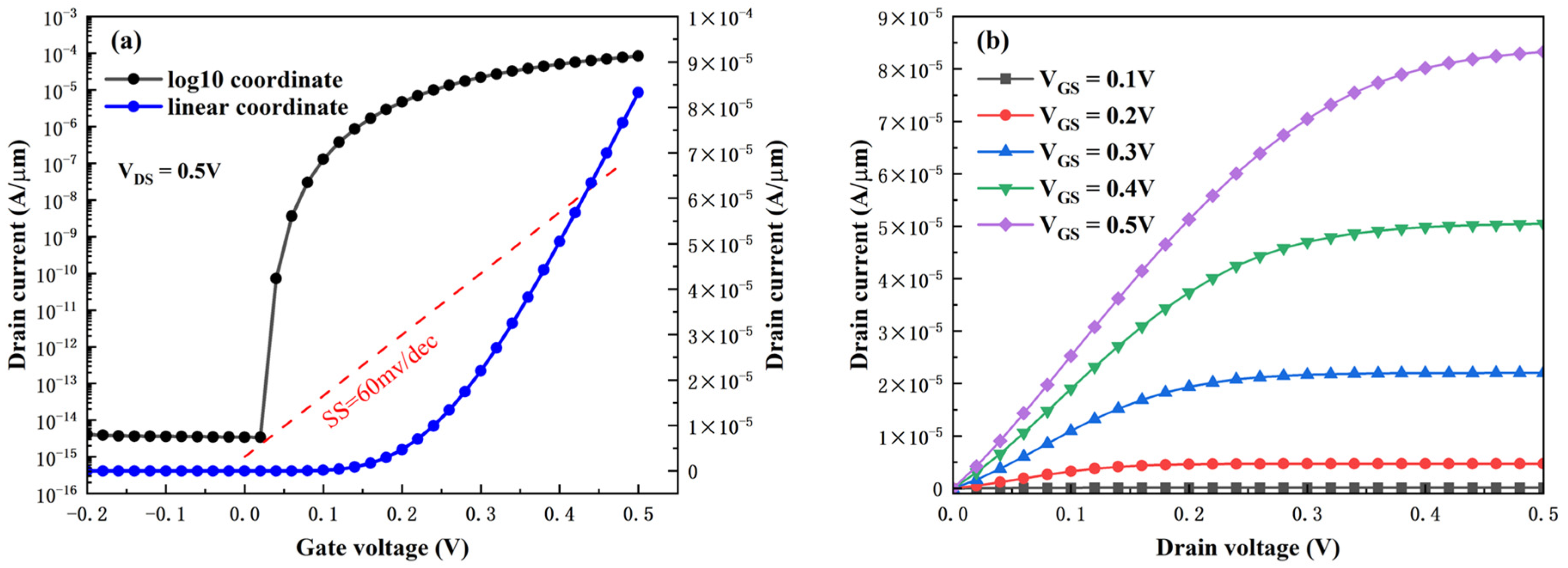
Figure 4a,b present the transfer characteristic curve and output characteristic curve of the HDL-TFET, respectively. Owing to the operating mechanism mentioned earlier, the device exhibits excellent DC performance. It can operate at a low voltage of 0.5 V, achieving a high ION up to 8.33 × 10⁻⁵ A/μm. Meanwhile, the heterogate dielectric and lightly doped N+ drain structure suppress off-state tunneling, resulting in an ultra-low IOFF of 3.42 × 10⁻¹⁵ A/μm. No obvious ambipolar current is observed within a certain negative voltage range.
S S a v g = V t h V o f f l o g ( I t h ) l o g ( I o f f )
The average subthreshold swing (SSavg) of the device is calculated using Equation (1), where the voltage corresponding to a drain current (Ith) of 1 × 10⁻⁷ A/μm is taken as the threshold voltage (Vth). The resulting SSavg is 10.18 mV/dec, which is far below the 60 mV/dec limit of MOSFETs.

3.2. Effect of Device Parameters on Performance

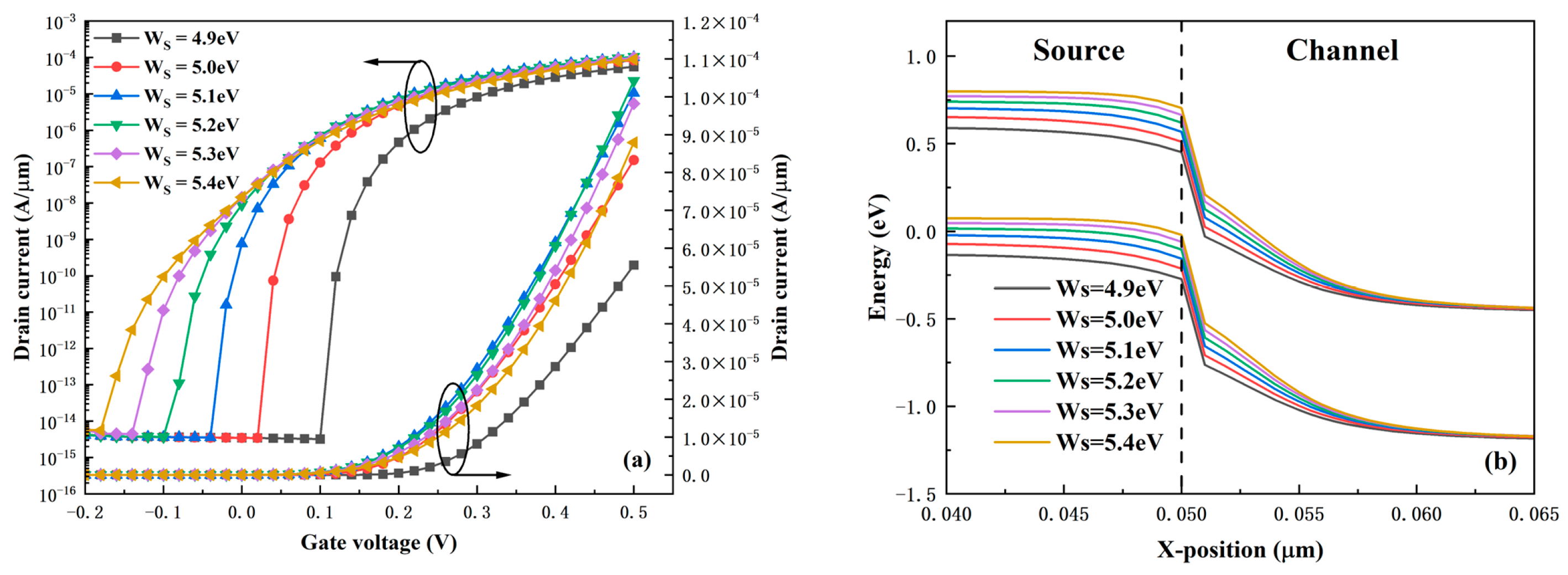
Figure 5a shows the transfer characteristic curves of the HDL-TFET under different source work functions Ws. It can be observed that the transfer curves shift gradually to the left as Ws increases. This phenomenon is easy to understand: with the increase of Ws, the conduction band and valence band of the source region shift upward, leading to a lower turn-on voltage of the tunneling junction and easier formation of the BTBT path. Meanwhile, it is found that the subthreshold swing of the device increases with the increase of Ws. The ION increases gradually when Ws is less than 5.2 eV, but starts to decrease when Ws exceeds 5.2 eV. As shown in Equation (2), based on the WKB approximation [27], the tunneling probability depends on the effective tunneling length λ and the effective tunneling window ∆Φ.
T W K B e x p ( 4 λ 2 m * E g 3 3 q ( E g + Φ ) )
From the on-state energy band diagram in Figure 5b, it can be observed that although the effective tunneling window ∆Φ increases with the rise in the Ws, the effective tunneling length λ also increases as Ws increases. These two factors exert opposite effects on the tunneling probability. As a result, the variation in current is not as drastic as that of voltage, leading to the phenomena where the subthreshold swing increases and the ION first rises and then decreases.
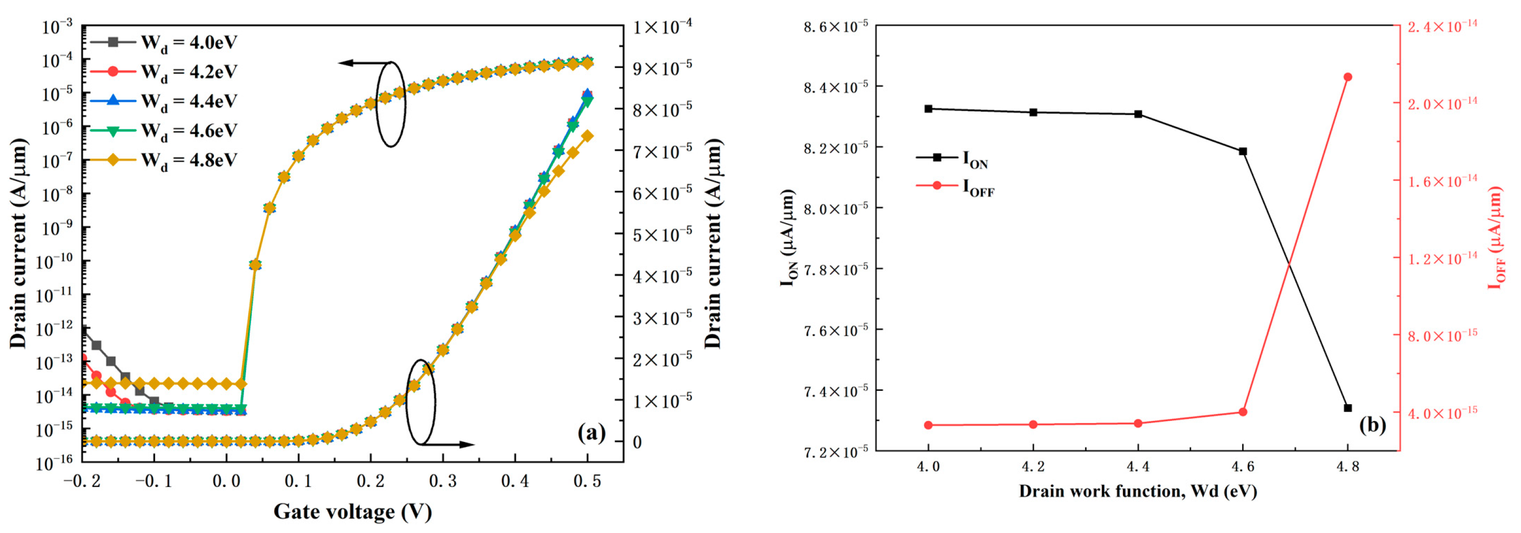
Figure 6 presents the performance variations in the HDL-TFET under different drain work functions Wd. The results indicate that the device is not sensitive to changes in Wd. When Wd is less than 4.6 eV, there are no obvious changes in the ION and IOFF of the device. The most significant change is that the ambipolar current decreases with the increase of Wd—this is because the reverse tunneling window between the channel and the drain region reduces as Wd increases, lowering the reverse tunneling current. However, due to the heterogate dielectric structure, the variation in the ambipolar current is not drastic either. This phenomenon suggests that the device allows a wide range of fluctuations in Wd during the fabrication process, reducing the device’s manufacturing difficulty. It should be noted, however, that when Wd exceeds 4.6 eV, the on-state and off-state performances of the device degrade significantly. This is mainly attributed to the enhanced SRH recombination current in the off-state and the higher electron potential barrier in the on-state. Therefore, the optimal choice for Wd is 4.4 eV.
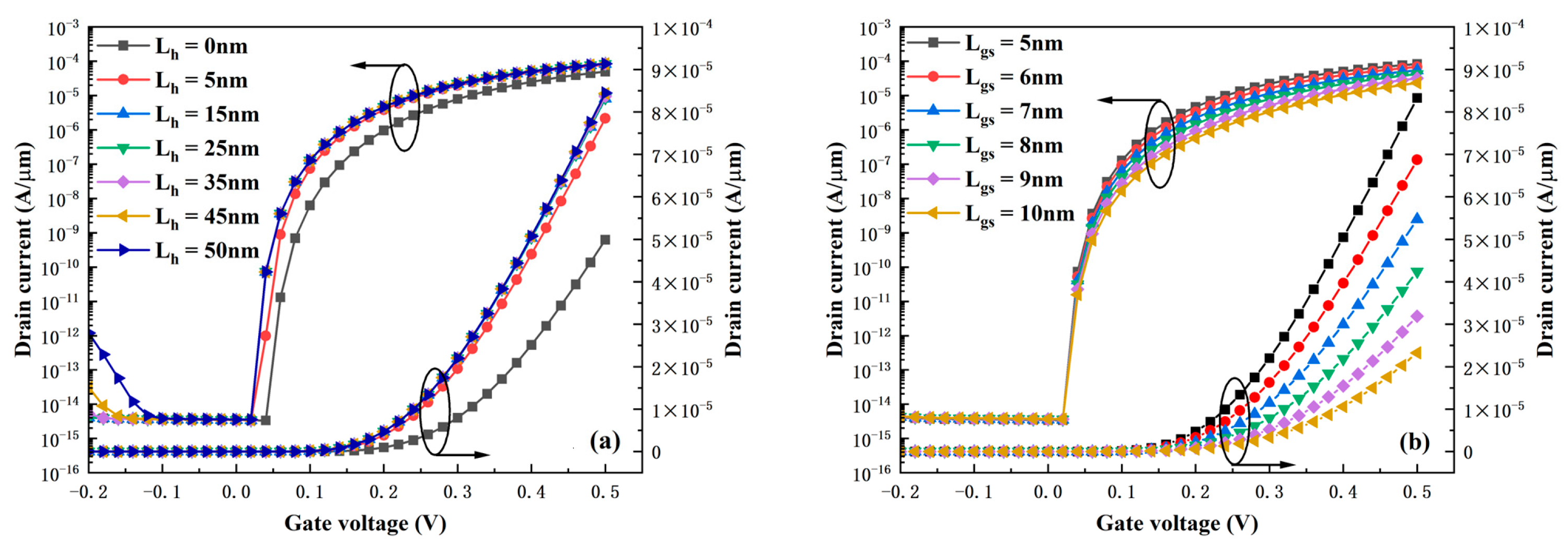
The transfer characteristics of the HDL-TFET as a function of a HfO2 gate dielectric length Lh are presented in Figure 7a. Similarly to the variation in the drain work function Wd, the device also exhibits robustness against changes in Lh. It can be clearly observed from Figure 7a that as long as the variation of Lh does not affect the vicinity of the tunneling junctions between the source and channel, and between the drain and channel (Lh = 0 nm, Lh = 50 nm), the device performance remains essentially unchanged. This significantly reduces the manufacturing difficulty and improves the device reliability. Figure 7b presents the variation in transfer characteristics of the HDL-TFET under different gate-source lengths Lgs. It can be clearly observed that the value of Lgs affects the device current under any positive voltage—with the increase of Lgs, the current decreases accordingly. In the on-state, the ION when Lgs = 10 nm decreases by 72% compared with that when Lgs = 5 nm. This phenomenon is easy to understand: as Lgs increases, the band buffer region between the source and the gate becomes larger, while the energy level of the band under the corresponding voltage remains unchanged. This makes the band variation gentler and leads to a significant increase in the effective tunneling length λ, thereby severely degrading the device current.
The results indicate that the HDL-TFET exhibits a certain degree of stability against most process fluctuations. However, the key drawback lies in the significant impact of process variations at the heterojunction, making the process parameters at the heterojunction a critical focus during device fabrication.

3.3. Heterogate Dielectric Engineering

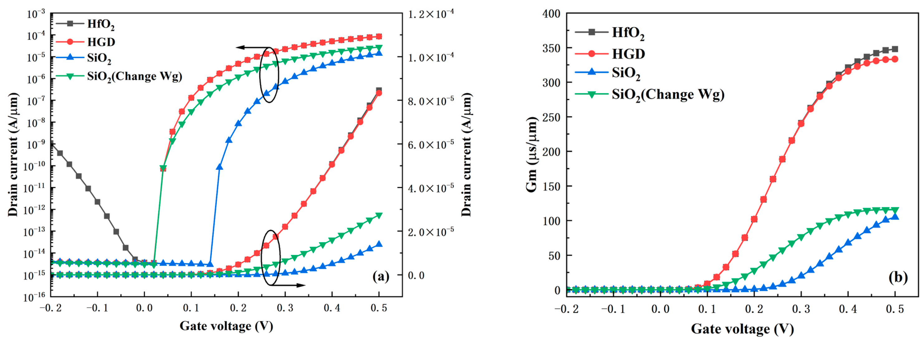
An important feature of the HDL-TFET is the adoption of a heterogate dielectric (HGD) structure. This structure not only enhances the device’s DC performance but is also crucial for reducing parasitic capacitance, thereby greatly improving the device’s application value in high-frequency circuits. The primary advantage of the HGD structure lies in its ability to integrate the merits of different gate dielectrics for the independent optimization of each region, which is different from the stacked gate dielectric structure studied in Reference [28]. The stacked gate dielectric structure optimizes the device as a whole; the improvement in on-state performance means the degradation in off-state performance. Thus, the HGD structure is more conducive to the comprehensive enhancement of device performance. Figure 8a presents the transfer characteristics when the gate dielectric is HfO2, HGD, and SiO2, respectively. For the fairness of comparison, the transfer characteristic curve of the SiO2 gate dielectric device—with its tunneling turn-on voltage adjusted to be consistent with other cases by modifying the gate work function Wg—is also plotted in Figure 8a. It can be observed that the HGD device inherits the low IOFF of the SiO2 device and the high ION of the HfO2 device. Compared with the SiO2 device with adjusted Wg, the ION increases from 2.75 × 10⁻⁵ A/μm to 8.33 × 10⁻⁵ A/μm. Compared with the HfO2 device, the ambipolar current decreases from 1.1 × 10⁻⁹ A/μm to 4.1 × 10⁻¹⁵ A/μm, a reduction of 6 orders of magnitude. Figure 8b shows the comparison of transconductance Gm under different gate dielectrics. Gm is defined as shown in Equation (3) and measures the device’s amplification capability. The results indicate that the Gm of the HGD structure is much larger than that of the SiO2 structure and basically consistent with that of the HfO2 structure. This endows the device with excellent amplification capability, which usually enables higher gain in circuit applications.
G m = d I d s / d V g s
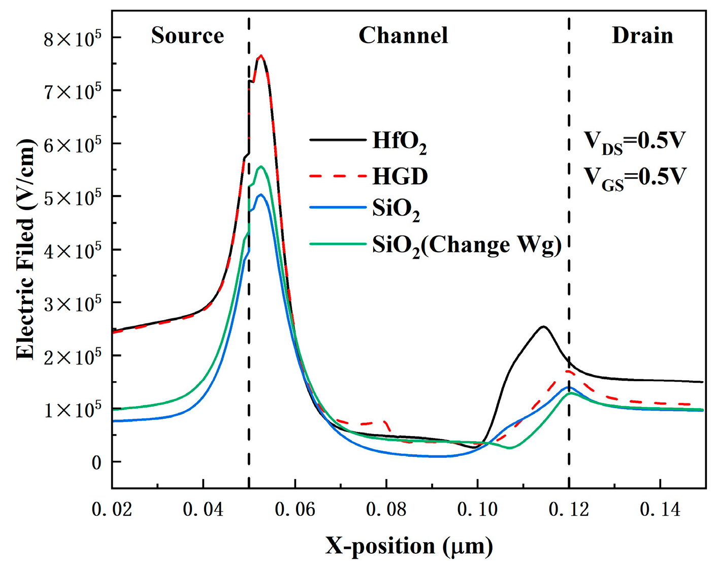
The main reason for the performance improvement of the HGD structure lies in the variation in the electric field caused by the difference in dielectric constants between HfO2 and SiO2. Figure 9 presents the electric field distributions at 1 nm beneath the gate dielectric in the on-state for different device structures, which reveals the underlying mechanism responsible for the variations in the transfer curves shown in Figure 8a. At the gate-source region, the HGD structure and the HfO2 structure exhibit the strongest electric field, which significantly enhances ION. In contrast, at the gate-drain region, the electric field of the HGD structure is lower than that of the HfO2 structure due to the low dielectric constant of SiO2—and this is the origin of the low leakage current. Additionally, the optimization of parasitic capacitance by the HGD structure is closely related to the electric field distribution shown in Figure 9.
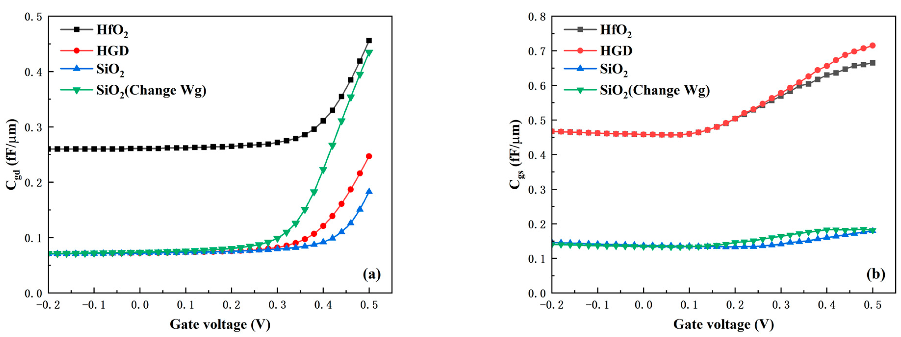
The optimization of parasitic capacitance by the HGD structure is demonstrated in Figure 10a,b. Figure 10a,b present the variations in gate-drain capacitance Cgd and gate-source capacitance Cgs under different gate dielectrics, respectively. It can be clearly observed that the Cgd of the HGD device is at the same level as that of the SiO2 device. Compared with the Cgd of the HfO2 device in the on-state, the HGD device’s Cgd decreases by 46%. However, the Cgs of the HGD device is at the same level as that of the HfO2 device and higher than that of the SiO2 device. This observation is consistent with the electric field distribution illustrated in Figure 9. Since Cgd depends on the electric field near the gate-drain region and Cgs is dependent on the electric field near the gate-source region, the HGD structure effectively reduces Cgd while causing no significant change in Cgs. Even so, the maximum value of Cgs is only 0.71 fF. This Cgs value is completely acceptable given the device’s excellent DC performance and extremely low Cgd. The HGD structure enables the device to have both high Gm and low parasitic capacitance, endowing it with excellent RF characteristics and high potential for high-frequency applications.

3.4. Optimization of the Dual-Electrode Structure

Figure 11 shows the HDL-TFET with a single-electrode structure (SE). Compared with the dual-electrode structured HDL-TFET (DE) proposed in this work, the SE structure can further simplify the fabrication process—it only requires depositing electrode metals via ALD technology. Although the DE structure increases process complexity compared with the SE structure, its improvement in device performance is noteworthy.
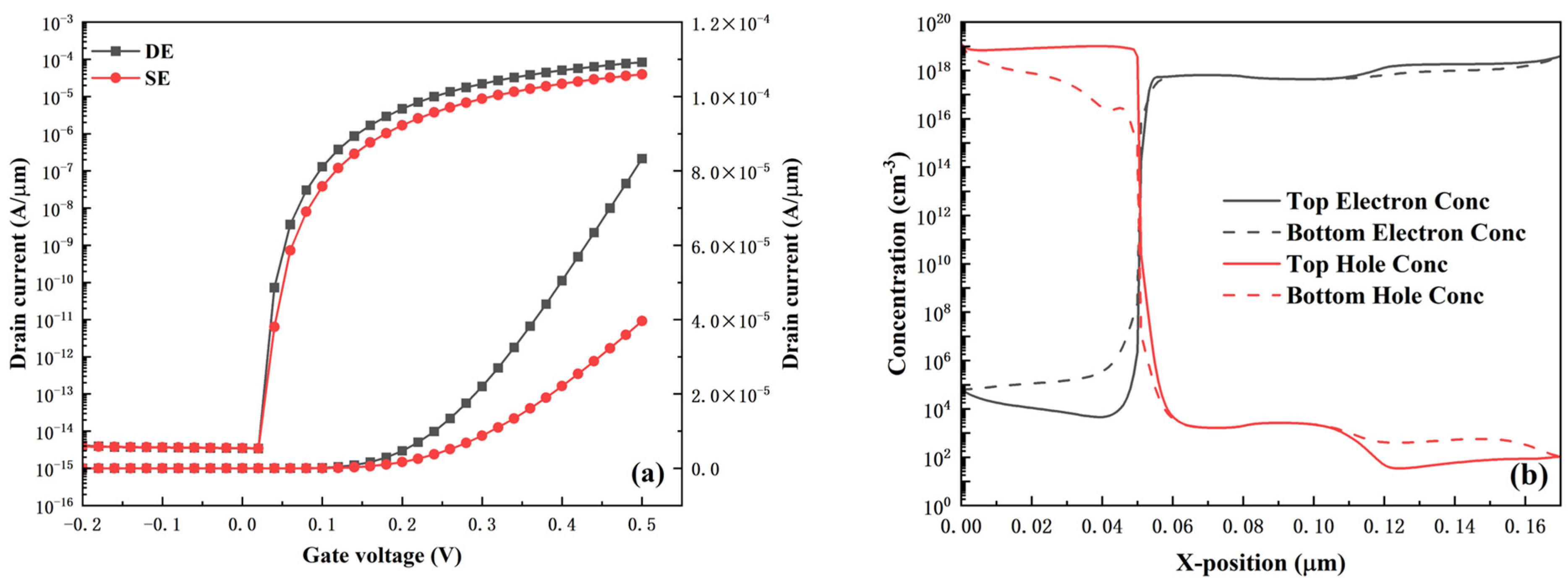
As shown in Figure 12, the performance enhancement of the DE structure over the SE structure, in terms of DC characteristics, mainly focuses on the subthreshold swing and on-state current. The SE structure exhibits an SSavg of 13 mV/dec and an ION of 3.96 × 10⁻⁵ A/μm, which are 28% and 52% worse than those of the DE structure, respectively. Figure 12b illustrates the degradation mechanism of the SE structure: the carrier distribution induced near the top gate and bottom gate of the SE structure is inconsistent. The SE structure has no source-drain electrodes at the bottom, and the bulk material near the bottom gate is relatively far from the top electrode. This reduces the concentration of carriers induced in the bulk material near the bottom gate, ultimately degrading carrier tunneling around the bottom gate. However, as observed in Figure 3c, the electron tunneling rate distribution of the DE structure exhibits symmetry between the top gate and the bottom gate. The enhanced carrier tunneling near the bottom gate further optimizes the device performance. This is also reflected in the optimization of the device’s RF performance presented in Figure 13.
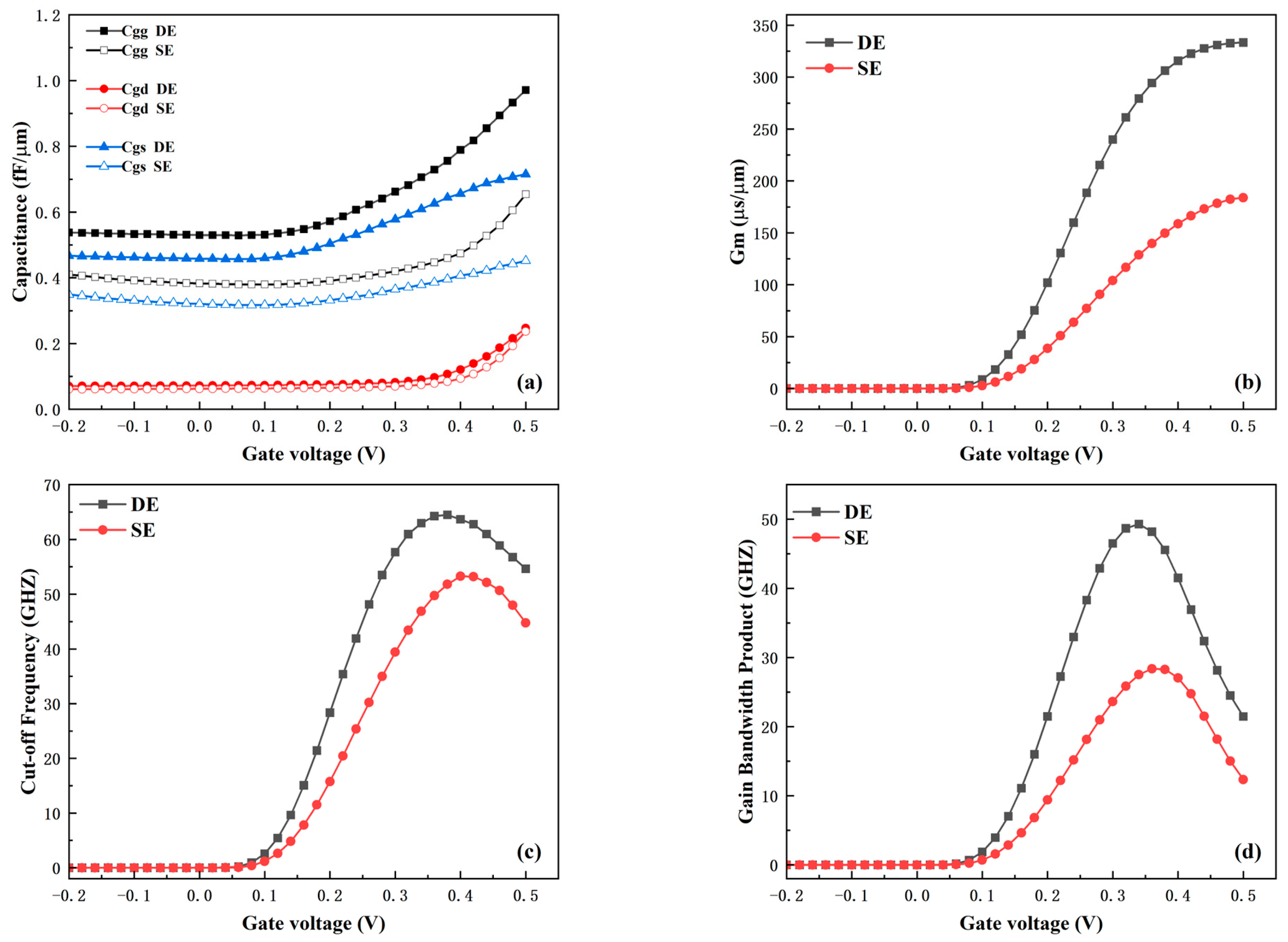
The RF characteristics of the device are crucial parameters for integrated circuit applications. Figure 13 presents a comparison of the RF parameters between the two electrode structures under a 1 MHz AC signal. Figure 13a shows the parasitic capacitance characteristics of the DE and SE structures. The results indicate that the DE structure has relatively larger parasitic capacitance, mainly because the introduction of the bottom source-drain electrodes increases the parasitic capacitance between the gate and drain, as well as between the gate and source. Although the parasitic capacitance performance of the DE structure is slightly degraded, the RF performance of the device requires a comprehensive evaluation. Figure 13b–d show the comparisons of transconductance (Gm), cut-off frequency (fT), and gain-bandwidth product (GBP) between the two structures. These three parameters are calculated using Equations (3)–(5) [29].
f T = G m / 2 π C g g
G B P = G m / 2 π 10 C g d
Gm measures the amplification capability of the device; thus, the higher gain in circuit applications necessarily requires a larger Gm. As shown in Figure 13b, benefiting from the optimization of the DE structure, the Gm of the DE device is significantly higher than that of the SE structure. The peak value of Gm reaches 333 μS/μm, which is an 81% improvement compared with the SE structure. According to Equations (4) and (5), fT and GBP are proportional to Gm and inversely proportional to parasitic capacitance. Since the improvement in Gm brought by the DE structure is far greater than the degradation of parasitic capacitance, it can be observed from Figure 13c,d that the DE structure achieves higher fT and GBP. The peak value of fT is 64 GHz, which is a 21% increase compared with the SE structure; the peak value of GBP is 49 GHz, representing a 75% improvement over the SE structure. In summary, the introduction of the DE structure significantly enhances the DC and RF performance of the device.
To further demonstrate the advantages of the work presented in this paper, Table 2 summarizes the performance comparison between this work and other studies reported in the literature.

4. Conclusions

In this work, an In0.53Ga0.47As/GaAs0.51Sb0.49 heterojunction dopingless TFET with a heterogate dielectric is proposed and investigated, aiming to extend the advantages of dopingless TFET in low-power applications. Benefiting from the superiority of the quasi-broken gap energy band of the In0.53Ga0.47As/GaAs0.51Sb0.49 heterojunction, the HDL-TFET achieves extremely high BTBT efficiency. To further enhance the device’s DC and RF performance, a heterogate dielectric structure and a dual-electrode structure are introduced. Under the combined effect of these advantages, the HDL-TFET operates at a low voltage of 0.5 V, delivering a high ION of up to 8.33 × 10⁻⁵ A/μm and a steep average subthreshold swing of 10.18 mV/dec. Meanwhile, thanks to the HGD structure and low drain work function, off-state tunneling of the HDL-TFET is further suppressed, resulting in an ultra-low IOFF of 3.42 × 10⁻¹⁵ A/μm and a high ION/IOFF of 2.44 × 10¹⁰, with no obvious ambipolar current. In addition, a comprehensive evaluation of the performance improvements brought by the HGD and DE structures is also conducted based on DC and RF characteristics. The results demonstrate that the introduction of these two structures significantly enhances the device’s DC and RF performance. Compared with other reported works in the literature, the proposed HDL-TFET exhibits distinct advantages. The research in this paper will lay the foundation for practical experiments on subsequent devices. The main limitation of the HDL-TFET lies in device fabrication, as the nanoscale process flow poses considerable challenges. However, with the advancement of nanotechnology, the HDL-TFET, leveraging the advantage of a dopingless structure, will exhibit tremendous potential in low-power circuit applications.

Author Contributions

Conceptualization, J.H.; Methodology, J.H.; Validation, J.H.; Formal analysis, J.H. and C.C.; Investigation, J.H. and S.C.; Writing—original draft, J.H.; Writing—review and editing, S.C., S.W., and C.L.; Supervision, H.L.; Project administration, H.L.; Funding acquisition, H.L. All authors have read and agreed to the published version of the manuscript.

Funding

This research was funded by the National Natural Science Foundation of China, grant number U2241221, and the Opening Project of Science and Technology on Reliability Physics and Application Technology of Electronic Component Laboratory, grant number ZHD202301.

Data Availability Statement

The original contributions presented in the study are included in the article; further inquiries can be directed to the corresponding author.

Conflicts of Interest

The authors declare no conflicts of interest.

References

  1. Ahn, D.-H.; Yoon, S.-H.; Kato, K.; Fukui, T. Takenaka and S. Takagi. Effects of ZrO2/Al2O3 Gate-Stack on the Performance of Planar-Type InGaAs TFET. IEEE Trans. Electron Devices 2019, 66, 1862–1867. [Google Scholar] [CrossRef]
  2. Kim, J.H.; Kim, S.; Park, B.-G. Double-Gate TFET with Vertical Channel Sandwiched by Lightly Doped Si. IEEE Trans. Electron Devices 2019, 66, 1656–1661. [Google Scholar] [CrossRef]
  3. Seabaugh, A.C.; Zhang, Q. Low-Voltage Tunnel Transistors for Beyond CMOS Logic. Proc. IEEE 2010, 98, 2095–2110. [Google Scholar] [CrossRef]
  4. Dash, S.; Sahoo, G.S.; Mishra, G.P. Subthreshold swing minimization of cylindrical tunnel FET using binary metal alloy gate. Superlattices Microstruct. 2016, 91, 105–111. [Google Scholar] [CrossRef]
  5. Maurya, A.; Koley, K.; Mech, B.C.; Kumar, J.; Kumar, P. Investigation of Source Region’s Random Doping Fluctuation Effects on Analog and RF Performance in All-Si DG-TFET. IEEE Trans. Electron Devices 2022, 69, 5330–5336. [Google Scholar] [CrossRef]
  6. Damrongplasit, N.; Kim, S.H.; Liu, T.-J.K. Study of Random Dopant Fluctuation Induced Variability in the Raised-Ge-Source TFET. IEEE Electron Device Lett. 2013, 34, 184–186. [Google Scholar] [CrossRef]
  7. Kumar, M.J.; Janardhanan, S. Doping-Less Tunnel Field Effect Transistor: Design and Investigation. IEEE Trans. Electron Devices 2013, 60, 3285–3290. [Google Scholar] [CrossRef]
  8. Ashok, T.; Pandey, C.K. Demonstration of a novel Dual-Source Elevated-Channel Dopingless TFET with improved DC and Analog/RF performance. Microelectron. J. 2024, 144, 106071. [Google Scholar] [CrossRef]
  9. Sharma, S.; Basu, R.; Kaur, B. Temperature Analysis of a Dopingless TFET Considering Interface Trap Charges for Enhanced Reliability. IEEE Trans. Electron Devices 2022, 69, 2692–2697. [Google Scholar] [CrossRef]
  10. Gupta, A.K.; Raman, A. Performance analysis of electrostatic plasma-based dopingless nanotube TFET. Appl. Phys. A 2020, 126, 573. [Google Scholar] [CrossRef]
  11. Duan, X.; Zhang, J.; Wang, S.; Li, Y.; Xu, S.; Hao, Y. A High-Performance Gate Engineered InGaN Dopingless Tunnel FET. IEEE Trans. Electron Devices 2018, 65, 1223–1229. [Google Scholar] [CrossRef]
  12. Choudhary, V.; Agrawal, S.; Kumar, M.; Verma, M. Negative Capacitance Vertical Dopingless TFET and Its Analog/RF Analysis Using Interface Trap Charges. IEEE Trans. Device Mater. Reliab. 2025, 25, 163–172. [Google Scholar] [CrossRef]
  13. Hueting, R.J.E.; Rajasekharan, B.; Salm, C.; Schmitz, J. The Charge Plasma P-N Diode. IEEE Electron Device Lett. 2008, 29, 1367–1369. [Google Scholar] [CrossRef]
  14. Tripathy, M.R.; Singh, A.K.; Baral, K.; Singh, P.K.; Jit, S. III-V/Si staggered heterojunction based source-pocket engineered vertical TFETs for low power applications. Superlattices Microstruct. 2020, 142, 106494. [Google Scholar] [CrossRef]
  15. Shaker, A.; Maged, A.; Elshorbagy, A.; AbouElainain, A.; Elsabbagh, M. Source-all-around tunnel field-effect transistor (SAA-TFET): Proposal and design. Semicond. Sci. Technol. 2020, 35, 025007. [Google Scholar] [CrossRef]
  16. Zhao, H.; Chen, Y.; Wang, Y.; Zhou, F.; Xue, F.; Lee, J. In0.7Ga0.3As Tunneling Field-Effect Transistors with an Ion of 50 μA/μm and a Subthreshold Swing of 86 mV/dec Using HfO2 Gate Oxide. IEEE Electron Device Lett. 2010, 31, 1392–1394. [Google Scholar] [CrossRef]
  17. Zhao, H.; Chen, Y.-T.; Wang, Y.; Zhou, F.; Xue, F.; Lee, J.C. Improving the on-current of In0.7Ga0.3As tunneling field-effect-transistors by p++/n+ tunneling junction. Appl. Phys. Lett. 2011, 98, 093501. [Google Scholar] [CrossRef]
  18. Lu, B.; Cui, Y.; Guo, A.; Wang, D.; Lv, Z.; Zhou, J.; Miao, Y. Characteristics of InAs/GaSb Line-Tunneling FETs with Buried Drain Technique. IEEE Trans. Electron Devices 2021, 68, 1537–1541. [Google Scholar] [CrossRef]
  19. Sharma, A.; Akkala, A.G.; Kulkarni, J.P.; Roy, K. Source-Underlapped GaSb–InAs TFETs with Applications to Gain Cell Embedded DRAMs. IEEE Trans. Electron Devices 2016, 63, 2563–2569. [Google Scholar] [CrossRef]
  20. Long, P.; Wilson, E.; Huang, J.Z.; Klimeck, G.; Rodwell, M.J.W.; Povolotskyi, M. Design and Simulation of GaSb/InAs 2D Transmission-Enhanced Tunneling FETs. IEEE Electron Device Lett. 2016, 37, 107–110. [Google Scholar] [CrossRef]
  21. Yu, T.-Y.; Peng, L.-S.; Lin, C.-W.; Hsin, Y.-M. GaAsSb/InGaAs tunnel field effect transistor with a pocket layer. Microelectron. Reliab. 2018, 83, 235–237. [Google Scholar] [CrossRef]
  22. Shih, P.-C.; Hou, W.-C.; Li, J.-Y. A U-Gate InGaAs/GaAsSb Heterojunction TFET of Tunneling Normal to the Gate with Separate Control Over ON- and OFF-State Current. IEEE Electron Device Lett. 2017, 38, 1751–1754. [Google Scholar] [CrossRef]
  23. Liu, H.; Yang, L.-A.; Jin, Z.; Hao, Y. An In0.53Ga0.47As/In0.52Al0.48As Heterojunction Dopingless Tunnel FET with a Heterogate Dielectric for High Performance. IEEE Trans. Electron Devices 2019, 66, 3229–3235. [Google Scholar] [CrossRef]
  24. Keighobadi, D.; Mohammadi, S.; Mohtaram, M. Switching Performance Investigation of a Gate-All-Around Core-Source InGaAs/InP TFET. Trans. Electr. Electron. Mater. 2021, 22, 502–508. [Google Scholar] [CrossRef]
  25. Bhattacharyya, A.; Chanda, M.; De, D. GaAs0.5Sb0.5/In0.53Ga0.47As heterojunction dopingless charge plasma-based tunnel FET for analog/digital performance improvement. Superlattices Microstruct. 2020, 142, 106522. [Google Scholar] [CrossRef]
  26. Gotow, T.; Mitsuhara, M.; Hoshi, T.; Sugiyama, H.; Takenaka, M.; Takagi, S. Effects of impurity and composition profiles on electrical characteristics of GaAsSb/InGaAs hetero-junction vertical tunnel field effect transistors. J. Appl. Phys. 2017, 122, 174503. [Google Scholar] [CrossRef]
  27. Chen, S.; Wang, S.; Liu, H.; Han, T.; Xie, H.; Chong, C. A Novel Dopingless Fin-Shaped SiGe Channel TFET with Improved Performance. Nanoscale Res. Lett. 2020, 15, 202. [Google Scholar] [CrossRef]
  28. Mehrad, S.; Yaghobi, H.; Eyvazi, K.; Karami, M.A. Gate Dielectric Engineering Using Stacked Gate Dielectric in U-Shaped Gate Tunnel FET. IET Circuits Devices Syst. 2025, 11, 5014133. [Google Scholar] [CrossRef]
  29. Xie, H.; Liu, H.; Chen, S.; Han, T.; Wang, S. Electrical performance of InAs/GaAs0.1Sb0.9 heterostructure junctionless TFET with dual-material gate and Gaussian-doped source. Semicond. Sci. Technol. 2020, 35, 095004. [Google Scholar] [CrossRef]
  30. Apoorva; Kumar, N.; Amin, S.I.; Anand, S. Design and Performance Optimization of Novel Core–Shell Dopingless GAA-Nanotube TFET with Si0.5Ge0.5-Based Source. IEEE Trans. Electron Devices 2020, 67, 789–795. [Google Scholar] [CrossRef]
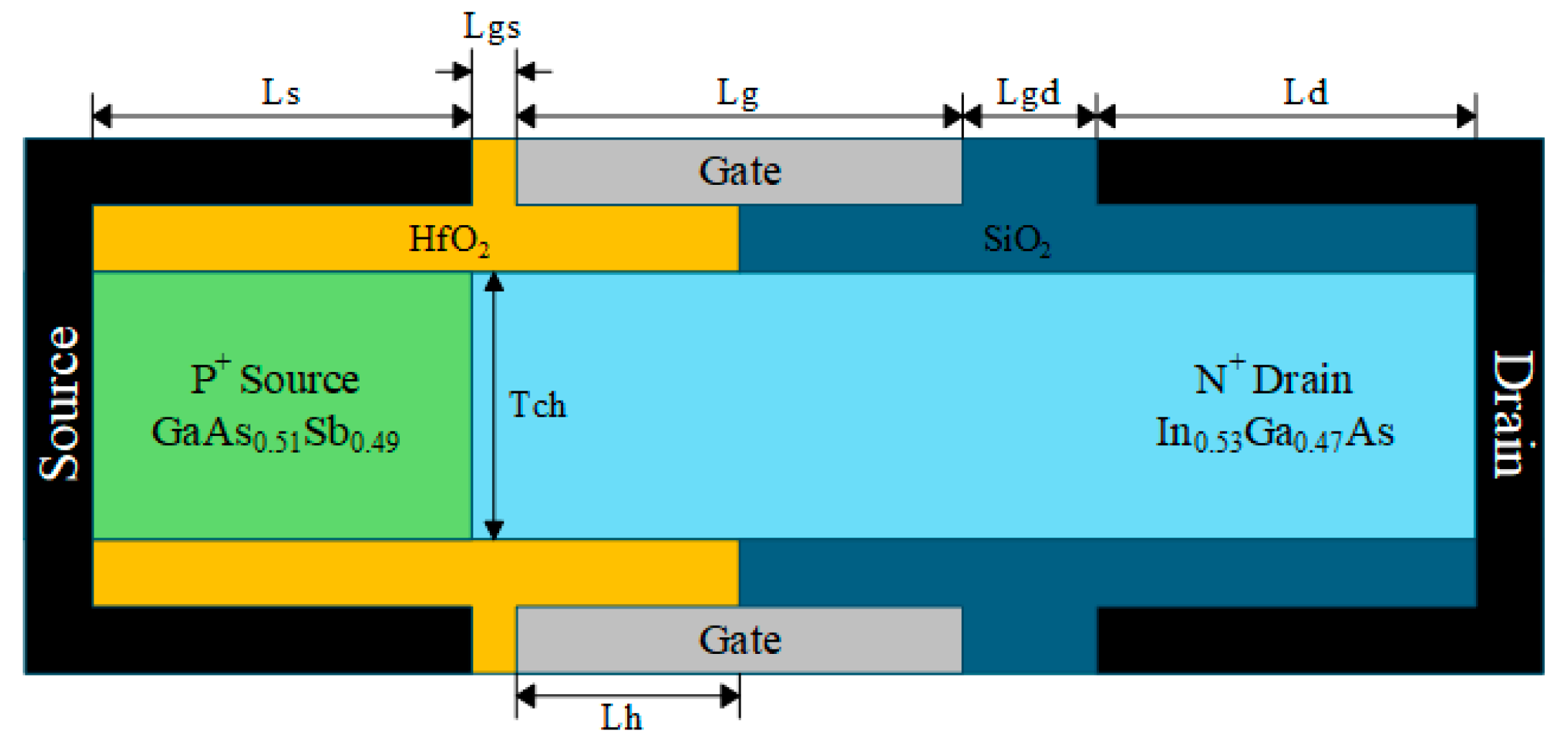
Figure 1. HDL-TFET device structure.
Micromachines 16 01330 g001
Figure 2. HDL-TFET fabrication process (a) epitaxial growth. (b) ICP etching. (c) SiO2 Deposition. (d) Etch SiO2 and deposit the gate electrode. (e) HfO2 Deposition (f) Form the source and drain electrodes.
Micromachines 16 01330 g002
Figure 3. (a) Energy band diagram at 1 nm below the gate dielectric. (b) Electric field distribution in the on-state. (c) Electron tunneling rate distribution in the on-state.
Micromachines 16 01330 g003
Figure 4. (a) Transfer characteristic, (b) output characteristic.
Micromachines 16 01330 g004
Figure 5. (a) Transfer characteristics under different source work functions. (b) On-state energy band diagrams under different source work functions.
Micromachines 16 01330 g005
Figure 6. (a) Transfer characteristics under different drain work functions. (b) ION and IOFF under different drain work functions.
Micromachines 16 01330 g006
Figure 7. (a) Transfer characteristics under different HfO2 gate dielectric lengths Lh. (b) Transfer characteristics under different gate-source length Lgs.
Micromachines 16 01330 g007
Figure 8. (a) Transfer characteristics and (b) transconductance Gm under different gate dielectrics.
Micromachines 16 01330 g008
Figure 9. Electric field distributions at 1 nm beneath the gate dielectric in the on-state for different device structures.
Micromachines 16 01330 g009
Figure 10. (a) Gate-drain capacitance Cgd and (b) gate-source capacitance Cgs under different gate dielectrics.
Micromachines 16 01330 g010
Figure 11. HDL-TFET with a single-electrode structure.
Micromachines 16 01330 g011
Figure 12. (a) Comparison of transfer characteristics between DE and SE structures. (b) Electron and hole concentration distributions at the top and bottom of the SE structure.
Micromachines 16 01330 g012
Figure 13. Comparisons of (a) parasitic capacitance, (b) transconductance Gm, (c) cut-off frequency fT, and (d) gain bandwidth product GBP between DE and SE structures.
Micromachines 16 01330 g013
Table 1. Main parameters of HDL-TFET.
Parameter NameSymbolValue
Oxide thicknessTox2 nm
Channel thicknessTch10 nm
Source lengthLs50 nm
Gate lengthLg50 nm
Drain lengthLd50 nm
HfO2 gate dielectric lengthLh25 nm
Gate-source lengthLgs5 nm
Gate-drain lengthLgd15 nm
Gate work functionWg4.7 eV
Drain work functionWd4.4 eV
Source work functionWs5.0 eV
Table 2. Performance comparison between this work and other studies reported in the literature.
ION (A/μm)ION/IOFF S S a v g fT (GHz)GBP (GHz)
This work (VGS = 0.5 V)8.33 × 10−52.44 × 101010.186449
Ref. [7] (VGS = 1.5 V)1.1 × 10−51.1 × 1012100--
Ref. [8] (VGS = 2.0 V)1.36 × 10−61.47 × 1011910.310.33
Ref. [21] (VGS = 0.5 V)1.2 × 10⁻⁵-227--
Ref. [23] (VGS = 0.6 V)1.67 × 10−51.96 × 10836.6135.23
Ref. [25] (VGS = 0.6 V)4.05 × 10−54.86 × 10920.37112
Ref. [27] (VGS = 1.0 V)5.88 × 10−55.88 × 101218.25.041.29
Ref. [30] (VGS = 1.0 V)1.69 × 10−58.46 × 101131.3836-
Disclaimer/Publisher’s Note: The statements, opinions and data contained in all publications are solely those of the individual author(s) and contributor(s) and not of MDPI and/or the editor(s). MDPI and/or the editor(s) disclaim responsibility for any injury to people or property resulting from any ideas, methods, instructions or products referred to in the content.