Fabrication, Experiments, and Analysis of an LBM Additive-Manufactured Flexure Parallel Mechanism


Abstract
1. Introduction
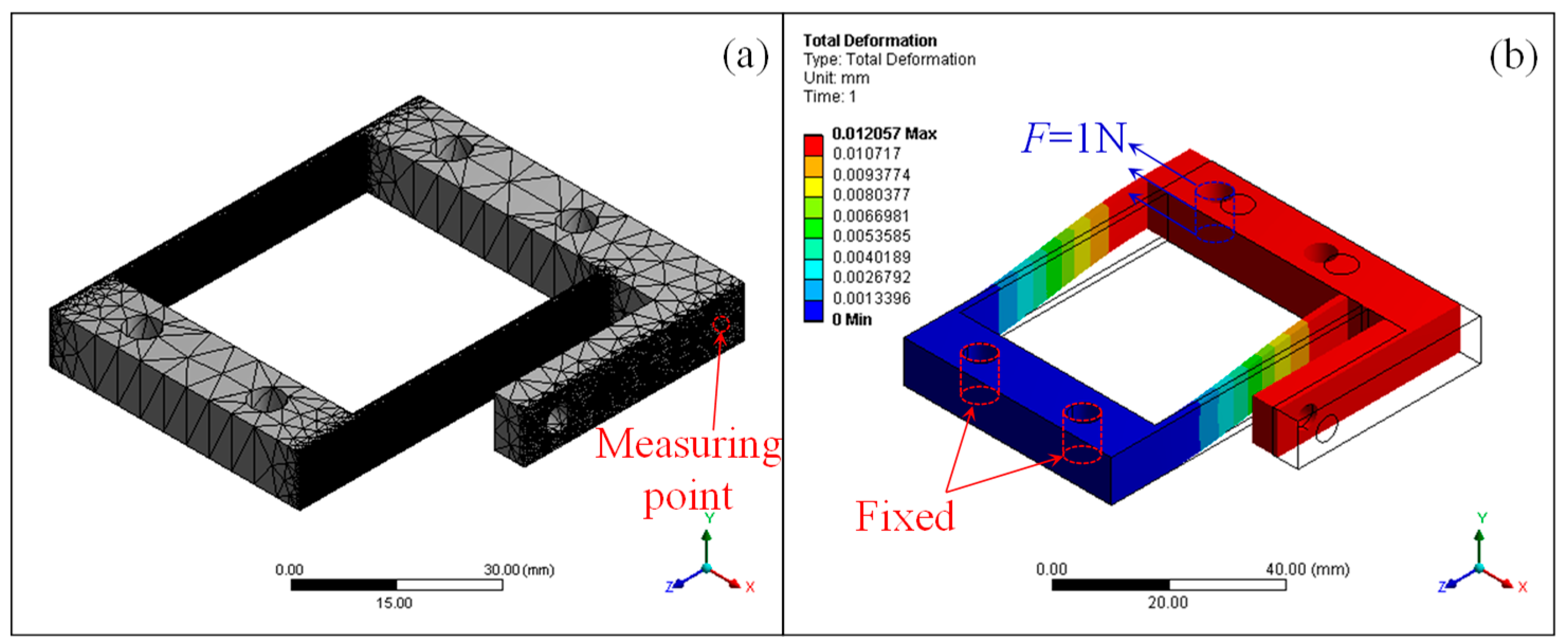
- (a).
- (b).
- The LBM process has a large range of building materials [26]. 316L has been widely investigated and utilized for research and engineering. The cost of fabricating 316L parts through LBM is competitive compared with that of traditional manufacturing, especially for small batch sizes.
2. Materials and Methods
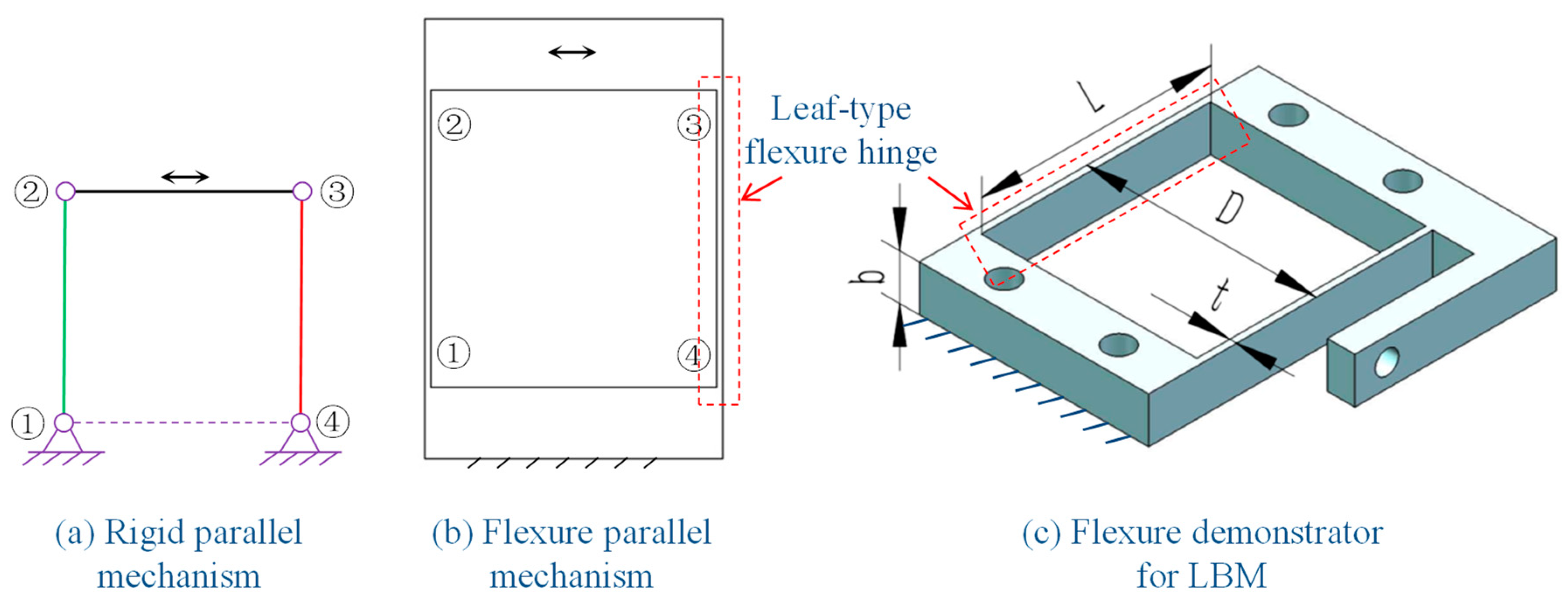
2.1. Flexure Parallel Mechanism
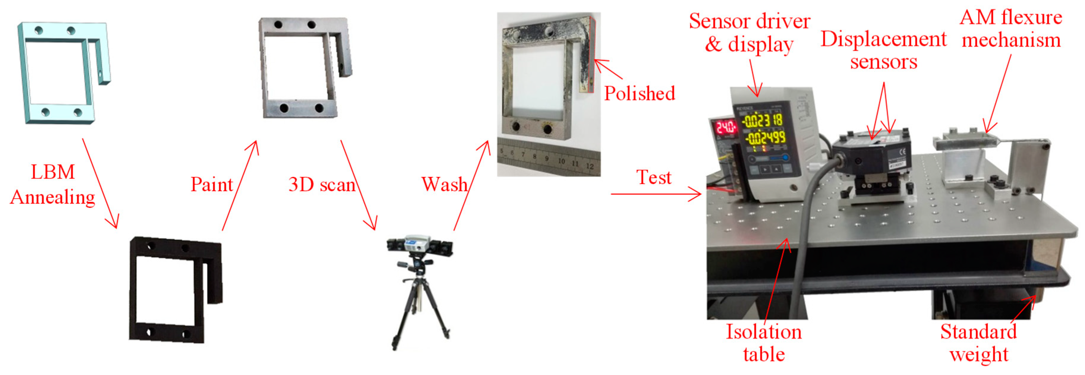
2.2. Fabrication, Measurement, and Experiments
3. Results
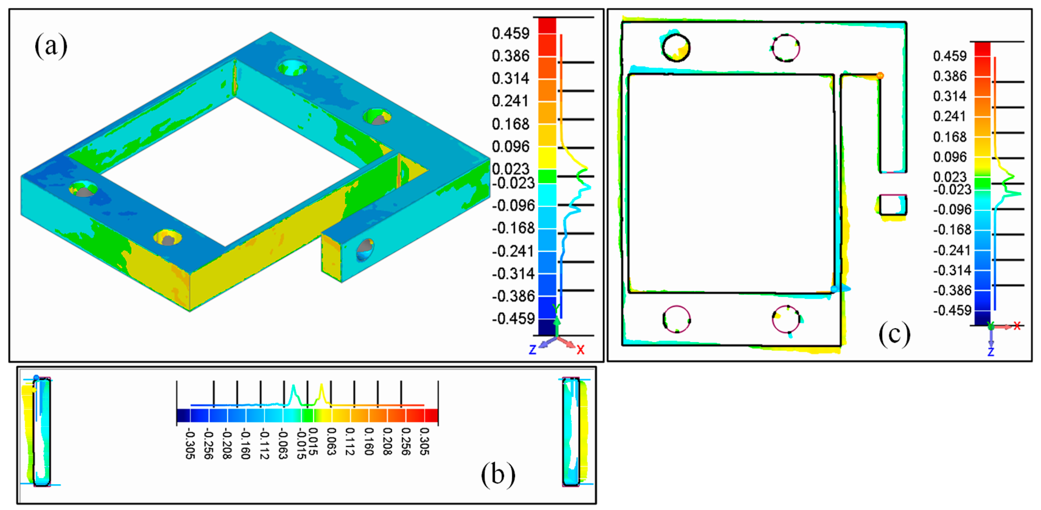
3.1. Analysis of Geometrical Measurements
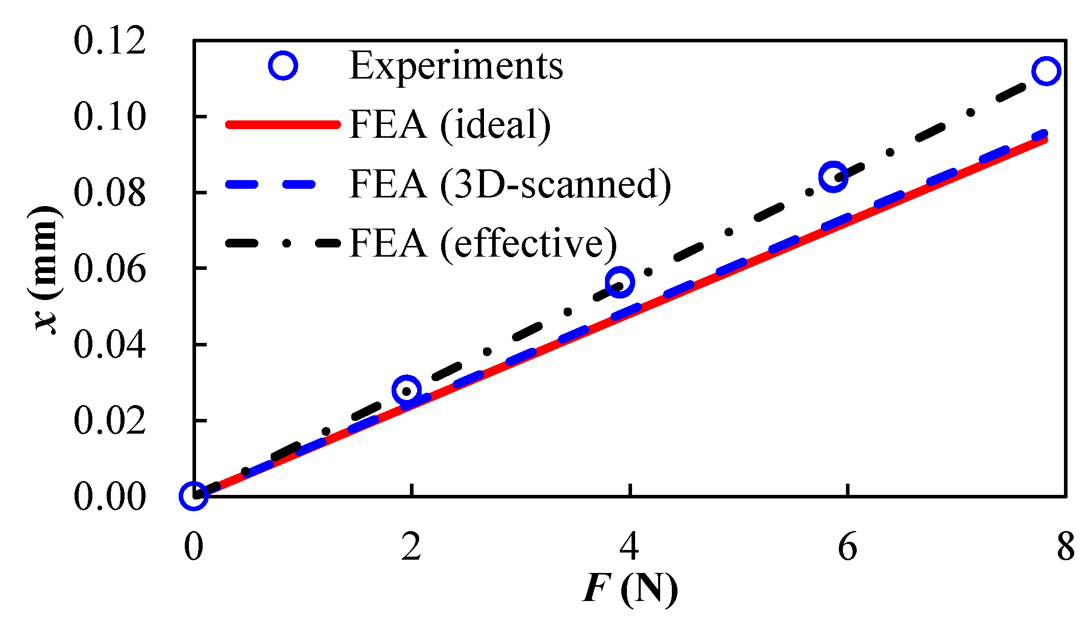
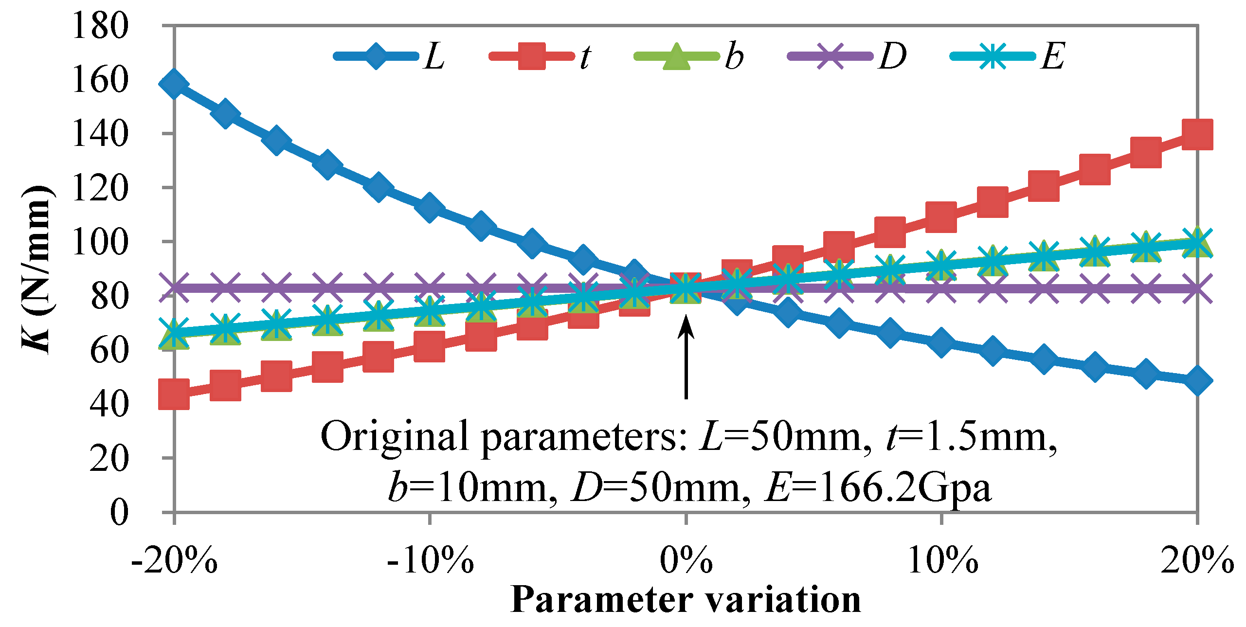
3.2. Analysis of Stiffness Experiments
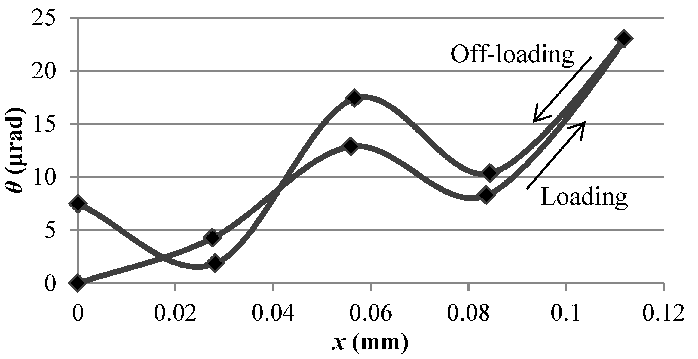
3.3. Analysis of Motion Accuracy
4. Discussion
5. Conclusions
Author Contributions
Funding
Acknowledgments
Conflicts of Interest
References
- Li, Y.; Xu, Q. Design and robust repetitive control of a new parallel-kinematic XY piezostage for micro/nanomanipulation. IEEE/ASME Trans. Mechatron. 2012, 17, 1120–1132. [Google Scholar] [CrossRef]
- Yu, J.; Xie, Y.; Li, Z.; Hao, G. Design and experimental testing of an improved large-range decoupled XY compliant parallel micromanipulator. J. Mech. Robot. 2015, 7, 044503. [Google Scholar] [CrossRef]
- Wei, H.; Shirinzadeh, B.; Li, W.; Clark, L.; Pinskier, J.; Wang, Y. Development of piezo-driven compliant bridge mechanisms: general analytical equations and optimization of displacement amplification. Micromachines 2017, 8, 238. [Google Scholar] [CrossRef]
- Qin, Y.; Shirinzadeh, B.; Tian, Y.; Zhang, D.; Bhagat, U. Design and computational optimization of a decoupled 2-DOF monolithic mechanism. IEEE/ASME Trans. Mechatron. 2014, 19, 872–881. [Google Scholar] [CrossRef]
- Yong, Y.K.; Moheimani, S.R.; Kenton, B.J.; Leang, K.K. Invited review article: High-speed flexure-guided nanopositioning: Mechanical design and control issues. Rev. Sci. Instrum. 2012, 83, 121101. [Google Scholar] [CrossRef] [PubMed]
- Lobontiu, N. Compliant Mechanisms: Design of Flexure Hinges; CRC Press: Boca Raton, FL, USA, 2002. [Google Scholar]
- Hao, G. Design and analysis of symmetric and compact 2R1T (in-plane 3-DOC) flexure parallel mechanisms. Mech. Sci. 2017, 8, 1–9. [Google Scholar] [CrossRef]
- Wei, H.X.; Wei, L.; Yang, X.F.; Wang, Y.Q.; Wang, C.T. Static analysis and optimal design of θxθyZ micropositioner with planar compliant mechanisms. Robot 2016, 38, 557–562. [Google Scholar] [CrossRef]
- Hayes, G.R.; Frecker, M.I.; Adair, J.H. Fabrication of compliant mechanisms on the mesoscale. Mech. Sci. 2011, 2, 129–137. [Google Scholar] [CrossRef]
- Coemert, S.; Traeger, M.F.; Graf, E.C.; Lueth, T.C. Suitability evaluation of various manufacturing technologies for the development of surgical snake-like manipulators from metals based on flexure hinges. Procedia CIRP 2017, 65, 1–6. [Google Scholar] [CrossRef]
- Lee, C.; Tarbutton, J.A. Compliance and control characteristics of an additive manufactured-flexure stage. Rev. Sci. Instrum. 2015, 86, 045107. [Google Scholar] [CrossRef] [PubMed]
- Clark, L.; Shirinzadeh, B.; Tian, Y.; Yao, B. Development of a passive compliant mechanism for measurement of micro/nanoscale planar 3-DOF motions. IEEE/ASME Trans. Mechatron. 2016, 21, 1222–1232. [Google Scholar] [CrossRef]
- Clark, L.; Shirinzadeh, B.; Zhong, Y.; Tian, Y.; Zhang, D. Design and analysis of a compact flexure-based precision pure rotation stage without actuator redundancy. Mech. Mach. Theory 2016, 105, 129–144. [Google Scholar] [CrossRef]
- Merriam, E.G.; Jones, J.E.; Magleby, S.P.; Howell, L.L. Monolithic 2 DOF fully compliant space pointing mechanism. Mech. Sci. 2013, 4, 381–390. [Google Scholar] [CrossRef]
- Merriam, E.G.; Tolman, K.A.; Howell, L.L. Integration of advanced stiffness-reduction techniques demonstrated in a 3D-printable joint. Mech. Mach. Theory 2016, 105, 260–271. [Google Scholar] [CrossRef]
- Merriam, E.G.; Jones, J.E.; Howell, L.L. Design of 3D-printed titanium compliant mechanisms. In Proceedings of the 42nd Aerospace Mechanisms Sympsium, Huntsville, AL, USA, 14–16 May 2014. [Google Scholar]
- Pham, M.T.; Teo, T.J.; Yeo, S.H.; Wang, P.; Nai, M.L.S. A 3-D printed Ti-6Al-4V 3-DOF compliant parallel mechanism for high precision manipulation. IEEE/ASME Trans. Mechatron. 2017, 22, 2359–2368. [Google Scholar] [CrossRef]
- Fiaz, H.S.; Settle, C.R.; Hoshino, K. Metal additive manufacturing for microelectromechanical systems: Titanium alloy (Ti-6Al-4V)-based nanopositioning flexure fabricated by electron beam melting. Sens. Actuators A Phys. 2016, 249, 284–293. [Google Scholar] [CrossRef]
- Zhou, L.; Yuan, T.; Tang, J.; Li, L.; Mei, F.; Li, R. Texture evolution, phase transformation and mechanical properties of selective laser melted Ti-13Nb-13Zr. Mater. Charact. 2018, 145, 185–195. [Google Scholar] [CrossRef]
- Attar, H.; Ehtemam-Haghighi, S.; Kent, D.; Dargusch, M.S. Recent developments and opportunities in additive manufacturing of titanium-based matrix composites: A review. Int. J. Mach. Tools Manuf. 2018, 133, 85–102. [Google Scholar] [CrossRef]
- Attar, H.; Calin, M.; Zhang, L.C.; Scudino, S.; Eckert, J. Manufacture by selective laser melting and mechanical behavior of commercially pure titanium. Mater. Sci. Eng. A 2014, 593, 170–177. [Google Scholar] [CrossRef]
- Herzog, D.; Seyda, V.; Wycisk, E.; Emmelmann, C. Additive manufacturing of metals. Acta Mater. 2016, 117, 371–392. [Google Scholar] [CrossRef]
- Murr, L.E.; Gaytan, S.M.; Ramirez, D.A.; Martinez, E.; Hernandez, J.; Amato, K.N.; Shindo, P.W.; Medina, F.R.; Wicker, R.B. Metal fabrication by additive manufacturing using laser and electron beam melting technologies. J. Mater. Sci. Technol. 2012, 28, 1–14. [Google Scholar] [CrossRef]
- Weißmann, V.; Drescher, P.; Bader, R.; Seitz, H.; Hansmann, H.; Laufer, N. Comparison of single Ti6Al4V struts made using selective laser melting and electron beam melting subject to part orientation. Metals 2017, 7, 91. [Google Scholar] [CrossRef]
- Rafi, H.K.; Karthik, N.V.; Gong, H.; Starr, T.L.; Stucker, B.E. Microstructures and mechanical properties of Ti6Al4V parts fabricated by selective laser melting and electron beam melting. J. Mater. Eng. Perform. 2013, 22, 3872–3883. [Google Scholar] [CrossRef]
- Niu, X.; Singh, S.; Garg, A.; Singh, H.; Panda, B.; Peng, X.; Zhang, Q. Review of materials used in laser-aided additive manufacturing processes to produce metallic products. Front. Mech. Eng. 2018, 13, 1–17. [Google Scholar] [CrossRef]
- Gu, D.D.; Meiners, W.; Wissenbach, K.; Poprawe, R. Laser additive manufacturing of metallic components: materials, processes and mechanisms. Int. Mater. Rev. 2012, 57, 133–164. [Google Scholar] [CrossRef]
- Antonysamy, A.A.; Meyer, J.; Prangnell, P.B. Effect of build geometry on the β-grain structure and texture in additive manufacture of Ti6Al4V by selective electron beam melting. Mater. Charact. 2013, 84, 153–168. [Google Scholar] [CrossRef]


| Composition | Cr | Ni | Mn | Si | O | Cu | P | C | Fe |
|---|---|---|---|---|---|---|---|---|---|
| Weight | 17.6 | 12.4 | 1.26 | 0.49 | 0.056 | 0.19 | 0.01 | 0.018 | Balance |
© 2018 by the authors. Licensee MDPI, Basel, Switzerland. This article is an open access article distributed under the terms and conditions of the Creative Commons Attribution (CC BY) license (http://creativecommons.org/licenses/by/4.0/).
Share and Cite
Wei, H.; Wang, L.; Niu, X.; Zhang, J.; Simeone, A. Fabrication, Experiments, and Analysis of an LBM Additive-Manufactured Flexure Parallel Mechanism. Micromachines 2018, 9, 572. https://doi.org/10.3390/mi9110572
Wei H, Wang L, Niu X, Zhang J, Simeone A. Fabrication, Experiments, and Analysis of an LBM Additive-Manufactured Flexure Parallel Mechanism. Micromachines. 2018; 9(11):572. https://doi.org/10.3390/mi9110572
Chicago/Turabian StyleWei, Huaxian, Li Wang, Xiaodong Niu, Jian Zhang, and Alessandro Simeone. 2018. "Fabrication, Experiments, and Analysis of an LBM Additive-Manufactured Flexure Parallel Mechanism" Micromachines 9, no. 11: 572. https://doi.org/10.3390/mi9110572
APA StyleWei, H., Wang, L., Niu, X., Zhang, J., & Simeone, A. (2018). Fabrication, Experiments, and Analysis of an LBM Additive-Manufactured Flexure Parallel Mechanism. Micromachines, 9(11), 572. https://doi.org/10.3390/mi9110572