Article

A Temperature-Compensated Single-Crystal Silicon-on-Insulator (SOI) MEMS Oscillator with a CMOS Amplifier Chip

Department of Electrical Engineering & Computer Science, Case School of Engineering, Case Western Reserve University, Cleveland, OH 44106, USA
*
Authors to whom correspondence should be addressed.
Micromachines 2018, 9(11), 559; https://doi.org/10.3390/mi9110559
Submission received: 13 August 2018 / Revised: 15 September 2018 / Accepted: 18 September 2018 / Published: 29 October 2018
(This article belongs to the Special Issue Development of CMOS-MEMS/NEMS Devices)

Abstract

:
Self-sustained feedback oscillators referenced to MEMS/NEMS resonators have the potential for a wide range of applications in timing and sensing systems. In this paper, we describe a real-time temperature compensation approach to improving the long-term stability of such MEMS-referenced oscillators. This approach is implemented on a ~26.8 kHz self-sustained MEMS oscillator that integrates the fundamental in-plane mode resonance of a single-crystal silicon-on-insulator (SOI) resonator with a programmable and reconfigurable single-chip CMOS sustaining amplifier. Temperature compensation using a linear equation fit and look-up table (LUT) is used to obtain the near-zero closed-loop temperature coefficient of frequency (TCf) at around room temperature (~25 °C). When subject to small temperature fluctuations in an indoor environment, the temperature-compensated oscillator shows a >2-fold improvement in Allan deviation over the uncompensated counterpart on relatively long time scales (averaging time τ > 10,000 s), as well as overall enhanced stability throughout the averaging time range from τ = 1 to 20,000 s. The proposed temperature compensation algorithm has low computational complexity and memory requirement, making it suitable for implementation on energy-constrained platforms such as Internet of Things (IoT) sensor nodes.

1. Introduction

Stable oscillators are vital for precision timekeeping in various applications, including wired and wireless communications, positioning, navigation, and sensing. In particular, oscillator stability against temperature variations and fluctuations is critical for many of these applications [1,2]. Temperature-compensated quartz crystal oscillators provide excellent stability versus temperature, and have thus dominated the timing and frequency control market for decades. However, they are not suitable for monolithic integration with CMOS circuitry, which makes them sub-optimal for emerging applications such as mobile devices and IoT nodes, where miniaturization is important for reducing cost. Thus, there has been a strong push towards miniaturized alternatives. Oscillators referenced to micromachined resonators [2,3,4,5] are promising alternatives due to their small form factors, low phase noise thanks to high Q, low power consumption, good long-term stability, compatibility with batch processing, high reliability, low cost, and wide operating temperature range. It is important to select the right fabrication material in order to optimize such resonators for a particular application. For example, silicon carbide (SiC) has outstanding mechanical or thermal properties, which makes SiC devices suitable for high temperature applications. Here we focus on silicon (Si) devices, since they can be easily integrated with CMOS technology, making them attractive for low-cost applications. Moreover, earlier work has demonstrated the excellent short-term stability of oscillators based on Si MEMS resonators [5]. However, the elastic properties of Si are strongly temperature-dependent, so temperature fluctuations degrade the long-term frequency stability of Si-based oscillators. A number of compensation methods have been reported for improving temperature stability [2,6,7,8,9,10,11,12,13]. For example, in [12], the authors implement a passive compensation method by utilizing silicon dioxide (SiO2), which has an opposite TCf compared to the structural material of the main resonator (Si); this compensation technique results in a parabolic (second-order) frequency dependence versus temperature. More recently, researchers have proposed the use of multiple temperature compensated resonators with different TCf values to generate a temperature-stable frequency output [13]. These studies, however, have been focused on passive temperature compensation, which increases the complexity of the MEMS design, and therefore, the overall cost of the system.
In this paper, we describe an active real-time software-controlled approach for temperature compensation of MEMS-referenced oscillators (see Figure 1). In particular, we demonstrate our approach using a high-Q single-crystal (SC) Si comb-drive MEMS resonator interfaced with a programmable single-chip CMOS sustaining amplifier. The uncompensated oscillator has a negative TCf, i.e., its oscillation frequency decreases as the temperature increases. In addition, the resonant frequency increases if the DC polarization voltage decreases. We have built a linear regression model based on training data to capture these phenomena, and then used them to develop a real-time temperature compensation loop. The loop is based on (i) simultaneously sampling the oscillator frequency and ambient temperature using a frequency counter and a microcontroller unit (MCU); and (ii) changing the DC polarization voltage to cancel the expected frequency variation. This straightforward technique significantly improves the long-term stability of the oscillator, thus making it suitable for many emerging fundamental and industrial applications [14,15,16,17,18,19,20].

2. System Architecture of the SOI MEMS Resonator and CMOS Sustaining Amplifier

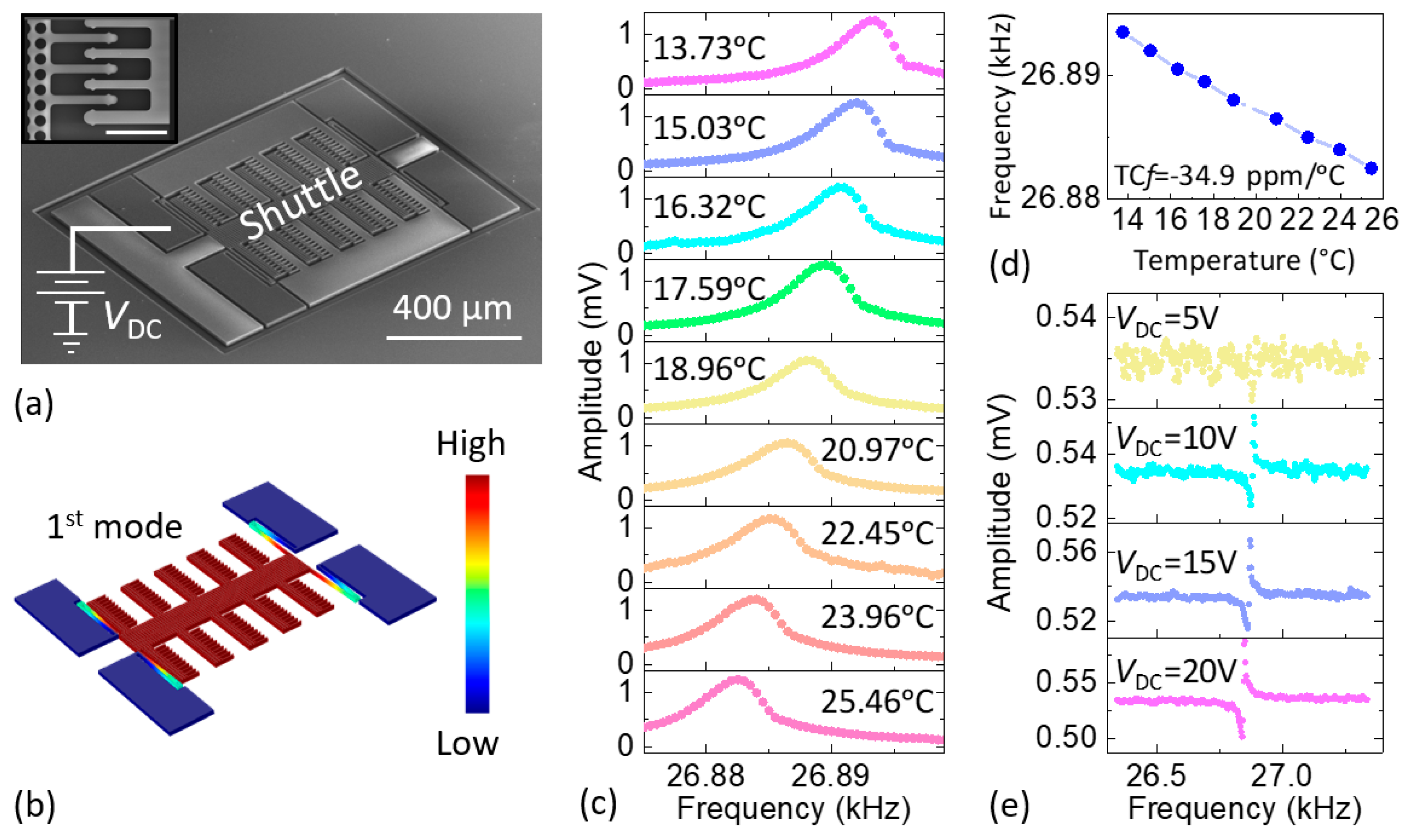
2.1. Overview of the SOI MEMS Resonator

We use SC-Si MEMS comb-drive resonators manufactured in a silicon-on-insulator (SOI) process at wafer scale to ensure high-Q and low phase noise. The SC-Si comb drive devices were fabricated on a 4-inch SOI wafer with a top device layer of 12 µm-thick SC-Si and an oxide (SiO2) with thickness of 2 µm. We first performed standard photolithography with a resolution of 1 µm to pattern the wafer. The top SC-Si layer not protected by photoresist was etched away by the Bosch process in a deep reactive ion etching (DRIE). The wafer was then diced into 5 mm × 5 mm chips. After etching in buffered oxide etch (BOE) to remove the SiO2 under the comb drive shuttle, chips were released in a critical point dryer (CPD) to prevent stiction to the substrate. Finally, aluminum (Al) wire bonding was performed on the selective pads for electrical interfacing. As shown in Figure 2a, the fabricated comb-drive SOI MEMS device has an overall length, width, and thickness of 900 µm, 700 µm, and 20 µm, respectively. In addition, the comb-drive fingers are 2 µm apart. We use finite element method (FEM) simulations in COMSOL Multiphysics to study the vibration pattern and mode shape of the first in-plane flexural resonant mode (see Figure 2b). Figure 2 also summarizes the results from optical characterization of the device resonance, which were obtained by using a custom-built laser interferometer specially engineered for ultrasensitive detection of in-plane resonance modes [21,22]. The optically measured resonant frequency for a DC polarization voltage of VDC = 20 V is f ≈ 26.8 kHz at room temperature (the measurement system is shown in Figure S1 in the Supplementary Materials), with a quality factor of Q = 13,000 at room temperature and in a moderate vacuum of ~5 mTorr. Figure 2c shows the optothermally excited, optically detected resonance responses [21,22] of the device as a function of temperature (at VDC = 20 V); we control the latter with a Peltier cooler. We then extract the resonance frequency versus temperature from the optically measured data (see Figure 2d). The figure shows that this MEMS device has a negative TCf of −34.9 ppm/°C, which is similar to other SC-Si devices in the literature. Figure 2e shows that the resonance frequency also shifts with the DC polarization voltage. We use these empirical measurement results for temperature compensation, as we shall describe in later sections.

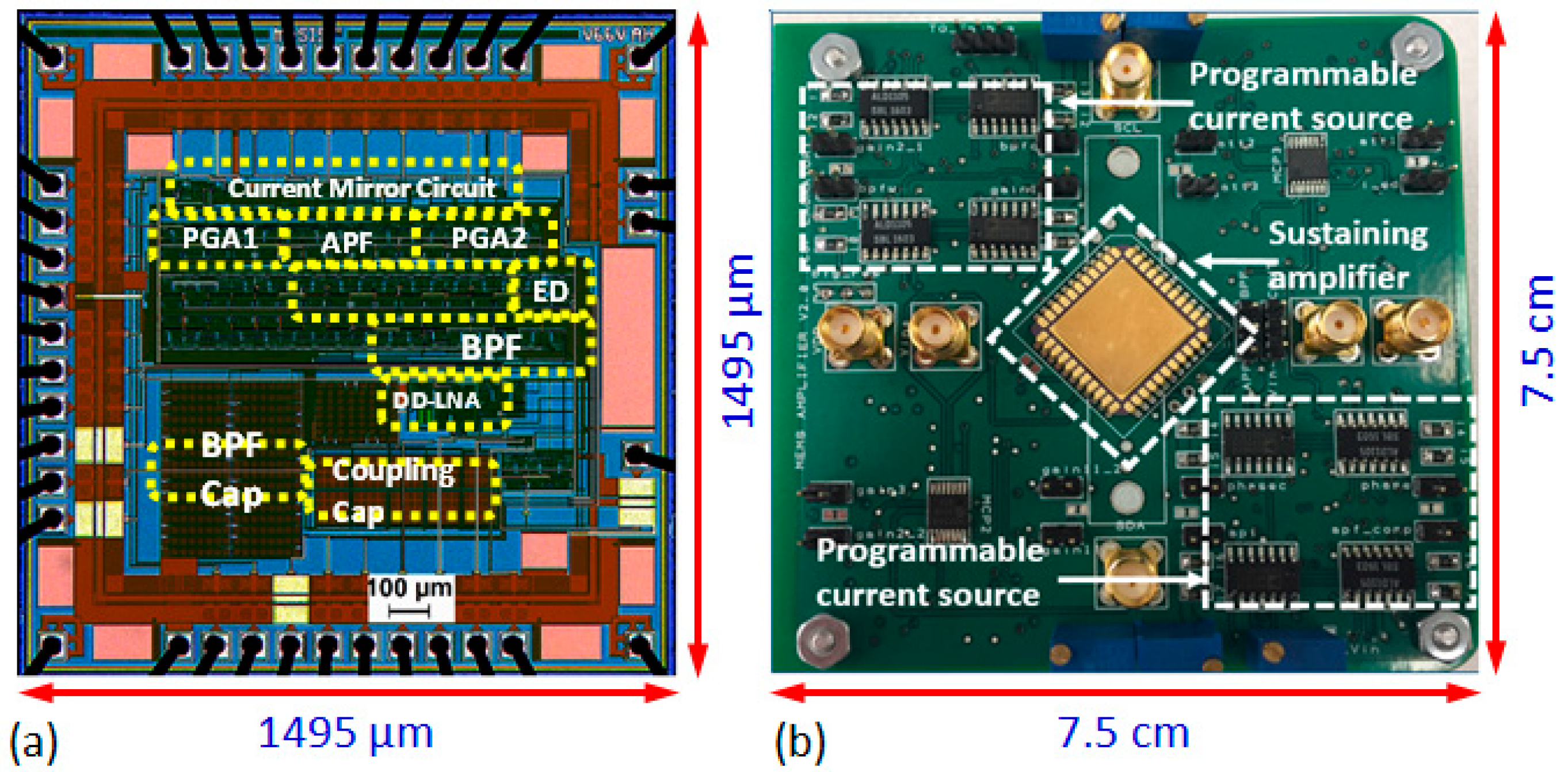
2.2. Overview of the Programmable Single-Chip CMOS Sustaining Amplifier

We have designed and fabricated a single-chip sustaining amplifier using the OnSemi 0.5 μm CMOS process and interfaced it with the MEMS resonator as illustrated in Figure 3a. The chip (see Figure 3b) contains a differential-difference low-noise amplifier (DD-LNA), two second-order band-pass filters (BPFs), three all-pass filters (APFs) used as phase shifters, variable gain amplifiers (VGAs), an automatic level control (ALC), a “background compensation network” (BCN) to cancel the parasitic electrical capacitance of the resonator, and an op-amp-based output buffer [23]. Various parameters of these blocks can be set by using programmable current sources implemented on the test board.
To integrate the SOI MEMS chip and the CMOS amplifier chip, we connect the two differential inputs of the DD-LNA to the MEMS resonator and the BCN, respectively. The DD structure eliminates unwanted capacitive coupling between these terminals. The measured 1/f corner frequency of the LNA is <10 kHz. We use a gate-input wide-linear-range operational transconductance amplifier (WLR-OTA) as the basic building block for the rest of the circuit. The WLR-OTA uses source degeneration and bump linearization to improve the input-referred linear range (VL) [24]. We use this OTA to implement second-order Gm-C BPFs that determine the frequency response of the amplifier, i.e., select a particular resonant mode. Each BPF uses two OTAs in a negative feedback loop to gyrate (invert) the impedance of a capacitor to realize an active inductor, since passive on-chip ones are impractical at such low frequencies. A third OTA acts as a variable resistor to form a parallel RLC circuit, and the OTA bias currents are adjusted to set the resulting center frequency and Q.
Similarly, we use the OTA to implement Gm-C APFs that control the overall phase shift of the amplifier, which enables the phase criterion for oscillations to be satisfied for the chosen mode. Each APF provides unity voltage gain and a frequency-dependent phase shift of −2tan−1 (ωt), where t = C/Gm. Thus, each APF provides a phase shift of 0–180° as t is adjusted from 0 to ∞ via an off-chip bias currents. However, in practice, t can only be varied over a finite range, which reduces the useful control range to ~120°. Hence three cascaded APFs are used for ~360° control. The maximum signal amplitude for total harmonic distortion (THD) <5% is ≈ 180 mV; this is largely limited by the OTAs.
Four cascaded VGAs control the voltage gain of the amplifier, i.e., enable the gain criterion for oscillations to be satisfied for the chosen mode. Each VGA uses two OTAs to set the gain, and a third OTA to create a high-pass filter. The latter allows the VGAs to be AC-coupled, which prevents accumulation of DC offset and low-frequency interference. The chip also includes an ALC that regulates the oscillator’s output voltage amplitude (VOUT) by adjusting the VGA gain. This reduces amplitude-to-phase noise conversion and prevents accidental damage to the MEMS resonator due to overload.
The amplitude- and phase-tunable BCN is designed to cancel the parasitic electrical feedthrough of the MEMS resonator. Such feedthrough, which is generally broadband, makes it difficult for the system to oscillate at the true optimal mechanical resonance frequency [25]. This is undesirable, since off-resonance operation degrades close-in (low offset frequency) phase noise. The BCN drives an on-chip capacitor (Cf ≈ 28 fF) that feeds back a compensation signal to the negative input terminal of the LNA.
Electrical characterization of the sustaining amplifier shows that the center frequency and Q of the BPF are adjustable from ~10 to ~90 kHz and from 0.5 to 9, respectively, while the APF phase shift can be adjusted over the full 360° range as expected. Moreover, the peak amplifier gain can be adjusted from 0 to 80 dB by using the VGAs, which is sufficient to overcome the transmission loss of typical comb-drive MEMS resonators within this frequency range.
The entire amplifier core occupies a layout area of 1150 μm × 1150 μm, and operates at a supply voltage of 3.3 V. Figure 4a shows a die micrograph of the sustaining amplifier. The input-referred noise of the amplifier with the BPF center frequency set to f = 26 kHz is ~7.2 nV/Hz1/2, which agrees with circuit simulations and corresponds to an equivalent noise resistance of Rn = 4 kΩ at room temperature. Moreover, Rn is typically much smaller than Rm, the motional resistance of comb-drive MEMS resonators in this frequency range. Thus, the close-in phase noise of the oscillator will be dominated by the high-Q resonator, as desired. Details of the measured specifications and performance of the chip are summarized in Table 1.

3. Oscillator Referred to the Single-Crystal SOI MEMS Resonator

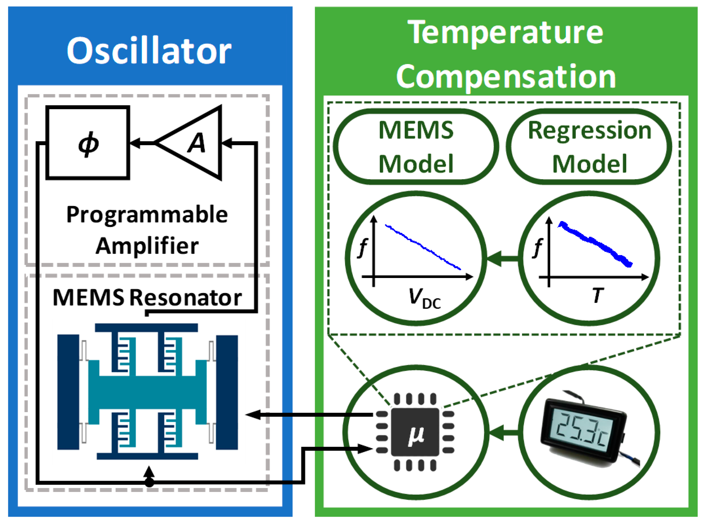
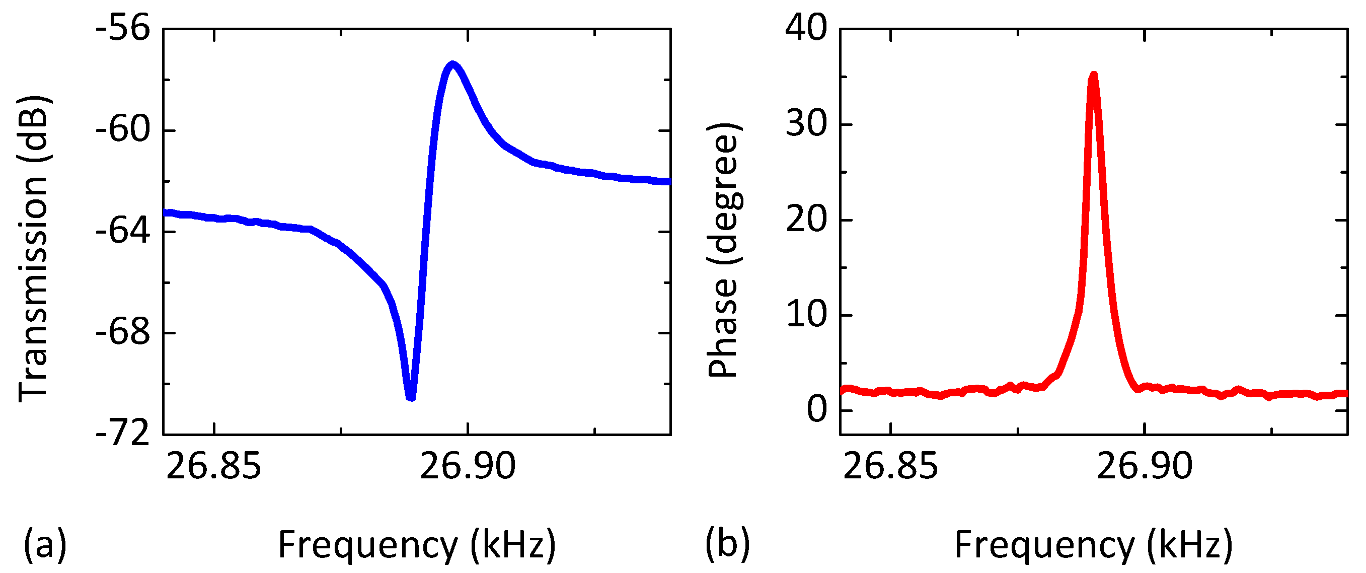
3.1. Oscillator System

The packaged sustaining amplifier chip is mounted on a test board designed to fit inside a vacuum chamber (~5 mTorr, room temperature) along with the SOI MEMS resonator. The board only needs four connections: power, output, and a two-wire I2C bus. An external MCU uses the bus to program 16 on-board digital potentiometers. The latter are combined with op-amps to realize programmable bias current generators that, in turn, set all on-chip parameters with 8-bit precision. Figure 5 shows the measured open-loop feed-forward transmission (magnitude and phase) using the MEMS and sustaining amplifier for a DC polarization voltage of VDC = 20 V and a drive amplitude of −10 dBm. We then create a MEMS-referenced oscillator by programming the BPFs, APFs, and VGAs to realize enough gain and the correct phase near resonance. In addition, we program the ALC to set the output amplitude to VOUT ≈ 400 mV.
The performance of the oscillator is monitored by using a spectrum analyzer (Agilent 4395A, Keysight Technologies, Santa Rosa, CA, USA) and a frequency counter (Agilent 53132A, Keysight Technologies, USA). The measured single-sideband (SSB) phase noise spectrum of the MEMS-referenced oscillator at ambient temperature is shown in Figure 6a, while the dependence of the oscillation frequency on the DC polarization voltage VDC is shown in Figure 6b. Note that the oscillation frequency is a non-monotonic function of VDC.

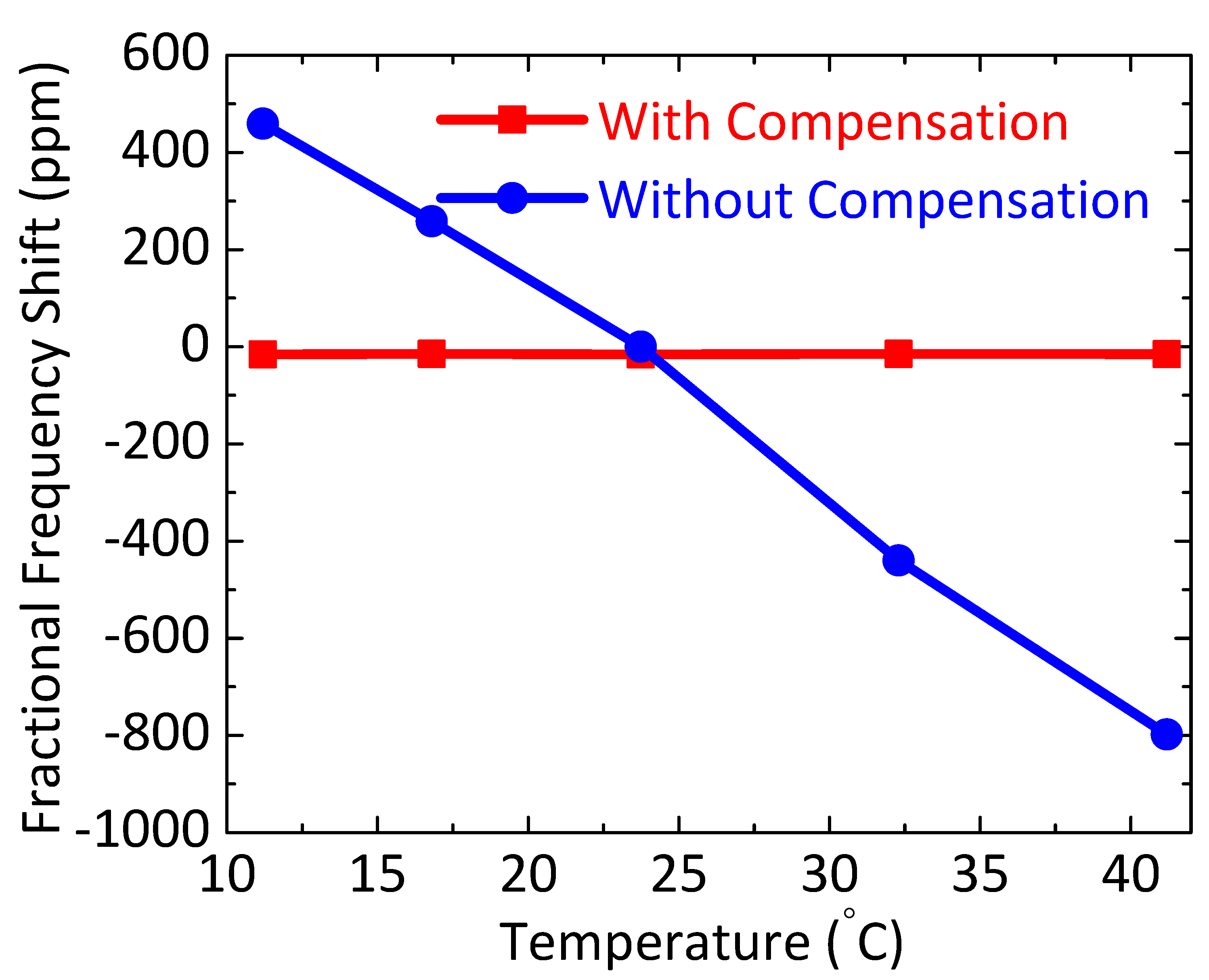
3.2. Temperature Compensation of the MEMS-Referenced Oscillator

Figure 7 shows the block diagram of the overall real-time temperature compensation loop (including calibration of the oscillator using a linear model). The overall real-time temperature compensation loop (i.e., data acquisition, calibration, post-processing, and command execution) has been implemented in a software environment (MATLAB, R2018a). The oscillator is placed inside a vacuum chamber as shown in the left side of the block diagram along with a digital temperature sensor (MCP9808, Microchip Technology, Chandler, AZ, USA) with a resolution of ±0.25 °C. The sensor is directly attached to the DIP24 package containing the wire-bonded resonator to ensure that it measures device temperature. A miniaturized development board (Arduino Uno R3, Arduino, New York, NY, USA) based on an ATmega328 MCU (Atmel Corporation, San Jose, CA, USA) with 32 KB memory acts as the system controller. The MCU is used to program 16 on-board digital potentiometers using a 2-wire I2C bus and also acquires data from the temperature sensor. A MATLAB script stores all real-time experimental T-f data vectors and sends commands to set the desired MEMS VDC voltage with a resolution of 5 mV using a source meter unit (Keithley 2450, Agilent Technologies, Santa Clara, CA, USA) programmed over GPIB. In addition, the MATLAB script implements temperature-to-frequency (T-f) and either frequency-to-voltage (f-V) or frequency-to-phase (f-ϕ) conversion functions to realize the proposed temperature control loop.
During calibration, the device temperature is accurately set by using a Peltier module (CP08-63-06, Laird Technology, Cleveland, OH, USA) which is powered from an external benchtop DC power supply. The frequency counter has been used to measure the oscillation frequency over a period of seven (7) days with a gate time (tg) of 100 ms. A data-driven linear model is then derived by using offline post-processing. The best-fitting model given is given by
f o s c = m × T + c ,
where T is the temperature (in °C), fosc is the oscillation frequency (in Hz), m is the slope, and c is the y-intercept. The coefficients of Equation (1) are computed by averaging the best-fitting values from 6 runs (individual values are shown in Table 2). These coefficients are used for temperature compensation. Specifically, Equation (1) is stored in MCU memory and used to calculate the optimal VDC in terms of the measured temperature. Figure 8a shows how the frequency of the uncompensated MEMS-referenced oscillator fluctuates due to room temperature variations; the estimated TCf = −41 ppm/°C is extracted from the fitting in Figure 8b. The result is in good agreement with the open-loop resonator TCf shown in Figure 2d, which suggests that the closed-loop TCf is dominated by the resonator and not the sustaining amplifier. A proportional control algorithm is then used to compensate for the measured TCf, and the resulting frequency stability is estimated using the Allan deviation, σA(τ), as a function of averaging time τ [26,27].
Figure 9a,b compare the stability of the temperature-compensated (red curve) and uncompensated (blue curve) oscillators when subject to small indoor temperature fluctuations (approximately ±0.5 °C, detailed statistics are shown in Figure S2 of the Supplementary Materials). The temperature-compensated oscillator achieves a fractional frequency stability of ~3.6 × 10⁻⁶ in the short-term (τ ~1 s), and ~3.7 × 10⁻⁶ for longer averaging times (τ ~1000 s). In the short-term regime (say τ < 100 s), temperature compensation noticeably improves the Allan deviation. Long-term drift dominates at averaging time of τ > 10,000 s; in this region, Allan deviation is significantly improved by compensating for temperature-related drifts in the resonance frequency. We expect such improvements to persist when the proposed temperature compensation method is extended to large batches of wafer-fabricated resonators, since the resonator TCf is mainly determined by the intrinsic material properties of SC-Si.
We have further verified the performance of the proposed compensation method by measuring oscillator frequency stability over a broader temperature range. For this purpose, we have varied the operating temperature of the resonator from 11.2 °C to 41.2 °C by using either a Peltier module (for cooling) or two ceramic space heaters (for heating). The temperature compensation loop is also modified to control both the MEMS DC polarization voltage (VDC) and the feedback phase shift (ϕ) of the sustaining amplifier to minimize the resulting frequency fluctuations. This is because the oscillation frequency is a non-monotonic function of VDC (see Figure 6b), so it is unsuitable for compensating large temperature variations and drifts. Thus, here we exploit ϕ as another degree of freedom for compensation.
Experimental results are shown in Figure 10 (with supporting data shown in Figure Figure S3 in the Supplementary Materials). The results in Table S1 are plotted in Figure 10. The figure shows that the uncompensated oscillator has the expected TCf of approximately −40 ppm/°C (dominated by the SC-Si resonator), while the compensated oscillator has near-zero TCf (within a measurement error of about ±3 ppm) over this temperature range.
Table 3 compares the performance of the proposed temperature-compensated oscillator with other kHz-range MEMS-referenced oscillators. Our design achieves low close-in phase noise and good long-term stability due to temperature compensation.

4. Discussion

Temperature-driven frequency fluctuations are ubiquitous, and are a major performance limiter for SC-Si MEMS-referenced oscillators. Other potential sources of frequency fluctuations include noise sources in the instrumentation [30,31,32], dielectric and charge fluctuations in the resonator, bulk and surface effects in the resonator [33], and limited dynamic range of the sustaining amplifier. The main purpose of the work is to build a temperature-compensated SC-SOI-MEMS oscillator (TCO) for use in low power applications such as IoT sensor nodes. In addition, further improvements in long-term stability can be obtained by replacing temperature compensation with temperature control (i.e., implementing an oven-controlled oscillator (OCO)) and/or by locking the oscillator to an external frequency reference such as GPS over long time scales [34,35]. However, TCOs are more attractive for low-power applications than OCOs because they consume much less power.

5. Conclusions

We have demonstrated improved long-term frequency stability by implementing temperature compensation for a single-crystal SOI MEMS-referenced oscillator with a reconfigurable CMOS sustaining amplifier chip. A software-defined compensation loop has been developed for this purpose. Experimental results confirm the effectiveness of the approach in significantly reducing the Allan deviation on time scales τ > 10,000 s. These results open up new potential applications for MEMS-referenced oscillators, including high-precision sensing, environmental sensing and monitoring, next-generation wireless communication, and navigation.

Supplementary Materials

The following are available online at https://www.mdpi.com/2072-666X/9/11/559/s1, Figure S1. Schematic of the optical measurement system used for characterizing the open-loop resonance response and TCf of the single-crystal SOI MEMS comb-drive resonator. Figure S2. Power spectral density (PSD) and stability estimation: (a) PSD of uncompensated and compensated oscillation frequency; (b) PSD of ambient temperature fluctuations; (c) Allan deviation of uncompensated and compensated oscillation frequency; and (d) Allan deviation of the temperature data shown in (b). Figure S3. Oscillation frequency traces versus time, measured at five different temperature values set and controlled by the sample heating and cooling modules, for oscillators (a) without and (b) with temperature compensation, respectively. Inset plot in (b) shows zoomed-in view of the red box in (b). Table S1. Fractional frequency shift with and without temperature compensation.

Author Contributions

M.S.I. designed the CMOS sustaining amplifier and performed the temperature compensation algorithm and relevant measurements. Y.X. and J.L. designed and fabricated the SOI MEMS resonators. R.W., J.L. and Y.X. measured the open-loop characteristics. M.S.I., R.W. and J.L. performed closed-loop characterization. S.M. and P.X.-L.F. conceived and supervised the project.

Funding

This work was supported by the National Science Foundation (NSF) under grant ECCS-1509721.

Acknowledgments

We would like to thank the MOSIS Educational Program (MEP) for chip fabrication. We are grateful to the financial support from the National Science Foundation (Grant ECCS-1509721).

Conflicts of Interest

The authors declare no conflicts of interest regarding the publication of this paper.

References

  1. Vig, J.R. Temperature-insensitive dual-mode resonant sensors—a review. IEEE Sens. J. 2001, 1, 62–68. [Google Scholar] [CrossRef]
  2. Nguyen, C.T.-C. MEMS technology for timing and frequency control. IEEE Trans. Ultrason. Ferroelectr. Freq. Control 2007, 54, 251–270. [Google Scholar] [CrossRef] [PubMed] [Green Version]
  3. Nguyen, C.T.-C.; Howe, R.T. An integrated CMOS micromechanical resonator high-Q oscillator. IEEE J. Solid State Circuits 1999, 34, 440–455. [Google Scholar] [CrossRef]
  4. Thakar, V.; Rais-Zadeh, M. Temperature-compensated piezoelectrically actuated Lame mode resonators. In Proceedings of the IEEE International Conference on Micro Electro Mechanical Systems (MEMS 2014), San Francisco, CA, USA, 26–30 January 2014; pp. 214–217. [Google Scholar]
  5. Lee, H.; Partridge, A.; Assaderaghi, F. Low jitter and temperature stable MEMS oscillators. In Proceedings of the IEEE International Frequency Control Symposium (IFCS), Baltimore, MD, USA, 21–24 May 2012; pp. 266–270. [Google Scholar]
  6. Clark, J.R.; Nguyen, C.T.-C. Mechanically temperature-compensated flexural-mode micromechanical resonators. In Proceedings of the International Electron Devices Meeting, San Francisco, CA, USA, 10–13 December 2000; pp. 399–402. [Google Scholar]
  7. Hsu, W.-T.; Nguyen, C.T.-C. Stiffness-compensated temperature-insensitive micromechanical resonators. In Proceedings of the International Conference on Micro Electro Mechanical Systems (MEMS 2002), Las Vegas, NV, USA, 20–24 January 2002; pp. 731–734. [Google Scholar] [Green Version]
  8. Sundaresan, K.; Allen, P.E.; Ayazi, F. Process and temperature compensation in a 7-MHz CMOS clock oscillator. IEEE J. Solid State Circuits 2006, 41, 433–442. [Google Scholar] [CrossRef]
  9. Salvia, J.C.; Melamud, R.; Chandorkar, S.A.; Lord, S.F.; Kenny, T.W. Real-time temperature compensation of mems oscillators using an integrated micro-oven and a phase-locked loop. J. Microelectromech. Syst. 2010, 19, 192–201. [Google Scholar] [CrossRef]
  10. Samarao, A.K.; Ayazi, F. Temperature compensation of silicon resonators via degenerate doping. IEEE Trans. Electron. Devices 2012, 59, 87–93. [Google Scholar] [CrossRef]
  11. Rais-Zadeh, M.; Thakar, V.A.; Wu, Z.; Peczalski, A. Temperature compensated silicon resonators for space applications. In Proceedings of the Reliability, Packaging, Testing, and Characterization of MOEMS/MEMS and Nanodevices XII, San Francisco, CA, USA, 9 March 2013; SPIE: Bellingham, WA, USA, 2013; Volume 8614. [Google Scholar]
  12. Melamud, R.; Kim, B.; Chandorkar, S.A.; Hopcroft, M.A.; Agarwal, M.; Jha, C.M.; Kenny, T.W. Temperature-compensated high-stability silicon resonators. Appl. Phys. Lett. 2007, 90, 244107. [Google Scholar] [CrossRef]
  13. Thakar, V.A.; Wu, Z.; Figueroa, C.; Rais-Zadeh, M. A temperature-stable clock using multiple temperature-compensated micro-resonators. In Proceedings of the IEEE International Frequency Control Symposium (IFCS), Taipei, Taiwan, 19–22 May 2014; pp. 1–4. [Google Scholar]
  14. Nguyen, C.T.-C. Micromechanical resonators for oscillators and filters. In Proceedings of the International Ultrasonics Symposium, Seattle, WA, USA, 7–10 November 1995; pp. 489–499. [Google Scholar]
  15. Serrano, D.E.; Tabrizian, R.; Ayazi, F. Tunable piezoelectric MEMS resonators for real-time clock. In Proceedings of the IEEE International Frequency Control Symposium and the European Frequency and Time Forum (IFCS/EFTF), San Francisco, CA, USA, 2–5 May 2011; pp. 1–4. [Google Scholar]
  16. Nguyen, C.T.-C. Frequency-selective MEMS for miniaturized low-power communication devices. IEEE Trans. Microw. Theory Tech. 1999, 47, 1486–1503. [Google Scholar] [CrossRef] [Green Version]
  17. Perrott, M.H.; Salvia, J.C.; Lee, F.S.; Partridge, A.; Mukherjee, S.; Arft, C.; Jintae, K.; Arumugam, N.; Gupta, P.; Tabatabaei, S.; et al. A temperature-to-digital converter for a MEMS-based programmable oscillator with <±0.5-ppm frequency stability and <1-ps integrated jitter. IEEE J. Solid State Circuits 2013, 48, 276–291. [Google Scholar] [CrossRef]
  18. Villanueva, L.G.; Kenig, E.; Karabalin, R.B.; Matheny, M.H.; Lifshitz, R.; Cross, M.C.; Roukes, M.L. Surpassing fundamental limits of oscillators using nonlinear resonators. Phys. Rev. Lett. 2013, 110, 177208. [Google Scholar] [CrossRef] [PubMed]
  19. Villanueva, L.G.; Karabalin, R.B.; Matheny, M.H.; Kenig, E.; Cross, M.C.; Roukes, M.L. A nanoscale parametric feedback oscillator. Nano Lett. 2011, 11, 5054–5059. [Google Scholar] [CrossRef] [PubMed]
  20. Islam, M.S.; Lee, J.; Wei, R.; Feng, P.X.-L.; Mandal, S.M. Programmable & reconfigurable sustaining amplifiers for MEMS/NEMS referenced multimode oscillators. In Proceedings of the Techical Digest of the 18th Solid-State Sensors, Open Poster WOP-12, Actuators & Microsystems Workshop (Hilton Head 2018), Hilton Head Island, SC, USA, 3–7 June 2018. [Google Scholar]
  21. Lee, J.; Kaul, A.B.; Feng, P.X.-L. Carbon nanofiber high frequency nanomechanical resonators. Nanoscale 2017, 9, 11864–11870. [Google Scholar] [CrossRef] [PubMed]
  22. McCandless, J.P.; Lee, J.; Kuo, H.I.; Pashaei, V.; Mehregany, M.; Zorman, C.A.; Feng, P.X.-L. Electrical and optical transduction of single-crystal 3C-SiC comb-drive resonators in SiC-on-Insulator (SiCOI) Technology. In Proceedings of the Techical Digest of the 17th Solid-State Sensors, Actuators & Microsystems Workshop (Hilton Head 2016), Hilton Head Island, SC, USA, 5–9 June 2016; pp. 9–12. [Google Scholar]
  23. Islam, M.S.; Singh, S.K.; Mandal, S. A programmable sustaining amplifier for reconfigurable MEMS-referenced oscillators. In Proceedings of the IEEE International Midwest Symposium on Circuits and Systems (MWSCAS), Boston, MA, USA, 6–9 August 2017; pp. 41–44. [Google Scholar]
  24. Sarpeshkar, R.; Lyon, R.F.; Mead, C.A. A low-power wide-linear-range transconductance amplifier. Analog Integr. Circuits Signal Process. 1997, 13, 123–151. [Google Scholar] [CrossRef]
  25. Feng, X.-L.; White, C.J.; Hajimiri, A.; Roukes, M.L. A self-sustaining ultrahigh-frequency nanoelectromechanical oscillator. Nat. Nanotechnol. 2008, 3, 342–346. [Google Scholar] [CrossRef] [PubMed] [Green Version]
  26. Allan, D.W. Time and frequency (time-domain) characterization, estimation, and prediction of precision clocks and oscillators. IEEE Trans. Ultrason. Ferroelectr. Freq. Control. 1987, 34, 647–654. [Google Scholar] [CrossRef] [PubMed]
  27. Antonio, D.; Zanette, D.H.; López, D. Frequency stabilization in nonlinear micromechanical oscillators. Nat. Commun. 2012, 3, 806. [Google Scholar] [CrossRef] [PubMed] [Green Version]
  28. Young, D.J.; Pehlivanoǧlu, I.E.; Zorman, C.A. Silicon carbide MEMS-resonator-based oscillator. J. Micromech. Microeng. 2009, 19, 115027. [Google Scholar] [CrossRef]
  29. Zaliasl, S.; Salvia, J.C.; Hill, G.C.; Chen, L.W.; Joo, K.; Palwai, R.; Arumugam, N.; Phadke, M.; Mukherjee, S.; Lee, H.C.; et al. A 3 ppm 1.5 × 0.8 mm2 1.0 μA 32.768 kHz MEMS-based oscillator. IEEE J. Solid State Circuits 2015, 50, 291–302. [Google Scholar] [CrossRef]
  30. Zhang, Y.; Moser, J.; Güttinger, J.; Bachtold, A.; Dykman, M.I. Interplay of driving and frequency noise in the spectra of vibrational systems. Phys. Rev. Lett. 2014, 113, 255502. [Google Scholar] [CrossRef] [PubMed]
  31. Steele, G.A.; Hüttel, A.K.; Witkamp, B.; Poot, M.; Meerwaldt, H.B.; Kouwenhoven, L.P.; van der Zant, H.S.J. Strong coupling between single-electron tunneling and nanomechanical motion. Science 2009, 325, 1103–1107. [Google Scholar] [CrossRef] [PubMed]
  32. Miao, T.; Yeom, S.; Wang, P.; Standley, B.; Bockrath, M. Graphene nanoelectromechanical systems as stochastic-frequency oscillators. Nano Lett. 2014, 14, 2982–2987. [Google Scholar] [CrossRef] [PubMed]
  33. Sansa, M.; Sage, E.; Bullard, E.C.; Gély, M.; Alava, T.; Colinet, E.; Naik, A.K.; Villanueva, L.G.; Duraffourg, L.; Roukes, M.L.; et al. Frequency fluctuations in silicon nanoresonators. Nat. Nanotechnol. 2016, 11, 552–558. [Google Scholar] [CrossRef] [PubMed] [Green Version]
  34. Cheng, C.L.; Chang, F.R.; Tu, K.Y. Highly accurate real-time GPS carrier phase-disciplined oscillator. IEEE Trans. Instrum. Meas. 2005, 54, 819–824. [Google Scholar] [CrossRef] [Green Version]
  35. Lombardi, M.A. The use of GPS disciplined oscillators as primary frequency standards for calibration and metrology laboratories. J. Meas. Sci. 2008, 3, 56–65. [Google Scholar] [CrossRef]
Figure 1. Overview of the temperature-compensated oscillator.
Micromachines 09 00559 g001
Figure 2. Single-crystal Si-on-insulator (SOI) comb-drive MEMS resonator characteristics. (a) Scanning electron microscopy (SEM) image. The inset shows a partial zoom-in view of the comb drive and fingers. Scale bar: 20 μm; (b) Simulated vibration pattern and mode shape for the first in-plane resonance mode; (c) Optically measured transmission data and frequency response around the first resonance as temperature increases; (d) Open-loop resonance frequency dependence on temperature for the extraction of TCf from the data in (c); (e) Electrically measured transmission and frequency response when various values of the DC polarization voltage are applied to the shuttle. The responses in (c,e) have not been converted to dimensionless transfer functions since the measurement path includes both electrical and optical components, which makes it difficult to derive absolute calibration factors.
Micromachines 09 00559 g002
Figure 3. (a) Simplified system diagram illustrating the integration of the MEMS resonator chip with the CMOS sustaining amplifier chip; (b) Simplified block diagram of the programmable single-chip CMOS sustaining amplifier (corresponding to the same color-coded dashed-line box in (a)).
Micromachines 09 00559 g003
Figure 4. (a) Die micrograph of the CMOS sustaining amplifier; (b) Test board used for characterizing the amplifier and integrating with the MEMS resonator to build the oscillator.
Micromachines 09 00559 g004
Figure 5. Electrical characterization results of the single-crystal SOI MEMS resonator. (a) Measured transmission (dB) and frequency response of the resonance; (b) Open-loop phase (degrees) around the first mode for VDC = 20 V and an input power of −10 dBm.
Micromachines 09 00559 g005
Figure 6. (a) Measured single-sideband (SSB) phase noise of the single-crystal SOI MEMS oscillator for VDC = 20 V; (b) Measured electrical tuning of the oscillator frequency as a function of VDC (approximately −1 Hz/V for voltages >16 V).
Micromachines 09 00559 g006
Figure 7. Block diagram of the model calibration procedure, and the proposed real-time temperature compensation loop.
Micromachines 09 00559 g007
Figure 8. (a) Measured temperature variation (top) and fluctuation of oscillation frequency (bottom) for the uncompensated oscillator over 24 h; (b) Linear fit of the oscillation frequency versus temperature.
Micromachines 09 00559 g008
Figure 9. (a) Instantaneous frequency of the uncompensated and compensated oscillators over 24 h; (b) Measured Allan deviation σA (τ) with and without real-time temperature compensation.
Micromachines 09 00559 g009
Figure 10. Fractional frequency shift (in ppm) as the device temperature is varied, measured from both the temperature-compensated and uncompensated oscillators over a temperature range of 10 to 45 °C.
Micromachines 09 00559 g010
Table 1. Summary of the electrical specifications and performance of the programmable sustaining amplifier.
Chip ComponentsPerformance
Low-Noise Amplifier (LNA)
(for IB = 2.5 µA)
Gain: 12 dB; Bandwidth: ~1 MHz
Thermal Noise PSD: 13 nV/Hz1/2
1/f Corner Frequency: <10 kHz
Band-Pass Filter (BPF)Center Frequency (f0): 2–90 kHz; Q: 1–8
Dynamic Range (DR): 60.7 dB (24 kHz, Q = 2)
Linear Range: 500 mV (THD < 5%, 24 kHz, Q = 2)
All-Pass Filter (APF)Phase Control: 0–360°
Phase Control Sensitivity: ~0.6°/nA
Variable Gain Amplifier (VGA)Settable Gain: 0–80 dB
Automatic Level Control (ALC)Amplitude Control Voltage (VED): 0–0.5 V
ED Time Constant: 8-Bit control
Background Compensation PathGain Control: −20 to 40 dB
Phase Control: 0–180°
Table 2. Look-up table (LUT) used for temperature compensation.
Day #Fitted Coefficients
mc
1−1.02227,035
2−1.16926,964
3−1.45927,067
4−1.12826,997
5−1.132927,044
6−1.145826,968
Mean value−1.176127,012
Table 3. Comparison of performance between the temperature-compensated oscillator in this work and other MEMS-referenced oscillators in the same frequency range.
PropertiesThis Work[28][29][3]
Resonator Type and MaterialSingle-Crystal SOI Lateral Comb-Drive3C-SiC, Comb-DriveCapacitive Transduction H-Shaped Tuning ForkPoly-Si Two-Port, Folded-Beam, Comb-Drive
Modes of Oscillation3311
Oscillation Frequencies (fosc)~27.0 kHz (Mode 1 Only)27.1 kHz, 30.3 kHz, 24.2 kHz32.768 kHz16.5 kHz
Q-Factor13,00013,550,10,300 and 948052,00023,400
CMOS Sustaining Amplifier Chip0.5 μm CMOSDiscrete Components180 nm CMOSCMOS Transimpedance Amplifier (TIA)
Die Size1.5 mm × 1.5 mmDiscrete Components1.55 mm × 0.85 mm420 µm × 320 µm (Resonator Only)
Supply Voltage (VDD)3.3 V3.0 V1.4–4.5 V2.5 V
SSB Phase Noise−65 dBc/Hz @ 10 Hz Offset −78 dBc/Hz @ 12 Hz OffsetNot Reported−72 dBc/Hz @ 1 kHz Offset (Simulated)
FoM *133.61Not ReportedNot ReportedNot Reported
Startup Time~600 µsNot Reported0.2 sNot Reported
Real-Time Temperature CompensationYesNoYesNo
Temperature coeficients of frequency (TCf) −34 ppm/°C (MEMS only);
<±3 ppm (TCO) over 11.2 °C to +41.2 °C
24.75 ppm /°C ** (rocking vibration mode of MEMS) over 26.85 °C to +426.85 °C±100 ppm (MEMS only);
±3 ppm (TCXO) & 100 ppm max (XO) over −40 °C to +85 °C
−10 ppm/°C (MEMS only)
over 26.85 °C to +96.85 °C
Year2018200920151999
* F o M = 20 log ( ω 0 Δ ω ) L ( Δ ω ) 10 log ( P C 1   m   W ) , ** ANSYS finite element simulation results.

