Nanomechanical Motion Transducers for Miniaturized Mechanical Systems
Abstract
:1. Introduction
1.1. Basic Parameters
1.2. Operation and Transducers
2. Actuation of Nanomechanical Motion
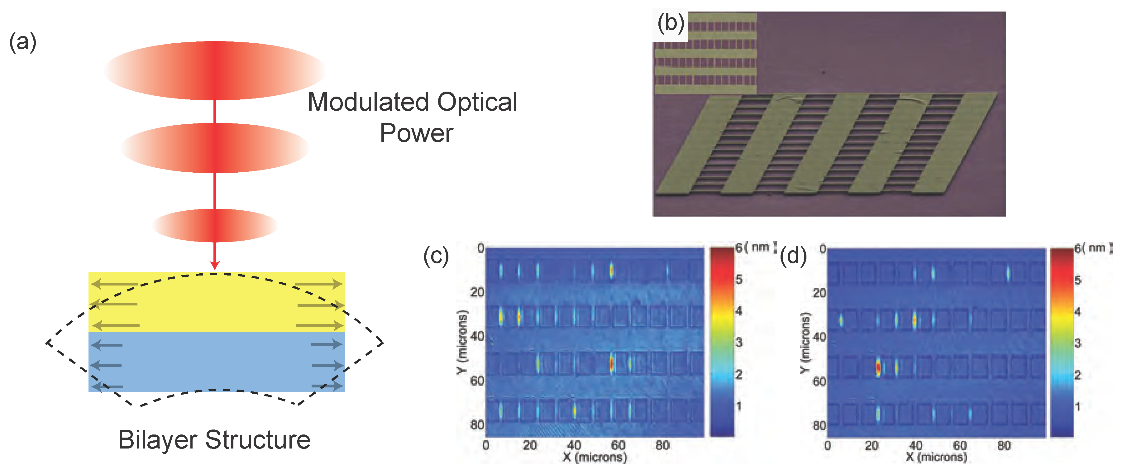
2.1. Optical Techniques
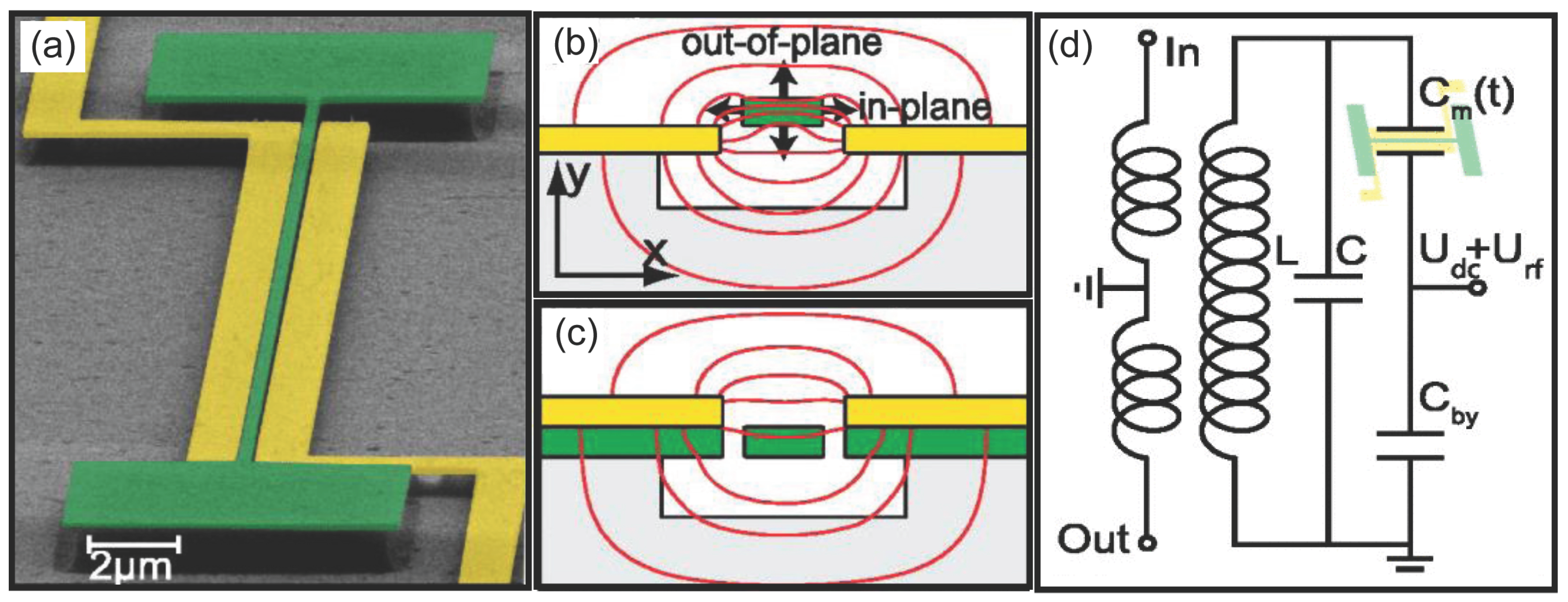
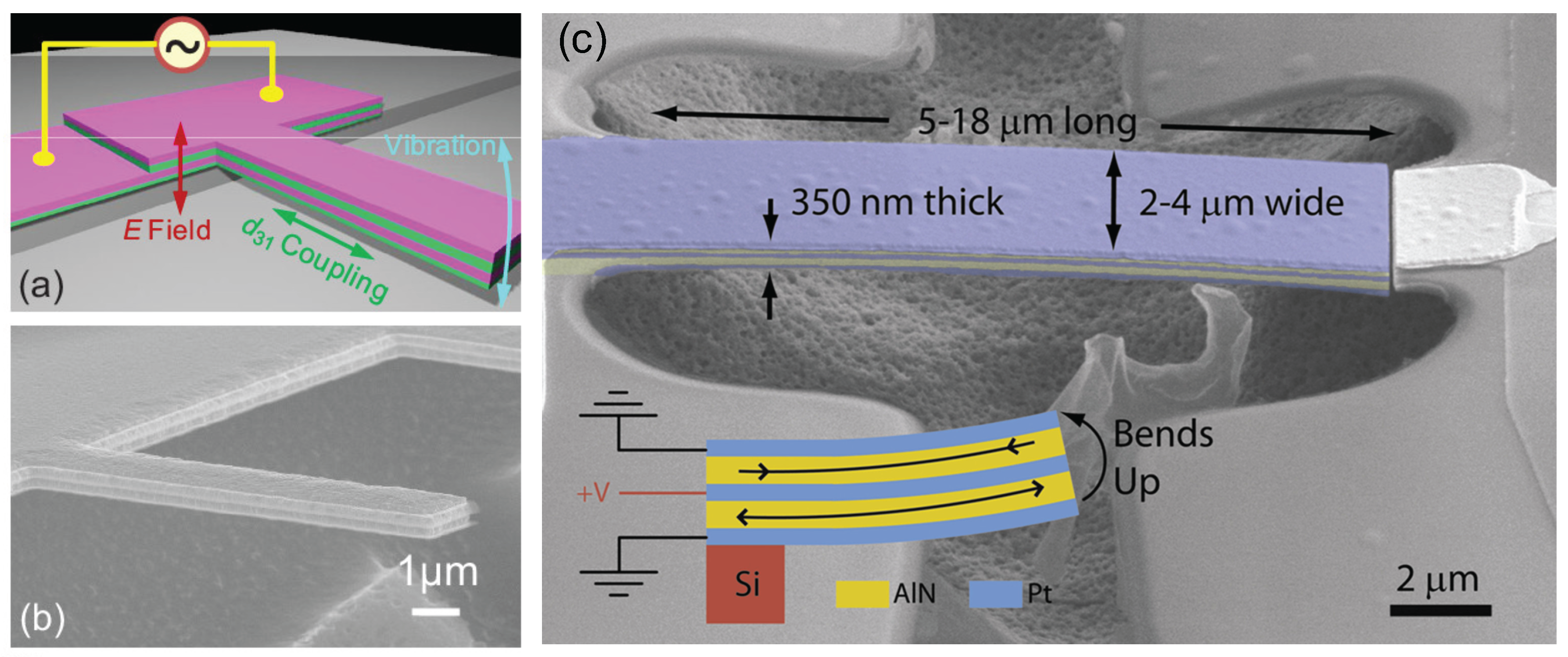
2.2. Electronic Coupling
3. Detection of Nanomechanical Motion
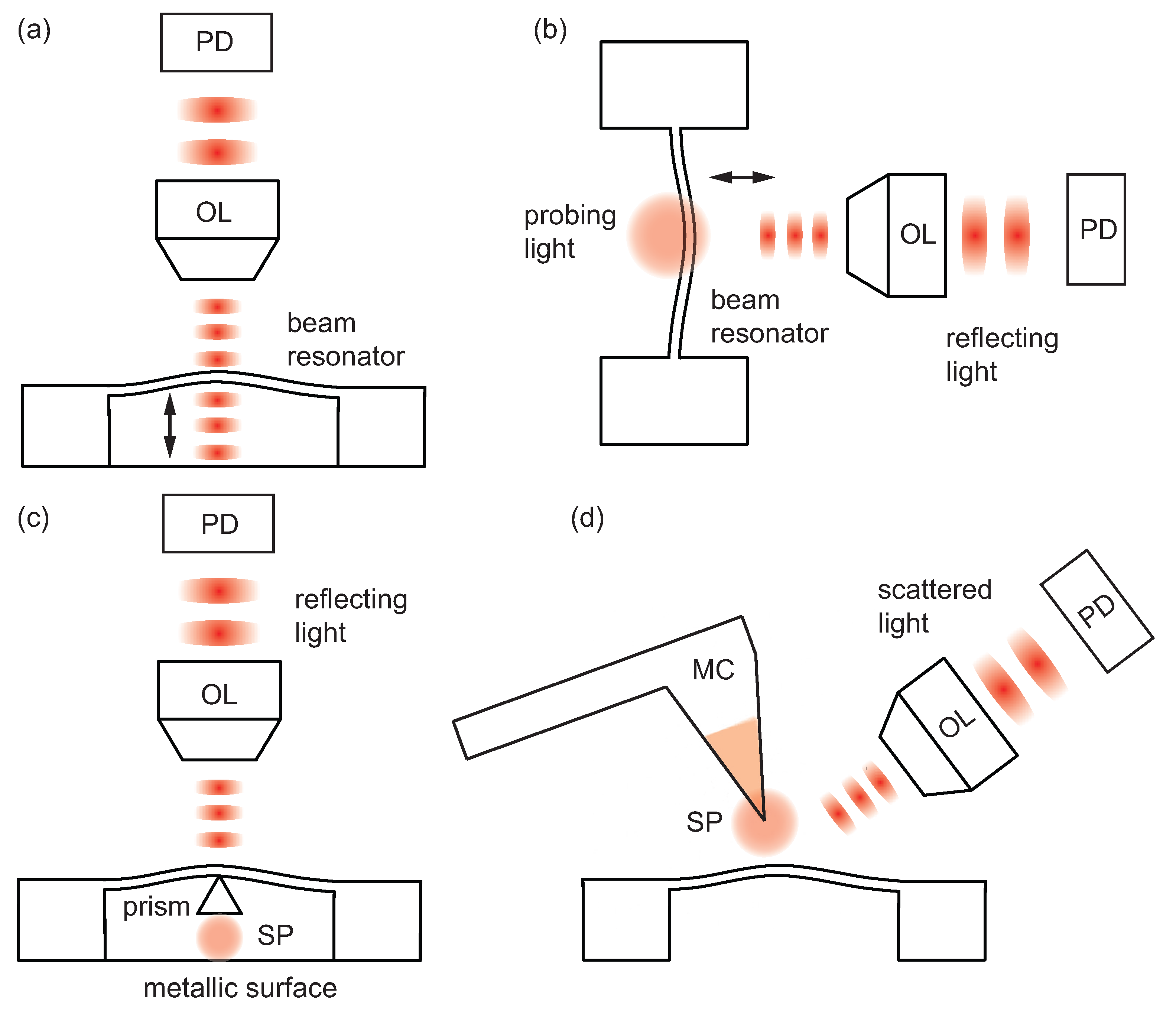
3.1. Techniques Based on Free-Space Optics
3.2. Integrated Optical Techniques
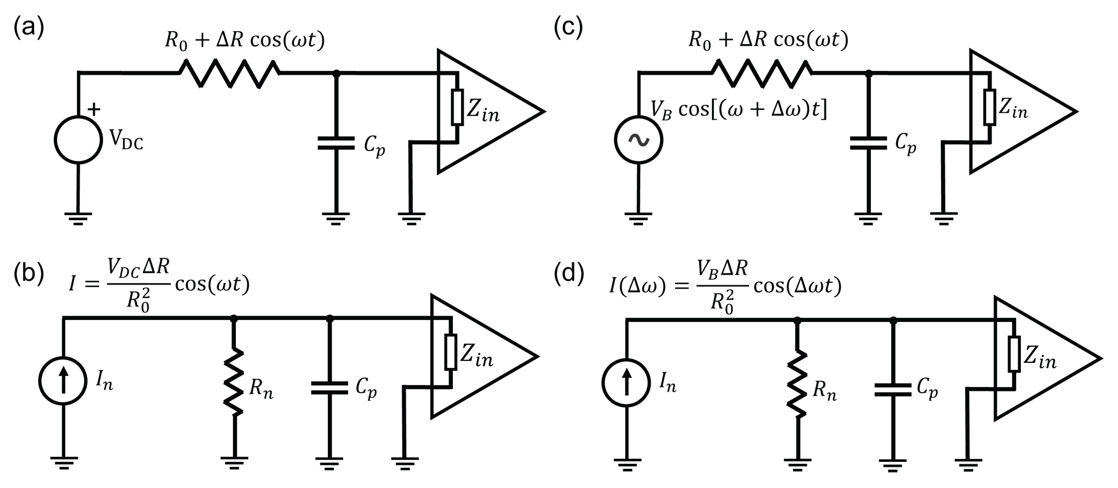
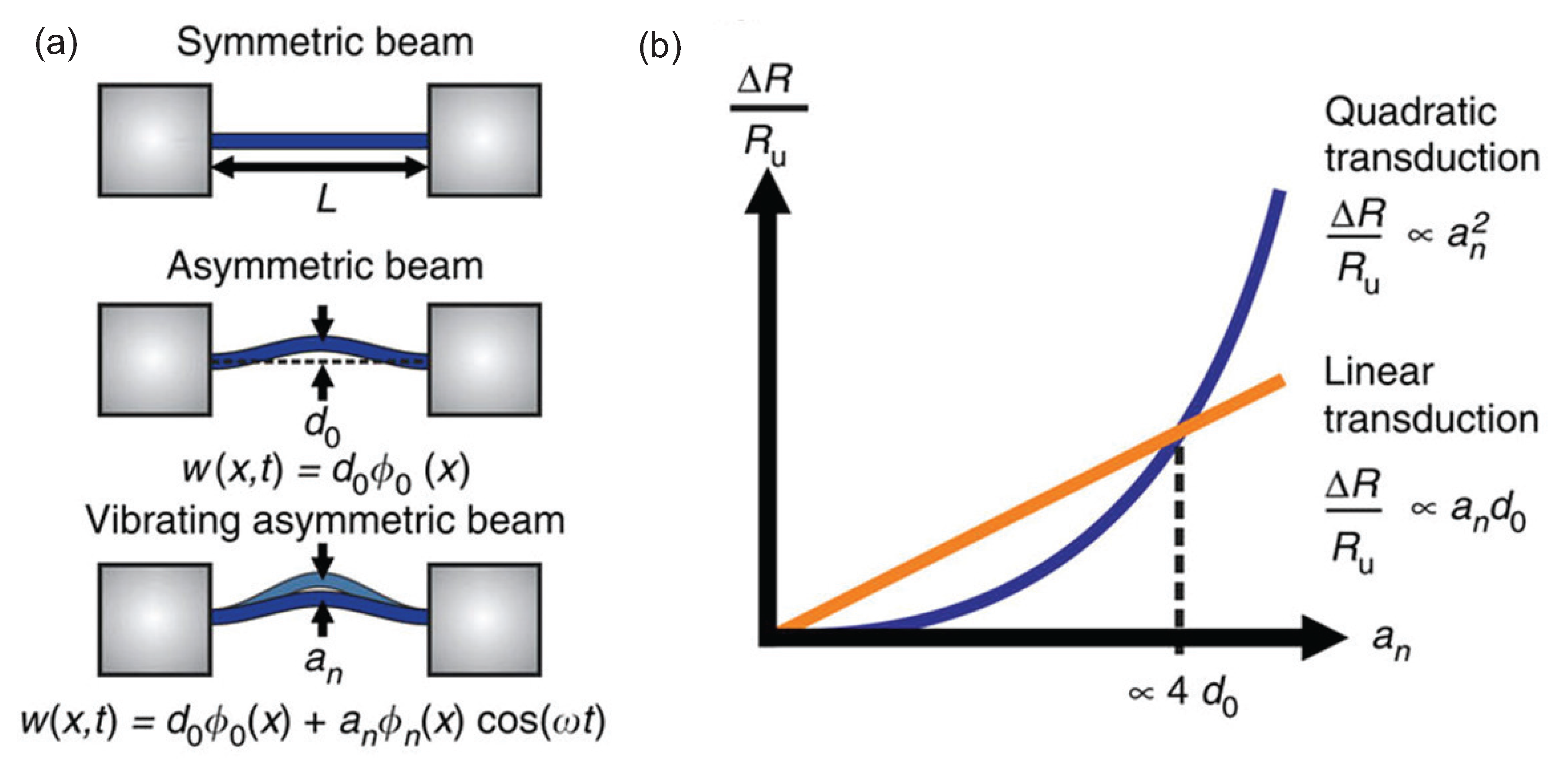
3.3. Electronic and Other Approaches
4. Conclusions and Outlook
Acknowledgments
Conflicts of Interest
Abbreviations
| AC | Alternating current |
| AFM | Atomic force microscopy |
| CMOS | Complementary metal–oxide–semiconductor |
| DC | Direct current |
| EMF | Electromotive force |
| MBE | Molecular beam epitaxy |
| MEMS | Micro-electro-mechanical systems |
| NEMS | Nano-electro-mechanical systems |
| NOEMS | Nano-opto-electro-mechanical systems |
| NOMS | Nano-opto-mechanical systems |
| PCB | Printed circuit board |
| Q or Q factor | quality factor |
| RF | Radiofrequency |
| SEM | Scanning electron microscopy |
| SET | Single-electron transistor |
| SOI | Silicon-on-insulator |
| SPM | Scanning probe microscopy |
| SQUID | Superconducting quantum interference devices |
| VHF | Very high frequency |
| WGM | Whispering gallery mode |
| 2-DEG | 2-Dimensional electron gas |
References
- Ekinci, K.L.; Roukes, M.L. Nanoelectromechanical systems. Rev. Sci. Instrum. 2005, 76, 061101. [Google Scholar] [CrossRef]
- Ekinci, K. Electromechanical Transducers at the Nanoscale: Actuation and Sensing of Motion in Nanoelectromechanical Systems (NEMS). Small 2005, 1, 786–797. [Google Scholar] [CrossRef] [PubMed]
- Spearing, S. Materials issues in microelectromechanical systems (MEMS). Acta Mater. 2000, 48, 179–196. [Google Scholar] [CrossRef]
- Sekaric, L.; Parpia, J.M.; Craighead, H.G.; Feygelson, T.; Houston, B.H.; Butler, J.E. Nanomechanical resonant structures in nanocrystalline diamond. Appl. Phys. Lett. 2002, 81, 4455–4457. [Google Scholar] [CrossRef]
- Karabalin, R.; Matheny, M.; Feng, X.; Defaÿ, E.; Le Rhun, G.; Marcoux, C.; Hentz, S.; Andreucci, P.; Roukes, M. Piezoelectric nanoelectromechanical resonators based on aluminum nitride thin films. Appl. Phys. Lett. 2009, 95, 103111. [Google Scholar] [CrossRef]
- Chen, C.; Rosenblatt, S.; Bolotin, K.I.; Kalb, W.; Kim, P.; Kymissis, I.; Stormer, H.L.; Heinz, T.F.; Hone, J. Performance of monolayer graphene nanomechanical resonators with electrical readout. Nat. Nanotechnol. 2009, 4, 861–867. [Google Scholar] [CrossRef] [PubMed]
- Garcia-Sanchez, D.; San Paulo, A.; Esplandiu, M.J.; Perez-Murano, F.; Forró, L.; Aguasca, A.; Bachtold, A. Mechanical detection of carbon nanotube resonator vibrations. Phys. Rev. Lett. 2007, 99, 085501. [Google Scholar] [CrossRef] [PubMed]
- Cleland, A.N.; Roukes, M.L. Fabrication of high frequency nanometer scale mechanical resonators from bulk Si crystals. Appl. Phys. Lett. 1996, 69, 2653–2655. [Google Scholar] [CrossRef]
- Tang, H.X.; Huang, X.M.H.; Roukes, M.L.; Bichler, M.; Wegscheider, W. Two-dimensional electron-gas actuation and transduction for GaAs nanoelectromechanical systems. Appl. Phys. Lett. 2002, 81, 3879–3881. [Google Scholar] [CrossRef]
- Judy, J.W. Microelectromechanical systems (MEMS): Fabrication, design and applications. Smart Mater. Struct. 2001, 10, 1115. [Google Scholar] [CrossRef]
- Bell, D.J.; Lu, T.J.; Fleck, N.A.; Spearing, S.M. MEMS actuators and sensors: Observations on their performance and selection for purpose. J. Micromech. Microeng. 2005, 15, S153. [Google Scholar] [CrossRef]
- Seoánez, C.; Guinea, F.; Castro Neto, A.H. Surface dissipation in nanoelectromechanical systems: Unified description with the standard tunneling model and effects of metallic electrodes. Phys. Rev. B 2008, 77, 125107. [Google Scholar] [CrossRef]
- Cross, M.C.; Lifshitz, R. Elastic wave transmission at an abrupt junction in a thin plate with application to heat transport and vibrations in mesoscopic systems. Phys. Rev. B 2001, 64, 085324. [Google Scholar] [CrossRef]
- Lifshitz, R.; Roukes, M.L. Thermoelastic damping in micro- and nanomechanical systems. Phys. Rev. B 2000, 61, 5600–5609. [Google Scholar] [CrossRef]
- Kunal, K.; Aluru, N.R. Akhiezer damping in nanostructures. Phys. Rev. B 2011, 84, 245450. [Google Scholar] [CrossRef]
- Ekinci, K.L.; Karabacak, D.M.; Yakhot, V. Universality in Oscillating Flows. Phys. Rev. Lett. 2008, 101, 264501. [Google Scholar] [CrossRef] [PubMed]
- Lissandrello, C.; Yakhot, V.; Ekinci, K.L. Crossover from hydrodynamics to the kinetic regime in confined nanoflows. Phys. Rev. Lett. 2012, 108, 084501. [Google Scholar] [CrossRef] [PubMed]
- Karabacak, D.; Yakhot, V.; Ekinci, K. High-frequency nanofluidics: An experimental study using nanomechanical resonators. Phys. Rev. Lett. 2007, 98, 254505. [Google Scholar] [CrossRef] [PubMed]
- Ekinci, K.L.; Yakhot, V.; Rajauria, S.; Colosqui, C.; Karabacak, D. High-frequency nanofluidics: A universal formulation of the fluid dynamics of MEMS and NEMS. Lab Chip 2010, 10, 3013–3025. [Google Scholar] [CrossRef] [PubMed]
- Kara, V.; Yakhot, V.; Ekinci, K.L. Generalized Knudsen Number for Unsteady Fluid Flow. Phys. Rev. Lett. 2017, 118, 074505. [Google Scholar] [CrossRef] [PubMed]
- Imboden, M.; Mohanty, P. Dissipation in nanoelectromechanical systems. Phys. Rep. 2014, 534, 89–146. [Google Scholar] [CrossRef]
- Tao, Y.; Navaretti, P.; Hauert, R.; Grob, U.; Poggio, M.; Degen, C.L. Permanent reduction of dissipation in nanomechanical Si resonators by chemical surface protection. Nanotechnology 2015, 26, 465501. [Google Scholar] [CrossRef] [PubMed]
- Cleland, A.; Roukes, M. External control of dissipation in a nanometer-scale radiofrequency mechanical resonator. Sens. Actuators A 1999, 72, 256–261. [Google Scholar] [CrossRef]
- Thomas, O.; Mathieu, F.; Mansfield, W.; Huang, C.; Trolier-McKinstry, S.; Nicu, L. Efficient parametric amplification in micro-resonators with integrated piezoelectric actuation and sensing capabilities. Appl. Phys. Lett. 2013, 102, 163504. [Google Scholar] [CrossRef]
- Verbridge, S.S.; Parpia, J.M.; Reichenbach, R.B.; Bellan, L.M.; Craighead, H.G. High quality factor resonance at room temperature with nanostrings under high tensile stress. J. Appl. Phys. 2006, 99, 124304. [Google Scholar] [CrossRef]
- Jun, S.C.; Huang, X.M.H.; Manolidis, M.; Zorman, C.A.; Mehregany, M.; Hone, J. Electrothermal tuning of Al–SiC nanomechanical resonators. Nanotechnology 2006, 17, 1506. [Google Scholar] [CrossRef]
- Kim, D.H.; Lee, E.J.; Cho, M.R.; Kim, C.S.; Park, Y.D.; Kouh, T. Photothermal Effect and Heat Dissipation in a Micromechanical Resonator. Appl. Phys. Express 2012, 5, 075201. [Google Scholar] [CrossRef]
- Steele, G.A.; Hüttel, A.K.; Witkamp, B.; Poot, M.; Meerwaldt, H.B.; Kouwenhoven, L.P.; van der Zant, H.S.J. Strong Coupling between Single-Electron Tunneling and Nanomechanical Motion. Science 2009, 325, 1103–1107. [Google Scholar] [CrossRef] [PubMed]
- Hanay, M.S.; Kelber, S.; Naik, A.K.; Chi, D.; Hentz, S.; Bullard, E.C.; Colinet, E.; Duraffourg, L.; Roukes, M.L. Single-protein nanomechanical mass spectrometry in real time. Nat. Nanotechnol. 2012, 7, 602–608. [Google Scholar] [CrossRef] [PubMed]
- Lissandrello, C.; Inci, F.; Francom, M.; Paul, M.R.; Demirci, U.; Ekinci, K.L. Nanomechanical motion of Escherichia coli adhered to a surface. Appl. Phys. Lett. 2014, 105, 113701. [Google Scholar] [CrossRef] [PubMed]
- Kara, V.; Sohn, Y.I.; Atikian, H.; Yakhot, V.; Lončar, M.; Ekinci, K.L. Nanofluidics of Single-Crystal Diamond Nanomechanical Resonators. Nano Lett. 2015, 15, 8070–8076. [Google Scholar] [CrossRef] [PubMed]
- Lissandrello, C.; Li, L.; Ekinci, K.; Yakhot, V. Noisy transitional flows in imperfect channels. J. Fluid Mech. 2015, 778, R3. [Google Scholar] [CrossRef]
- Cleveland, J.P.; Manne, S.; Bocek, D.; Hansma, P.K. A nondestructive method for determining the spring constant of cantilevers for scanning force microscopy. Rev. Sci. Instrum. 1993, 64, 403–405. [Google Scholar] [CrossRef]
- Kouh, T.; Kemiktarak, U.; Basarir, O.; Lissandrello, C.; Ekinci, K.L. Measuring Gaussian noise using a lock-in amplifier. Am. J. Phys. 2014, 82, 778–784. [Google Scholar] [CrossRef]
- Yang, J.; Ono, T.; Esashi, M. Surface effects and high quality factors in ultrathin single-crystal silicon cantilevers. Appl. Phys. Lett. 2000, 77, 3860–3862. [Google Scholar] [CrossRef]
- Sampathkumar, A.; Murray, T.; Ekinci, K. Photothermal operation of high frequency nanoelectromechanical systems. Appl. Phys. Lett. 2006, 88, 223104. [Google Scholar] [CrossRef]
- Sampathkumar, A.; Ekinci, K.; Murray, T. Multiplexed optical operation of distributed nanoelectromechanical systems arrays. Nano Lett. 2011, 11, 1014–1019. [Google Scholar] [CrossRef] [PubMed]
- Gigan, S.; Böhm, H.R.; Paternostro, M.; Blaser, F.; Langer, G.; Hertzberg, J.B.; Schwab, K.C.; Bäuerle, D.; Aspelmeyer, M.; Zeilinger, A. Self-cooling of a micromirror by radiation pressure. Nature 2006, 444, 67–70. [Google Scholar] [CrossRef] [PubMed]
- Kleckner, D.; Bouwmeester, D. Sub-kelvin optical cooling of a micromechanical resonator. Nature 2006, 444, 75–78. [Google Scholar] [CrossRef] [PubMed]
- Thompson, J.D.; Zwickl, B.M.; Jayich, A.M.; Marquardt, F.; Girvin, S.M.; Harris, J.G.E. Strong dispersive coupling of a high-finesse cavity to a micromechanical membrane. Nature 2008, 452, 72–75. [Google Scholar] [CrossRef] [PubMed]
- Schliesser, A.; Rivière, R.; Anetsberger, G.; Arcizet, O.; Kippenberg, T.J. Resolved-sideband cooling of a micromechanical oscillator. Nat. Phys. 2008, 4, 415–419. [Google Scholar] [CrossRef]
- Chan, J.; Alegre, T.P.M.; Safavi-Naeini, A.H.; Hill, J.T.; Krause, A.; Groblacher, S.; Aspelmeyer, M.; Painter, O. Laser cooling of a nanomechanical oscillator into its quantum ground state. Nature 2011, 478, 89–92. [Google Scholar] [CrossRef] [PubMed]
- Wilson, D.J.; Sudhir, V.; Piro, N.; Schilling, R.; Ghadimi, A.; Kippenberg, T.J. Measurement-based control of a mechanical oscillator at its thermal decoherence rate. Nature 2015, 524, 325–329. [Google Scholar] [CrossRef] [PubMed]
- Peterson, R.W.; Purdy, T.P.; Kampel, N.S.; Andrews, R.W.; Yu, P.L.; Lehnert, K.W.; Regal, C.A. Laser Cooling of a Micromechanical Membrane to the Quantum Backaction Limit. Phys. Rev. Lett. 2016, 116, 063601. [Google Scholar] [CrossRef] [PubMed]
- Kemiktarak, U.; Metcalfe, M.; Durand, M.; Lawall, J. Mechanically compliant grating reflectors for optomechanics. Appl. Phys. Lett. 2012, 100, 061124. [Google Scholar] [CrossRef]
- Vahala, K.J. Optical microcavities. Nature 2003, 424, 839–846. [Google Scholar] [CrossRef] [PubMed]
- Serpengüzel, A.; Griffel, G.; Arnold, S. Excitation of resonances of microspheres on an optical fiber. Opt. Lett. 1995, 20, 654–656. [Google Scholar] [CrossRef] [PubMed]
- Cai, M.; Painter, O.; Vahala, K.J. Observation of Critical Coupling in a Fiber Taper to a Silica-Microsphere Whispering-Gallery Mode System. Phys. Rev. Lett. 2000, 85, 74–77. [Google Scholar] [CrossRef] [PubMed]
- Borselli, M.; Johnson, T.J.; Painter, O. Beyond the Rayleigh scattering limit in high-Q silicon microdisks: Theory and experiment. Opt. Express 2005, 13, 1515–1530. [Google Scholar] [CrossRef] [PubMed]
- Srinivasan, K.; Painter, O. Optical fiber taper coupling and high-resolution wavelength tuning of microdisk resonators at cryogenic temperatures. Appl. Phys. Lett. 2007, 90, 031114. [Google Scholar] [CrossRef]
- Armani, D.K.; Kippenberg, T.J.; Spillane, S.M.; Vahala, K.J. Ultra-high-Q toroid microcavity on a chip. Nature 2003, 421, 925–928. [Google Scholar] [CrossRef] [PubMed]
- Vučković, J.; Lončar, M.; Mabuchi, H.; Scherer, A. Design of photonic crystal microcavities for cavity QED. Phys. Rev. E 2001, 65, 016608. [Google Scholar] [CrossRef] [PubMed]
- Srinivasan, K.; Barclay, P.E.; Painter, O.; Chen, J.; Cho, A.Y.; Gmachl, C. Experimental demonstration of a high quality factor photonic crystal microcavity. Appl. Phys. Lett. 2003, 83, 1915–1917. [Google Scholar] [CrossRef]
- Deotare, P.B.; McCutcheon, M.W.; Frank, I.W.; Khan, M.; Lončar, M. High quality factor photonic crystal nanobeam cavities. Appl. Phys. Lett. 2009, 94, 121106. [Google Scholar] [CrossRef]
- Kippenberg, T.J.; Vahala, K.J. Cavity optomechanics: Back-action at the mesoscale. Science 2008, 321, 1172–1176. [Google Scholar] [CrossRef] [PubMed]
- Aspelmeyer, M.; Kippenberg, T.J.; Marquardt, F. Cavity optomechanics. Rev. Mod. Phys. 2014, 86, 1391. [Google Scholar] [CrossRef]
- Van Thourhout, D.; Roels, J. Optomechanical device actuation through the optical gradient force. Nat. Photonics 2010, 4, 211–217. [Google Scholar] [CrossRef]
- Novotny, L.; Hecht, B. Principles of Nano-Optics; Cambridge University Press: Cambridge, UK, 2006. [Google Scholar]
- Anetsberger, G.; Arcizet, O.; Unterreithmeier, Q.P.; Rivière, R.; Schliesser, A.; Weig, E.M.; Kotthaus, J.P.; Kippenberg, T.J. Near-field cavity optomechanics with nanomechanical oscillators. Nat. Phys. 2009, 5, 909–914. [Google Scholar] [CrossRef]
- Li, M.; Pernice, W.H.P.; Xiong, C.; Baehr-Jones, T.; Hochberg, M.; Tang, H.X. Harnessing optical forces in integrated photonic circuits. Nature 2008, 456, 480–484. [Google Scholar] [CrossRef] [PubMed]
- Roels, J.; De Vlaminck, I.; Lagae, L.; Maes, B.; Van Thourhout, D.; Baets, R. Tunable optical forces between nanophotonic waveguides. Nat. Nanotechnol. 2009, 4, 510–513. [Google Scholar] [CrossRef] [PubMed]
- Basarir, O.; Bramhavar, S.; Ekinci, K.L. Near-field optical transducer for nanomechanical resonators. Appl. Phys. Lett. 2010, 97, 253114. [Google Scholar] [CrossRef]
- Basarir, O.; Bramhavar, S.; Ekinci, K.L. Motion Transduction in Nanoelectromechanical Systems (NEMS) Arrays Using Near-field Optomechanical Coupling. Nano Lett. 2012, 12, 534–539. [Google Scholar] [CrossRef] [PubMed]
- Kim, P.H.; Doolin, C.; Hauer, B.D.; MacDonald, A.J.R.; Freeman, M.R.; Barclay, P.E.; Davis, J.P. Nanoscale torsional optomechanics. Appl. Phys. Lett. 2013, 102, 053102. [Google Scholar] [CrossRef]
- Basarir, O.; Bramhavar, S.; Ekinci, K.L. Monolithic integration of a nanomechanical resonator to an optical microdisk cavity. Opt. Express 2012, 20, 4272–4279. [Google Scholar] [CrossRef] [PubMed]
- Hu, Y.W.; Xiao, Y.F.; Liu, Y.C.; Gong, Q. Optomechanical sensing with on-chip microcavities. Front. Phys. 2013, 8, 475–490. [Google Scholar] [CrossRef]
- Dohn, S.; Svendsen, W.; Boisen, A.; Hansen, O. Mass and position determination of attached particles on cantilever based mass sensors. Rev. Sci. Instrum. 2007, 78, 103303. [Google Scholar] [CrossRef] [PubMed]
- Schmid, S.; Dohn, S.; Boisen, A. Real-time particle mass spectrometry based on resonant micro strings. Sensors 2010, 10, 8092–8100. [Google Scholar] [CrossRef] [PubMed]
- Hanay, M.S.; Kelber, S.I.; O’Connell, C.D.; Mulvaney, P.; Sader, J.E.; Roukes, M.L. Inertial imaging with nanomechanical systems. Nat. Nanotechnol. 2015, 10, 339–344. [Google Scholar] [CrossRef] [PubMed]
- Castellanos-Gomez, A.; Meerwaldt, H.B.; Venstra, W.J.; van der Zant, H.S.; Steele, G.A. Strong and tunable mode coupling in carbon nanotube resonators. Phys. Rev. B 2012, 86, 041402. [Google Scholar] [CrossRef]
- Eichler, A.; del Álamo Ruiz, M.; Plaza, J.; Bachtold, A. Strong coupling between mechanical modes in a nanotube resonator. Phys. Rev. Lett. 2012, 109, 025503. [Google Scholar] [CrossRef] [PubMed]
- Matheny, M.; Villanueva, L.; Karabalin, R.; Sader, J.E.; Roukes, M. Nonlinear mode-coupling in nanomechanical systems. Nano Lett. 2013, 13, 1622–1626. [Google Scholar] [CrossRef] [PubMed]
- Mahboob, I.; Nishiguchi, K.; Okamoto, H.; Yamaguchi, H. Phonon-cavity electromechanics. Nat. Phys. 2012, 8, 387–392. [Google Scholar] [CrossRef]
- Mahboob, I.; Mounaix, M.; Nishiguchi, K.; Fujiwara, A.; Yamaguchi, H. A multimode electromechanical parametric resonator array. Sci. Rep. 2014, 4, 4448. [Google Scholar] [CrossRef] [PubMed]
- Bargatin, I.; Kozinsky, I.; Roukes, M. Efficient electrothermal actuation of multiple modes of high-frequency nanoelectromechanical resonators. Appl. Phys. Lett. 2007, 90, 093116. [Google Scholar] [CrossRef]
- Antonio, D.; Zanette, D.H.; López, D. Frequency stabilization in nonlinear micromechanical oscillators. Nat. Commun. 2012, 3, 806. [Google Scholar] [CrossRef] [PubMed]
- Truitt, P.A.; Hertzberg, J.B.; Huang, C.; Ekinci, K.L.; Schwab, K.C. Efficient and sensitive capacitive readout of nanomechanical resonator arrays. Nano Lett. 2007, 7, 120–126. [Google Scholar] [CrossRef] [PubMed]
- LaHaye, M.; Buu, O.; Camarota, B.; Schwab, K. Approaching the quantum limit of a nanomechanical resonator. Science 2004, 304, 74–77. [Google Scholar] [CrossRef] [PubMed]
- Naik, A.; Buu, O.; LaHaye, M.; Armour, A.; Clerk, A.; Blencowe, M.; Schwab, K. Cooling a nanomechanical resonator with quantum back-action. Nature 2006, 443, 193–196. [Google Scholar] [CrossRef] [PubMed]
- Mile, E.; Jourdan, G.; Bargatin, I.; Labarthe, S.; Marcoux, C.; Andreucci, P.; Hentz, S.; Kharrat, C.; Colinet, E.; Duraffourg, L. In-plane nanoelectromechanical resonators based on silicon nanowire piezoresistive detection. Nanotechnology 2010, 21, 165504. [Google Scholar] [CrossRef] [PubMed]
- Sage, E.; Brenac, A.; Alava, T.; Morel, R.; Dupré, C.; Hanay, M.S.; Roukes, M.L.; Duraffourg, L.; Masselon, C.; Hentz, S. Neutral particle mass spectrometry with nanomechanical systems. Nat. Commun. 2015, 6, 6482. [Google Scholar] [CrossRef] [PubMed]
- Sazonova, V.; Yaish, Y.; Üstünel, H.; Roundy, D.; Arias, T.A.; McEuen, P.L. A tunable carbon nanotube electromechanical oscillator. Nature 2004, 431, 284–287. [Google Scholar] [CrossRef] [PubMed]
- Xu, Y.; Chen, C.; Deshpande, V.V.; DiRenno, F.A.; Gondarenko, A.; Heinz, D.B.; Liu, S.; Kim, P.; Hone, J. Radio frequency electrical transduction of graphene mechanical resonators. Appl. Phys. Lett. 2010, 97, 243111. [Google Scholar] [CrossRef]
- Linzon, Y.; Ilic, B.; Lulinsky, S.; Krylov, S. Efficient parametric excitation of silicon-on-insulator microcantilever beams by fringing electrostatic fields. J. Appl. Phys. 2013, 113, 163508. [Google Scholar] [CrossRef]
- Unterreithmeier, Q.P.; Weig, E.M.; Kotthaus, J.P. Universal transduction scheme for nanomechanical systems based on dielectric forces. Nature 2009, 458, 1001–1004. [Google Scholar] [CrossRef] [PubMed]
- Sohn, Y.I.; Burek, M.J.; Kara, V.; Kearns, R.; Lončar, M. Dynamic actuation of single-crystal diamond nanobeams. Appl. Phys. Lett. 2015, 107, 243106. [Google Scholar] [CrossRef]
- Rieger, J.; Faust, T.; Seitner, M.J.; Kotthaus, J.P.; Weig, E.M. Frequency and Q factor control of nanomechanical resonators. Appl. Phys. Lett. 2012, 101, 103110. [Google Scholar] [CrossRef]
- Adams, J.D.; Erickson, B.W.; Grossenbacher, J.; Brugger, J.; Nievergelt, A.; Fantner, G.E. Harnessing the damping properties of materials for high-speed atomic force microscopy. Nat. Nanotechnol. 2016, 11, 147–151. [Google Scholar] [CrossRef] [PubMed]
- Masmanidis, S.C.; Karabalin, R.B.; De Vlaminck, I.; Borghs, G.; Freeman, M.R.; Roukes, M.L. Multifunctional nanomechanical systems via tunably coupled piezoelectric actuation. Science 2007, 317, 780–783. [Google Scholar] [CrossRef] [PubMed]
- Sinha, N.; Wabiszewski, G.E.; Mahameed, R.; Felmetsger, V.V.; Tanner, S.M.; Carpick, R.W.; Piazza, G. Piezoelectric aluminum nitride nanoelectromechanical actuators. Appl. Phys. Lett. 2009, 95, 053106. [Google Scholar] [CrossRef]
- Martin, F.; Muralt, P.; Dubois, M.A. Process optimization for the sputter deposition of molybdenum thin films as electrode for AlN thin films. J. Vac. Sci. Technol. A 2006, 24, 946–952. [Google Scholar] [CrossRef]
- Karabalin, R.; Feng, X.; Roukes, M. Parametric nanomechanical amplification at very high frequency. Nano Lett. 2009, 9, 3116–3123. [Google Scholar] [CrossRef] [PubMed]
- Karabalin, R.; Masmanidis, S.; Roukes, M. Efficient parametric amplification in high and very high frequency piezoelectric nanoelectromechanical systems. Appl. Phys. Lett. 2010, 97, 183101. [Google Scholar] [CrossRef]
- Mahboob, I.; Yamaguchi, H. Piezoelectrically pumped parametric amplification and Q enhancement in an electromechanical oscillator. Appl. Phys. Lett. 2008, 92, 173109. [Google Scholar] [CrossRef]
- Mahboob, I.; Yamaguchi, H. Parametrically pumped ultrahigh Q electromechanical resonator. Appl. Phys. Lett. 2008, 92, 253109. [Google Scholar] [CrossRef]
- Faust, T.; Rieger, J.; Seitner, M.J.; Kotthaus, J.P.; Weig, E.M. Coherent control of a classical nanomechanical two-level system. Nat. Phys. 2013, 9, 485–488. [Google Scholar] [CrossRef]
- Carr, D.W.; Sekaric, L.; Craighead, H.G. Measurement of nanomechanical resonant structures in single-crystal silicon. J. Vac. Sci. Technol. B 1998, 16, 3821–3824. [Google Scholar] [CrossRef]
- Meyer, C.; Lorenz, H.; Karrai, K. Optical detection of quasi-static actuation of nanoelectromechanical systems. Appl. Phys. Lett. 2003, 83, 2420–2422. [Google Scholar] [CrossRef]
- Keeler, B.E.N.; Carr, D.W.; Sullivan, J.P.; Friedmann, T.A.; Wendt, J.R. Experimental demonstration of a laterally deformable optical nanoelectromechanical system grating transducer. Opt. Lett. 2004, 29, 1182–1184. [Google Scholar] [CrossRef] [PubMed]
- Kouh, T.; Karabacak, D.; Kim, D.H.; Ekinci, K.L. Diffraction effects in optical interferometric displacement detection in nanoelectromechanical systems. Appl. Phys. Lett. 2005, 86, 013106. [Google Scholar] [CrossRef]
- Hiebert, W.K.; Vick, D.; Sauer, V.; Freeman, M.R. Optical interferometric displacement calibration and thermomechanical noise detection in bulk focused ion beam-fabricated nanoelectromechanical systems. J. Micromech. Microeng. 2010, 20, 115038. [Google Scholar] [CrossRef]
- Burek, M.J.; Ramos, D.; Patel, P.; Frank, I.W.; Lončar, M. Nanomechanical resonant structures in single-crystal diamond. Appl. Phys. Lett. 2013, 103, 131904. [Google Scholar] [CrossRef]
- Wang, Z.; Feng, P.X.L. Interferometric Motion Detection in Atomic Layer 2D Nanostructures: Visualizing Signal Transduction Efficiency and Optimization Pathways. Sci. Rep. 2016, 6, 28923. [Google Scholar] [CrossRef] [PubMed]
- Ramos, D.; Gil-Santos, E.; Pini, V.; Llorens, J.M.; Fernández-Regúlez, M.; San Paulo, Á.; Calleja, M.; Tamayo, J. Optomechanics with Silicon Nanowires by Harnessing Confined Electromagnetic Modes. Nano Lett. 2012, 12, 932–937. [Google Scholar] [CrossRef] [PubMed]
- Karabacak, D.; Kouh, T.; Huang, C.C.; Ekinci, K.L. Optical knife-edge technique for nanomechanical displacement detection. Appl. Phys. Lett. 2006, 88, 193122. [Google Scholar] [CrossRef]
- Almog, R.; Zaitsev, S.; Shtempluck, O.; Buks, E. Noise Squeezing in a Nanomechanical Duffing Resonator. Phys. Rev. Lett. 2007, 98, 078103. [Google Scholar] [CrossRef] [PubMed]
- Vidal-Álvarez, G.; Torres, F.; Barniol, N.; Gottlieb, O. The influence of the parasitic current on the nonlinear electrical response of capacitively sensed cantilever resonators. J. Appl. Phys. 2015, 117, 154502. [Google Scholar] [CrossRef]
- De Vlaminck, I.; Roels, J.; Taillaert, D.; Van Thourhout, D.; Baets, R.; Lagae, L.; Borghs, G. Detection of nanomechanical motion by evanescent light wave coupling. Appl. Phys. Lett. 2007, 90, 233116. [Google Scholar] [CrossRef]
- Srinivasan, K.; Miao, H.; Rakher, M.T.; Davanço, M.; Aksyuk, V. Optomechanical Transduction of an Integrated Silicon Cantilever Probe Using a Microdisk Resonator. Nano Lett. 2011, 11, 791–797. [Google Scholar] [CrossRef] [PubMed]
- Thijssen, R.; Verhagen, E.; Kippenberg, T.J.; Polman, A. Plasmon Nanomechanical Coupling for Nanoscale Transduction. Nano Lett. 2013, 13, 3293–3297. [Google Scholar] [CrossRef] [PubMed]
- Thijssen, R.; Kippenberg, T.J.; Polman, A.; Verhagen, E. Plasmomechanical Resonators Based on Dimer Nanoantennas. Nano Lett. 2015, 15, 3971–3976. [Google Scholar] [CrossRef] [PubMed]
- Roxworthy, B.J.; Aksyuk, V.A. Nanomechanical motion transduction with a scalable localized gap plasmon architecture. Nat. Commun. 2016, 7, 13746. [Google Scholar] [CrossRef] [PubMed]
- Ahn, P.; Chen, X.; Zhang, Z.; Ford, M.; Rosenmann, D.; Jung, I.W.; Sun, C.; Balogun, O. Dynamic near-field optical interaction between oscillating nanomechanical structures. Sci. Rep. 2015, 5, 10058. [Google Scholar] [CrossRef] [PubMed]
- Karabacak, D.M.; Ekinci, K.L.; Gan, C.H.; Gbur, G.J.; Ünlü, M.S.; Ippolito, S.B.; Goldberg, B.B.; Carney, P.S. Diffraction of evanescent waves and nanomechanical displacement detection. Opt. Lett. 2007, 32, 1881–1883. [Google Scholar] [CrossRef] [PubMed]
- Braunsmann, C.; Prucker, V.; Schäffer, T.E. Optical knife-edge displacement sensor for high-speed atomic force microscopy. Appl. Phys. Lett. 2014, 104, 103101. [Google Scholar] [CrossRef]
- Thijssen, R.; Kippenberg, T.J.; Polman, A.; Verhagen, E. Parallel Transduction of Nanomechanical Motion Using Plasmonic Resonators. ACS Photonics 2014, 1, 1181–1188. [Google Scholar] [CrossRef] [PubMed]
- HillenbRand, R.; Knoll, B.; Keilmann, F. Pure optical contrast in scattering-type scanning near-field microscopy. J. Microsc. 2001, 202, 77–83. [Google Scholar] [CrossRef] [PubMed]
- Metcalfe, M. Applications of cavity optomechanics. Appl. Phys. Rev. 2014, 1, 031105. [Google Scholar] [CrossRef]
- Du, H.; Chau, F.S.; Zhou, G. Mechanically-Tunable Photonic Devices with On-Chip Integrated MEMS/NEMS Actuators. Micromachines 2016, 7, 69. [Google Scholar] [CrossRef]
- Stapleton, A.; Farrell, S.; Peng, Z.; Choi, S.J.; Christen, L.; O’Brien, J.; Dapkus, P.D.; Willner, A. Low Vπ modulators containing InGaAsPInP microdisk phase modulators. Appl. Phys. Lett. 2007, 90, 161121. [Google Scholar] [CrossRef]
- Sauer, V.T.K.; Diao, Z.; Freeman, M.R.; Hiebert, W.K. Nanophotonic detection of side-coupled nanomechanical cantilevers. Appl. Phys. Lett. 2012, 100, 261102. [Google Scholar] [CrossRef]
- Eichenfield, M.; Camacho, R.; Chan, J.; Vahala, K.J.; Painter, O. A picogram- and nanometre-scale photonic-crystal optomechanical cavity. Nature 2009, 459, 550–555. [Google Scholar] [CrossRef] [PubMed]
- Li, M.; Pernice, W.; Tang, H. Broadband all-photonic transduction of nanocantilevers. Nat. Nanotechnol. 2009, 4, 377–382. [Google Scholar] [CrossRef]
- Wiederhecker, G.S.; Chen, L.; Gondarenko, A.; Lipson, M. Controlling photonic structures using optical forces. Nature 2009, 462, 633–636. [Google Scholar] [CrossRef] [PubMed]
- Basarir, O.; Bramhavar, S.; Basilio-Sanchez, G.; Morse, T.; Ekinci, K.L. Sensitive micromechanical displacement detection by scattering evanescent optical waves. Opt. Lett. 2010, 35, 1792–1794. [Google Scholar] [CrossRef] [PubMed]
- Sauer, V.T.K.; Diao, Z.; Freeman, M.R.; Hiebert, W.K. Optical racetrack resonator transduction of nanomechanical cantilevers. Nanotechnology 2014, 25, 055202. [Google Scholar] [CrossRef] [PubMed]
- Moerman, I.; Daele, P.P.V.; Demeester, P.M. A review on fabrication technologies for the monolithic integration of tapers with III–V semiconductor devices. IEEE J. Sel. Top. Quantum Electron. 1997, 3, 1308–1320. [Google Scholar] [CrossRef]
- Almeida, V.R.; Panepucci, R.R.; Lipson, M. Nanotaper for compact mode conversion. Opt. Lett. 2003, 28, 1302–1304. [Google Scholar] [CrossRef] [PubMed]
- Lipson, M. Overcoming the limitations of microelectronics using Si nanophotonics: Solving the coupling, modulation and switching challenges. Nanotechnology 2004, 15, S622. [Google Scholar] [CrossRef]
- Tekin, T. Review of Packaging of Optoelectronic, Photonic, and MEMS Components. IEEE J. Sel. Top. Quantum Electron. 2011, 17, 704–719. [Google Scholar] [CrossRef]
- Dutta, H.S.; Goyal, A.K.; Srivastava, V.; Pal, S. Coupling light in photonic crystal waveguides: A review. Photonics Nanostruct. 2016, 20, 41–58. [Google Scholar] [CrossRef]
- Ekinci, K.; Yang, Y.; Huang, X.; Roukes, M. Balanced electronic detection of displacement in nanoelectromechanical systems. Appl. Phys. Lett. 2002, 81, 2253–2255. [Google Scholar] [CrossRef]
- Knobel, R.G.; Cleland, A.N. Nanometre-scale displacement sensing using a single electron transistor. Nature 2003, 424, 291–293. [Google Scholar] [CrossRef] [PubMed]
- Cleland, A.; Aldridge, J.; Driscoll, D.; Gossard, A. Nanomechanical displacement sensing using a quantum point contact. Appl. Phys. Lett. 2002, 81, 1699–1701. [Google Scholar] [CrossRef]
- Flowers-Jacobs, N.; Schmidt, D.; Lehnert, K. Intrinsic noise properties of atomic point contact displacement detectors. Phys. Rev. Lett. 2007, 98, 096804. [Google Scholar] [CrossRef] [PubMed]
- Poggio, M.; Jura, M.; Degen, C.; Topinka, M.; Mamin, H.; Goldhaber-Gordon, D.; Rugar, D. An off-board quantum point contact as a sensitive detector of cantilever motion. Nat. Phys. 2008, 4, 635–638. [Google Scholar] [CrossRef]
- Kemiktarak, U.; Ndukum, T.; Schwab, K.; Ekinci, K. Radio-frequency scanning tunnelling microscopy. Nature 2007, 450, 85–88. [Google Scholar] [CrossRef] [PubMed]
- Etaki, S.; Poot, M.; Mahboob, I.; Onomitsu, K.; Yamaguchi, H.; Van der Zant, H. Motion detection of a micromechanical resonator embedded in a dc SQUID. Nat. Phys. 2008, 4, 785–788. [Google Scholar] [CrossRef]
- Bargatin, I.; Myers, E.; Arlett, J.; Gudlewski, B.; Roukes, M. Sensitive detection of nanomechanical motion using piezoresistive signal downmixing. Appl. Phys. Lett. 2005, 86, 133109. [Google Scholar] [CrossRef]
- Li, M.; Tang, H.X.; Roukes, M.L. Ultra-sensitive NEMS-based cantilevers for sensing, scanned probe and very high-frequency applications. Nat. Nanotechnol. 2007, 2, 114–120. [Google Scholar] [CrossRef] [PubMed]
- He, R.; Feng, X.; Roukes, M.; Yang, P. Self-transducing silicon nanowire electromechanical systems at room temperature. Nano Lett. 2008, 8, 1756–1761. [Google Scholar] [CrossRef] [PubMed]
- Sansa, M.; Fernández-Regúlez, M.; Llobet, J.; San Paulo, Á.; Pérez-Murano, F. High-sensitivity linear piezoresistive transduction for nanomechanical beam resonators. Nat. Commun. 2014, 5, 4313. [Google Scholar] [CrossRef] [PubMed]
- Bargatin, I.; Myers, E.B.; Aldridge, J.S.; Marcoux, C.; Brianceau, P.; Duraffourg, L.; Colinet, E.; Hentz, S.; Andreucci, P.; Roukes, M.L. Large-Scale Integration of Nanoelectromechanical Systems for Gas Sensing Applications. Nano Lett. 2012, 12, 1269–1274. [Google Scholar] [CrossRef] [PubMed]
- Arcamone, J.; Dupré, C.; Arndt, G.; Colinet, E.; Hentz, S.; Ollier, E.; Duraffourg, L. VHF NEMS-CMOS piezoresistive resonators for advanced sensing applications. Nanotechnology 2014, 25, 435501. [Google Scholar] [CrossRef] [PubMed]
- Mahboob, I.; Nishiguchi, K.; Fujiwara, A.; Yamaguchi, H. Room temperature piezoelectric displacement detection via a silicon field effect transistor. Appl. Phys. Lett. 2009, 95, 233102. [Google Scholar] [CrossRef]
- Shevyrin, A.; Pogosov, A.; Bakarov, A.; Shklyaev, A. Piezoelectric Electromechanical Coupling in Nanomechanical Resonators with a Two-Dimensional Electron Gas. Phys. Rev. Lett. 2016, 117, 017702. [Google Scholar] [CrossRef] [PubMed]
- Shevyrin, A.; Pogosov, A.; Budantsev, M.; Bakarov, A.; Toropov, A.; Rodyakina, E.; Shklyaev, A. Actuation and transduction of resonant vibrations in GaAs/AlGaAs-based nanoelectromechanical systems containing two-dimensional electron gas. Appl. Phys. Lett. 2015, 106, 183110. [Google Scholar] [CrossRef]
- LaHaye, M.; Suh, J.; Echternach, P.; Schwab, K.C.; Roukes, M.L. Nanomechanical measurements of a superconducting qubit. Nature 2009, 459, 960–964. [Google Scholar] [CrossRef] [PubMed]
- Arcamone, J.; Savoye, M.; Arndt, G.; Philippe, J.; Marcoux, C.; Colinet, E.; Duraffourg, L.; Magis, T.; Laurens, M.; Monroy-Aguirre, A.; et al. VLSI platform for the monolithic integration of single-crystal Si NEMS capacitive resonators with low-cost CMOS. In Proceedings of the 2012 International Electron Devices Meeting, San Francisco, CA, USA, 10–12 December 2012; pp. 15.4.1–15.4.4. [Google Scholar]
- Philippe, J.; Arndt, G.; Colinet, E.; Savoye, M.; Ernst, T.; Ollier, E.; Arcamone, J. Fully monolithic and ultra-compact NEMS-CMOS self-oscillator based-on single-crystal silicon resonators and low-cost CMOS circuitry. In Proceedings of the 2014 IEEE 27th International Conference on Micro Electro Mechanical Systems (MEMS), San Francisco, CA, USA, 26–30 January 2014; pp. 1071–1074. [Google Scholar]
- Riverola, M.; Vidal-Álvarez, G.; Sobreviela, G.; Uranga, A.; Torres, F.; Barniol, N. Dynamic Properties of Three-Terminal Tungsten CMOS-NEM Relays Under Nonlinear Tapping Mode. IEEE Sens. J. 2016, 16, 5283–5291. [Google Scholar] [CrossRef]
- Safavi-Naeini, A.H.; Chan, J.; Hill, J.T.; Alegre, T.P.M.; Krause, A.; Painter, O. Observation of Quantum Motion of a Nanomechanical Resonator. Phys. Rev. Lett. 2012, 108, 033602. [Google Scholar] [CrossRef] [PubMed]
- Barton, R.A.; Storch, I.R.; Adiga, V.P.; Sakakibara, R.; Cipriany, B.R.; Ilic, B.; Wang, S.P.; Ong, P.; McEuen, P.L.; Parpia, J.M.; et al. Photothermal Self-Oscillation and Laser Cooling of Graphene Optomechanical Systems. Nano Lett. 2012, 12, 4681–4686. [Google Scholar] [CrossRef] [PubMed]
- Zhang, R.; Ti, C.; Davanço, M.I.; Ren, Y.; Aksyuk, V.; Liu, Y.; Srinivasan, K. Integrated tuning fork nanocavity optomechanical transducers with high fMQM product and stress-engineered frequency tuning. Appl. Phys. Lett. 2015, 107, 131110. [Google Scholar] [CrossRef]
- Sudhir, V.; Wilson, D.J.; Schilling, R.; Schütz, H.; Fedorov, S.A.; Ghadimi, A.H.; Nunnenkamp, A.; Kippenberg, T.J. Appearance and Disappearance of Quantum Correlations in Measurement-Based Feedback Control of a Mechanical Oscillator. Phys. Rev. X 2017, 7, 011001. [Google Scholar] [CrossRef]
- Lehnert, K.W. Introduction to Microwave Cavity Optomechanics. In Cavity Optomechanics; Aspelmeyer, M., Kippenberg, T.J., Marquardt, F., Eds.; Springer: Berlin/Heidelberg, Germany, 2014; pp. 233–252. [Google Scholar]
- Regal, C.; Teufel, J.; Lehnert, K. Measuring nanomechanical motion with a microwave cavity interferometer. Nat. Phys. 2008, 4, 555–560. [Google Scholar] [CrossRef]
- Teufel, J.; Donner, T.; Castellanos-Beltran, M.; Harlow, J.; Lehnert, K. Nanomechanical motion measured with an imprecision below that at the standard quantum limit. Nat. Nanotechnol. 2009, 4, 820–823. [Google Scholar] [CrossRef] [PubMed]
- Rocheleau, T.; Ndukum, T.; Macklin, C.; Hertzberg, J.; Clerk, A.; Schwab, K. Preparation and detection of a mechanical resonator near the ground state of motion. Nature 2010, 463, 72–75. [Google Scholar] [CrossRef] [PubMed]
- Wollman, E.E.; Lei, C.U.; Weinstein, A.J.; Suh, J.; Kronwald, A.; Marquardt, F.; Clerk, A.A.; Schwab, K.C. Quantum squeezing of motion in a mechanical resonator. Science 2015, 349, 952–955. [Google Scholar] [CrossRef] [PubMed]
- Lecocq, F.; Clark, J.B.; Simmonds, R.W.; Aumentado, J.; Teufel, J.D. Quantum Nondemolition Measurement of a Nonclassical State of a Massive Object. Phys. Rev. X 2015, 5, 041037. [Google Scholar] [CrossRef] [PubMed]
- Pirkkalainen, J.M.; Damskägg, E.; Brandt, M.; Massel, F.; Sillanpää, M.A. Squeezing of Quantum Noise of Motion in a Micromechanical Resonator. Phys. Rev. Lett. 2015, 115, 243601. [Google Scholar] [CrossRef] [PubMed]
- Bochmann, J.; Vainsencher, A.; Awschalom, D.D.; Cleland, A.N. Nanomechanical coupling between microwave and optical photons. Nat. Phys. 2013, 9, 712–716. [Google Scholar] [CrossRef]
- Andrews, R.W.; Peterson, R.W.; Purdy, T.P.; Cicak, K.; Simmonds, R.W.; Regal, C.A.; Lehnert, K.W. Bidirectional and efficient conversion between microwave and optical light. Nat. Phys. 2014, 10, 321–326. [Google Scholar] [CrossRef]
- Bagci, T.; Simonsen, A.; Schmid, S.; Villanueva, L.G.; Zeuthen, E.; Appel, J.; Taylor, J.M.; Sørensen, A.; Usami, K.; Schliesser, A.; et al. Optical detection of radio waves through a nanomechanical transducer. Nature 2014, 507, 81–85. [Google Scholar] [CrossRef] [PubMed]
- Faust, T.; Krenn, P.; Manus, S.; Kotthaus, J.P.; Weig, E.M. Microwave cavity-enhanced transduction for plug and play nanomechanics at room temperature. Nat. Commun. 2012, 3, 728. [Google Scholar] [CrossRef] [PubMed]
- Hao, L.; Goniszewski, S.; Chen, J.; Gallop, J. Microwave excitation and readout of nano-and micron scale cantilevers. Appl. Surf. Sci. 2012, 258, 2192–2195. [Google Scholar] [CrossRef]
- Basarir, O.; Ekinci, K. Dynamic interactions between oscillating cantilevers: Nanomechanical modulation using surface forces. Appl. Phys. Lett. 2013, 103, 083505. [Google Scholar] [CrossRef]


© 2017 by the authors. Licensee MDPI, Basel, Switzerland. This article is an open access article distributed under the terms and conditions of the Creative Commons Attribution (CC BY) license (http://creativecommons.org/licenses/by/4.0/).
Share and Cite
Kouh, T.; Hanay, M.S.; Ekinci, K.L. Nanomechanical Motion Transducers for Miniaturized Mechanical Systems. Micromachines 2017, 8, 108. https://doi.org/10.3390/mi8040108
Kouh T, Hanay MS, Ekinci KL. Nanomechanical Motion Transducers for Miniaturized Mechanical Systems. Micromachines. 2017; 8(4):108. https://doi.org/10.3390/mi8040108
Chicago/Turabian StyleKouh, Taejoon, M. Selim Hanay, and Kamil L. Ekinci. 2017. "Nanomechanical Motion Transducers for Miniaturized Mechanical Systems" Micromachines 8, no. 4: 108. https://doi.org/10.3390/mi8040108
APA StyleKouh, T., Hanay, M. S., & Ekinci, K. L. (2017). Nanomechanical Motion Transducers for Miniaturized Mechanical Systems. Micromachines, 8(4), 108. https://doi.org/10.3390/mi8040108


