Dislocation Dynamics-Based Modeling and Simulations of Subsurface Damages Microstructure of Orthogonal Cutting of Titanium Alloy


Abstract
1. Introduction
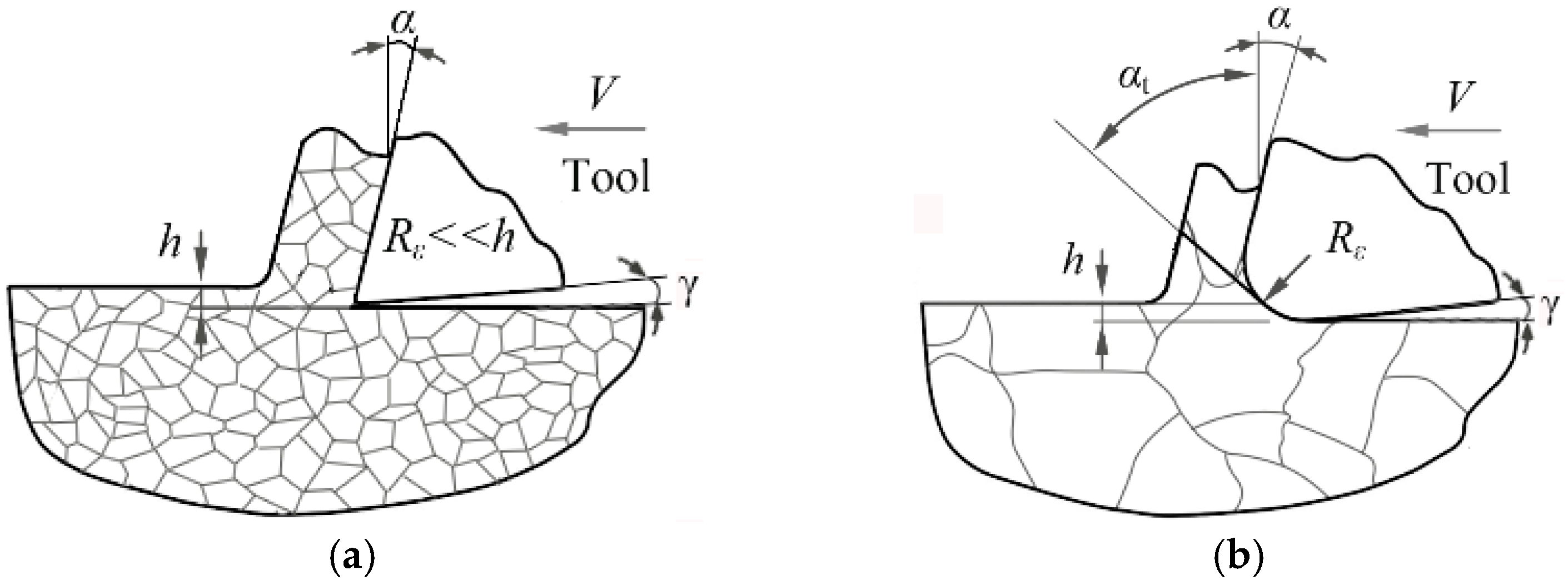
2. Methods
3. Simulation Results and Discussion
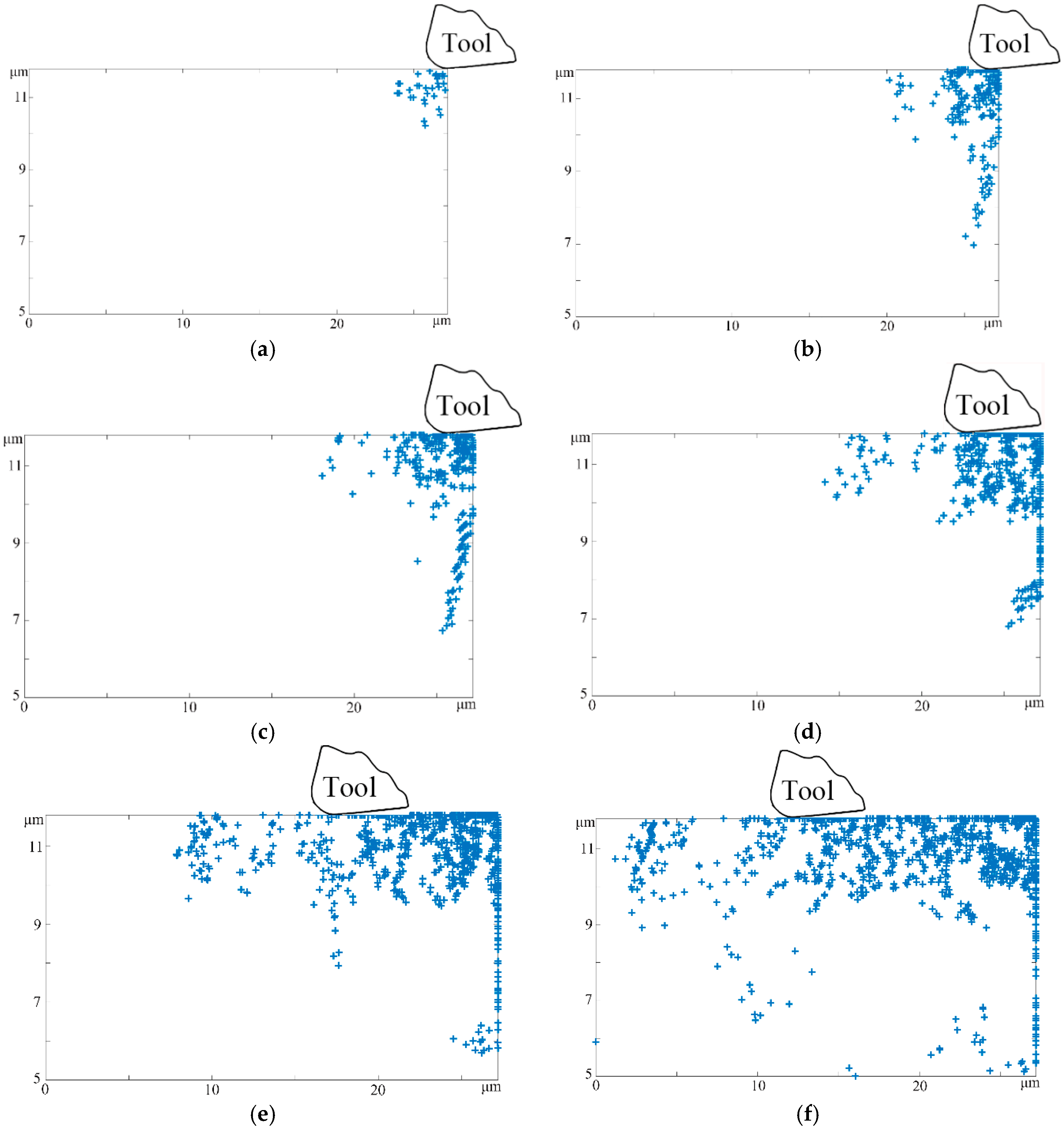
3.1. Influence of Cutting Distance on Subsurface Microstructure
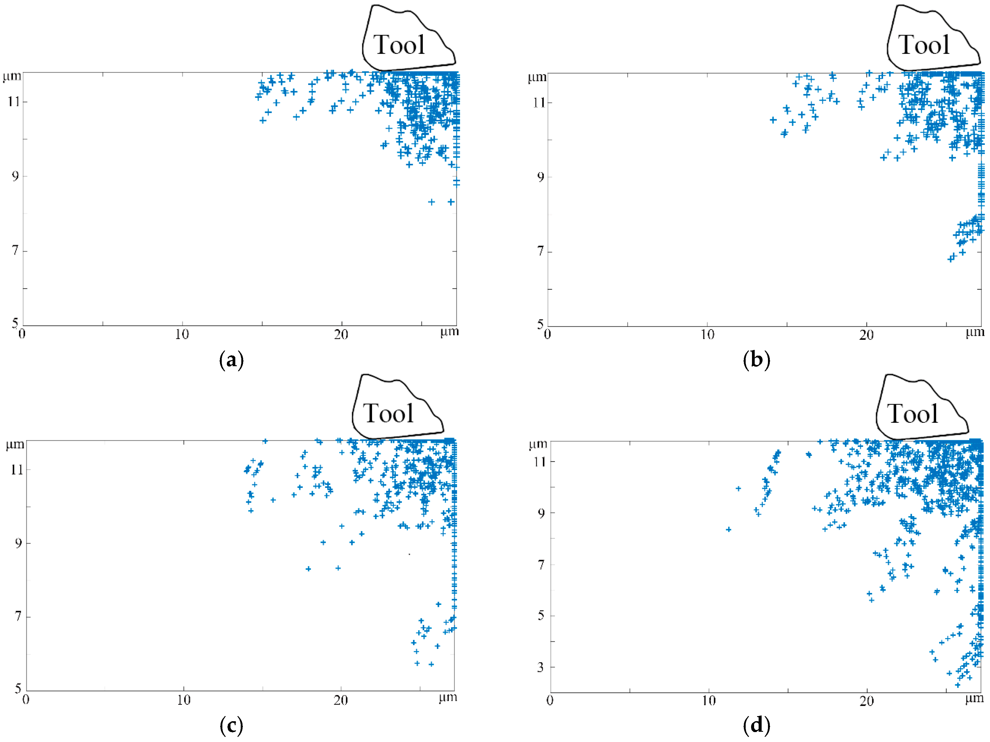
3.2. Influence of Tool Edge Radius on Subsurface Microstructure
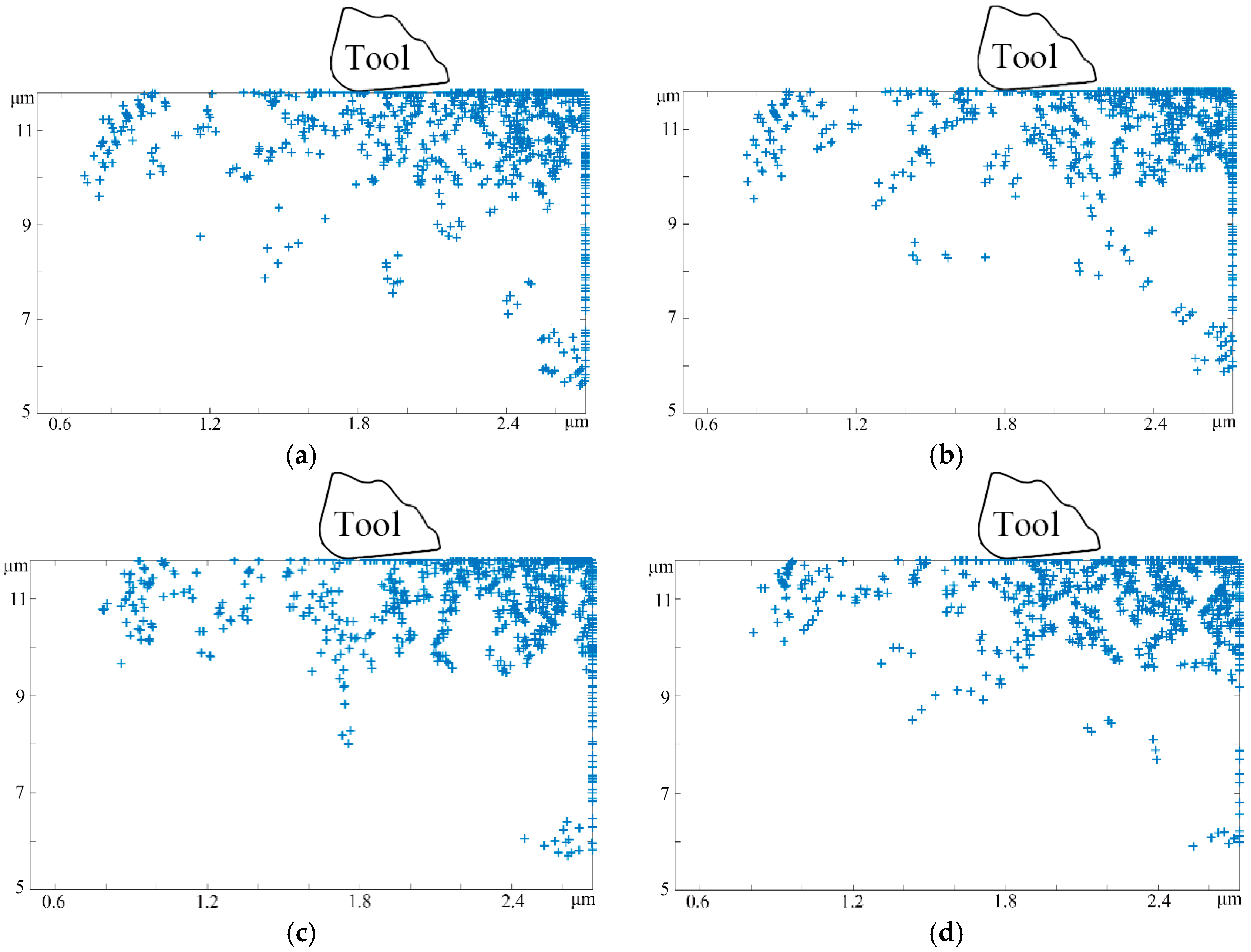
3.3. Influence of Tool Rake Angle on Subsurface Microstructure
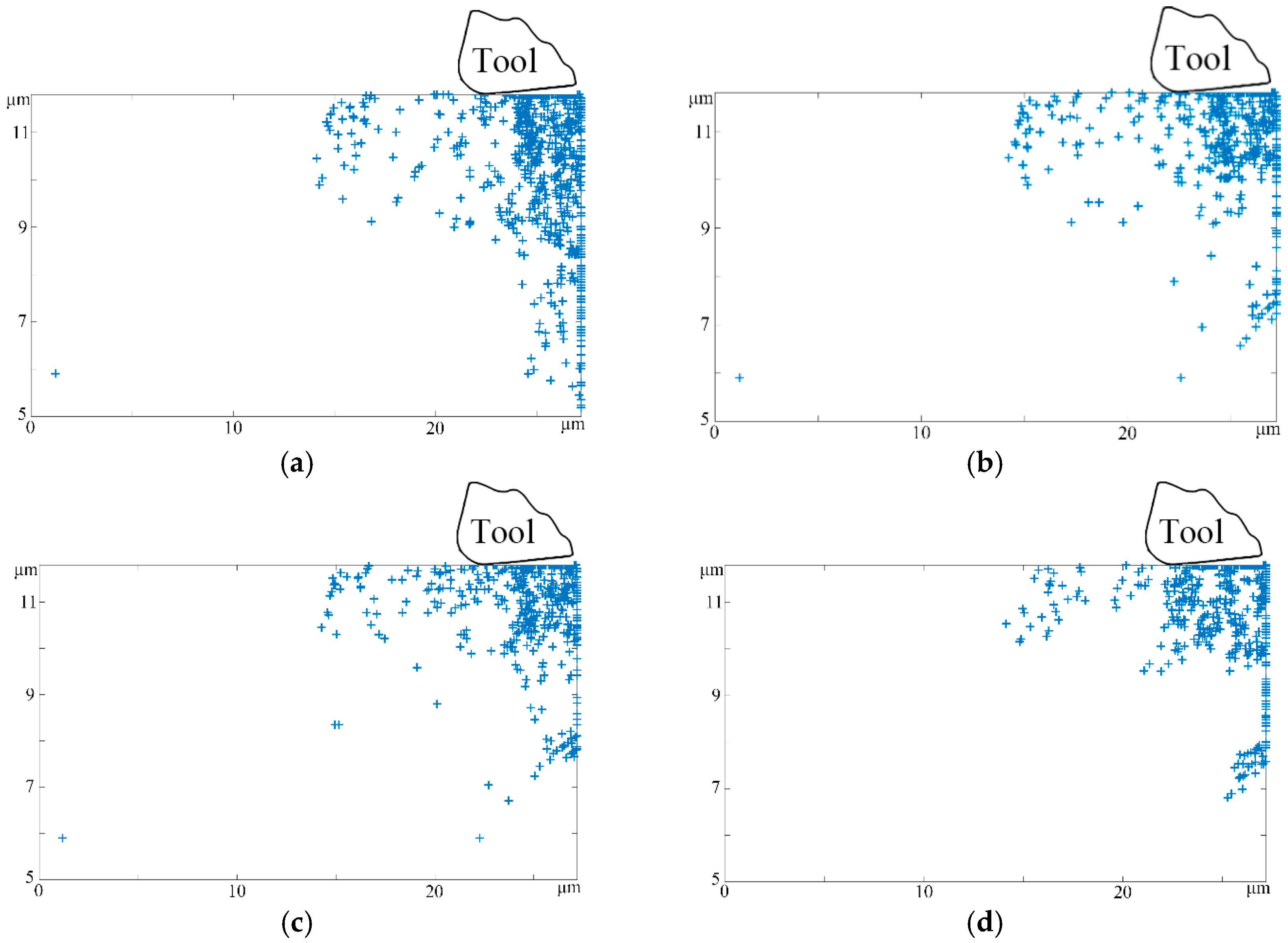
3.4. Influence of Clearance Angle on Subsurface Microstructure
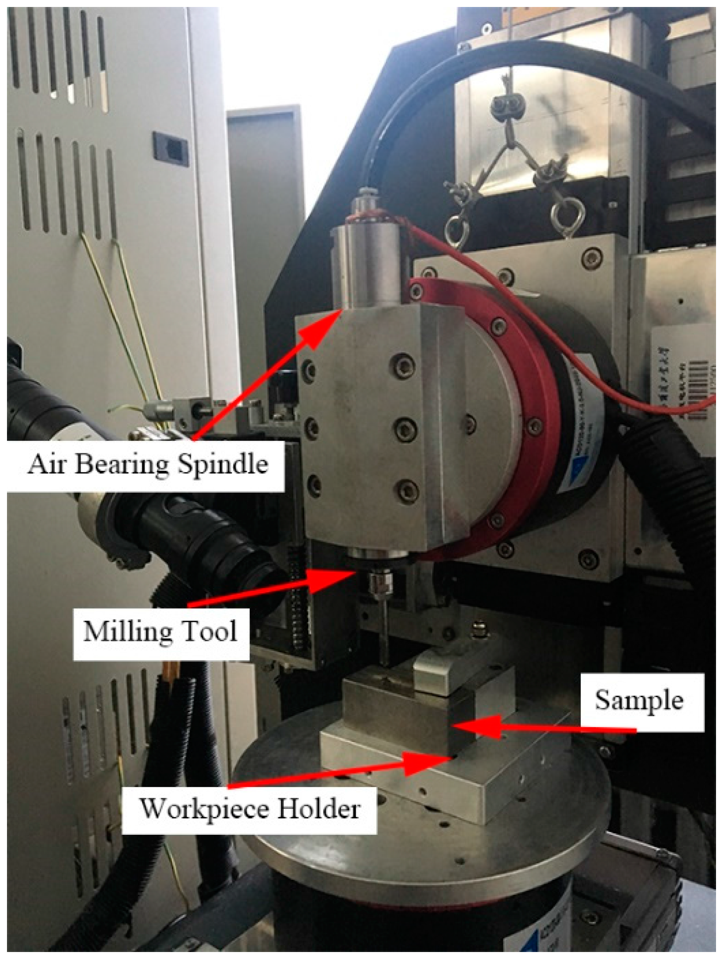
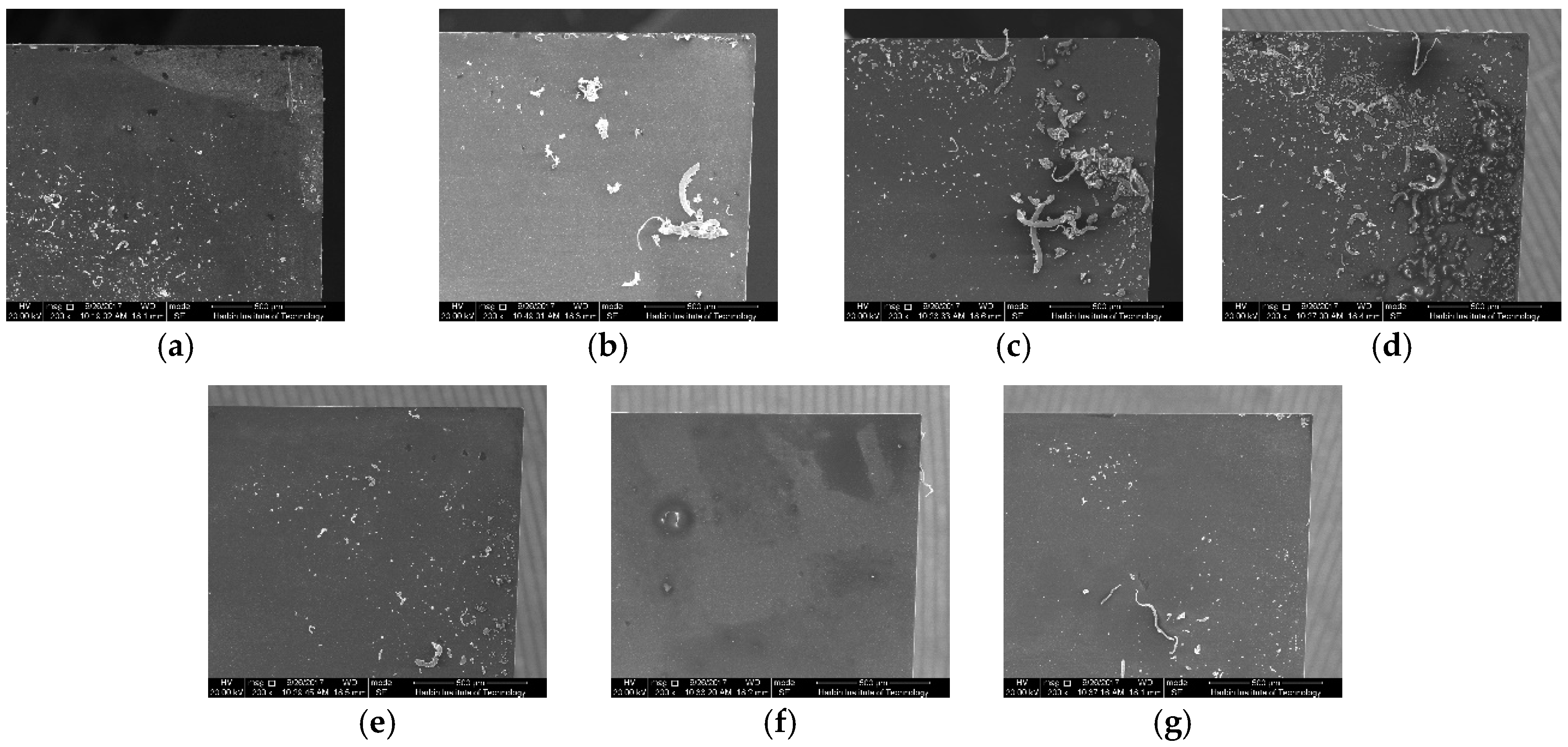
4. Experimental Results
5. Conclusions
- (a)
- In the process of micro-cutting, the dislocation multiplication, activity, pile-up, and annihilation resulted in many defects existing in the subsurface of the workpiece, such as discrete edge and screw dislocations, double cross-slip dislocations, parallel dislocation lines, intersection slip bands, vacancy defects, and refinement grains.
- (b)
- A reliable measurement method of the thickness of the subsurface damages layer was put forward during the micro-machining process. When the tool intrinsic parameters and processing conditions were kept constant, the depth of the subsurface damages layer increased significantly in the initial stage. Consequently, it would be maintained at a stable high-level because the dislocation nucleation and annihilation would make both ends meet in the stable removal phase.
- (c)
- Upon increasing the tool radius, the number of subsurface defects sharply increases beneath the cutting edge. Instead, the larger radius causes serious impact load and energy dissipation into the workpiece, which results in PSBs and the thermal activation dislocation of the core in the subsurface matrix material.
- (d)
- Increasing the tool rake angle greatly weakens the squeezing action between the tool and workpiece substrate, which eventually inhibits the energy consumption. In addition, although increasing the tool clearance angle significantly decreases the depth of the subsurface damages layer, it almost maintains a stable value if the clearance angle is greater than or equal to 5° in the cutting process of Ti-6Al-4V titanium alloy. Furthermore, the comparison between the predicted results and the experiment showed very good agreement.
Acknowledgments
Author Contributions
Conflicts of Interest
References
- Goel, S.; Luo, X.C.; Reuben, R.L. Wear mechanism of diamond tools against single crystal silicon in single point diamond turning process. Tribol. Int. 2013, 57, 272–281. [Google Scholar] [CrossRef]
- Attanasio, A. Tool run-out measurement in micro milling. Micromachines 2017, 8, 221. [Google Scholar] [CrossRef]
- Zhang, P.; Zhao, H.W.; Shi, C.L.; Zhang, L.; Huang, H.; Ren, L.Q. Influence of double-tip scratch and single-tip scratch on nano-scratching process via molecular dynamics simulation. Appl. Surf. Sci. 2013, 280, 751–756. [Google Scholar] [CrossRef]
- Wang, C.; Cheng, K.; Chen, X.; Minton, T.; Rakowski, R. Design of an instrumented smart cutting tool and its implementation and application perspectives. Smart Mater. Struct. 2014, 23, 035019. [Google Scholar] [CrossRef]
- Yao, C.F.; Wu, D.X.; Ma, L.; Tan, L.; Zhou, Z.; Zhang, J.Y. Surface integrity evolution and fatigue evaluation after milling mode, shot-peening and polishing mode for TB6 titanium alloy. Appl. Surf. Sci. 2016, 387, 1257–1264. [Google Scholar] [CrossRef]
- Ulutan, D.; Ozel, T. Machining induced surface integrity in titanium and nickel alloys: A review. Int. J. Mach. Tools Manuf. 2011, 51, 250–280. [Google Scholar] [CrossRef]
- Liu, Z.Q.; Xu, J.Y.; Han, S.; Chen, M. A coupling method of response surfaces (CRSM) for cutting parameters optimization in machining titanium alloy under minimum quantity lubrication (MQL) condition. Int. J. Precis. Eng. Manuf. 2013, 14, 693–702. [Google Scholar] [CrossRef]
- Wu, H.B.; Zhang, S.J. 3D FEM simulation of milling process for titanium alloy Ti6Al4V. Int. J. Adv. Manuf. Technol. 2014, 71, 1319–1326. [Google Scholar] [CrossRef]
- Bai, J.X.; Bai, Q.S.; Tong, Z.; Chao, H.; Wang, Y.X. Evolution of surface grain structure and mechanical properties in orthogonal cutting of titanium alloy. J. Mater. Res. 2016, 31, 3919–3929. [Google Scholar] [CrossRef]
- Pei, Q.X.; Lu, C.; Lee, H.P.; Zhang, Y.W. Study of materials deformation in nanometric cutting by large-scale molecular dynamics simulations. Nanoscale Res. Lett. 2009, 4, 444–451. [Google Scholar] [CrossRef] [PubMed]
- Che-Haron, C.H. Tool life and surface integrity in turning titanium alloy. J. Mater. Process. Technol. 2001, 118, 231–237. [Google Scholar] [CrossRef]
- Ginting, A.; Nouari, M. Surface integrity of dry machined titanium alloys. Int. J. Mach. Tools Manuf. 2009, 49, 325–332. [Google Scholar] [CrossRef]
- Thomas, M.; Turnerb, S.; Jackson, M. Microstructural damage during high-speed milling of titanium alloys. Scr. Mater. 2010, 62, 250–253. [Google Scholar] [CrossRef]
- Zhang, S.J.; To, S.; Cheung, C.F.; Zhu, Y. Micro-structural changes of Zn-Al alloy influencing micro-topographical surface in micro-cutting. Int. J. Adv. Manuf. Technol. 2014, 72, 9–15. [Google Scholar] [CrossRef]
- Huang, Y.H.; Zong, W.J. Molecular dynamic simulation for nanometric cutting of single-crystal face-centered cubic metals. Nanoscale Res. Lett. 2014, 9, 622. [Google Scholar] [CrossRef] [PubMed]
- Wang, Q.L.; Bai, Q.S.; Chen, J.X.; Su, H.; Wang, Z.G.; Xie, W.K. Influence of cutting parameters on the depth of subsurface deformed layer in nano-cutting process of single crystal copper. Nanoscale Res. Lett. 2015, 10, 396. [Google Scholar] [CrossRef] [PubMed]
- Wang, Q.L.; Bai, Q.S.; Chen, J.X.; Guo, Y.B.; Xie, W.K. Stress-induced formation mechanism of stacking fault tetrahedra in nano-cutting of single crystal copper. Appl. Surf. Sci. 2015, 355, 1153–1160. [Google Scholar] [CrossRef]
- Shishvan, S.S.; Van der Giessen, E. Mode I crack analysis in single crystals with anisotropic discrete dislocation plasticity: I. Formation and crack growth. Model. Simul. Mater. Sci. Eng. 2013, 21, 065006. [Google Scholar] [CrossRef]
- Wang, Q.Q.; Liu, Z.Q.; Wang, B.; Song, Q.H.; Wan, Y. Evolutions of grain size and micro-hardness during chip formation and machined surface generation for Ti-6Al-4V in high-speed machining. Int. J. Adv. Manuf. Technol. 2016, 82, 1725–1736. [Google Scholar] [CrossRef]
- Tarleton, E.; Balint, D.S.; Gong, J.; Wilkinson, A.J. A discrete dislocation plasticity study of the micro-cantilever size effect. Acta Mater. 2015, 88, 271–282. [Google Scholar] [CrossRef]
- Benzerga, A.A.; Brechet, Y.; Needleman, A.; Van der Giessen, E. Incorporating three-dimensional mechanisms into two-dimension dislocation dynamics. Model. Simul. Mater. Sci. Eng. 2004, 12, 159–196. [Google Scholar] [CrossRef]
- Benzerga, A.A. An analysis of exhaustion hardening in micro-scale plasticity. Int. J. Plasticity 2008, 24, 1128–1157. [Google Scholar] [CrossRef]
- Davoudi, K.M.; Nicola, L.; Vlassak, J.J. Dislocation climb in two-dimensional discrete dislocation dynamics. J. Appl. Phys. 2012, 111, 103522. [Google Scholar] [CrossRef]
- Jiang, B.; He, T.T.; Gu, Y.P.; Wang, Q.L.; Cao, L.G. Method for recognizing wave dynamics damage in high-speed milling cutter. Int. J. Adv. Manuf. Technol. 2017, 1, 1–12. [Google Scholar] [CrossRef]
- Tong, Z.; Luo, X.C. Investigation of focused ion beam induced damage in single crystal diamond tools. Appl. Surf. Sci. 2015, 347, 727–735. [Google Scholar] [CrossRef]
- Tong, Z.; Luo, X.C.; Sun, J.N.; Liang, Y.C.; Jiang, X.Q. Investigation of a scale-up manufacturing approach for nanostructures by using a nanoscale multi-tip diamond tool. Int. J. Adv. Manuf. Technol. 2015, 80, 699–710. [Google Scholar] [CrossRef]


| Contact Parameters | Value |
|---|---|
| Heat transfer coefficient (W/m2·K) | 4 × 10⁴ |
| Heat partition coefficient | 0.5 |
| Friction coefficient | 0.7 |
| Friction energy transferred into heat | 100% |
| Acronyms | Description |
|---|---|
| DD | Dislocation dynamics |
| SSDs | Subsurface damages |
| MD | Molecular dynamics |
| FE | Finite element |
| F-R | Frank–Read |
| P-K | Peach-Koehler |
| PCD | Polycrystalline diamond |
| Test No. | Tool Diameter (mm) | Cutting Edge Radius (μm) | Rake Angle (°) | Clearance Angle (°) | Surface Roughness (nm) |
|---|---|---|---|---|---|
| 1 | 4.5 | 20 | 5 | 15 | 70.6 |
| 2 | 4.5 | 30 | 5 | 15 | 103.9 |
| 3 | 4.5 | 40 | 5 | 15 | 121.9 |
| 4 | 4.5 | 20 | 3 | 15 | 88.7 |
| 5 | 4.5 | 20 | 1 | 15 | 104.2 |
| 6 | 4.5 | 20 | 5 | 8 | 77.8 |
| 7 | 4.5 | 20 | 5 | 5 | 93.3 |
© 2017 by the authors. Licensee MDPI, Basel, Switzerland. This article is an open access article distributed under the terms and conditions of the Creative Commons Attribution (CC BY) license (http://creativecommons.org/licenses/by/4.0/).
Share and Cite
Bai, J.; Bai, Q.; Tong, Z. Dislocation Dynamics-Based Modeling and Simulations of Subsurface Damages Microstructure of Orthogonal Cutting of Titanium Alloy. Micromachines 2017, 8, 309. https://doi.org/10.3390/mi8100309
Bai J, Bai Q, Tong Z. Dislocation Dynamics-Based Modeling and Simulations of Subsurface Damages Microstructure of Orthogonal Cutting of Titanium Alloy. Micromachines. 2017; 8(10):309. https://doi.org/10.3390/mi8100309
Chicago/Turabian StyleBai, Jinxuan, Qingshun Bai, and Zhen Tong. 2017. "Dislocation Dynamics-Based Modeling and Simulations of Subsurface Damages Microstructure of Orthogonal Cutting of Titanium Alloy" Micromachines 8, no. 10: 309. https://doi.org/10.3390/mi8100309
APA StyleBai, J., Bai, Q., & Tong, Z. (2017). Dislocation Dynamics-Based Modeling and Simulations of Subsurface Damages Microstructure of Orthogonal Cutting of Titanium Alloy. Micromachines, 8(10), 309. https://doi.org/10.3390/mi8100309