1. Introduction
As one of the most promising droplet-actuation technologies, electrowetting-on-dielectric (EWOD), is considered one of most promising tools to realize lab-on-a-chip (LOC) devices by building digital microfluidics platforms for chemical and biological detections. EWOD actuation is induced by the electrowetting phenomenon that wetting can be effectively controlled by an electric field [
1,
2,
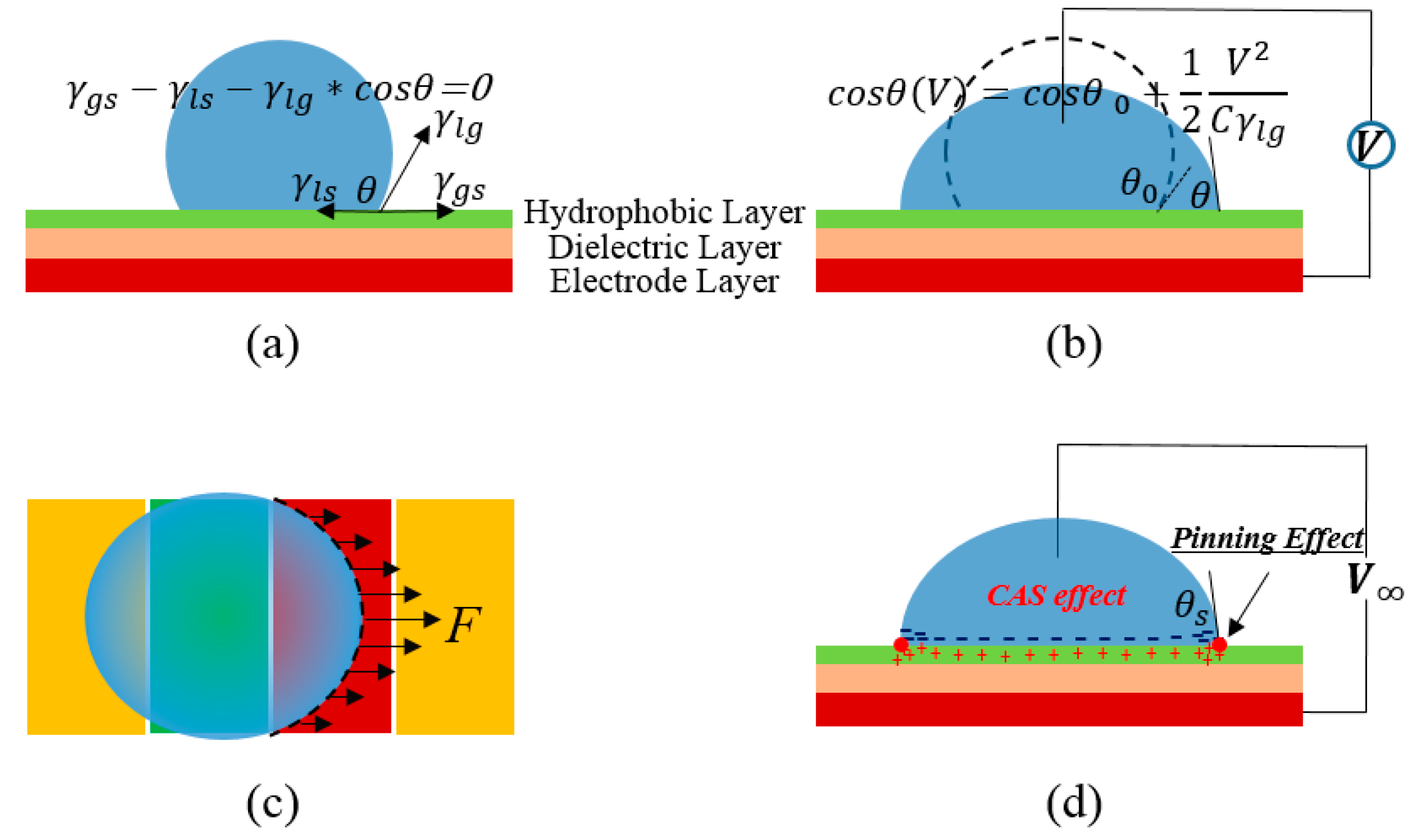
3]. The wetting is generally characterized by contact angle, and from its change the electrowetting force is born, as shown in
Figure 1a,b.
Figure 1c indicates the driving force on a droplet generated by the surface tension on the contact line. The traditional scheme of EWOD implies a droplet lying on a metal substrate, covered by dielectric material and Teflon hydrophobic surface, and inserted with a metal line on the top, as shown in
Figure 1b.
Recently, a rapid growth in EWOD-based microfluidic systems has been seen with many biological applications, such as DNA enrichment [
4] and ligation [
5], enzyme assays [
6,
7,
8], cell-based assays [
9], polymerase chain reaction (PCR) [
10], and proteomics [
11,
12,
13,
14]. At the same time, the fundamentals of electrowetting have remained not fully understood.
Figure 1d represents the contact angle saturation phenomenon and pinning effect, and the explanations of them are very different and highly debatable [
15,
16,
17]. The dynamic saturation phenomenon, that droplet velocity would be limited by a saturated value, is still imperfectly explained [
18,
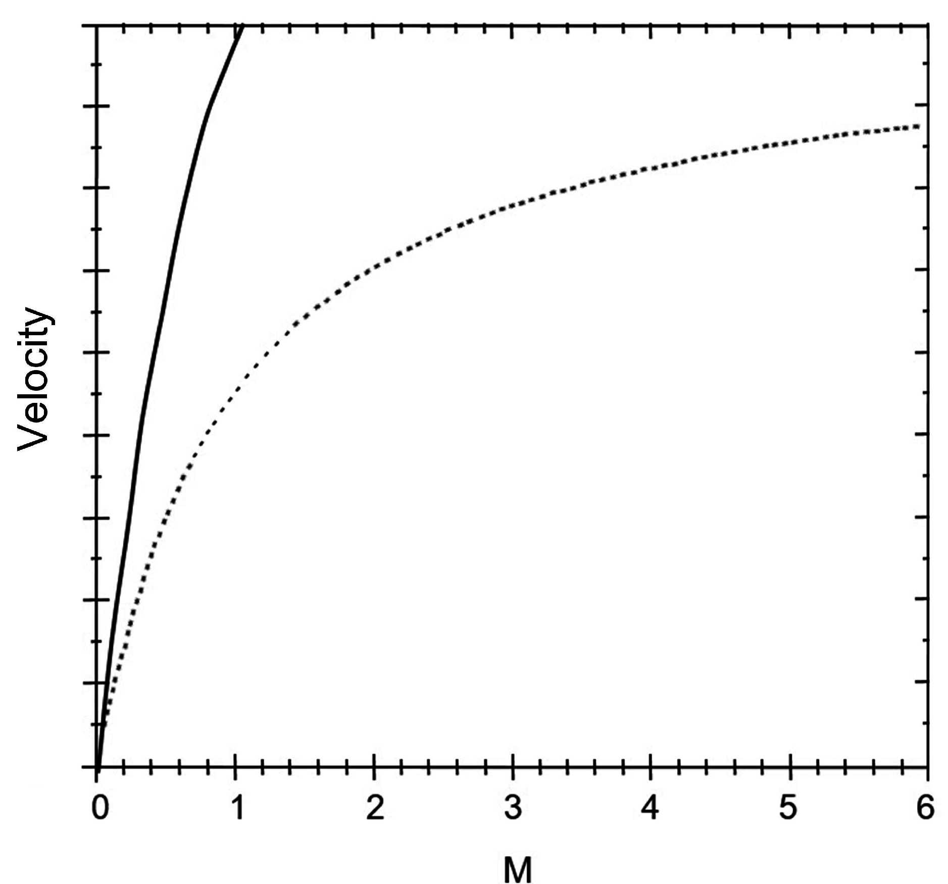
19]. The developed dynamic models, represented by Brochard’s theoretical model, cannot predict the dynamic saturation phenomenon (
Figure 2). In the present paper, a dynamic saturation model of droplets transported on a single-plate EWOD device, from the common-sense electrowetting theories, such as Lippmann equation and three-contact-line theory, is derived.
Additionally, the contact angle saturation is treated with a double-layer capacitance-based electric circuit to further understand the dynamic saturation phenomenon.
Figure 1.
Schematics of (a) surface tensions on the tri-line interface of droplet on an electrowetting-on-dielectric (EWOD) device; (b) the electrowetting principle; (c) driving force derived from integration of the surface tension in contacting line; and (d) static effects on the droplet including the contact angle saturation (CAS) effect and pinning effect. The surface tensions in (c) represent the component in the driving direction. Furthermore, θS in (d) stands for the saturated contact angle when the applied voltage is large enough.
Figure 2.
Comparison of curves induced by Brochard’s theoretical model (solid line) and the saturation phenomenon found in experiments (dashed one), which indicates that the dynamic saturation effect cannot be predicted by Brochard’s model.
Figure 2.
Comparison of curves induced by Brochard’s theoretical model (solid line) and the saturation phenomenon found in experiments (dashed one), which indicates that the dynamic saturation effect cannot be predicted by Brochard’s model.
2. Dynamic Saturation Model of Droplet Motion on the Open DMF Chip
The derivation of this model is based on the analysis of the kinetic equilibrium between driving force and damp effects, and droplet deformation,
t, is taken into account. The influences of pining effect and errors caused by the droplet deformation, contact line length variation, and velocity measuring method have been carefully considered. The modeling process and details are presented in the
supplement. Equation (1) presents the mathematical expression of the velocity of electrowetting droplet motion on the open digital microfluidics (DMF) chip.
where
d is the thickness of the dielectric layer. ε
r and ε are the relative permittivity of the dielectric and the vacuum permittivity, respectively. The hysteresis effect [
20,
21] in the EWOD surface should be taken into account, which is assumed to be a constant
∆f.
l represents the effective contact line length, and
R is the droplet radium.
K1,
Kc, and
CV, respectively, stand for the factor induced by the droplet acceleration and deceleration process, the pinning effect in the triangle region, and the viscous damp from the area on the chip the droplet covers. This model indicates the relationship between droplet motion dynamics and the device physics including device structure properties (
d, ε
r, and
l), hydrophobic surface (γ, ∆
f, and
CV), and interface electronics (
Kc). The consideration of these properties is presented in
the supplementary information.
Figure 3 shows the droplet velocity curve plotted based on the dynamic saturation model. Wherein, the black dots represent the reported experimental data from reference [
19]. The validity of the dynamic model is limited to a certain value of the system parameters, which is influenced by the device properties. The mismatch at low voltages mainly comes from the difficulty of estimating the parameters of the DMF chip used in reference, especially ones related to the hydrophobic surface properties.
Figure 3.
Comparison between the dynamic saturation model (line) and experiment results in reference [
20] (plots). The red curve is induced by Equation (1) and its modification, taking the radium variation into account, is represented by the blue curve.
Figure 3.
Comparison between the dynamic saturation model (line) and experiment results in reference [
20] (plots). The red curve is induced by Equation (1) and its modification, taking the radium variation into account, is represented by the blue curve.
Compared with the conventional dynamic model of electrowetting droplet motion, Equation (1) represents a novel expression of the dynamic properties of droplets motion on DMF chips. It is clear that the role of could be neglected when the applied voltage is high enough. Thus, the droplet velocity is independent from the voltage. In other words, the saturated velocity of the droplet is determined by the parameters of the DMF system, including the EWOD device and the droplet itself. Furthermore, it suggests the importance of designing the EWOD device and controlling the droplet carefully to obtain the optimized actuation effect.
Finally, the dynamic model developed in this paper provides one explanation of the dynamic saturation phenomenon. The basic view of this model can be summarized as the following. The electrowetting force increases with the applied voltage, and at the same time the damping force will get larger as a result of the enlargement of the wetted surface. Both of these inverse effects are generated by the electrowetting force; finally, the dynamic saturation occurs as a compromise between them.
3. Influence of Device Physics on the Dynamics of Droplet Motion
For a better understanding of the dynamic saturation model, the parameters in the model are discussed in the following. In the discussion, the role of the electrowetting number is redefined. The influence of structure parameters, such as dielectric thickness, permittivity and contact angle are presented in detail from the view of device physics. The hydrophobic surface properties and interface electronics in the triple line are also concluded. All the above discussions are based on Equation (1), neglecting the droplet radium variation for simplicity.
3.1. Electrowetting Number, M
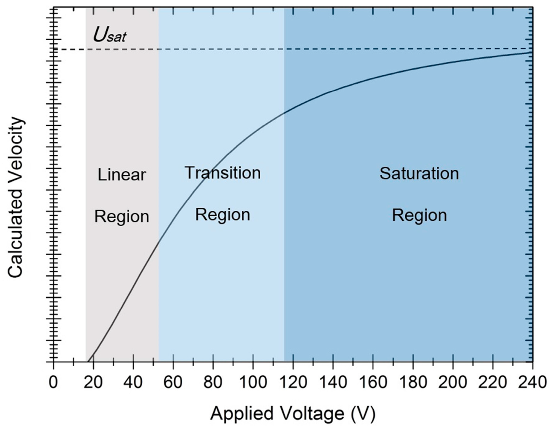
The relationship between droplet velocity and the applied voltage is plotted in
Figure 4. For a better understanding, the dynamic process is divided into linear, transition, and saturation regions, according to the applicability of the traditional Lippmann static laws. Especially, the electrowetting number
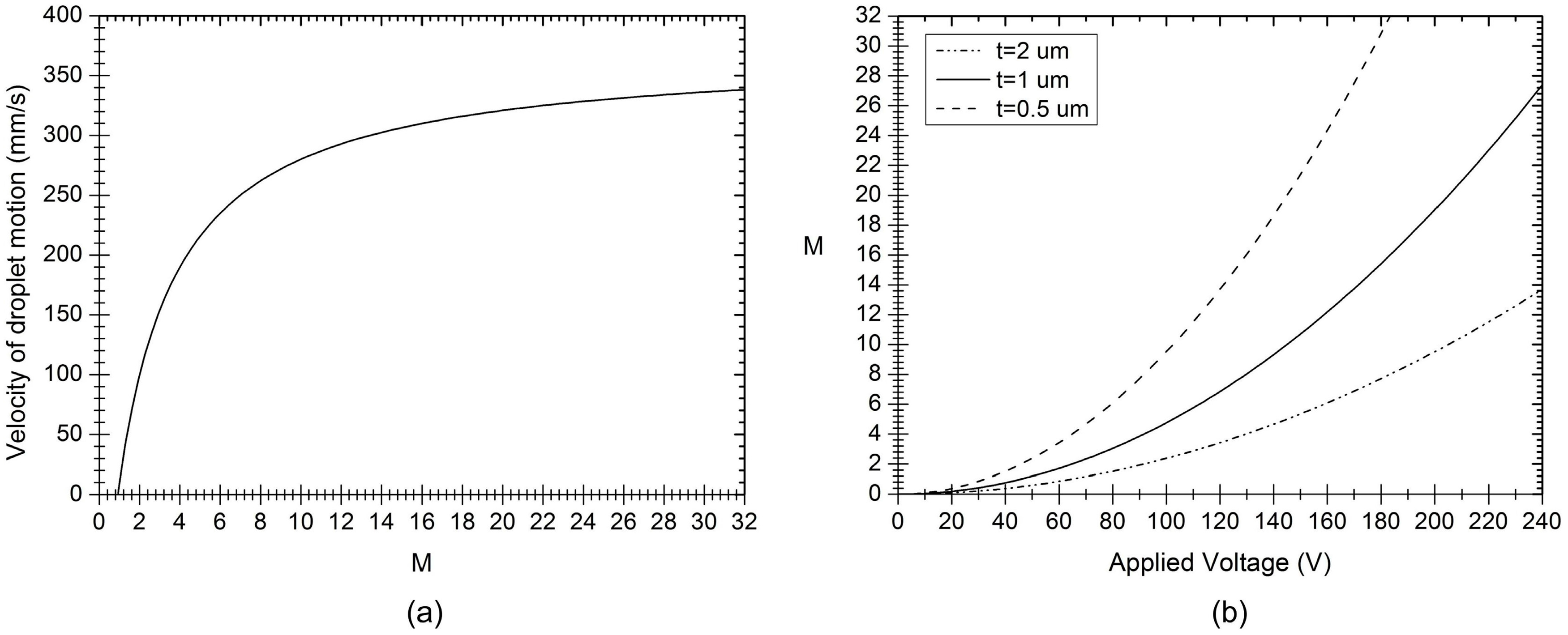
is redefined as the measure of the dynamic saturation model. The calculated velocity of the droplet as a function of
M is plotted in
Figure 5a. When
M is very small, the dynamic properties keep consistent with the Lippmann static laws. However, when
M is great enough, the dynamic properties fit with the saturation region. The process between the linear and saturation is the transition region, where the saturation effect comes to influence the velocity curve. The relationship between the electrowetting number and the applied voltage is presented in
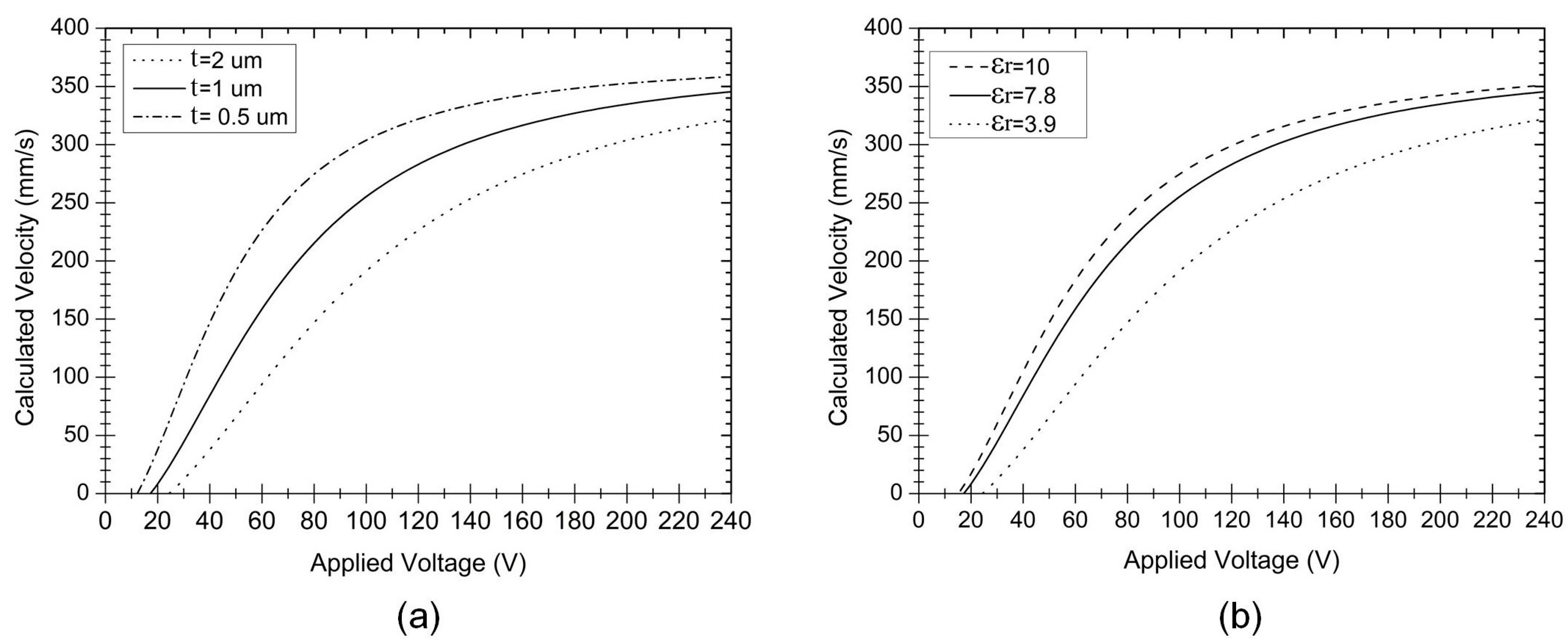
Figure 5b. For thinner dielectric layers,
M is larger with the same voltage and thus the electrowetting process is more effective. In this way, the sensitivity of
M to applied voltage determines the EWOD actuation efficiency.
Figure 5.
(a) Velocity of droplet motion as a function of the electrowetting number, M; and (b) the electrowetting number varies with the applied voltage.
Figure 5.
(a) Velocity of droplet motion as a function of the electrowetting number, M; and (b) the electrowetting number varies with the applied voltage.
3.3. Super-Hydrophobic Surface
As much attention focuses on the improvement of the hydrophobic surface, different materials with super-hydrophobic features have been utilized to replace traditional hydrophobic materials [
27,
28,
29,
30]. For the purpose of droplet operations, the super-hydrophobic surface should satisfy the Cassie state, wherein the damp force and hysteresis effect are reduced dramatically. Experiments of super-hydrophobic materials have been presented to satisfy the condition for improved electrowetting applications [
27,
31,
32,
33]. Therefore, the model of super-hydrophobic surface discussed here is only suitable for the Cassie case. To adjust the analysis of these applications, the initial contact angle is treated to be variable in the modeling. Following the same modeling process, the relationship between initial contact angle θ
0 and droplet velocity
U is obtained:
where, ∆
f is neglected due to the very low hysteresis effect of the super-hydrophobic surface.
The droplet velocity
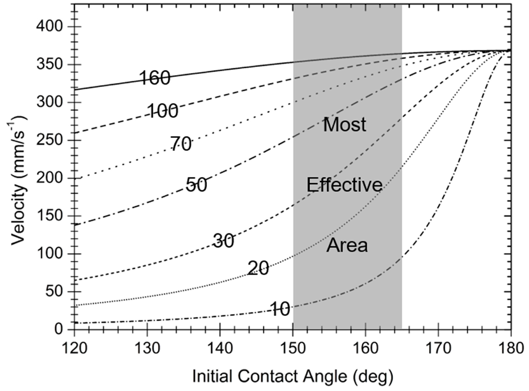
U, as a function of the initial contact angle from 120° to 180°, is plotted in
Figure 7. For the same applied voltage, the droplet velocity increases with larger initial contact angles,
i.e., with more hydrophobic surfaces. Especially in the region from 150° to 165°, the droplet velocity changes violently with applied voltage. This region is “the most effective area”, as
Figure 7 shows, where a narrow voltage range can be used to achieve the same modulation of the droplet velocity. The different curves in
Figure 7 converge to the same point, which indicates that the saturation droplet velocity is independent of the initial contact angle.
Figure 7.
Effect of a droplet’s initial contact angle on velocity, according to Equation (2). The initial contact angle is determined by the surface property of the EWOD device. The applied voltages, respectively, are 10, 20, 30, 50, 70, and 160 V from bottom to top. For the range from 150° to 165°, the velocity increases more rapidly with the applied voltage; therefore, this range is “the most effective area” to convert electric energy into droplet kinetic energy. When the applied voltage is greater than 160 V, the saturation velocity is independent with the initial contact angle.
3.4. Influence of Interface Electronics and Contact Angle Saturation Effect
The above works are carried out based on the dynamic equilibrium between electrowetting force and the damping force on the droplet. By taking into account the droplet deformation, a dynamic model of droplet motion on a single-plate EWOD device was induced, which fits well with the dynamic saturation phenomenon. Contact angle saturation is thought to be one cause of dynamic saturation, but it has not been considered during this modeling due to the difficulty of describing it mathematically. Many models or hypotheses have been proposed to explain the contact angle saturation, as reviewed by Mugele [
34], Chevalliot
et al. [
15], Koopal [
16] and Sedev [
35], as well as, more recently, by Chevalliot
et al. [
15]. These theories or hypotheses can be briefly summarized as dielectric breakdown, zero interfacial tension, contact line instability, gas ionization or insulating fluid charging, minimization of the electrostatic energy, and Tailor cone. At present, the formation of contact angle saturation remains unclear and it is difficult to describe it quantitatively. In reference [
15], it has been experimentally demonstrated that contact angle saturation is invariant with numerous variables, including dielectric thickness, interfacial tension, and the chemical properties of the droplet, such as pH, ion type/size, and solute/solvent interaction. Here, a trial is made to treat this well-known but not well-understood effect as one factor and discuss its influence on this model.
A generalized Lippmann Equation was derived from the first principles as the following [
36]:
where
C is the capacitance of the Helmholtz double layer at the interface between droplet and EWOD substrate.
S is the wetted solid area, and
.
a is the radium of the wetted area.
As discussed in reference [
34], the well-known Lippmann equation is a particular case of electrowetting when the radial derivative of the capacitance of the double layer is constant. This is similar to the situation where the Lippmann static law is applicable only when the applied voltage is low. This work has demonstrated that the contact angle of electrowetting depends on the gradient of capacitance of the double layer in the vicinity of the triple line, which is thought to be dependent on the distribution of the accumulated charges [
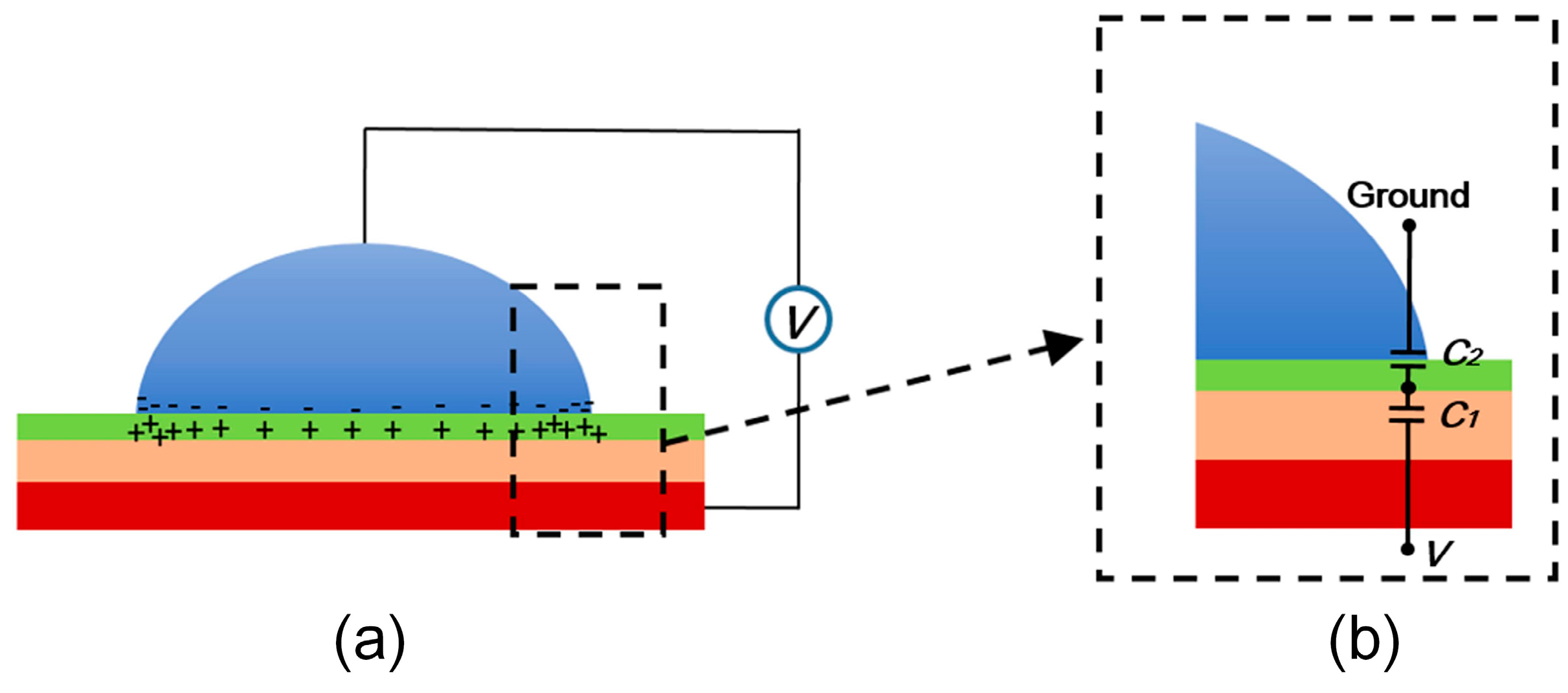
16], as shown in
Figure 8a.
Figure 8.
(a) Charges distribution on the liquid–solid interface and (b) the equivalent electric circuit of the triangle line region. C1 is the capacitance of dielectric layer, and C2 is the capacitance of the double layer that is determined by the accumulated charges distribution.
Figure 8.
(a) Charges distribution on the liquid–solid interface and (b) the equivalent electric circuit of the triangle line region. C1 is the capacitance of dielectric layer, and C2 is the capacitance of the double layer that is determined by the accumulated charges distribution.
For a better description of the capacitance distribution in the triple line, an equilibrium electric model is built, as shown in
Figure 8b.
When the voltage is applied, the capacitances are charged. More charges will accumulate in the triple line area due to its spiky shape, resulting in a stronger capacitance in this location than other wetted areas [
1]. The fact that the triple line is usually de-pinned in the electrowetting and EWOD actuation experiments is evidence of this [
2]. By analyzing the electric model in
Figure 8b, the effective voltage applied on the triple line is obtained:
The electric energy working on the triple line region is:
With the applied voltage increasing, more charges accumulate in the triple line region. Furthermore, the value of C2 would get larger due to the fact that the double layer would get thinner. While the capacitance, C1, induced by the dielectric layer remains constant. Thus, the increase of effective voltage cannot keep pace with the applied voltage due to the decrease of the transfer coefficient. There should exist one point beyond which the effective voltage becomes independent of the applied voltage. At this time, the voltage working on the electrowetting system keeps constant. From Equation (5), the effective electric energy working on the triple line region varies in a similar way. As the applied voltage increases and the transfer coefficient decreases, the value of E would become invariable when the well-known contact angle saturation occurs. Meanwhile, the accumulated charges in the triple line region would probably enhance the pinning effect, which helps to increase the damp force on the droplet.
Contact angle saturation effect is another crucial cause of the dynamic saturation, as a limited electric energy effectively works on the triple line region. When the effective electric energy in the triple line region is limited, the electrowetting force will be limited, and the droplet deformation induced by the electric field will be suspended. Thus, it can be thought that the contact angle saturation accelerates the dynamic saturation in the transition region and, finally, ends the dynamic process by limiting the electrowetting force.
4. Conclusions
In summary, a dynamic saturation model of electrowetting droplet motion on the open DMF system is presented in this work. On the basis of the present analysis, the dynamic saturation phenomenon is primarily a consequence of dynamic equilibrium between driving force and damp effects, and the contact angle saturation effect. Among them, dynamic equilibrium forms the configuration of the velocity curve as a function of applied voltage. Meanwhile, contact angle saturation accelerates the saturation process by limiting the electrowetting force with a finite value, which confines the translation of the electronic energy to the mechanical energy of the droplet. The influence of device physics, including electrode formation, dielectric layer, hydrophobic surface and interface conditions, have been discussed based on this model, which fit well with reported methods to improve electrowetting induced droplet motions. Specifically, the saturated velocity is independent of the dielectric thickness, as well as the permittivity. Meanwhile, a dielectric layer of thinner thickness and higher permittivity contributes to more effective actuation and lower threshold voltage. The “most effective area” of initial contact angle using super-hydrophobic surface materials or structures helps to optimize the hydrophobic surface. This study helps to deeper understand electrowetting, and shows practical value for further optimizing EWOD devices.
Acknowledgments
This work was supported by Natural Science Foundation of China (NSFC No. 51375341), the Program of Introducing Talents of Discipline to Universities (111 project No. B07014) and the National High Technology Research and Development Program of China (863 Program No.2015AA042603).
Author Contributions
Weiwei Cui, Hao Zhang and Wei Pang proposed the idea; Weiwei Cui and Menglun Zhang performed the model derivation; Weiwei Cui and Hao Zhang prepared the manuscript; Xuexin Duan and Daihua Zhang contributed to the discussion and gave valuable suggestions on the manuscript revision according to the referee report.
Conflicts of Interest
The authors declare no conflict of interest.
References
- Lippmann, G. Relations entre les phénomènes électriques et capillaires. Ann. Chim. Phys. 1875, 5, 494. [Google Scholar]
- Hayes, R.A.; Feenstra, B.J. Video-speed electronic paper based on electrowetting. Nature 2003, 425, 383–385. [Google Scholar] [CrossRef] [PubMed]
- Mugele, F.; Baret, J.C. Electrowetting: From basics to applications. J. Phys. Condens. Matter 2005, 17, R705. [Google Scholar] [CrossRef]
- Abdelgawad, M.; Freire, S.L.S.; Yang, H.; Wheeler, A.R. All-terrain droplet actuation. Lab Chip 2008, 8, 672–677. [Google Scholar] [CrossRef] [PubMed]
- Liu, Y.J.; Yao, D.J.; Lin, H.C.; Chang, W.-Y.; Chang, H.-Y. DNA ligation of ultramicro volume using an EWOD microfluidic system with coplanar electrodes. J. Micromech. Microeng. 2008, 18, 045017. [Google Scholar] [CrossRef]
- Srinivasan, V.; Pamula, V.K.; Fair, R.B. An integrated digital microfluidic lab-on-a-chip for clinical diagnostics on human physiological fluids. Lab Chip 2004, 4, 310–315. [Google Scholar] [CrossRef] [PubMed]
- Taniguchi, T.; Torii, T.; Higuchi, T. Chemical reactions in microdroplets by electrostatic manipulation of droplets in liquid media. Lab Chip 2002, 2, 19–23. [Google Scholar] [CrossRef] [PubMed]
- Miller, E.M.; Wheeler, A.R. A digital microfluidic approach to homogeneous enzyme assays. Anal. Chem. 2008, 80, 1614–1619. [Google Scholar] [CrossRef] [PubMed]
- Barbulovic-Nad, I.; Yang, H.; Park, P.S.; Wheeler, A.R. Digital microfluidics for cell-based assays. Lab Chip 2008, 8, 519–526. [Google Scholar] [CrossRef] [PubMed]
- Chang, Y.H.; Lee, G.B.; Huang, F.C.; Chen, Y.Y.; Lin, J.L. Integrated polymerase chain reaction chips utilizing digital microfluidics. Biomed. Microdevices 2006, 8, 215–225. [Google Scholar] [CrossRef] [PubMed]
- Moon, H.; Wheeler, A.R.; Garrell, R.L.; Loo, J.A.; Kim, C.J. An integrated digital microfluidic chip for multiplexed proteomic sample preparation and analysis by MALDI-MS. Lab Chip 2006, 6, 1213–1219. [Google Scholar] [CrossRef] [PubMed]
- Wheeler, A.R.; Moon, H.; Bird, C.A.; Loo, R.R.; Kim, C.J.; Loo, J.A.; Garrell, R.L. Digital microfluidics with in-line sample purification for proteomics analyses with MALDI-MS. Anal. Chem. 2005, 77, 534–540. [Google Scholar] [CrossRef] [PubMed]
- Wheeler, A.R.; Moon, H.; Kim, C.J.; Loo, J.A.; Garrell, R.L. Electrowetting-based microfluidics for analysis of peptides and proteins by matrix-assisted laser desorption/ionization mass spectrometry. Anal. Chem. 2004, 76, 4833–4838. [Google Scholar] [CrossRef] [PubMed]
- Luk, V.N.; Mo, G.C.H.; Wheeler, A.R. Pluronic additives: A solution to sticky problems in digital microfluidics. Langmuir 2008, 24, 6382–6389. [Google Scholar] [CrossRef] [PubMed]
- Chevalliot, S.; Kuiper, S.; Heikenfeld, J. Experimental validation of the invariance of electrowetting contact angle saturation. J. Adhes. Sci. Technol. 2012, 26, 1909–1930. [Google Scholar] [CrossRef]
- Koopal, L.K. Wetting of solid surfaces: Fundamentals and charge effects. Adv. Colloid Interface Sci. 2012, 179, 29–42. [Google Scholar] [CrossRef] [PubMed]
- Chen, L.; Bonaccurso, E. Electrowetting—From statics to dynamics. Adv. Colloid Interface Sci. 2014, 210, 2–12. [Google Scholar] [CrossRef] [PubMed]
- Wang, K.L.; Jones, T.B. Saturation effects in dynamic electrowetting. Appl. Phys. Lett. 2005, 86, 054104. [Google Scholar] [CrossRef]
- Bavière, R.; Boutet, J.; Fouillet, Y. Dynamics of droplet transport induced by electrowetting actuation. Microfluid. Nanofluid. 2008, 4, 287–294. [Google Scholar] [CrossRef]
- Yeo, L.Y.; Chang, H.C. Static and spontaneous electrowetting. Mod. Phys. Lett. B 2005, 19, 549–569. [Google Scholar] [CrossRef]
- Gupta, R.; Sheth, D.M.; Boone, T.K.; Sevilla, A.B.; Fréchette, J. Impact of pinning of the triple contact line on electrowetting performance. Langmuir 2011, 27, 14923–14929. [Google Scholar] [CrossRef] [PubMed]
- Moon, H.; Cho, S.K.; Garrell, R.L. Low voltage electrowetting-on-dielectric. J. Appl. Phys. 2002, 92, 4080–4087. [Google Scholar] [CrossRef]
- Chang, J.; Choi, D.Y.; Han, S.; Pak, J.J. Driving characteristics of the electrowetting-on-dielectric device using atomic-layer-deposited aluminum oxide as the dielectric. Microfluidi. Nanofluid. 2010, 8, 269–273. [Google Scholar] [CrossRef]
- Berthier, J.; Peponnet, C. A model for the determination of the dimensions of dents for jagged electrodes in electrowetting on dielectric microsystems. Biomicrofluidics 2007, 1, 014104. [Google Scholar] [CrossRef] [PubMed]
- Chen, J.; Yu, Y.; Li, J.; Lai, Y.; Zhou, J. Size-variable droplet actuation by interdigitated electrowetting electrode. Appl. Phys. Lett. 2012, 101, 234102. [Google Scholar] [CrossRef]
- Pyne, D.G.; Salman, W.M.; Abdelgawad, M.; Sun, Y. Partially filled electrodes for digital microfluidic devices. Appl. Phys. Lett. 2013, 103, 024103. [Google Scholar] [CrossRef]
- Accardo, A.; Mecarini, F.; Leoncini, M.; Brandi, F.; Di Cola, E.; Burghammer, M.; Riekel, C.; Di Fabrizio, E. Fast, active droplet interaction: Coalescence and reactive mixing controlled by electrowetting on a superhydrophobic surface. Lab Chip 2013, 13, 332–335. [Google Scholar] [CrossRef] [PubMed]
- Hill, R.M. Superhydrophobic surfaces. Curr. Opin. Colloid Interface Sci. 2006, 11, 193–202. [Google Scholar]
- Vasudev, A.; Jagtiani, A.; Du, L.; Zhe, J. A low-voltage droplet microgripper for micro-object manipulation. J. Micromech. Microeng. 2009, 19, 075005. [Google Scholar] [CrossRef]
- Sen, P.; Kim, C.J. Capillary spreading dynamics of electrowetted sessile droplets in air. Langmuir 2009, 25, 4302–4305. [Google Scholar] [CrossRef] [PubMed]
- Verplanck, N.; Coffinier, Y.; Thomy, V.; Boukherroub, R. Wettability switching techniques on superhydrophobic surfaces. Nanoscale Res. Lett. 2007, 2, 577–596. [Google Scholar] [CrossRef]
- Li, Y.; Parkes, W.; Haworth, L.I.; Ross, A.; Stevenson, J.; Walton, A.J. Room-temperature fabrication of anodic tantalum pentoxide for low-voltage electrowetting on dielectric (EWOD). J. Microelectromech. Syst. 2008, 17, 1481–1488. [Google Scholar]
- Jönsson-Niedziółka, M.; Lapierre, F.; Coffinier, Y.; Parry, S.J.; Zoueshtiagh, F.; Foat, T.; Thomy, V.; Boukherroub, R. EWOD driven cleaning of bioparticles on hydrophobic and superhydrophobic surfaces. Lab Chip 2011, 11, 490–496. [Google Scholar] [CrossRef] [PubMed]
- Mugele, F. Fundamental challenges in electrowetting: From equilibrium shapes to contact angle saturation and drop dynamics. Soft Matter 2009, 5, 3377–3384. [Google Scholar] [CrossRef]
- Sedev, R. Electrowetting: Electrocapillarity, saturation, and dynamics. Eur. Phys. J. Spec. Top. 2011, 197, 307–319. [Google Scholar] [CrossRef]
- Bormashenko, E.; Gendelman, O. A generalized electrowetting equation: Its derivation and consequences. Chem. Phys. Lett. 2014, 599, 139–141. [Google Scholar] [CrossRef]
© 2015 by the authors; licensee MDPI, Basel, Switzerland. This article is an open access article distributed under the terms and conditions of the Creative Commons Attribution license (http://creativecommons.org/licenses/by/4.0/).


