Article

Mechanical Analysis of a Pneumatically Actuated Concentric Double-Shell Structure for Cell Stretching

1
Department of Automation Science and Engineering, Tampere University of Technology, Tampere 33720, Finland
2
BioMediTech Institute, Biokatu 10, Tampere 33520, Finland
3
Department of Mechanics and Design, Tampere University of Technology, Tampere 33720, Finland
*
Author to whom correspondence should be addressed.
Micromachines 2014, 5(4), 868-885; https://doi.org/10.3390/mi5040868
Submission received: 8 July 2014 / Revised: 19 September 2014 / Accepted: 1 October 2014 / Published: 16 October 2014
(This article belongs to the Special Issue Biomedical Microdevices)

Abstract

:
An available novel system for studying the cellular mechanobiology applies an equiaxial strain field to cells cultured on a PolyDiMethylSiloxane (PDMS) substrate membrane, which is stretched over the deformation of a cylindrical shell. In its application of in vitro cell culture, the in-plane strain of the substrate membrane provides mechanical stimulation to cells, and out-of-plane displacement plays an important role in monitoring the cells by a microscope. However, no analysis of the parameters has been reported yet. Therefore, in this paper, we employ analytical and computational models to investigate the mechanical behavior of the device, in terms of in-plane strain and out-of-plane displacement of the substrate membrane. As a result, mathematical descriptions are given, which are not only for quantitatively determining the applied load, but also provide the theoretical basis for the researchers to carry out structural modification, according to their needs in specific cell culture experiments. Furthermore, by computational study, the elastic modulus of PDMS is determined to allow the mechanical behavior analysis of a fabricated device. Finally, compared to the experimental results of characterizing a fabricated device, good agreement is obtained between the predicted and experimental results.

1. Introduction

Recent studies of cardiac mechanobiology have shown that to a certain extent mechanical stimulation enhances the growth of stem-cell-derived cardiomyocytes in vitro [1,2,3,4,5,6,7,8]. Thus, different types of devices have emerged for the purpose of mechanical stimulation for stem cells, such as devices that use out-of-plane circular substrate distension, in-plane substrate stretching, or fluid shear stress (FSS) [7,9,10]. Specifically, for example, Bottlang et al. [11] designed a four-point bending system to deliver low strain to cells (about 3000 με), which was driven by shielded electromagnetic actuators. The most widely used commercial device (Flexcell: FX-4000, Flexcell International Corp, Hillsborough, NC, USA) utilized pneumatic pressure to stretch the soft substrate so as to apply the tensile strain in cells [12]. Different from FX-4000, another differential pressure flexible-substrate system that was driven by positive pressure was introduced by Winston et al. [13]. The mechanical strain in this device was achieved by out-of-plane distension of the substrate membrane. Wang et al. developed a cell-stretching device, which employed vacuum pressure to achieve either equiaxial or uniaxial strain field in the substrate membrane [8]. In a recent study, the authors of the present paper developed a pneumatically actuated device with concentric double-shell structure for cell stretching and demonstrated the applicability of the developed stretching device for differentiation of human pluripotent stem cells into cardiomyocytes in long-term cell experiments [6]. The device utilizes vacuum pressure to achieve an equally distributed in-plane strain in a substrate membrane. However, the application of this device is not only focused on cardiacmyocytes, but also any mechanosensitive cells, such as osteoblasts, osteocytes, chondrocytes. In different applications, the thresholds of mechanical strain for enhancing specific differentiations are different. For instance, Gopalan et al. found that the cardiac differentiation was enhanced under the stretching strain of 10% [14], while a mechanical strain of 5% is considered as a threshold for eliciting the osteogenic differentiation [15,16]. However, no mathematical basis has existed to quantitatively determine the applied loading so as to achieve a needed strain in specific cell culture experiment. Furthermore, for example, the cellular morphology and cytoskeleton distribution will be changed during differentiation, and therefore they are important parameters to study. As they can be studied by imaging, the out-of-plane displacement of the substrate membrane influences the imaging capability and thus, the capability of evaluating the cell responses. Moreover, the in-plane strain and out-of-plane displacement of the substrate membrane are intrinsically coupled. In different applications, different in-plane strains may be needed, which will result in different out-of-plane displacement. In some cases, the out-of-plane becomes too large for the CCD camera (Sony XCD-U100, Sony, Barrington, NJ, USA) to clearly detect the cells, and therefore the structure needs to be modified. However, to date, no structural models of this type of devices have been reported.
Therefore, in order to provide a theoretical basis designing this type of devices, we hereby present an analytical model based on continuum mechanics, which is derived by a minimum potential energy principle for a thin circular membrane and a thin-wall cylindrical shell.
In most studies, the computational models of the devices for cellular mechanical stimulation have aimed for predicting the mechanical behavior of the device and quantifying the mechanical stimulation [17,18,19,20]. For instance, Thompson et al. [17] developed a fluid structure interaction model for a commercial device (FX-4000) to quantify the fluid shear stress and biaxial mechanical strain of the substrate. Yoon et al. [18] presented a model of circular PolyDiMethylSiloxane (PDMS) microballoons with ultra-large deflection, which was correlated to the device introduced by Winston et al. [13]. Zhao et al. [19] modeled a microfluidic platform of tunable microlens arrays (with a deformable PDMS cover) to generate mechanical strains on cells. Furthermore, Vaughan et al. [20] characterized parallel-plate flow chamber systems, which utilised FSS to stimulate cells by a mutiscale fluid-structure interaction modeling approach. However, in this study, the computational model is developed not only for predicting mechanical behavior of the cell stretching device, but also for determining the elastic modulus of the material of the device (PDMS) by parametric variation study.

2. Methods

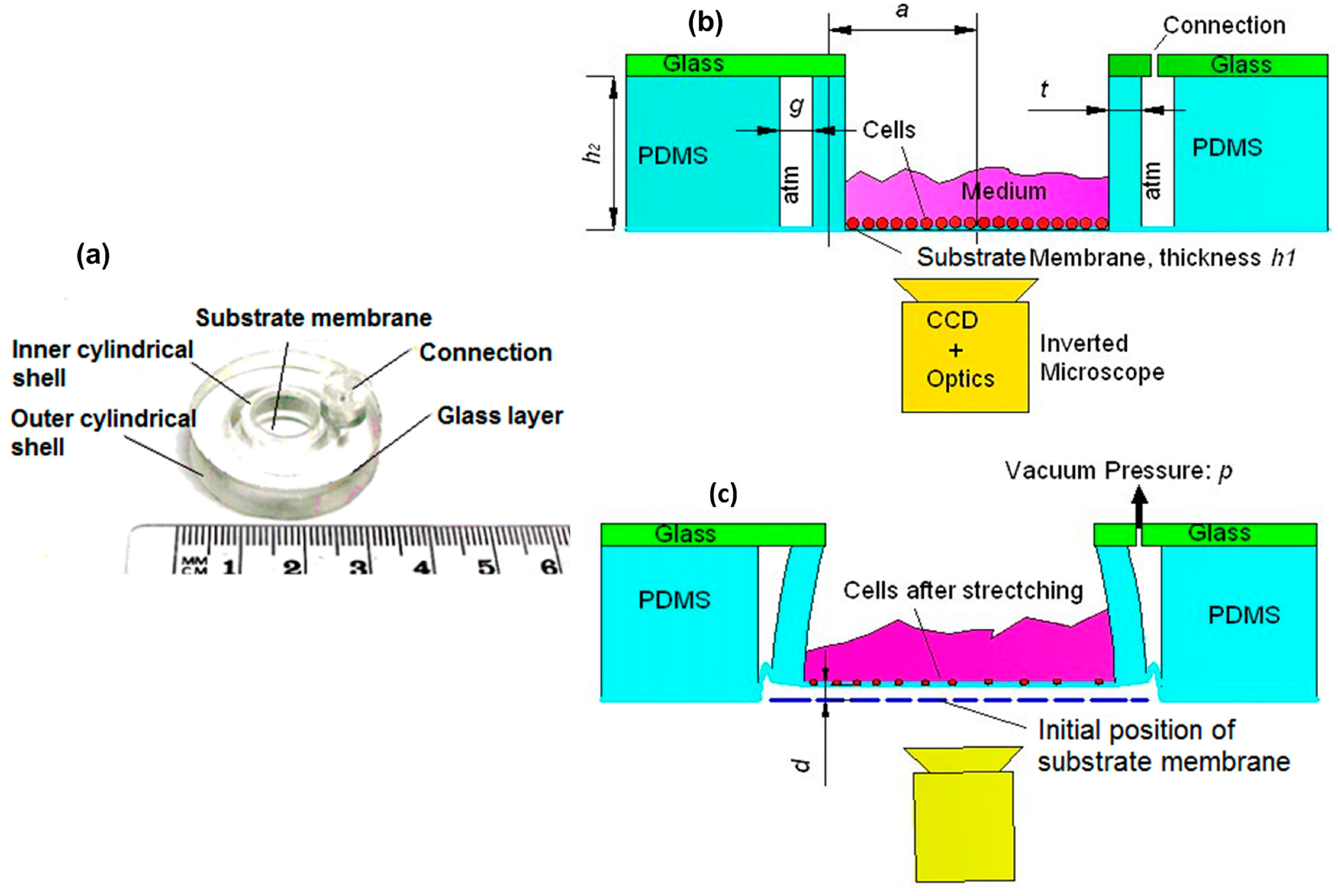
2.1. Experimental Characterisation of the Device

The concentric double-shell structure consisted of a PDMS substrate membrane, inner and outer PDMS cylindrical shells, and a rigid glass layer (see Figure 1a). The working principle of this structure was based on vacuum pressure, which deflected the inner shell as illustrated in Figure 1b,c. Consequently, the substrate membrane on which the cells were grown was stretched equiaxially. With the deformation of substrate membrane, the cells that adhered to the membrane were also stretched. The mechanical stimulation effect on stem cells was directly related to the in-plane strain of the substrate membrane [2]. The out-of-plane displacement (d in Figure 1c) determined the visibility in an inverted microscope to monitor the cells and influenced the adhesion of the cells on the substrate membrane.
Figure 1. (a) Photograph of a pneumatically actuated concentric double-shell structure for mechanical cell stimulation. Side view of the structure (b) before and (c) after deformation.
Micromachines 05 00868 g001
The in-plane strain and the out-of-plane displacement were measured in five locations on the membrane using computer vision similar to the method in [6]. In the measurements, 16 static partial vacuum pressures between 0 and 392 mbar were applied. After each pressure supply step, motorized optics (12× motorized zoom with 3-mm motorized fine focusing, Navitar, Inc., Rochester, NY, USA) were used for focusing on the membrane surface and a camera (Sony XCD-U100) for recording an image. The in-plane strain of the membrane was determined using three manually selected landmark points in each five locations. The (x,y) pixel coordinates of the centroids of the landmarks were recorded and the strain vectors between each pair of them were calculated for each pressure. The out-of-plane displacement was estimated from the displacement of the motorized focusing system.

2.2. Deformation Analysis of the Structure

The analytical model of the pneumatically actuated concentric double-shell structure was derived by separating the problem into the mechanics of a thin circular substrate membrane and the mechanics of a cylindrical shell. These two models were derived separately in Section 2.2.1 and Section 2.2.2, and incorporated to a model that described the entire structure. The geometric parameters of the structure that were used were those given in Table 1 and illustrated in Figure 1b.
Table 1. Geometric parameters of the concentric double-shell structure.
ParametersValues (mm)
Centreline radius of the inner cylindrical shell, a6.75
Thickness of the inner cylindrical shell wall, t1.5
Height of the cylindrical shells, h27
Thickness of the substrate membrane, h10.12
Width of the gap between the cylindrical shells, g2

2.2.1. Substrate Membrane

The substrate membrane was attached to one end of the inner cylindrical shells. Due to the radial outward bending of the inner shell wall, the circular membrane stretched uniformly outward. The loading type was illustrated in Figure 2b. To simplify the analytical model, in this study, PDMS was assumed as incompressible and linearly isotropic [18].
In the Cartesian coordinate system (Figure 2a), the strain energy Um of the circular membrane could be calculated as:
U m = E 2 ( 1 ν 2 ) V ( ε x x 2 + ε y y 2 + 1 ν 2 γ x y 2 + 2 ν ε x x ε y y ) d x d y d z
where, E was the Young’s Modulus of PDMS; ν was the Poisson’s ratio of PDMS, ν = 0.5 for incompressible material; εxx and εyy were the normal strain in x and y directions, respectively; γxy was the engineering shear strain.
After calculation, as presented in Appendix A, the strain energy of circular membrane could be obtained as below:
U m = π ( 5 + 3 ν ) E h 1 D 2 4 ( 1 ν 2 )
where h1 was the thickness of the membrane as shown in Figure 1b, D was the in-plane displacement of the circular membrane at the position r = a − t/2 with the parameter a and t shown in Figure 1b.
Figure 2. (a) The substrate membrane in Cartesian (x,y,z) and cylindrical (r,θ,z) coordinates. (b) Top view of the substrate membrane and its loading condition. (c) The inner cylindrical shell in a cylindrical coordinate system with the wall thickness of t and centerline radius of a. (d) Side layout view of half of the axial-symmetric structure after deflection, the dashed line represents the structure before deflection, where F1 and F2 were the stretching forces, g was the gap between two cylindrical shells, h2 was the height of the shell, α was the angle of the shell wall bended over, and d was the out-of-plane displacement.
Micromachines 05 00868 g002

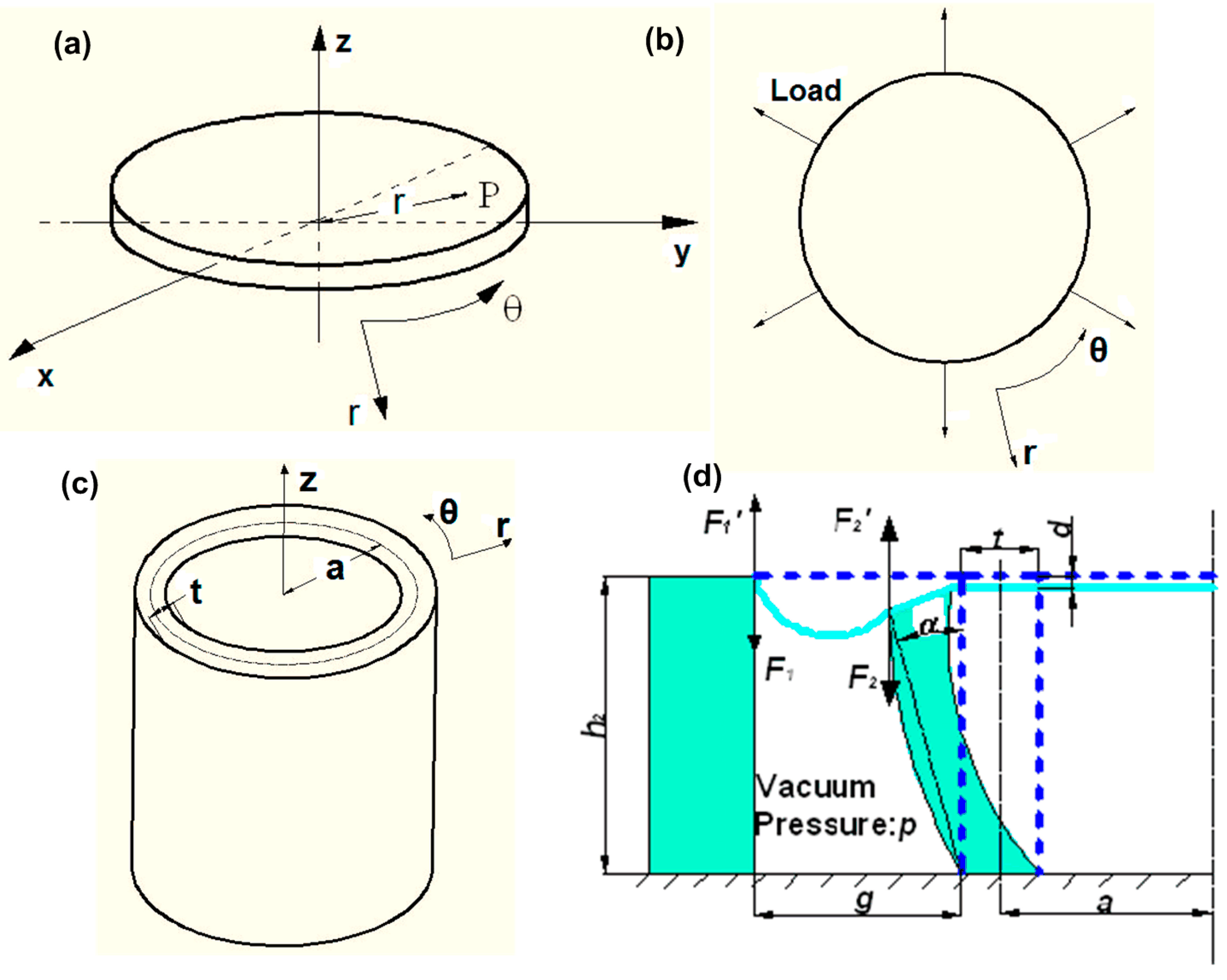
2.2.2. Cylindrical Shell

The inner cylindrical shell was subject to equally lateral stretching on the wall due to the vacuum pressure and the uniaxial compression caused by the membrane, as shown in Figure 2c. In the cylindrical coordinate system (Figure 2c), the strain energy Us of the inner cylindrical shell could be computed by integration over the volume of the shell. As the ratio between the radius a and the thickness t of the inner cylindrical shell was 4.5, the cylindrical shell could be considered as a thin-walled cylindrical shell [21]. Therefore, the term rdθ was introduced in Equation (3).
U s = E 2 ( 1 ν 2 ) V ( ε z 2 + ε θ 2 + 1 ν 2 γ z θ 2 + 2 ν ε z ε θ ) r d θ d r d z
where, εz was the normal strain in z direction; εθ was the normal strain in θ direction; γzθ was the engineering shear strain.
After calculation as presented in Appendix B, the strain energy of cylindrical shell could be obtained as below:
U s = π E 1 ν 2 { a t 3 3 h 2 3 D 2 + ( 1 ν 2 ) ( t a + t 3 12 a 3 ) h 2 D 2 5 + t 2 p g ( 2 a + t + g ) 12 E h 2 a + h 2 p 2 g 2 ( 2 a + t + g ) 2 16 E 2 a t }

2.2.3. In-Plane Strain and Out-of-Plane Displacement of Substrate Membrane

Incorporating models of the circular membrane and the inner cylindrical shell used a potential energy method. Applying Rayleigh-Ritz method, the boundary value D could be solved by minimizing the total potential energy of the entire structure [22]. The structure was assumed to deflect to a stable configuration that minimizes the total potential energy.
The total potential energy of the entire structure was:
Π = U m + U s + Ω
where, Um was the strain energy of the substrate membrane; Us was the strain energy of the inner cylindrical shell; Ω was the work potential.
After the calculation in Appendix C, the work potential was obtained as Equation (6):
Ω = Ω 1 + Ω 2 = 2 π p ( a + t 2 ) h 2 D 3 π g ( 2 a + t + g ) p D 2 4 h 2
Substituting Equations (2), (4) and (6) into Equation (5), we could obtain the expression of the total potential energy П.
In the minimum total potential energy principle, an infinitesimal variation from the stable state did not change the energy, which could be described by:
δΠ = δ ( U m + U s + Ω ) = 0
To solve the in-plane displacement D, we considered δП = 0 with respect to any infinitesimal variation of D, and had:
∂Π D = 0
Finally, we could get the expression of the in-plane displacement as:
D = 2 π p ( a + t 2 ) h 2 3 π t 2 p g ( 2 a + t + g ) 12 ( 1 ν 2 ) h 2 a π E 1 ν 2 [ ( 5 + 3 ν ) h 1 2 + 2 a t 3 3 h 2 3 + 2 ( 1 ν 2 ) ( t a + t 3 12 a 3 ) h 2 5 ] π p g ( 2 a + t + g ) 2 h 2
As stated in Section 2.1, the in-plane strain and the out-of-plane displacement of the substrate membrane played significant roles in the application of this mechanical cell stimulation device.
The in-plane strain ε of substrate membrane could be calculated as:
ε = w 2 r = D a t / 2 = 2 π p ( a + t 2 ) h 2 3 ( a t 2 ) π t 2 p g ( 2 a + t + g ) 12 ( 1 ν 2 ) h 2 a ( a t 2 ) π E 1 ν 2 [ ( 5 + 3 ν ) h 1 2 + 2 a t 3 3 h 2 3 + 2 ( 1 ν 2 ) ( t a + t 3 12 a 3 ) h 2 5 ] π p g ( 2 a + t + g ) 2 h 2
where, w2 was the displacement of circular membrane in the radial direction (see Appendix A).
When the structure was placed in the working position as shown in Figure 1b,c, the out-of-plane displacement d of the substrate membrane at z = h2 was calculated as Equation (11), which was based on the calculation in Equation (B6) (see Appendix B).
d = p g ( 2 a + t + g ) h 2 4 E a t + ν h 2 D a t 2 t D h 2 = p g ( 2 a + t + g ) h 2 4 E a t + [ 2 π ( a + t 2 ) h 2 3 π 2 p g ( 2 a + t + g ) 12 ( 1 ν 2 ) h 2 a ] ( ν h 2 a t 2 t h 2 ) π E 1 ν 2 [ ( 5 + 3 ν ) h 1 2 + 2 a t 3 3 h 2 3 + 2 ( 1 ν 2 ) ( t a + t 3 12 a 3 ) h 2 5 ] π p g ( 2 a + t + g ) 2 h 2
For the specific structure with parameters as given in Table 1, the in-plane strain and the out-of-plane displacement were:
ε = 1.8232 p 378550 E 0.76 p × 100 %
d = 40.835 p 3785.5 E 0.0076 p + 59 p 10000 E
where, p, E, ε, d had the units of (Pa), (MPa), (%) and (μm), respectively.

2.3. Determination of the Elastic Modulus of PDMS

The elastic modulus of PDMS depended on the fabrication conditions [23,24,25,26,27]. In this study, PDMS was prepared by mixing a silicone elastomer prepolymer (base) and a cross-linker (curing agent) with a weight ratio of 10:1. Curing was processed in an oven (Binder GmbH, Tuttlingen, Germany) at 65 °C for two hours. According to Fuard et al. [27], the elastic modulus of PDMS could vary from 0.8 MPa to 4 MPa based on the curing time and temperature. Therefore, the elastic modulus of the PDMS in this study should be determined for the analytical model.
In this study, we used a computational approach for estimating the elastic modulus of the PDMS in this device. A computational model of the device was developed in COMSOL 3.5 (COMSOL Inc., Burlington, MA, USA) by FE approach, and was used together with experimental data for determining the elastic modulus for the analytical model.

2.3.1. Constitutive Model

Using the geometric parameters in Figure 1 and Table 1, a 3D model was created in COMSOL 3.5 as shown in Figure 3a,b.
As mentioned by Yoon et al. [18], PDMS was nearly incompressible after curing. In addition, when the material underwent a strain larger than 1%–2%, nonlinear elastic theory was more accurate to describe its mechanical behavior, wherein hyperelastic models were commonly applied [28]. In this study, Neo-Hookean model was determined as the constitutive model of PDMS. The strain energy density of incompressible Neo-Hookean material, W could be expressed as:
W = C 1 ( I 1 3 )
where, I1 was the first invariant of the left Cauchy-Green deformation tensor,
I 1 = λ 1 2 + λ 2 2 + λ 3 2
in which, λ1, λ2, λ3 were the principal stretch ratios in three directions. In the cylindrical coordinate system:
λ 1 = 1 + ε r
λ 2 = 1 + ε θ
λ 3 = 1 + ε z
where, εr, εθ and εz were strain components in cylindrical coordinates.
In Equation (14), the material constant C1 = G/2 was for incompressible material, where G was the shear modulus. Because PDMS was incompressible, the Poisson’s ratio ν was 0.5 for incompressible. However, in this study, ν was set as 0.49 for preventing a numerical error in computation.

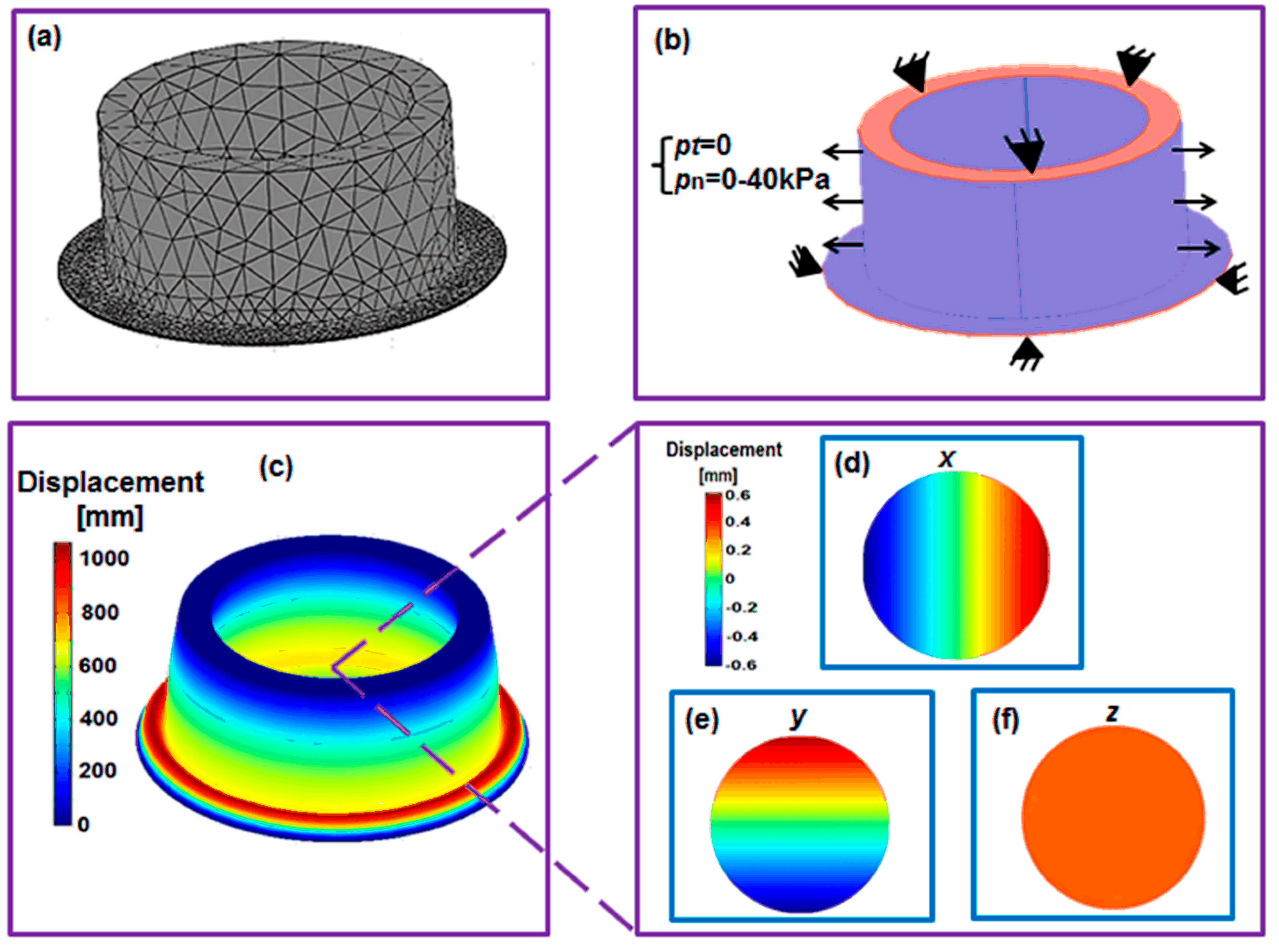
2.3.2. Boundary Conditions and Mesh

To mimic the effect of the vacuum pressure, we applied lateral normally outward pressure on the shell wall (blue areas in Figure 3b), varying from 0 to 40kPa. As depicted in Figure 1, one end of the shell was attached to a glass layer, and the edge of the membrane was attached to the end of the outer cylindrical shell. Neither of them had displacement, thus we could fix one end of the shell and the edge of the membrane (red areas in Figure 3b).
The mesh consisted of 22,339 triangular elements (Figure 3a) with Lagrange quadratic basis function in the whole structure was sufficient for the convergence purpose for the whole structure.
Figure 3. (a) The mesh and (b) boundary conditions of the computational model. (c) The deflected structure under the loading of 40,000 Pa. (d) The x-direction, (e) y-direction and (f) z-direction (out-of-plane) displacements in the substrate membrane.
Micromachines 05 00868 g003

2.3.3. Estimation of the Elastic Modulus

As mentioned previously, the elastic modulus E sit within the range of [0.8, 4] MPa. Thus, a parametric variation study of Young’s modulus was hereby carried out. In the Matlab script of the computational model, Young’s modulus E was determined as a range of [0.8, 4] MPa, and the model was revolved by COMSOL pre-processor. Moreover, to calculate the in-plane strain, we needed to convert the displacements given in the Cartesian coordinates (e.g., in Figure 3d,e) into the cylindrical coordinates as presented in Equation (17):
ε = d x 2 + d y 2 r × 100 %
where, ε was the in-plane strain; dx was the in-plane displacement in x direction at the point (x,y); dy was the in-plane displacement in y direction at the point (x,y); r was the radial position, r = x 2 + y 2 .
Finally, after fitting all of the computational results to the experimental data, we found the computational results at E = 2 MPa fitted the experimental data well with the root-mean-square error (RMSE) of 0.2% and 16.4 μm on the in-plane strain and out-of-plane displacement, respectively (see Figure 4a,b).

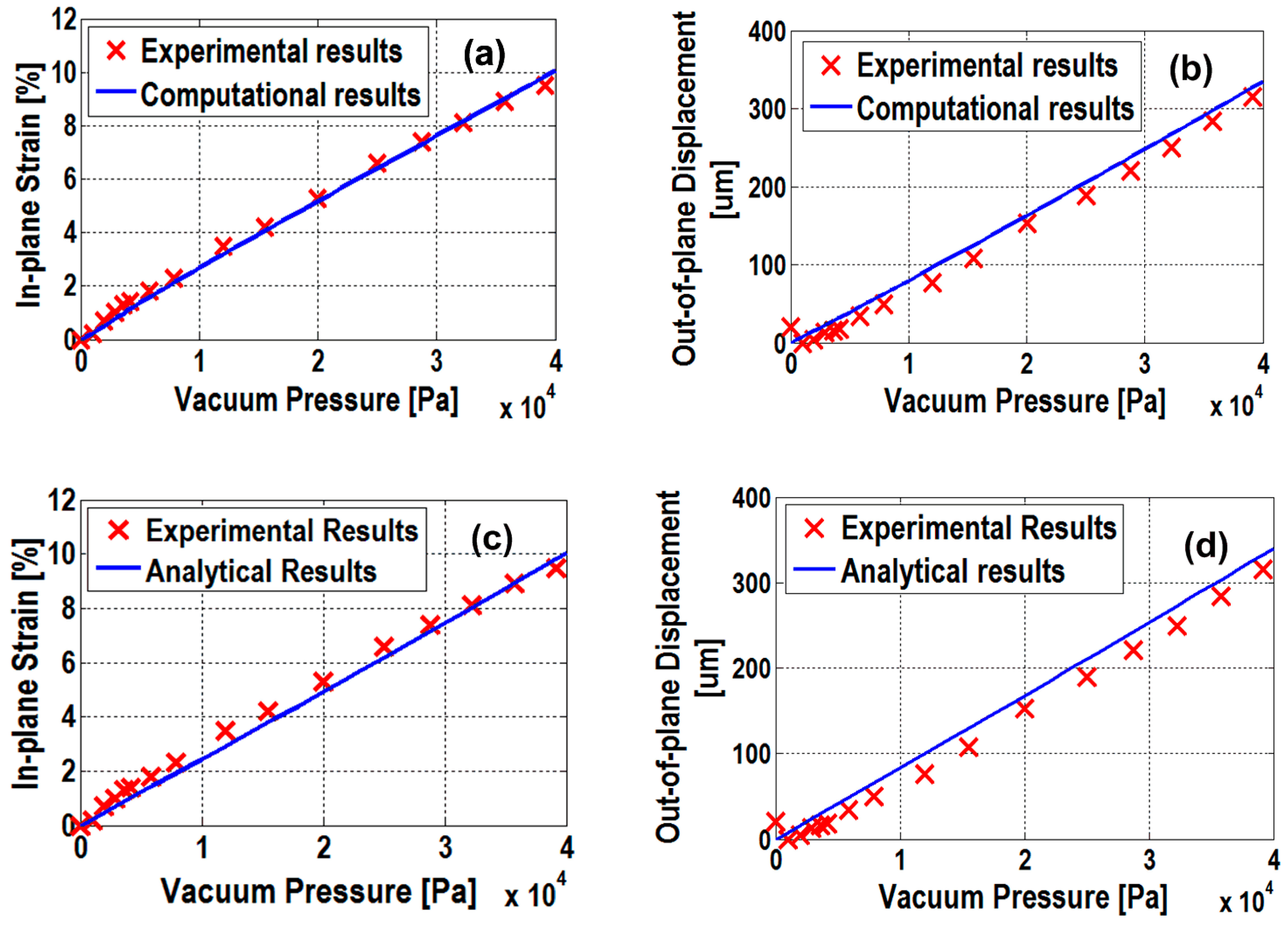
3. Analytical Model Validation

Applying E = 2 MPa to the analytical model (Equations (12) and (13)), the results were shown in Figure 4c,d. A RMSE of in-plane strain and out-of-plane displacement was calculated as 0.33% and 18 μm, respectively. The larger RMSE of analytical model than the computational model was mainly due to the assumption of linear mechanical behavior of PDMS in creating the analytical model.
Furthermore, to validate the analytical model with an increase in load, we calculated the relative errors as shown in Figure 5. It was found that large relative errors occur at lower loading (small deformation). This was because the substrate membrane attached to the cylindrical shell was initially loose, and then tightened by increasing the load. Nevertheless, with the increase in loading, the linearity improved and the analytical model predicted the deformation more accurately. In a typical use of the analytical model, the capabilities of a certain structure to maximize the in-plane strain and minimize the out-of-plane displacement with large pressure values were of interest. Therefore, the analytical model predicted, with sufficient accuracy, the deformation behavior of these types of structures in the load range within practical interest. Moreover, it was observed that larger error appears in the out-of-plane displacement than that in the in-plane strain. One possible reason was the use of unaided-eye detection in the measurement of out-of-plane displacement, rather than an automatic system.
Figure 4. Computational vs. experimental results on (a) in-plane strain and (b) out-of-plane displacement. Analytical vs. experimental results on (c) in-plane strain and (d) out-of-plane displacement.
Micromachines 05 00868 g004
Figure 5. The relative errors between experimental results and analytical results.
Micromachines 05 00868 g005

4. Discussion

In this paper, an analytical model was developed to predict the mechanical behavior of the cell stretching device that had been developed by Kreutzer et al. [6], according to which, the applied loading could be quantitatively determined, or the structure might be modified to achieve a needed strain in different cell specific applications. Additionally, we also developed a computational model in this study not only to show the mechanical behavior of the device, but also to determine the mechanical property of the material for fabricating this device (PDMS).
One of the main limitations in this study was the neglect of influence of medium. However, fluid shear stress also serves as mechanical stimulation to the stem cells, which can enhance the differentiation and proliferation of stem cells [29,30,31]. In addition, the assumption of slender longitudinal-section of shell in the analytical model may limit the applicable range of the analytical model. To predict the deformation of slender shell, Euler-Bernoulli beam theory was used, in which the shear deformation and rotational inertia in the deformation analysis of the shell were not considered. So, for the future structural modification purposes, if the stout longitudinal-section of shell structure is involved, this analytical model will be less accurate to predict the mechanical behavior of the structure. In this case, Timoshenko beam theory should be applied for analysis of the stout shell, nevertheless, it will bring cumbersome computation to resolve the model. Finally, in our study, to simplify the analytical model, PDMS was assumed as linearly isotropic. However, if the device is more deformed, the assumption of linearly isotropic mechanical behavior of PDMS will limit the predicted accuracy. Thus, hyperelastic constitutive model should be applied to describe the mechanical properties of PDMS, and solved by numerical approach.
As mentioned in Section 1, different cell types may response to different levels of strain. In addition to the application in cardiac cell mechanobiology, it is also suggested to use this device in the other mechanosensitive cells culture. For example, a mechanical strain of 5% is considered as threshold for enhancing the osteogenic differentiation [15,16]. Thus, to mechanically stimulate the bone cells, a preferable loading of 20 kPa is suggested to be applied in our device, which will result in an out-of-plane displacement of 170 μm. Das et al. showed a strain of 3% could stimulate the chondrocytes to a biochemical response [32]. Corresponding to our prediction, a loading of 13 kPa needs to be applied to this device so as to achieve a strain magnitude of 3%. Therefore, the proposed model can be used for estimating the loads needed to achieve a certain strain. Furthermore, Wang et al. carried out the NIH/3T3 (National Institute of Health/3-day transfer, inoculum 3 × 10⁵ cells) fibroblasts stimulation by applying high-level equiaxial strains (12%–27%) to the cells [8]. Moreover, they employed an inverted microscope (Leica DM16000, Leica Microsystems, Wetzlar, Germany) to view the cells, and performed the scanning to obtain clear cell images [8]. In the device developed by Kreutzer et al. [6], according to our prediction, to achieve such high-level strain, a loading up to 100 kPa is needed, which will result in an out-of-plane displacement as high as 895 μm. Such large displacement has been beyond the detection capability of CCD camera. One solution we suggest is to modify the structure of this device, so as to guarantee the out-of-plane displacement is within the capability of CCD camera. Therefore, our analytical model gives a theoretical basis for modifying the structure. More importantly, for most of the cell stretching devices, the cell stimulation is achieved by stretching the substrate membrane under pneumatic pressure [7,8,17]. Thus, to some extent, the mechanical analysis of the substrate membrane in this study will also be beneficial for modeling those devices. For instance, the strain energy of the substrate membrane (Equation (2)) is applicable to most cell stretching device, according to which the deformation-loading relationship can also be obtained using minimal potential energy principle.
Furthermore, in this study, using the computational model to determine the mechanical property of the material that is used for fabricating the device has been proved practical and accurate. This method is also considered suitable to determine the materials properties of other devices and actuators, especially suitable for a device or actuator with complex structure.

5. Conclusions

This paper has presented both analytical and computational models of pneumatically actuated concentric double-shell structures that can be used for mechanical stimulation of mechanosensitive cells. The analytical model based on the linearly isotropic constitutive model presents the in-plane strain and the out-of-plane displacement as a function of applied pressure, which allows people to quantitatively determine the applied load, according to their specific needs in different cell culture studies. Moreover, it provides insights to understand the behavior of the structure and, in so doing, gives a theoretical basis for modifying the structure in some applications. The computational model in this study not only shows the mechanical behavior of the device (i.e., the displacement distribution, etc.), but also determines the Young’s modulus of the material of the device (PDMS). More importantly, not limited to the device in this study, this method is also considered applicable to determine the materials properties of many other devices and actuators with complex structures.

Acknowledgments

The authors would like to acknowledge the funding from Academy of Finland and the Finnish Funding Agency for Technology and Innovation (TEKES) under the grant of STEMFUNC (grant number 123762) and Human Spare Parts projects, respectively.

Author Contributions

Feihu Zhao made the substantial contribution to the model development, data analysis and paper writing. Joose Kreutzer provided the experimental data, and assisted the revision. Sami Pajunen helped check the algorithm of the analytical model, and gave final approval of the version to be submitted. Pasi Kallio helped revise the paper, and gave final approval of version to be submitted.

Appendix A: Deformation Analysis of Circular Membrane

To obtain the strain energy function of the circular membrane in our study, the variables of εxx , εyy and γxy in Equation (1) were calculated as follows. Firstly, these strains were converted from Cartesian coordinate to cylindrical coordinates as below:
ε x x = d u d x = ( d w 2 ) cos θ ( d r ) cos θ = d w 2 d r
ε y y = d v d y = ( d w 2 ) sin θ ( d r ) sin θ = d w 2 d r
γ x y = d u d y + d v d x = d w 2 d r cot θ + d w 2 d r tan θ
where, εxx and εyy were the normal strain in x and y directions, respectively; γxy was the engineering shear strain, u was the displacement in x direction, v was the displacement in y direction, and w2 was the displacement in the radial direction.
Substituted Equation (A1a–c) into Equation (1) to obtain the strain energy for the circular substrate membrane in cylindrical coordinates as:
U m = E 2 ( 1 ν 2 ) V [ ( d w 2 d r ) 2 + ( d w 2 d r ) 2 + 2 ν ( d w 2 d r ) ( d w 2 d r ) + 1 ν 2 ( d w 2 d r cot θ + d w 2 d r tan θ ) 2 ] r d r d θ d z
Considering the boundary conditions:
w 2 | r = 0 = 0  and  w 2 | r = a t / 2 = D ,
and the fact that the strain should be equally distributed in the membrane, a function for w2 was obtained as:
w 2 = D r a t 2
where, a was the centerline radius of the inner cylindrical shell as shown in Figure 1b; t was the wall thickness of the inner cylindrical shell; D was the in-plane displacement of the circular membrane at the position r = a − t/2.
Substituting Equation (A3) into Equation (A2) and integrated over the volume in the cylindrical coordinate system, the strain energy expression of the circular substrate membrane under equally outward stretching could be expressed as Equation (2).

Appendix B: Deformation Analysis of Cylindrical Shell

To calculate the normal strain in θ direction (εθ) of cylindrical shell, since the loading did not involve torsion in the θ direction of the shell, the strain in θ direction could be expressed as:
ε θ = w 1 r
where w1 was the deflection of the shell wall.
In the longitudinal direction (z-direction), there was uniaxial compression due to the stretching of the substrate membrane, as shown in Figure 2d. Therefore, the force exerted on the end of the cylindrical shell was:
F 2 = F 2 = p A 1 2
where, p was the vacuum pressure; A1 was the cross-sectional area of the space, where the vacuum pressure was applied; A1 = π[(a + g + t/2)2 (a + t/2)2]; and g was the gap width, as shown in Figure 2d.
The strain due to F2 was:
ε z 1 = F 2 E A 2
where A2 was the cross sectional area of the cylindrical shell, A2 = π[(a + t/2)2 − (a − t/2)2].
Therefore,
ε z 1 = p A 1 2 E A 2 = p g ( 2 a + t + g ) 4 E a t
The strain due to Poisson’s effect could be expressed as:
ε z 2 = ν ε θ = ν w 1 r
One end of the cylindrical shells was fixed to a rigid glass plate and the other was attached to the substrate membrane. Thus, under vacuum pressure, the shell wall would not expand equally at different heights. Here, the longitudinal-section of the shell wall was considered to be a beam shape and deflected as shown in Figure 2d. The slenderness value (a ratio between the height h2 and the thickness t) of the longitudinal section of the bending shell wall was approximately 5. According to Kikidis et al. [33], the Euler-Bernoulli beam theory could be used to analyze the out-of-plane strain due to bending, which was:
ε z 3 = ( a r ) w 1 , z z
where w1,z represented the first derivative of w1 with respect to z, and w1,zz was the second derivative of w1.
By combining Equations (B3)–(B5), the total out-of-plane strain was obtained as:
ε z = p g ( 2 a + t + g ) 4 E a t ν w 1 r + ( a r ) w 1 , z z
As no torsion was exerted on the shell, the shear strain γzθ = 0.
Considering the boundary conditions (one end of the cylindrical shell was fixed and the other end was attached to the substrate membrane), we obtained:
w 1 | z = 0 = 0 w 1 , z | z = 0 = 0 w 1 | z = h 2 = D
To satisfy the boundary conditions, the shape function of the wall of the inner cylindrical shell after deformation was assumed to be:
w 1 = D ( z h 2 ) 2
Thus,
w 1 , z = 2 D z h 2 2
w 1 , z z = 2 D h 2 2
By substituting Equation (B7a–c) to the expressions of the strain components εz, εθ, γzθ, and then substituting them into Equation (3), the strain energy of the shell was
U s = E 2 ( 1 ν 2 ) V { 4 D 2 h 2 4 r 3 [ 2 a w 1 , z z 2 D p g ( 2 a + t + g ) E h 2 a t ] r 2 + [ 4 D 2 a 2 h 2 4 + [ p g ( 2 a + t + g ) 4 E a t ] 2 a D p g ( 2 a + t + g ) 2 E h 2 2 a t ] r + ( 1 ν 2 ) D 2 z 4 h 2 4 1 r } d θ d r d z
Logarithmic terms occurring in the integration were approximated by a series of ascending powers:
ln ( 1 + t 2 a 1 t 2 a ) = 2 n = 0 ( t 2 a ) 2 n + 1 2 n + 1
Neglecting the terms with a power higher than two led to Equation (B10):
ln ( 1 + t 2 a 1 t 2 a ) t a + t 3 12 a 3
By integrating Equation (B8) over the volume of the inner cylindrical shell, we obtained the expression of strain energy of cylindrical shell as Equation (4).

Appendix C: Calculation of Total Potential Energy

The total work potential was caused by (i) the vacuum pressure exerted on the shell wall (Ω1) and (ii) the stretching force (Ω2) as shown in Figure 2d. The work potential generated by the vacuum pressure could be calculated as:
Ω 1 = 0 h 2 [ 2 π p ( a + t 2 ) w 1 ] d z
Substituting Equation (B7a) into Equation (C1) and integrating it led to
Ω 1 = 2 π p ( a + t 2 ) h 2 D 3
The work potential due to the uniaxial stretching force F2 caused by the membrane (see Figure 2d) was approximately:
Ω 2 = 0 α M d α
where, M was the moment due to F2, which could be calculated as:
M = F 2 D = π g ( 2 a + t + g ) p D 2
The angle α could be considered approximately as the angle that the wall of the inner cylindrical shell bended over, which satisfied tanα = D/h2, as shown in Figure 2d. In this study, the angle α was very small, and α ≈ D/h2.
Then,
d α = d D h 2
After substituting Equations (C4) and (C5) into Equation (C3) and integrating, we obtained:
Ω 2 = π g ( 2 a + t + g ) p D 2 4 h 2
Thus, the total work potential Ω could be obtained by combining Ω1 and Ω2 together as shown in Equation (6).

Conflicts of Interest

The authors declare no conflict of interest.

References

  1. Boerboom, R.A.; Rubbens, M.P.; Driessen, N.J.B.; Bouten, C.V.C.; Baaijens, F.P.T. Effect of strain magnitude on the tissue properties of engineered cardiovascular constructs. Ann. Biomed. Eng. 2008, 36, 244–253. [Google Scholar] [CrossRef] [PubMed]
  2. Desmaele, D.; Boukallel, M.; Regnier, S. Actuation means for the mechanical stimulation of living cells via microelectromechanical systems: A critical review. J. Biomech. 2011, 44, 1433–1446. [Google Scholar] [CrossRef] [PubMed] [Green Version]
  3. Gwak, S.J.; Bhang, S.H.; Kim, I.K.; Kim, S.S.; Cho, S.W.; Jeon, O.; Yoo, K.J.; Putnam, A.J.; Kim, B.S. The effect of cyclic strain on embryonic stem cell-derived cardiomyocytes. Biomaterials 2008, 29, 844–856. [Google Scholar] [CrossRef] [PubMed]
  4. Huang, Y.; Zheng, L.S.; Gong, X.H.; Jia, X.L.; Song, W.; Liu, M.L.; Fan, Y.B. Effect of Cyclic Strain on Cardiomyogenic Differentiation of Rat Bone Marrow Derived Mesenchymal Stem Cells. PloS One 2012, 7, e34960. [Google Scholar] [CrossRef] [PubMed]
  5. Yu, T.; Miyagawa, S.; Miki, K.; Saito, A.; Fukushima, S.; Higuchi, T.; Kawamura, M.; Kawamura, T.; Ito, E.; Kawaguchi, N.; Sawa, Y.; Matsuura, N. In vivo differentiation of induced pluripotent stem cell-derived cardiomyocytes. Circ. J. Off. J. Jpn. Circ. Soc. 2013, 77, 1297–1306. [Google Scholar]
  6. Kreutzer, J.; Ikonen, L.; Hirvonen, J.; Pekkanen-Mattila, M.; Aalto-Setala, K.; Kallio, P. Pneumatic cell stretching system for cardiac differentiation and culture. Med. Eng. Phys. 2014, 36, 496–501. [Google Scholar] [CrossRef] [PubMed]
  7. Simmons, C.S.; Petzold, B.C.; Pruitt, B.L. Microsystems for biomimetic stimulation of cardiac cells. Lab Chip 2012, 12, 3235–3248. [Google Scholar] [CrossRef] [PubMed]
  8. Wang, D.; Xie, Y.Y.; Yuan, B.; Xu, J.; Gong, P.Y.; Jiang, X.Y. A stretching device for imaging real-time molecular dynamics of live cells adhering to elastic membranes on inverted microscopes during the entire process of the stretch. Integr. Biol. 2010, 2, 288–293. [Google Scholar] [CrossRef]
  9. Brown, T.D. Techniques for mechanical stimulation of cells in vitro: A review. J. Biomech. 2000, 33, 3–14. [Google Scholar] [CrossRef] [PubMed]
  10. Kim, D.H.; Wong, P.K.; Park, J.; Levchenko, A.; Sun, Y. Microengineered platforms for cell mechanobiology. Ann. Rev. Biomed. Eng. 2009, 11, 203–233. [Google Scholar] [CrossRef]
  11. Bottlang, M.; Simnacher, M.; Schmitt, H.; Brand, R.A.; Claes, L. A cell strain system for small homogeneous strain applications. Biomed. Tech. 1997, 42, 305–309. [Google Scholar] [CrossRef]
  12. Colombo, A.; Cahill, P.A.; Lally, C. An analysis of the strain field in biaxial Flexcell membranes for different waveforms and frequencies. Proc. Inst. Mech. Eng. Part H J. Eng. Med. 2008, 222, 1235–1245. [Google Scholar] [CrossRef]
  13. Winston, F.K.; Macarak, E.J.; Gorfien, S.F.; Thibault, L.E. A system to reproduce and quantify the biomechanical environment of the cell. J. Appl. Physiol. 1989, 67, 397–405. [Google Scholar] [PubMed]
  14. Gopalan, S.M.; Flaim, C.; Bhatia, S.N.; Hoshijima, M.; Knoell, R.; Chien, K.R.; Omens, J.H.; McCulloch, A.D. Anisotropic stretch-induced hypertrophy in neonatal ventricular myocytes micropatterned on deformable elastomers. Biotechnol. Bioeng. 2003, 81, 578–587. [Google Scholar] [CrossRef] [PubMed]
  15. Huang, Y.; Niu, X.F.; Song, W.; Guan, C.D.; Feng, Q.L.; Fan, Y.B. Combined effects of mechanical strain and hydroxyapatite/collagen composite on osteogenic differentiation of rat bone marrow derived mesenchymal stem cells. J. Nanomater. 2013, 2013. [Google Scholar] [CrossRef]
  16. Jacobs, C.; Grimm, S.; Ziebart, T.; Walter, C.; Wehrbein, H. Osteogenic differentiation of periodontal fibroblasts is dependent on the strength of mechanical strain. Arch. Oral. Biol. 2013, 58, 896–904. [Google Scholar] [CrossRef] [PubMed]
  17. Thompson, M.S.; Abercrombie, S.R.; Ott, C.E.; Bieler, F.H.; Duda, G.N.; Ventikos, Y. Quantification and significance of fluid shear stress field in biaxial cell stretching device. Biomech. Model. Mechanobiol. 2011, 10, 559–564. [Google Scholar] [CrossRef] [PubMed]
  18. Yoon, S.H.; Reyes-Ortiz, V.; Kim, K.H.; Seo, Y.H.; Mofrad, M.R.K. Analysis of circular PDMS microballoons with ultralarge deflection for MEMS design. J. Microelectromech. Syst. 2010, 19, 854–864. [Google Scholar] [CrossRef]
  19. Zhao, Y.H.; Zhou, J.H.; Dai, W.; Zheng, Y.Z.; Wu, H.K. A convenient platform of tunable microlens arrays for the study of cellular responses to mechanical strains. J. Micromech. Microeng. 2011, 21, 054017. [Google Scholar] [CrossRef]
  20. Vaughan, T.J.; Haugh, M.G.; McNamara, L.M. A fluid-structure interaction model to characterize bone cell stimulation in parallel-plate flow chamber systems. J. R. Soc. Interface 2013, 10, 20120900. [Google Scholar]
  21. Ventsel, E.; Krauthammer, T. Thin Plates and Shells: Theory, Analysis, and Applications; CRC Press: New York, NY, USA, 2001. [Google Scholar]
  22. Dow, J.A. A Unified Approach to the Finite Element Method and Error Analysis Procedures; Academic Press: Waltham, MA, USA, 1998. [Google Scholar]
  23. Carrillo, F.; Gupta, S.; Balooch, M.; Marshall, S.J.; Marshall, G.W.; Pruitt, L.; Puttlitz, C.M. Nanoindentation of polydimethylsiloxane elastomers: Effect of crosslinking, work of adhesion, and fluid environment on elastic modulus. J. Mater. Res. 2005, 20, 2820–2830. [Google Scholar] [CrossRef]
  24. Liu, M.; Chen, Q.F. Characterization study of bonded and unbonded polydimethylsiloxane aimed for bio-micro-electromechanical systems-related applications. J. Micro/Nanolithogr. MEMS MOEMS 2007, 6, 023008. [Google Scholar] [CrossRef]
  25. Wu, C.L.; Lin, H.C.; Hsu, J.S.; Yip, M.C.; Fang, W.L. Static and dynamic mechanical properties of polydimethylsiloxane/carbon nanotube nanocomposites. Thin Solid Films 2009, 517, 4895–4901. [Google Scholar] [CrossRef]
  26. Cotton, D.P.J.; Popel, A.; Graz, I.M.; Lacour, S.P. Photopatterning the mechanical properties of polydimethylsiloxane films. J. Appl. Phys. 2011, 109, 054905. [Google Scholar] [CrossRef]
  27. Fuard, D.; Tzvetkova-Chevolleau, T.; Decossas, S.; Tracqui, P.; Schiavone, P. Optimization of poly-di-methyl-siloxane (PDMS) substrates for studying cellular adhesion and motility. Microelectron. Eng. 2008, 85, 1289–1293. [Google Scholar] [CrossRef]
  28. Misra, S.; Ramesh, K.T.; Okamura, A.M. Modelling of non-linear elastic tissues for surgical simulation. Comput. Method Biomech. Biomed. Eng. 2010, 13, 811–818. [Google Scholar] [CrossRef]
  29. Shafa, M.; Krawetz, R.; Zhang, Y.; Rattner, J.B.; Godollei, A.; Duff, H.J.; Rancourt, D.E. Impact of stirred suspension bioreactor culture on the differentiation of murine embryonic stem cells into cardiomyocytes. BMC Cell Biol. 2011, 12. [Google Scholar] [CrossRef]
  30. Geuss, L.R.; Suggs, L.J. Making cardiomyocytes: How mechanical stimulation can influence differentiation of pluripotent stem cells. Biotechnol. Prog. 2013, 29, 1089–1096. [Google Scholar] [CrossRef] [PubMed]
  31. Huang, Y.; Jia, X.L.; Bai, K.; Gong, X.H.; Fan, Y.B. Effect of fluid shear stress on cardiomyogenic differentiation of rat bone marrow mesenchymal stem cells. Arch. Med. Res. 2010, 41, 497–505. [Google Scholar] [CrossRef] [PubMed]
  32. Das, R.H.J.; Jahr, H.; Verhaar, J.A.N.; van der Linden, J.C.; van Osch, G.J.V.M.; Weinans, H. In vitro expansion affects the response of chondrocytes to mechanical stimulation. Osteoarthr. Cartil. 2008, 16, 385–391. [Google Scholar] [CrossRef] [PubMed]
  33. Kikidis, M.L.; Papadopoulos, C.A. Slenderness ratio effect on cracked beam. J. Sound. Vib. 1992, 155, 1–11. [Google Scholar] [CrossRef]

