1. Introduction
In recent years, rapid technological progress has been made in the integration of micro-electro-mechanical systems (MEMS) in the biomedical field, driven by the systems’ compact size, low power consumption, and energy-harvesting capabilities [
1,
2,
3]. Thanks to advances in biomedical and microelectronic technologies, it is now possible to implant microdevices inside the human body, as envisaged in, e.g., [
4,
5]. These devices can be wirelessly powered [
6], take local measurements or perform actions relevant to specific therapies or the tracking of biochemical dynamics, and communicate information or action feedback to the exterior.
Among MEMS, piezoelectric micromachined ultrasonic transducers (pMUTs) have emerged as a promising solution for next-generation implantable bio-sensing systems [
7,
8,
9]: by combining MEMS technology with a piezoelectric thin-film layer, micro-scaled devices that operate at MHz frequencies can be designed, making them fast and well suited to coupling with high-impedance fluids. In addition, the piezoelectric properties of the active layer enable the conversion of ultrasound energy into electrical energy and vice versa. For these reasons, pMUTs are widely used in several medical applications, including imaging [
10,
11], local therapy [
8,
12,
13], and energy harvesting [
14]. In the latter field, pMUTs are an excellent alternative to conventional batteries as they supply electrical energy to bio-sensing systems while reducing the occupied area drastically and eliminating the need for periodic surgical replacements [
8].
Specifically, this work investigates the energy-harvesting performance of pMUT-based devices for wireless power delivery to implantable medical devices, ensuring compliance with the strict performance and bio-compatibility requirements of the United States Food and Drug Administration (FDA) [
15]. Ultrasonic (US) waves are favored over electromagnetic waves due to their superior properties in biological environments, including significantly higher safe exposure limits, lower tissue attenuation (0.5–1 dB/cm·MHz), and shorter wavelengths (approximately 1.5 mm at 1 MHz). These advantages make US-based systems, and pMUT technology in particular, well suited to reliable and efficient power and data transfer in medical applications. The recent use of pMUTs in bio-medicine is also due to the development of biocompatible piezoelectric materials such as aluminum nitride (AlN), which can replace the more widely used and efficient, but lead-contaminated, lead zirconate titanate (PZT), which is typically chosen in microelectronic applications. Notably, the addition of scandium (Sc) to AlN has been found to enhance the effectiveness of piezoelectric energy conversion, providing an acceptable alternative to PZT in biological environments.
Expanding upon the analysis initiated in [
16], where only the smallest geometry was investigated, this work focuses on the numerical evaluation of three existing pMUT designs with different size [
17], analyzed in both transmitting and receiving configurations, to meet the following performance requirements.
Given the toxicity of lead and its incompatibility with biomedical and environmental safety standards, a lead-free alternative to PZT, the most widely used piezoelectric material, must be explored.
The device should occupy a footprint of approximately 100 × 100 m2 to ensure suitability for integration into next-generation biomedical implants.
The device must be capable of delivering a minimum power of at least 100 nW and generating an output voltage of at least 150 mV, at a distance of 5 mm in a ballistic gel medium.
It is worth mentioning that only objective 1 has been partially studied in the past, while objectives 2 and 3 have not been well explored in the literature.
The paper is therefore organized as follows.
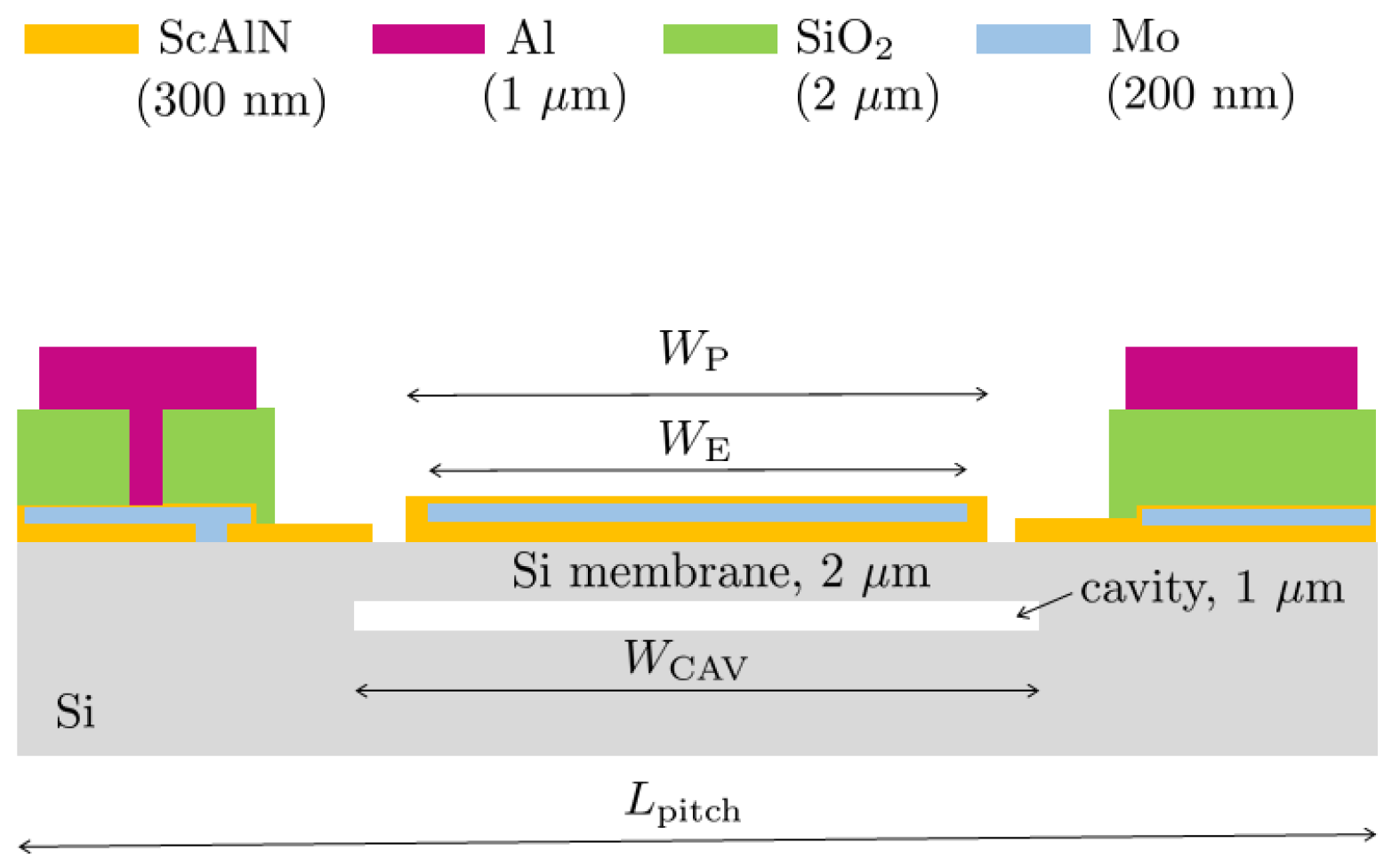
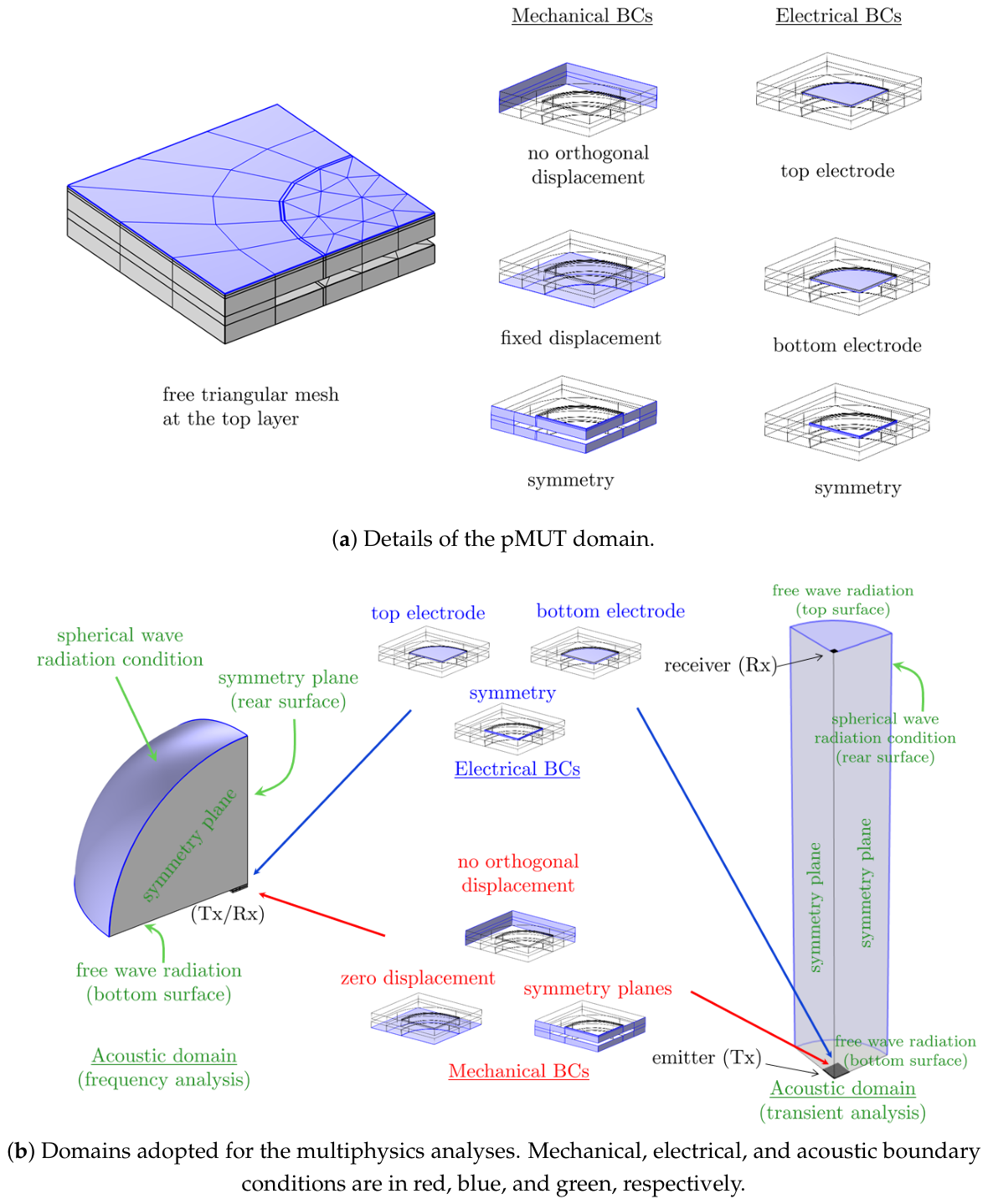
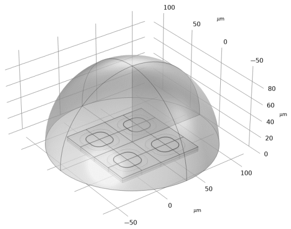
Section 2 describes the pMUT geometry and the hypotheses and methods of the three-dimensional numerical simulations, performed with finite elements (FE) via COMSOL Multiphysics
®, release 6.3.
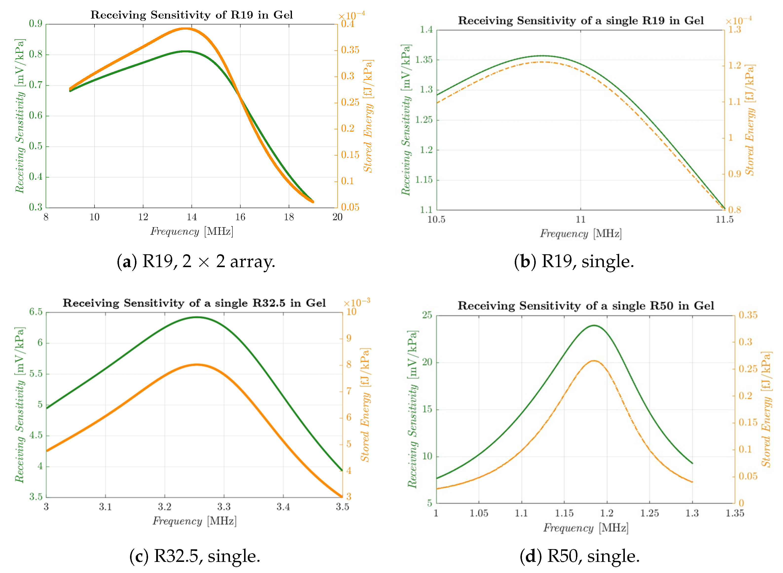
Section 3 summarizes the results of the analyses, carried out in the frequency and transient domain, for different configurations of transmitter (Tx) and receiver (Rx).
Section 4 reports the electrical performance of the devices when non-idealities are introduced (e.g., acoustic attenuation). A list of acronyms is provided after the conclusions, collected in
Section 5.
4. Discussion
This section discusses critical physical effects and engineering requirements that are not directly captured by the FE modeling. Specifically, the discussion covers safety limits for acoustic radiation in the human body, signal attenuation within the ballistic gel medium, and internal mechanical stress in the pMUT. Additionally, the average power is evaluated by assuming a reference resistive load connected to the pMUT. Finally, a comparative analysis of the different pMUT geometries is presented at the end of the section.
Due to the high transmission sensitivity of the pMUTs, specifically, the R19 variants, the spatial peak temporal average intensity
must be evaluated against FDA safety limits. It is expressed as follows [
15]:
where
p is the peak sound pressure,
and
c are the density and speed of sound of the ballistic gel, respectively, and
is the signal duty cycle.
For the R19 array under continuous-wave excitation and a 20 V driving voltage, the maximum intensity occurs at a distance of 0.5 mm due to Rayleigh distance considerations, yielding an of . Consequently, a maximum duty cycle of 8.5% is required to comply with FDA safety limits. In principle, the high operating frequency of the Rx would enable the system to rapidly reach a steady state and harvest sufficient energy within a short time frame, but the strong reduction in the operation because the duty cycle limits the usefulness of the R19 array. The single R19 Rx exhibits an of , requiring a maximum duty cycle of 30%, better than the array but still demanding.
The R32.5 and R50 Txs, instead, produce values of 206 and , respectively. Because both values fall well below the FDA limit of , no duty cycle constraints are required, a significant advantage.
US waves propagating through the ballistic gel medium experience acoustic dissipation [
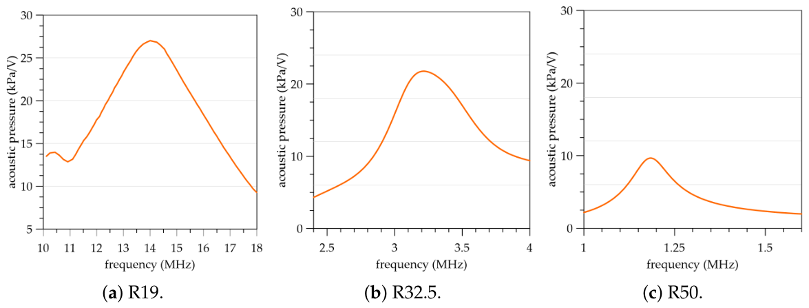
23], which dampens the pressure wave amplitude. This attenuation directly degrades Rx performance and must be quantified to accurately evaluate pMUT behavior. In this study, the attenuation coefficient of the ballistic gel is applied to the acoustic pressure measured at the Tx, see
Figure 5, by assuming conservatively a coefficient of reduction of
(consistent with [
24] and representative of thick human tissue [
22]). Consequently, total attenuation depends heavily on both the device operating frequency and the transmission distance. More precisely, the attenuation
a in decibels can be expressed as
, where
is the operating frequency in MHz and
d is the distance in cm. Considering the respective operating frequencies of the Rxs, the attenuation at a reference distance of 5 mm is 47.6% for the single R19 and 57% for the
R19 array. For the R32.5 and R50 variants, which operate at much lower frequencies, the attenuation drops significantly to 18% and 7%, respectively.
Table 5 summarizes the adjusted electrical performance parameters after accounting for acoustic attenuation.
Another critical parameter is the von Mises stress induced by the acoustic pressure reaching the Rx. If the peak stress exceeds the material yield strength, the top electrode will undergo plastic deformation, potentially leading to mechanical failure. Transient numerical simulations indicate a maximum von Mises stress of at the center of each R19 Rx pMUT. This value is well below the yield strength of the material (), ensuring that the pMUT operates strictly within its elastic regime, even under elevated driving voltages. The remaining layers of the pMUT exhibit even lower stress levels. For larger pMUT designs, stress levels are negligible as they are substantially lower than those observed in the R19 configuration.
Table 5 compares the performance of the different pMUT Rxs. As established in [
16], the stored energy per cycle scales as
(where
C is capacitance and
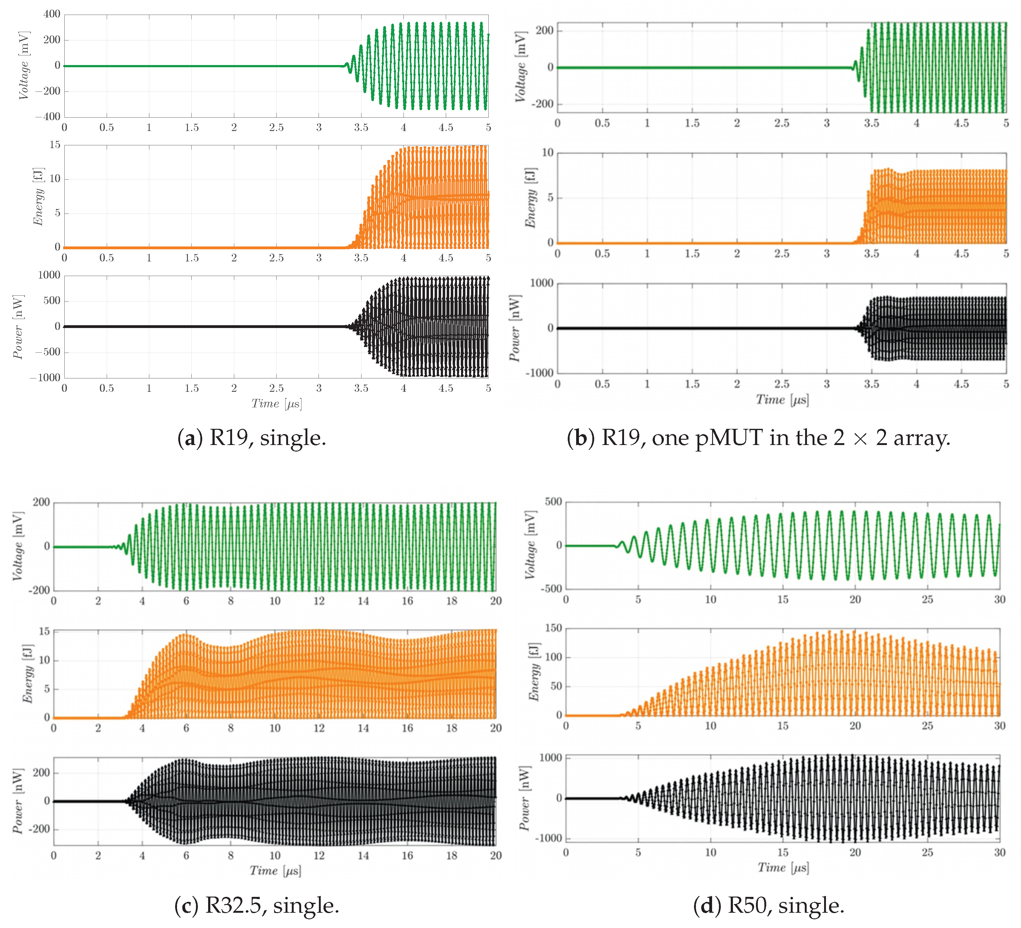
V is voltage); consequently, the energy stored by the R50 variant is approximately two orders of magnitude greater than that of the R19. The R32.5 configuration harvests several times more energy than the R19 variants, though it remains within the same order of magnitude.
Because the time-domain plots in
Figure 6 correspond to a piezoelectric device connected to a purely capacitive circuit, the average power must be evaluated across a reference resistive load to characterize the energy-harvesting capacity of each device. For a unit resistance, the steady-state average power can be defined as
, where
is the steady-state sinusoidal voltage amplitude after accounting for attenuation (see
Table 5). Incorporating the duty cycle yields the effective average power,
. The resulting average power values for a
load are listed in
Table 5 for the various Rxs. Notably, the duty cycle constraint imposes a severe limitation on the smaller R19 variants. Required for both the single and array configurations, this constraint significantly reduces the time-averaged availability of the voltage and power outputs.
The average power levels are adequate for digital electronics only in the case of the R32.5 and R50 variants; the output voltage and power for both the single R19 and the R19 array fall short of the design objectives. The R32.5 design yields a post-attenuation voltage output of 163 mV, which is comparable to that of the single R19. However, it provides a substantially higher average power and requires no duty cycle restrictions. This is a critical advantage for the design of the associated power-management and digital electronics, easily compensating for its slightly lower voltage compared to the single R19. The R50 achieves a remarkable voltage output of 324 mV. Consequently, while downsizing to a high-frequency pMUT, such as happens with the R19, increases power density and Rx sensitivity, it introduces strict duty cycle limitations to comply with FDA regulations. Furthermore, because acoustic attenuation scales with frequency, the operational range of high-frequency pMUTs is inherently restricted.
These performance metrics must be balanced against the physical footprint of each device, as listed in the final row of
Table 5. Given that the long-term objective is device miniaturization for intra-body biosensors, physical size heavily influences the selection of the optimal pMUT configuration. Accordingly, while the R50 delivers superior energy-harvesting performance and is the least affected by acoustic attenuation, its dimensions slightly exceed the area constraints specified in
Section 1.
Summarizing the results, the single R19 design in principle enables rapid operating speeds and provides a high power density relative to its size due to its high resonance frequency, but in practice, attenuation in the ballistic gel significantly degrades its performance. To maintain acceptable voltage and power levels, the duty cycle must be restricted to less than 10% for the array and approximately 30% for the single element. This constraint complicates the power management circuitry and curtails the operational distance between the Tx and Rx. The R32.5 strikes an optimal trade-off between these designs, despite its voltage falling below 200 mV once acoustic attenuation is factored in.
Finally, to contextualize the magnitude of the technical challenges involved, it is instructive to compare the power transmission efficiency (PTE) of these pMUTs with state-of-the-art devices reported in the literature. PTE is defined as the ratio between
, where
(
A being the Tx footprint), and
is the average power, possibly accounting for the duty cycle. In the table, the input and output powers are given per unit area. As summarized in
Table 6, scaling down the device dimensions inherently elevates the operating frequency. This, in turn, increases acoustic medium attenuation and brings the system closer to the FDA exposure limits for emitted radiation. Although the performance values per unit area are (sometimes significantly) lower than those reported in the literature, it is important to emphasize that the primary challenge for future intra-body applications is to guarantee the baseline voltage and average power thresholds required to reliably power downstream digital electronics rather than to provide PTE comparable to that in other application fields.
5. Conclusions
This work presented a numerical study of several pMUT configurations reported in the literature for wireless energy harvesting in biomedical applications. These configurations were evaluated against strict design requirements, including FDA acoustic radiation limits, a footprint below , and biocompatibility. proved to be an excellent lead-free, CMOS-compatible alternative to PZT in terms of piezoelectric performance. Furthermore, given the inverse relationship between transmission and receiving sensitivity, a smaller ScAlN pMUT exhibits superior receiving capabilities, making it highly suitable for energy-harvesting applications.
Three alternative designs, designated as R50, R32.5, and R19, were compared at operating frequencies of 1.16 MHz, 3.25 MHz, and above 10 MHz, respectively. Although miniaturization enables high-frequency operation (> for R19), it also introduces increased cross-talk (a stiffening effect) between array elements, requires strict duty cycle constraints ( for the R19 array and 30% for the single R19 element), and exacerbates acoustic wave attenuation over distance. Despite having an area 25% larger than the specified design requirements, the largest device, R50, performs well due to its lower operating frequency and greater robustness, though it requires longer excitation bursts to reach a steady state. The intermediate-sized device, R32.5, avoids severe attenuation of the acoustic signal while achieving acceptable energy-harvesting performance, while maintaining a footprint of that remains within the design limit.
Consequently, the resonance frequency of the device proves to be a critical parameter for energy-harvesting applications. Although high frequencies offer the advantage of enabling high-speed operation, they also lead to significant wave attenuation in the ballistic gel because attenuation is frequency-dependent. The latter aspect can induce substantial energy losses; mitigating this effect will be a primary focus of future developments. Indeed, it is worth underscoring the dramatic increase in operating frequency between the R32.5 and R19 designs, which leaps from 3.25 MHz to approximately 14 MHz—a jump of more than 10 MHz. Therefore, it is highly practical to tune the operating frequency to precisely match the required electrical performance for such micro-scale applications. This will require the redesign and fabrication of a new pMUT geometry aiming to achieve a working frequency below 5 MHz with the smallest possible footprint allowed by micro-fabrication limits. Starting from the R32.5 dimensions, further size reductions can only be achieved by decreasing the thickness of the membrane layers to effectively manage the operating frequency. A non-incremental development would consider completely different geometries, even curved ones such as in [
26].
Future work will focus on the fabrication and experimental validation of optimized pMUTs using silicon-on-nothing processes. Additionally, simulations will be expanded to incorporate nonlinear, thermal, and viscoelastic effects. Experimental evaluations will also be conducted to assess residual stresses, wave attenuation in ballistic gel and actual biological media, and fatigue strength of the Rx devices, alongside the monolithic or heterogeneous integration of the MEMS pMUT array with CMOS circuitry.