
Accurate EDM Calibration of a Digital Twin for a Seven-Axis Robotic EDM System and 3D Offline Cutting Path †


Abstract
1. Introduction
- Discharge Current: The intensity of the electrical current passing through the workpiece and electrode determines the material removal rate and the size of the spark created. In context, this parameter will define the reaction forces acting on the cutting tool electrode [3].
- Pulse Duration (On-Time): This is the duration for which the current is applied during each pulse. It influences the amount of material removed and the heat generated during the spark. In context, together with the discharge current, these parameters will define the feasible feed rate for the cutting path program [4].
- Pulse Frequency (Off-Time): This refers to the interval between successive electrical discharges. This parameter affects the efficiency of material removal and the overall machining time. In context, along with the pulse duration and discharge current, these parameters will define the reaction force and the risky vibration on commonly low-stiffness robotic arms [3].
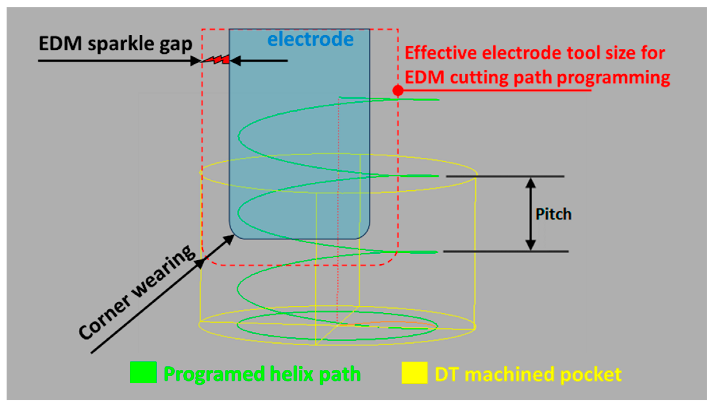
- Pulse Gap Distance: The distance where the voltage between the electrode and the workpiece tends to result in optimal material rate removal and a stable process. In context, this value varies from 5 to 100 μm and must be added to the electrode’s surface to define the cutting tool’s effective size and geometry [5].
- Electrode Material: The material used for the electrode impacts the machining rate, wear ratio, and surface finish. Common materials include copper, graphite, and tungsten. In context, depending on the material and amount of material to be removed, compensation movements must be added to the cutting path program to consider electrode wear and deliver an accurate cut [3].
- Dielectric Fluid: The type and condition of the dielectric (usually deionized water or oil) impact the flushing of debris, the cooling of the workpiece, and the efficiency of the process. In context, cutting path programs could include pre-defined retract movements with the intention of better flushing of debris for a more stable operation and improved surface roughness. It is important to note that for complex geometries, such as uneven surfaces, this retract movement is not a simplistic linear movement but a backwards movement consisting of reversing the programmed cutting path for a pre-defined length, speed, and time [3].
2. Literature Review on Digital Twins in the Manufacturing and Machining Context
2.1. The Concept of a Digital Twin
- Digital Twin Prototype (DTP) and Digital Twin Instance (DTI) [11], where DTP involves creating a virtual version for commissioning before making the physical twin, while DTI is connected to its physical counterpart throughout its lifecycle, enabling bidirectional data flow.
- Level of Integration [12], where a DT is called a Digital Model when it requires manual data exchange between the physical and digital objects, reflecting changes in one but not the other.
- Hierarchy [14], including Unit Level, System Level, and System of Systems (SoS) Level, classifies DTs based on the magnitude involved in manufacturing, from the smallest unit to interconnected systems.
- Level of Maturity and Sophistication [15] describes Partial DT, Clone DT, Augmented DT, Pre-Digital Twin, Digital Twin, Adaptive Digital Twin, and Intelligent Digital Twin [16]. These classifications rely on sophistication levels of data acquisition, ranging from basic data points to advanced capabilities like machine learning and real-time autonomous decision-making.
2.2. Applications of Digital Twins
2.3. Digital Twins in Robotic Machining
3. Development of a Robotic EDM Digital Twin
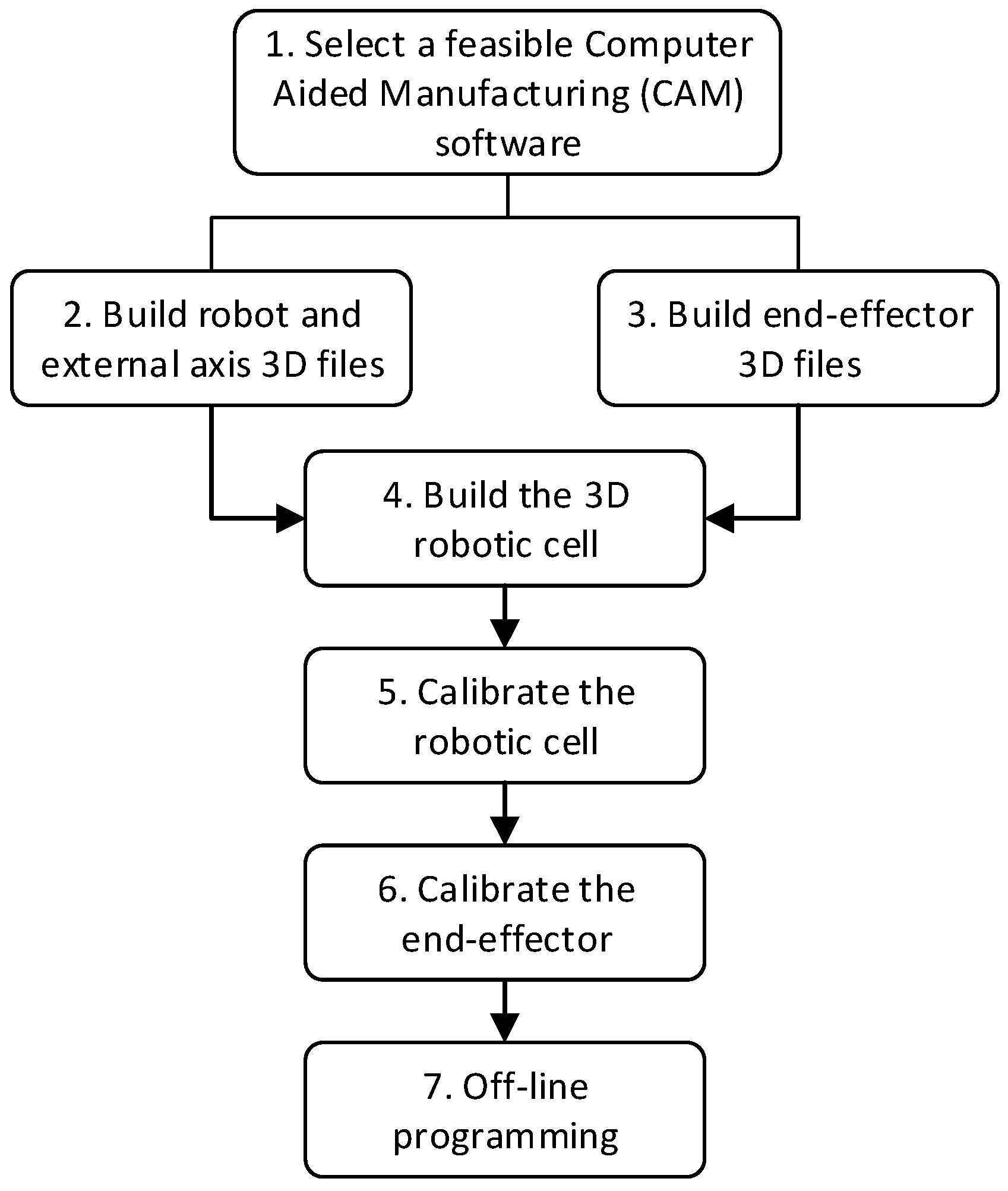
3.1. System Development Plan
3.2. Selecting Feasible CAM Software
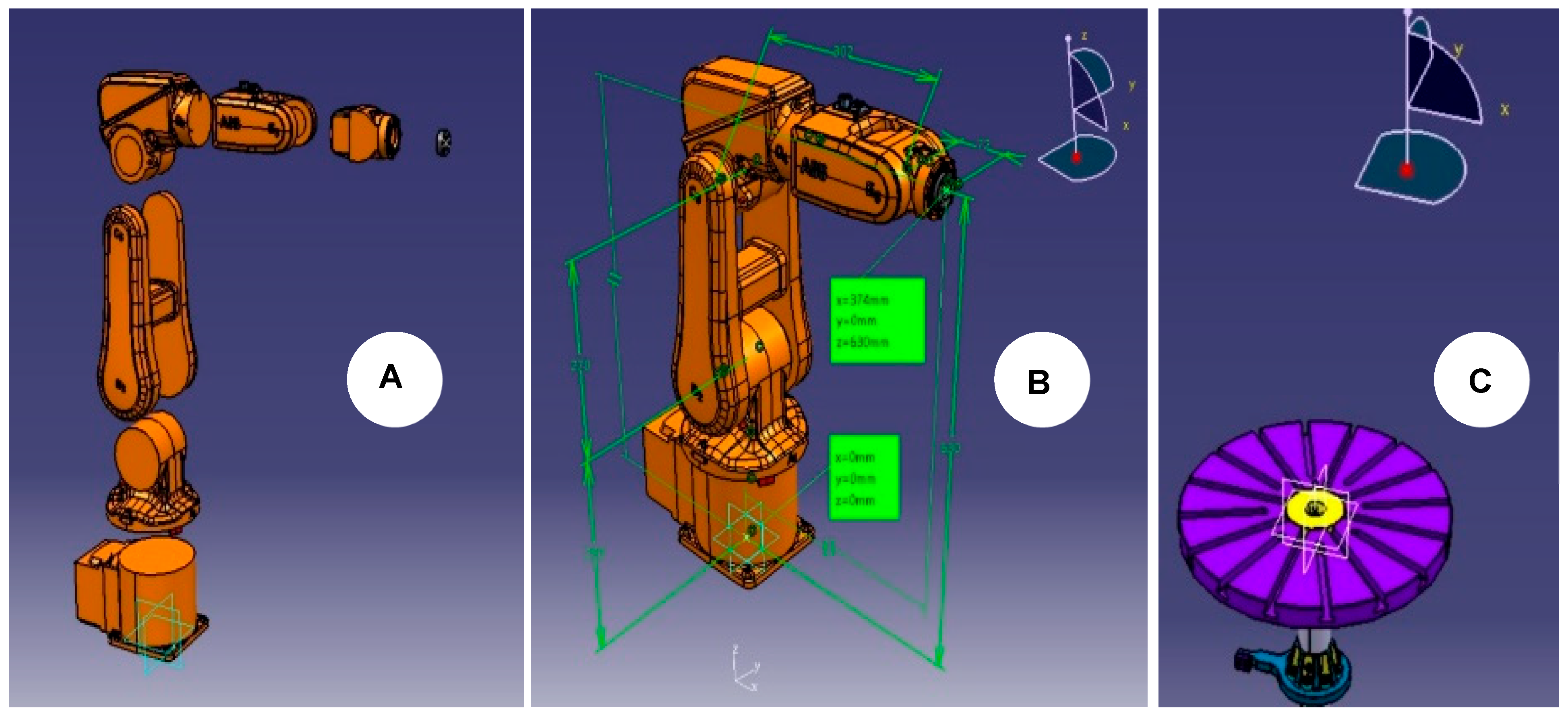
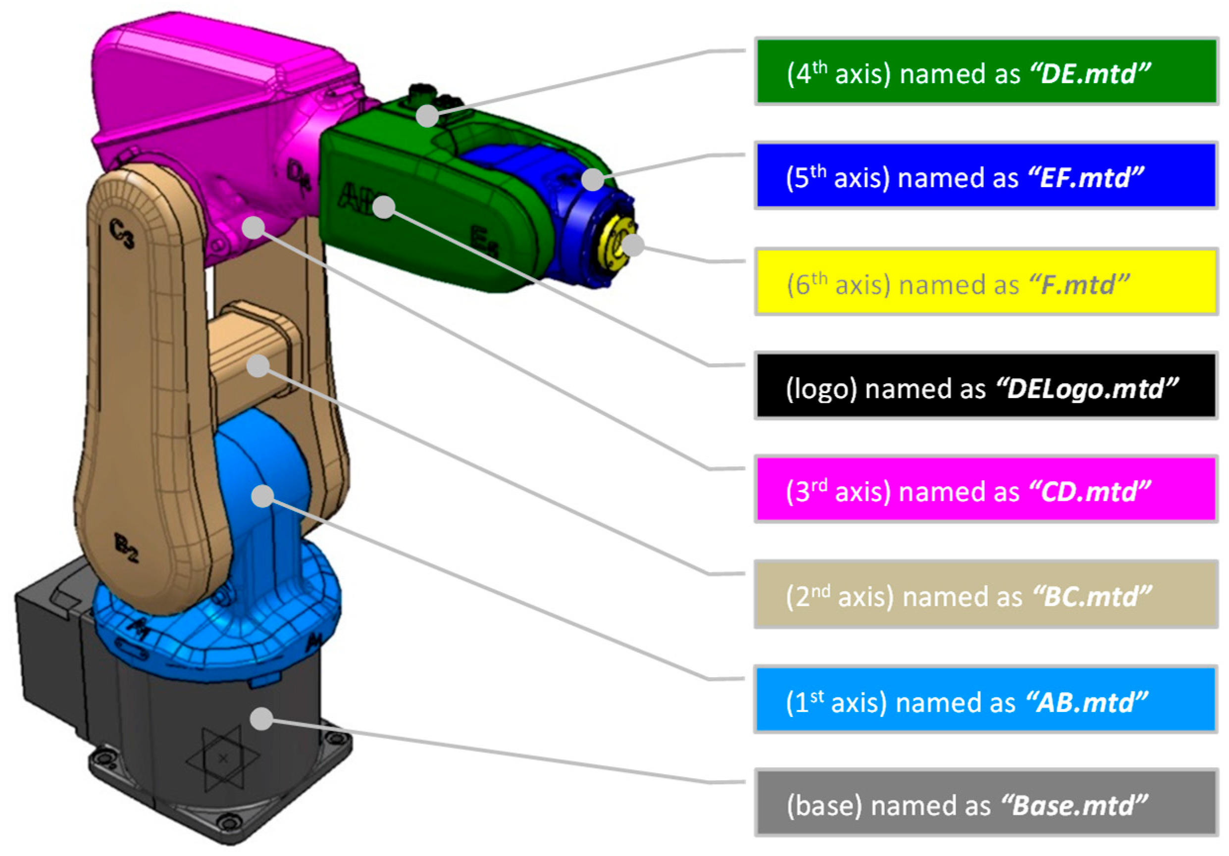
3.3. Building the Robot’s External 3D Models
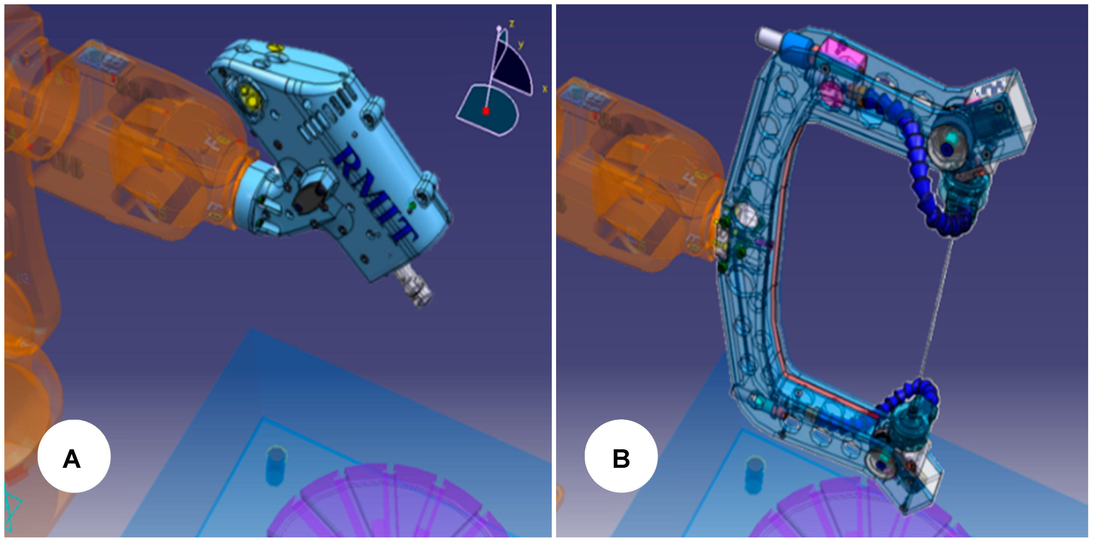
3.4. Build the End-Effectors 3D Models
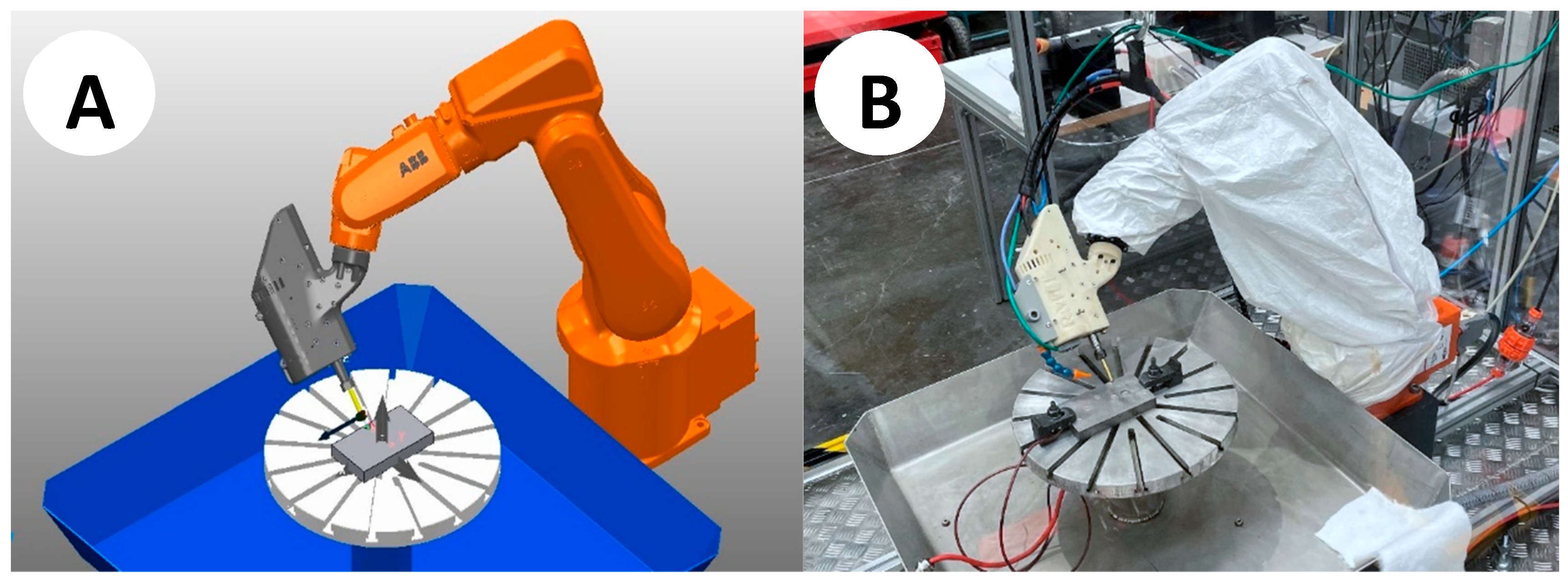
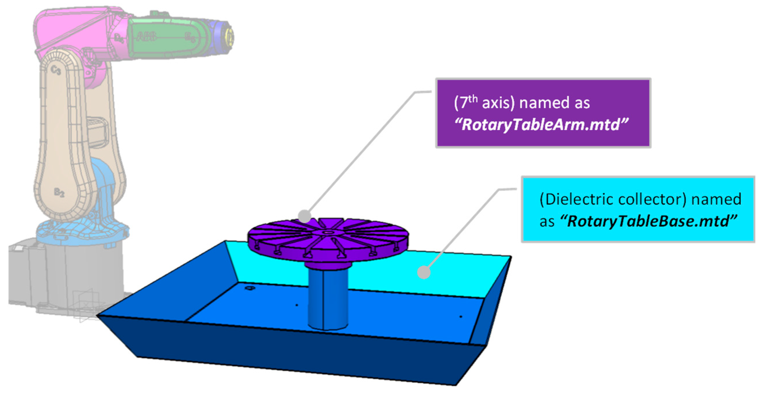
3.5. Building the 3D Robotic EDM Cell Environment
3.6. Calibration of the Robotic EDM Cell
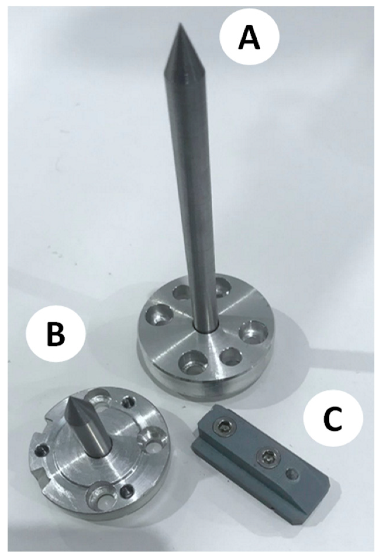
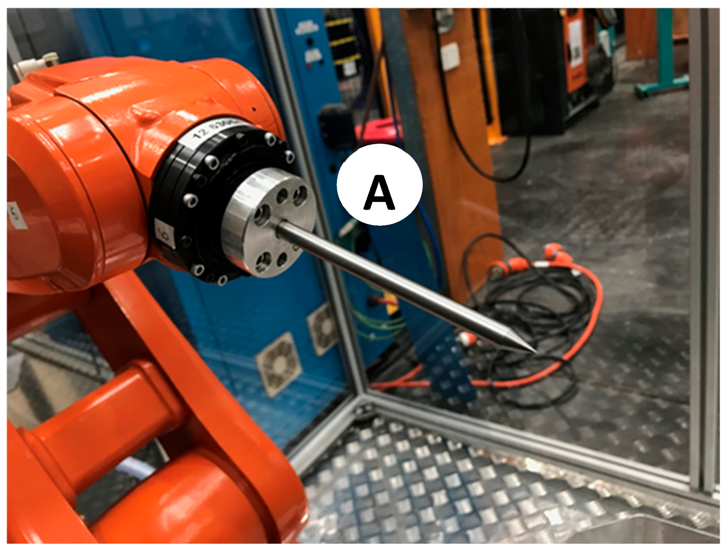
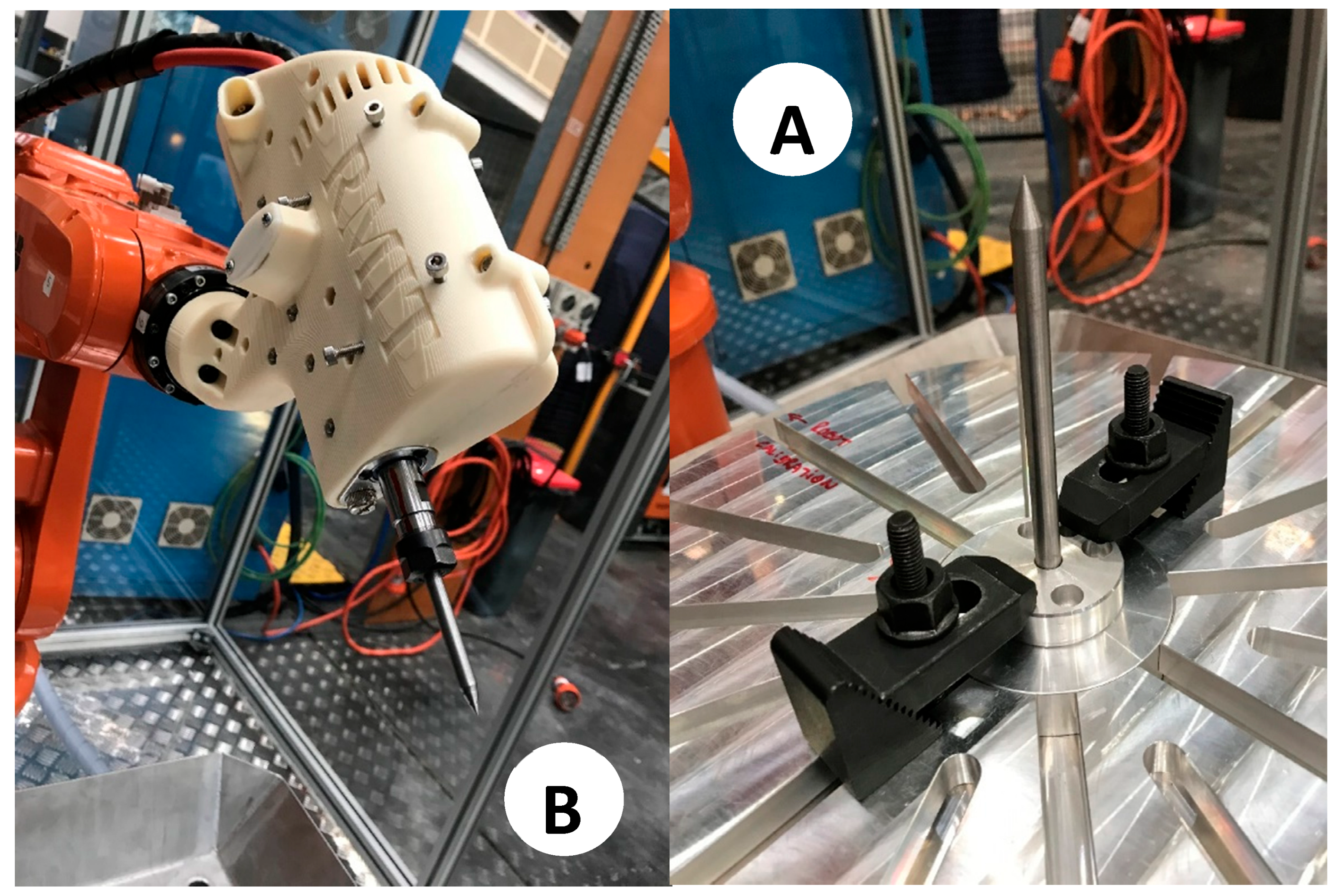
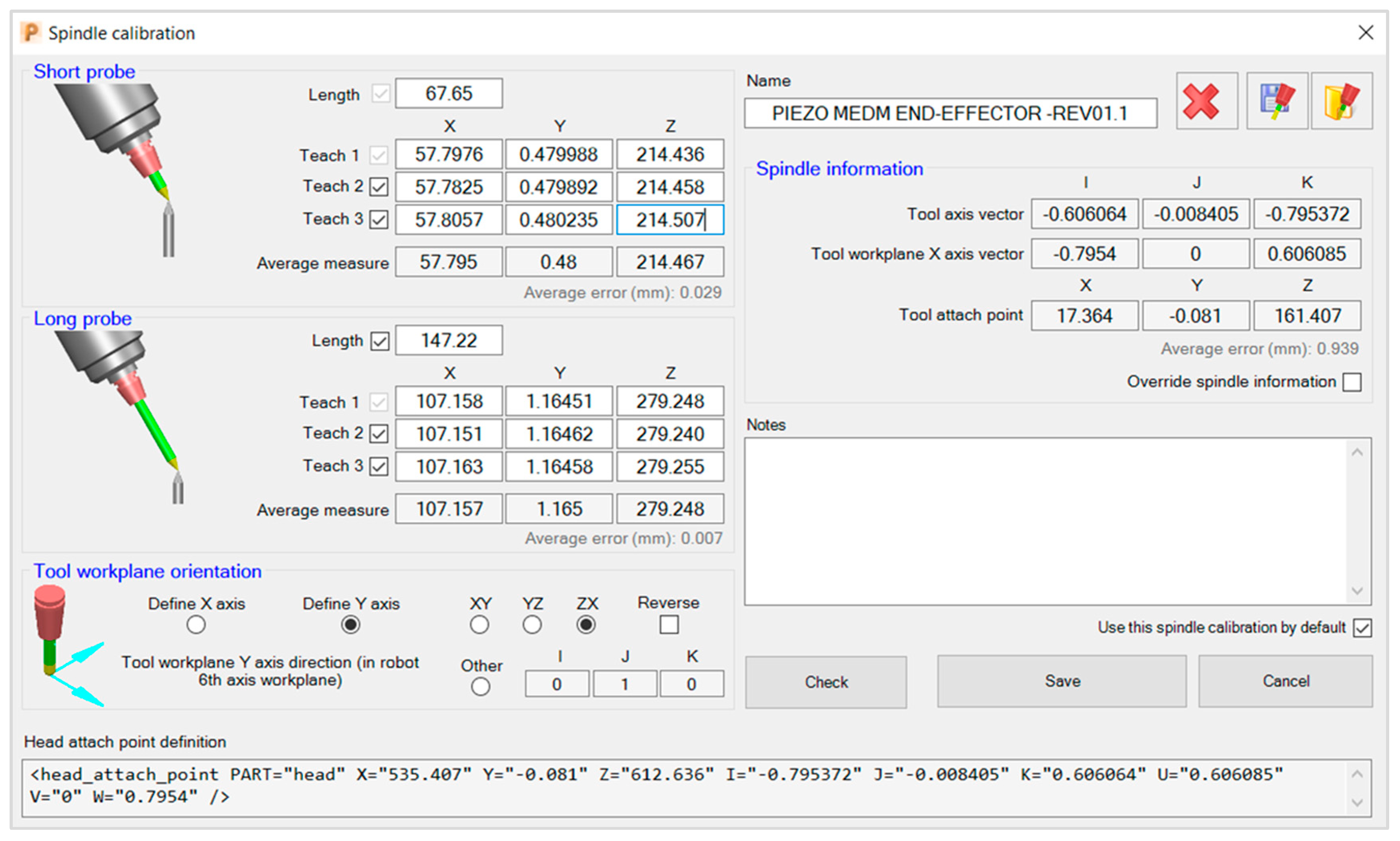
- Two long probes (Figure 8A) of Ø8 mm × 147.22 mm length are used for cell and end-effector calibration. Each of them comprises a central rod and a flange to allow for its direct assembly on the robot’s 6th axis.
- A short probe (Figure 8B) of Ø8 mm × 67.65 mm in length is used for cell and end-effector calibration. This probe is precisely the same as the long probe except for its length.
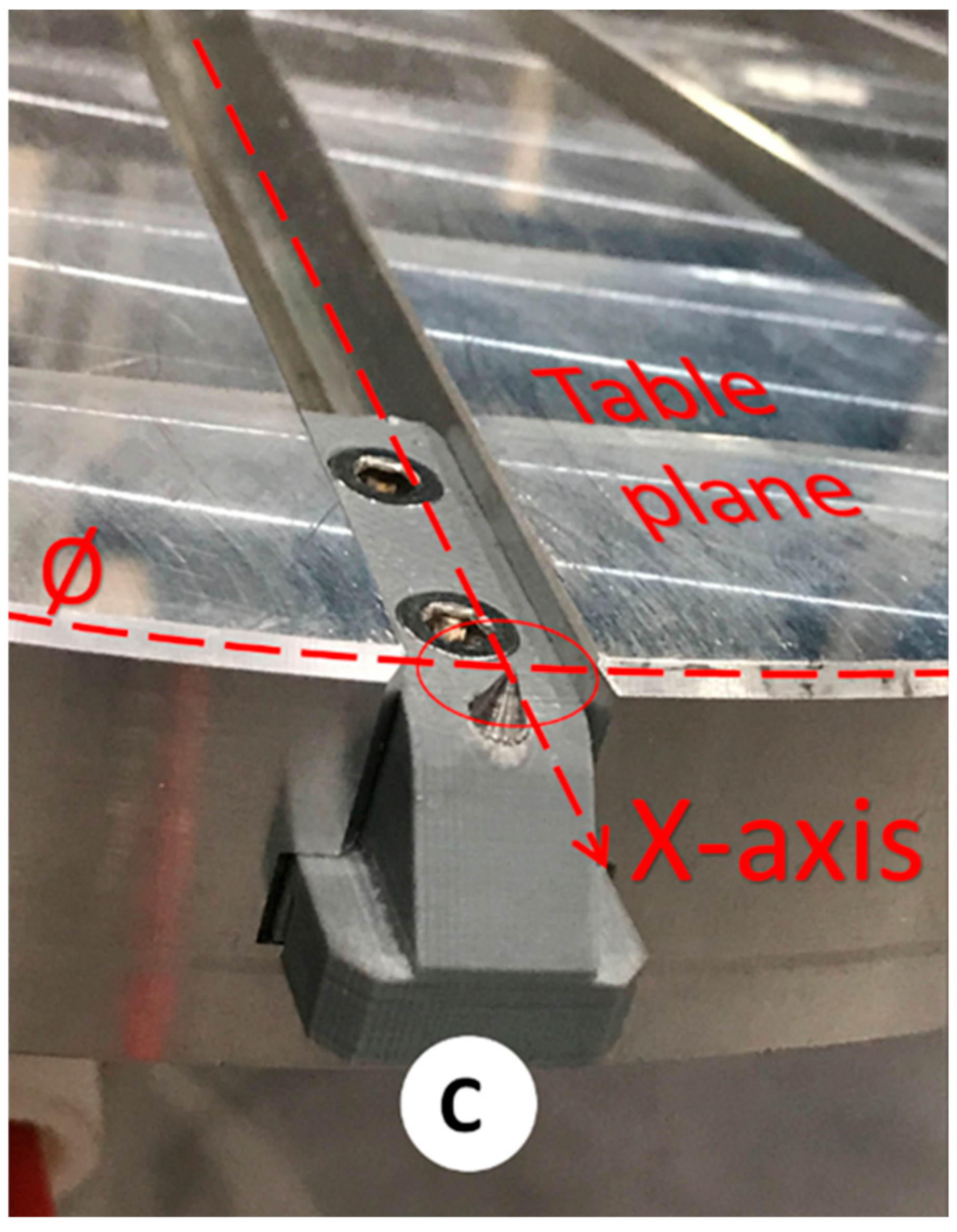
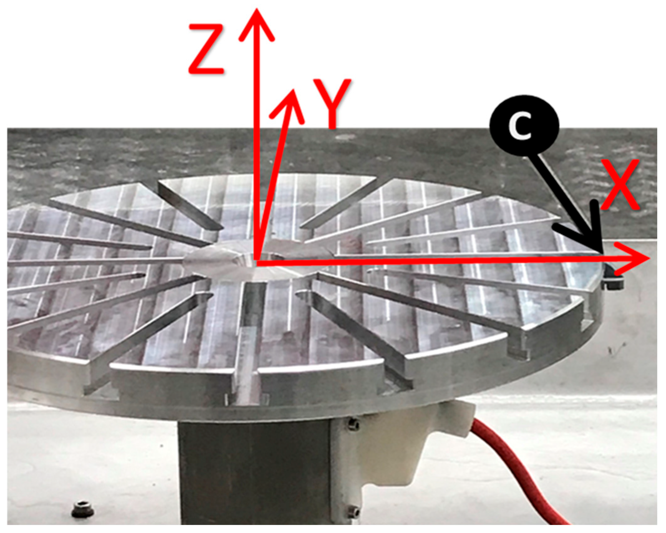
- A table probe (Figure 8C) composed of a 3D-printed body and an inserted metallic probe is designed to be assembled in the holding slots of the rotating table so that the tip of the probe can capture the table’s diameter, surface (working plane), and X-axis. Figure 9 presents the calibration assembly setup of probe C on the 7th axis.
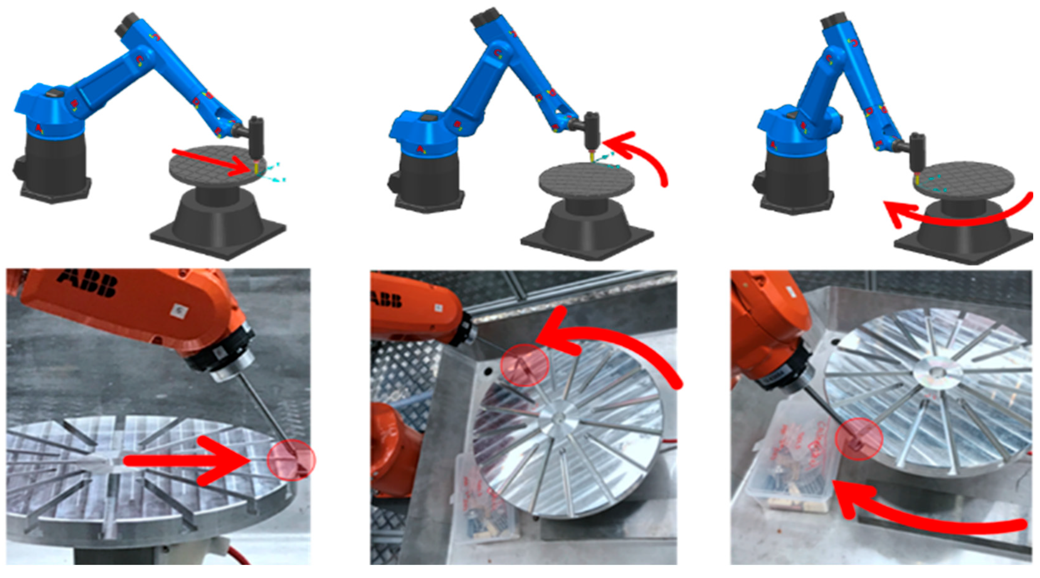
- First, the table is rotated at 0° to next assemble the table probe in the table slot, which theoretically coincides with the X-axis of the robot. Figure 11 shows the result.
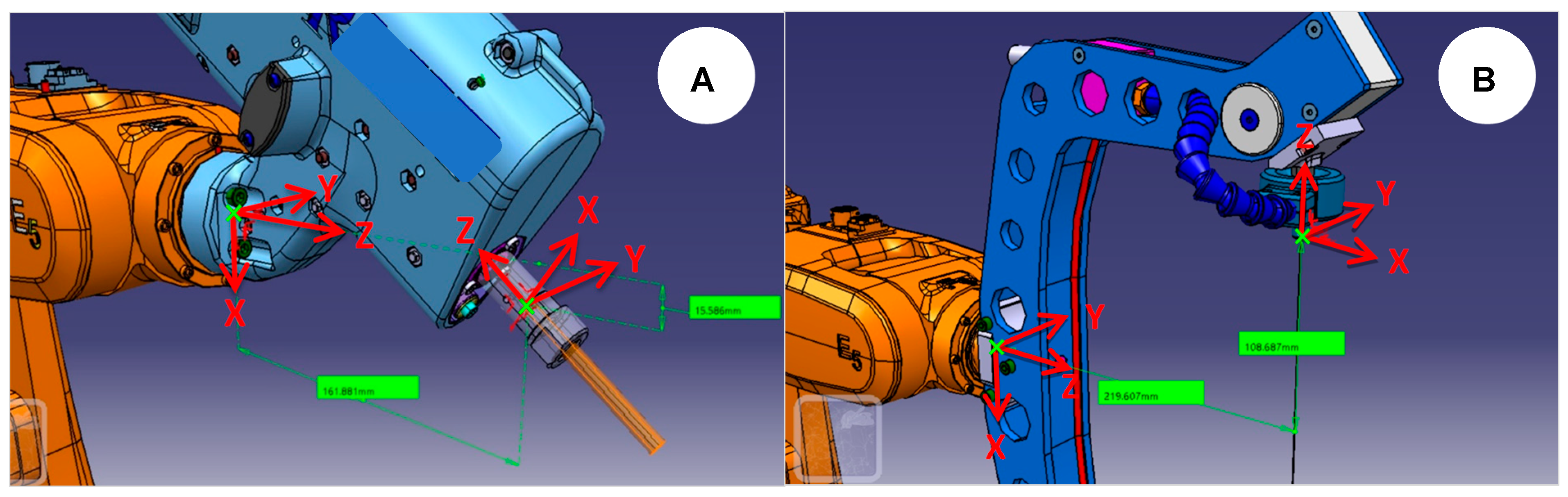
- Next, the long probe is assembled on the robot’s 6th axis as an end-effector, and its tip depicts the TCP so that the robot becomes a 3D measurement tool. Figure 12 shows the result.
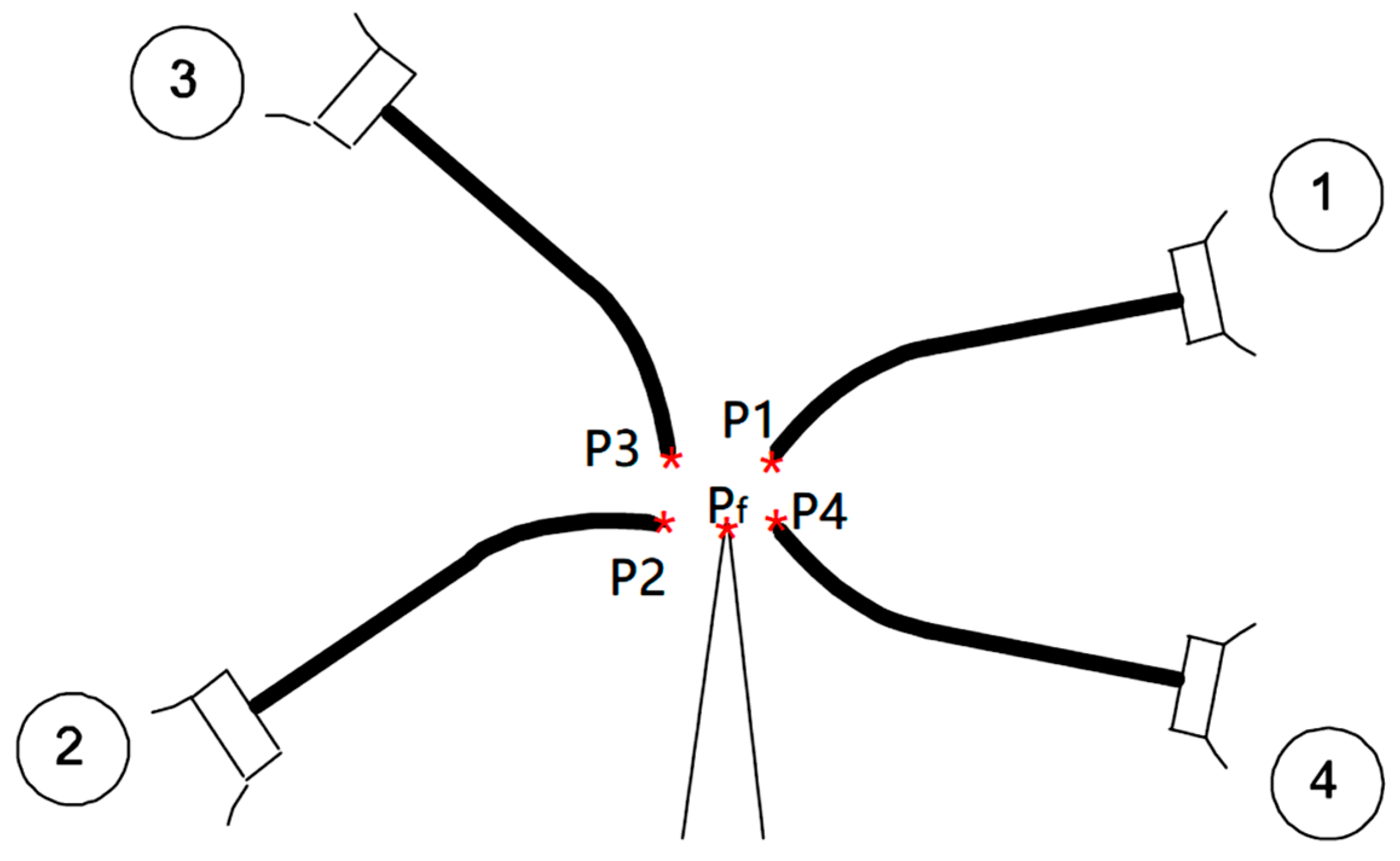
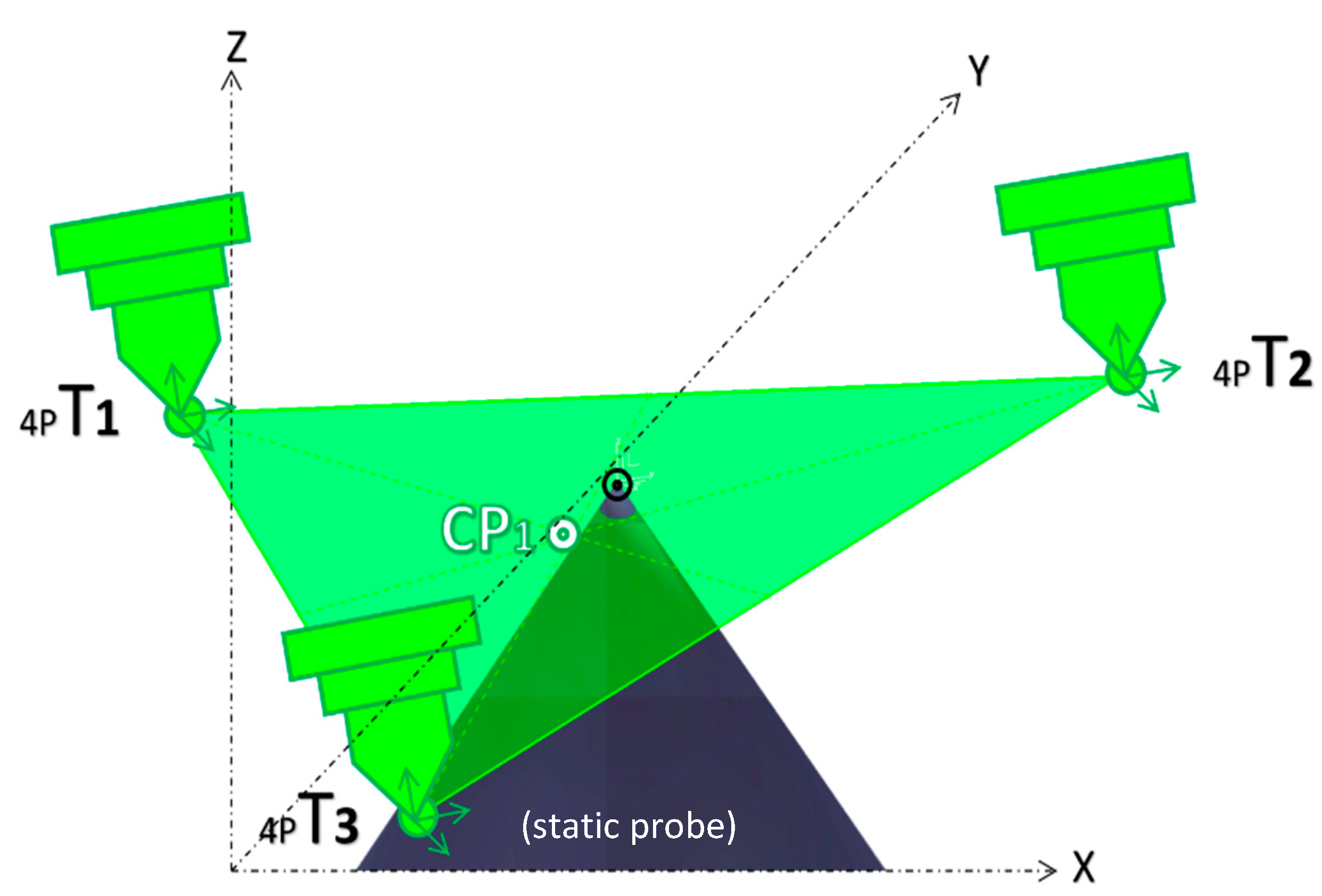
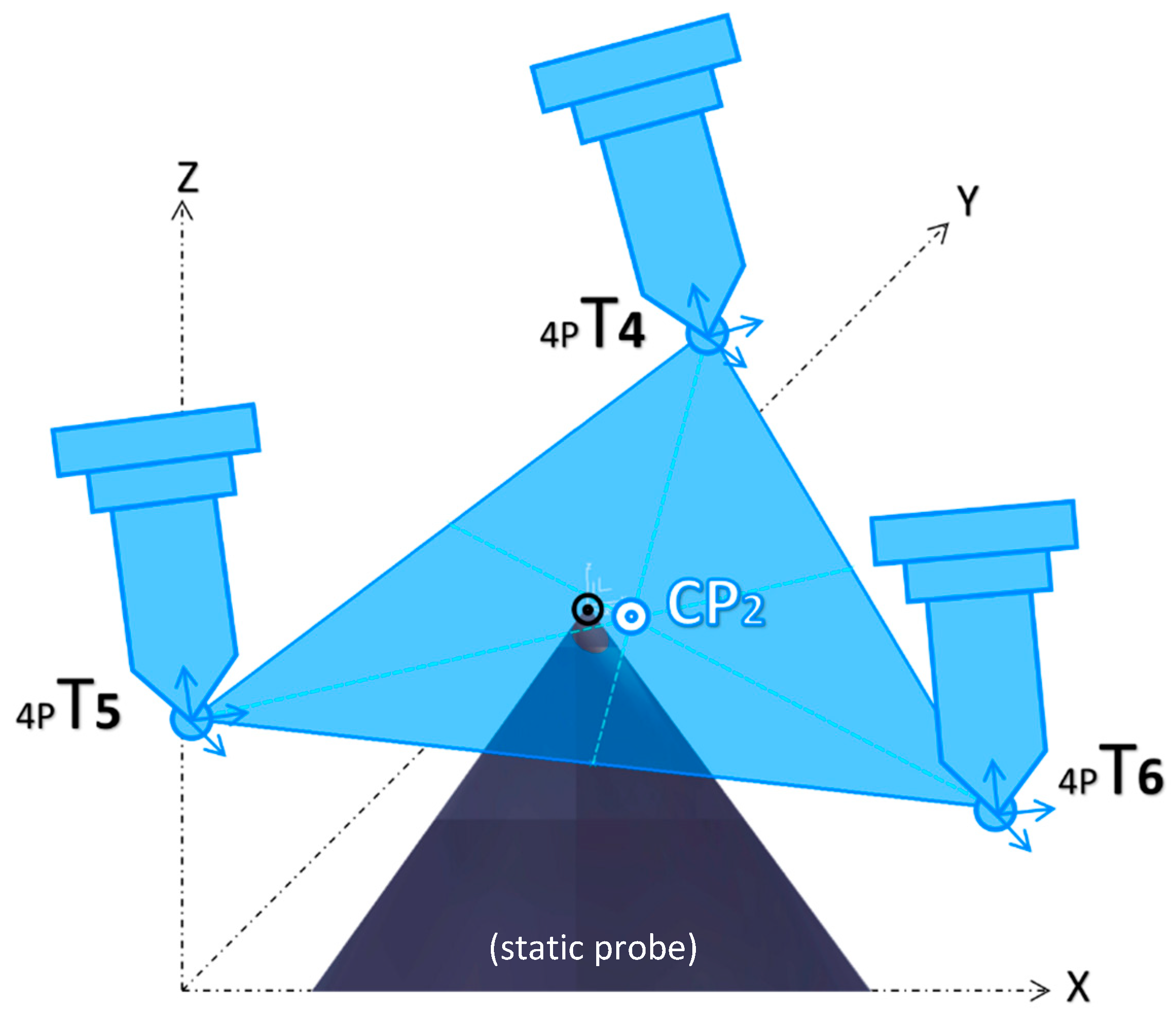
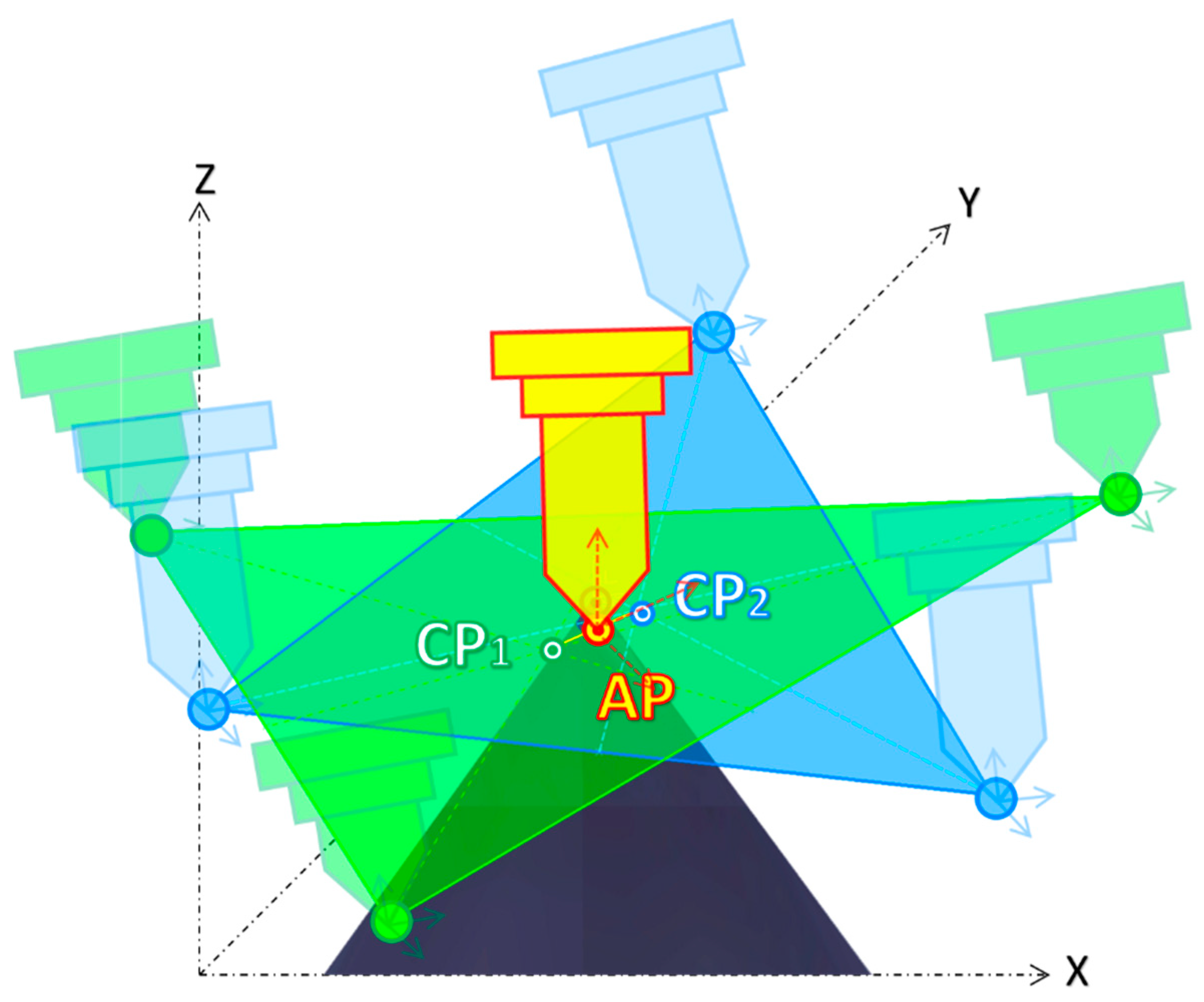
- Three different points in space can define a circle and its plane. Thus, to find the center of the rotating table and its working plan, three coordinates (XYZ) of three unique position points are measured. To find the three points, the table is rotated in intervals of 120°, starting at 60°, 180°, and 300°, aiming for them to be as far as possible from each other to enhance accuracy. Next, the robot is manually positioned so that the tip of the long probe is as close as possible to the tip of the table probe. Once the circle is found, it defines the central point of the rotating table and its supporting plan. Figure 13 summarizes this step.
- Next, the table is rotated back to 0°, and a new measurement of the Cartesian coordinates (XYZ) for the fourth point is acquired, which, together with the table center point, will define the X-axis table orientation.
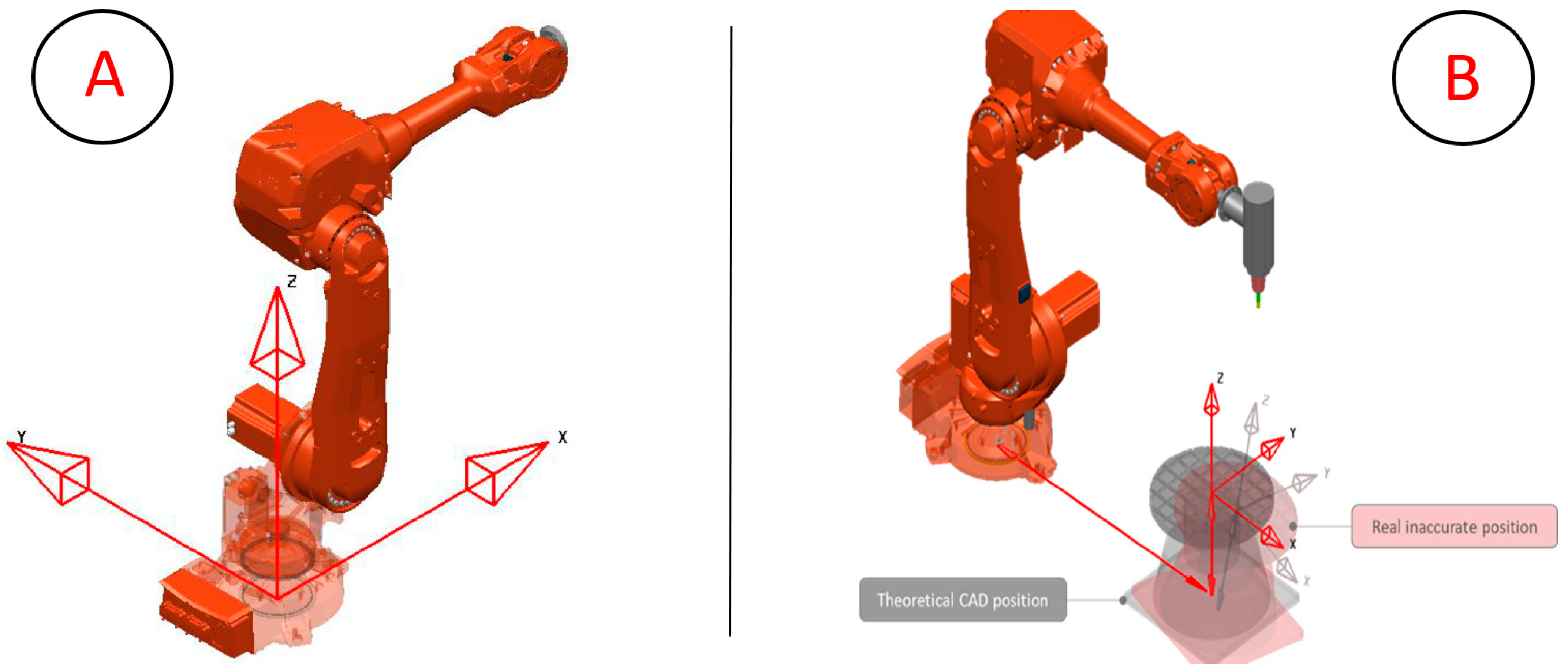
- Using PowerMill, each Cartesian coordinate X, Y, and Z of the four acquired points is used to calculate the actual position and orientation of the 7th axis to find the real center of the rotating table, as well as the table plan orientation.
- Finally, there are three final tasks to achieve an updated system that matches the detected errors. They consist of updating the identified deviations into the DT and physical systems involved, meaning (i) the ABB robot controller table center and orientation are updated, and (ii) the digital twin 3D CAD files modeled in the 3D CAD system CATIA are moved to reflect the errors, to then be re-exported, converted, and updated as previously described in Section 3.3, Section 3.4 and Section 3.5. Lastly, (iii) the PowerMill xml code files, responsible for defining the position, orientation, and rotation axes of the updated 3D CAD files, are updated.
3.7. Calibration of the EDM End-Effectors
4. Validation Results
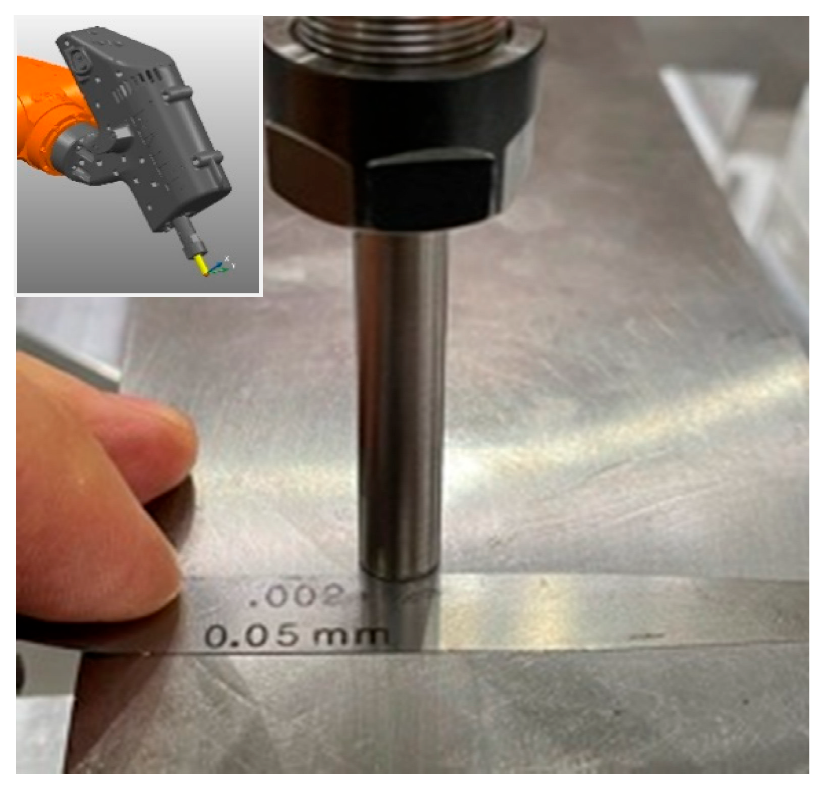
4.1. EDM Cutting Path Gap Accuracy
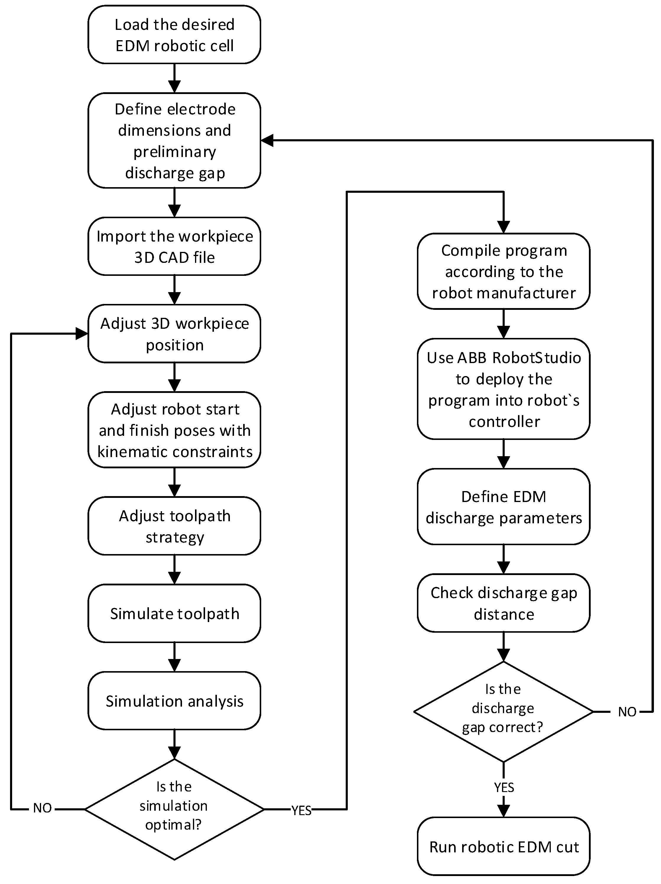
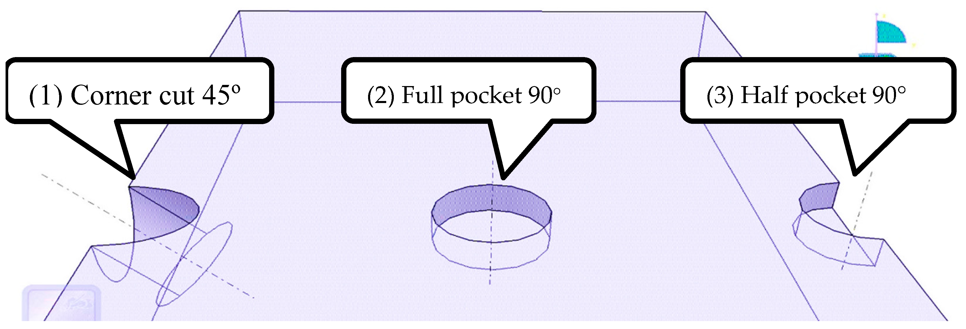
4.2. Experimental Validation of Offline Cutting Path Programming Using the DT
5. Conclusions
Author Contributions
Funding
Data Availability Statement
Conflicts of Interest
References
- Almeida, S.T.; Mo, J.P.T.; Bil, C.; Ding, S.; Wang, X. Servo Control Strategies for Vibration-Control in Robotic Wire EDM Machining. Arch. Comput. Methods Eng. 2021, 29, 113–127. [Google Scholar] [CrossRef]
- Almeida, S.; Mo, J.; Bil, C.; Ding, S.; Wang, X. Design of a Wire Cut EDM End-Effector with Strict Robotic Constraints. In Proceedings of the 28th ISTE International Conference on Transdisciplinary Engineering, Bath, UK, 29 April 2021; pp. 355–364. [Google Scholar]
- Almeida, S.; Mo, J.; Bil, C.; Ding, S. Accurate vibration-free robotic milling electric discharge machining. Int. J. Adv. Manuf. Technol. 2022, 122, 343–363. [Google Scholar] [CrossRef]
- Almeida, S.; Mo, J.; Bil, C.; Ding, S.; Wang, X. Comprehensive servo control strategies for flexible and high-efficient wire electric discharge machining. A Syst. review. Precis. Eng. 2021, 71, 7–28. [Google Scholar] [CrossRef]
- Almeida, S.; Mo, J.; Ding, S.; Bil, C. Control design of a reciprocating high-speed wire feed system for 7-axis robotic electric discharge machining. Int. J. Adv. Manuf. Technol. 2022, 121, 6877–6905. [Google Scholar] [CrossRef]
- Almeida, S.; Mo, J.; Bil, C.; Ding, S.; Cheng, C.-T. A Novel Robotic EDM Digital Twin for Offline Cutting-Path Programming. In Proceedings of the 30th ISTE International Conference on Transdisciplinary Engineering, Hua Hin Cha Am, Thailand, 11–14 July 2023. [Google Scholar]
- Grieves, M.; Vickers, J. Digital Twin: Mitigating Unpredictable, Undesirable Emergent Behavior in Complex Systems. In Transdisciplinary Perspectives on Complex Systems: New Findings and Approaches; Kahlen, F.-J., Flumerfelt, S., Alves, A., Eds.; Springer International Publishing: Cham, Switzerland, 2017; pp. 85–113. [Google Scholar]
- IPC-2551; International Standard for Digital Twins. IPC International: Bannockburn, IL, USA, 2020.
- IEEEP2806; System Architecture of Digital Representation for Physical Objects in Factory Environments. Institute of Electrical and Electronics Engineers: New York, NY, USA, 2019.
- ISO23247-1; Automation Systems and Integration—Digital Twin Framework for Manufacturing—Part 1: Overview and General Principles, in Specification and verification of balance tolerances and balance quality requirements. 2020 International Organization for Standardization: Geneva, Switzerland, 2020.
- Tao, F.; Zhang, M.; Nee, A.Y.C. Digital Twin Driven Smart Manufacturing; Academic Press: NewYork, NY, USA, 2019. [Google Scholar]
- Kritzinger, W.; Karner, M.; Traar, G.; Henjes, J.; Sihn, W. Digital Twin in manufacturing: A categorical literature review and classification. IFAC-PapersOnline 2018, 51, 1016–1022. [Google Scholar] [CrossRef]
- Almeida, H.A.; Vasco, J.C.; Marto, A.; Capela, C.; Freitas, D.; Craveiro, F.; Bártolo, H.; Coelho, L.; Correia, M.; Vieira, M. Progress in Digital and Physical Manufacturing; Springer: Berlin/Heidelberg, Germany, 2020. [Google Scholar]
- Tao, F.; Qi, Q.; Wang, L.; Nee, A.Y.C. Digital Twins and Cyber–Physical Systems toward Smart Manufacturing and Industry 4.0: Correlation and Comparison. Engineering 2019, 5, 653–661. [Google Scholar] [CrossRef]
- Perera, S.; Jin, X.; Das, P.; Gunasekara, K.; Samaratunga, M. A strategic framework for digital maturity of design and construction through a systematic review and application. J. Ind. Inf. Integr. 2023, 31, 100413. [Google Scholar] [CrossRef]
- Madni, A.M.; Madni, C.C.; Lucero, S.D. Leveraging Digital Twin Technology in Model-Based Systems Engineering. Systems 2019, 7, 7. [Google Scholar] [CrossRef]
- Singh, M.; Fuenmayor, E.; Hinchy, E.P.; Qiao, Y.; Murray, N.; Devine, D. Digital Twin: Origin to Future. Appl. Syst. Innov. 2021, 4, 36. [Google Scholar] [CrossRef]
- Uhlemann, T.H.J.; Lehmann, C.; Steinhilper, R. The Digital Twin: Realizing the Cyber-Physical Production System for Industry 4.0. Procedia CIRP 2017, 61, 335–340. [Google Scholar] [CrossRef]
- Altintas, Y.; Brecher, C.; Weck, M.; Witt, S. Virtual Machine Tool. CIRP Ann. 2005, 54, 115–138. [Google Scholar] [CrossRef]
- Huo, D.; Cheng, K.; Wardle, F. A holistic integrated dynamic design and modelling approach applied to the development of ultraprecision micro-milling machines. Int. J. Mach. Tools Manuf. 2010, 50, 335–343. [Google Scholar] [CrossRef]
- Guodong, S. Use Case Scenarios for Digital Twin Implementation Based on ISO 23247. Natl. Inst. Stand. Technol. (NIST) 2021, 30, 400-2. [Google Scholar] [CrossRef]
- Sommer, M.; Stjepandić, J.; Stobrawa, S.; Soden, M.v. Automated generation of digital twin for a built environment using scan and object detection as input for production planning. J. Ind. Inf. Integr. 2023, 33, 100462. [Google Scholar] [CrossRef]
- Ghosh, A.K.; Ullah, A.M.M.S.; Teti, R.; Kubo, A. Developing sensor signal-based digital twins for intelligent machine tools. J. Ind. Inf. Integr. 2021, 24, 100242. [Google Scholar] [CrossRef]
- Schreck, G.; Surdilovic, D.; Krueger, J. HEPHESTOS: Hard Material Small-Batch Industrial Machining Robot. In Proceedings of the ISR/Robotik 2014; 41st International Symposium on Robotics, Munich, Germany, 2–3 June 2014; pp. 1–6. [Google Scholar]
- Lehmann, C.; Pellicciari, M.; Drust, M.; Gunnink, J.W. Machining with Industrial Robots: The COMET Project Approach; Springer: Berlin/Heidelberg, Germany, 2013; pp. 27–36. [Google Scholar]
- Garnier, S.; Subrin, K.; Arevalo-Siles, P.; Caverot, G.; Furet, B. Mobile robot stability for complex tasks in naval industries. Procedia CIRP 2018, 72, 297–302. [Google Scholar] [CrossRef]
- Stavropoulos, P.; Manitaras, D.; Bikas, H.; Souflas, T. Integration of Machining Process Digital Twin in Early Design Stages of a Portable Robotic Machining Cell; Springer International Publishing: Cham, Switzerland, 2023; pp. 301–315. [Google Scholar]
- Zhu, Z.; Lin, Z.; Huang, J.; Zheng, L.; He, B. A digital twin-based machining motion simulation and visualization monitoring system for milling robot. Int. J. Adv. Manuf. Technol. 2023, 127, 4387–4399. [Google Scholar] [CrossRef]
- Ye, C.; Yang, J.; Zhao, H.; Ding, H. Task-dependent workpiece placement optimization for minimizing contour errors induced by the low posture-dependent stiffness of robotic milling. Int. J. Mech. Sci. 2021, 205, 106601. [Google Scholar] [CrossRef]
- Almeida, S.T. Robotic Multi-Axis Electric Discharge Machining of Exotic Hard-To-Cut Materials. Doctoral Dissertation, RMIT University, Melbourne, Australia, 2022. [Google Scholar]
- Lee, E.-S.; Suh, S.-H.; Shon, J.-W. A comprehensive method for calibration of volumetric positioning accuracy of CNC-machines. Int. J. Adv. Manuf. Technol. 1998, 14, 43–49. [Google Scholar] [CrossRef]
- Autodesk. PowerMill Ultimate CAM Software; Autodesk: San Rafael, CA, USA, 2020. [Google Scholar]
- ABB. RobotStudio Software; ABB: Zurich, Switzerland, 2019. [Google Scholar]
- Kwak, S.G.; Kim, J.H. Central limit theorem: The cornerstone of modern statistics. Korean J. Anesthesiol. 2017, 70, 144. [Google Scholar] [CrossRef]
- Ding, S.; Jiang, R. Tool path generation for 4-axis contour EDM rough machining. Int. J. Mach. Tools Manuf. 2004, 44, 1493–1502. [Google Scholar] [CrossRef]


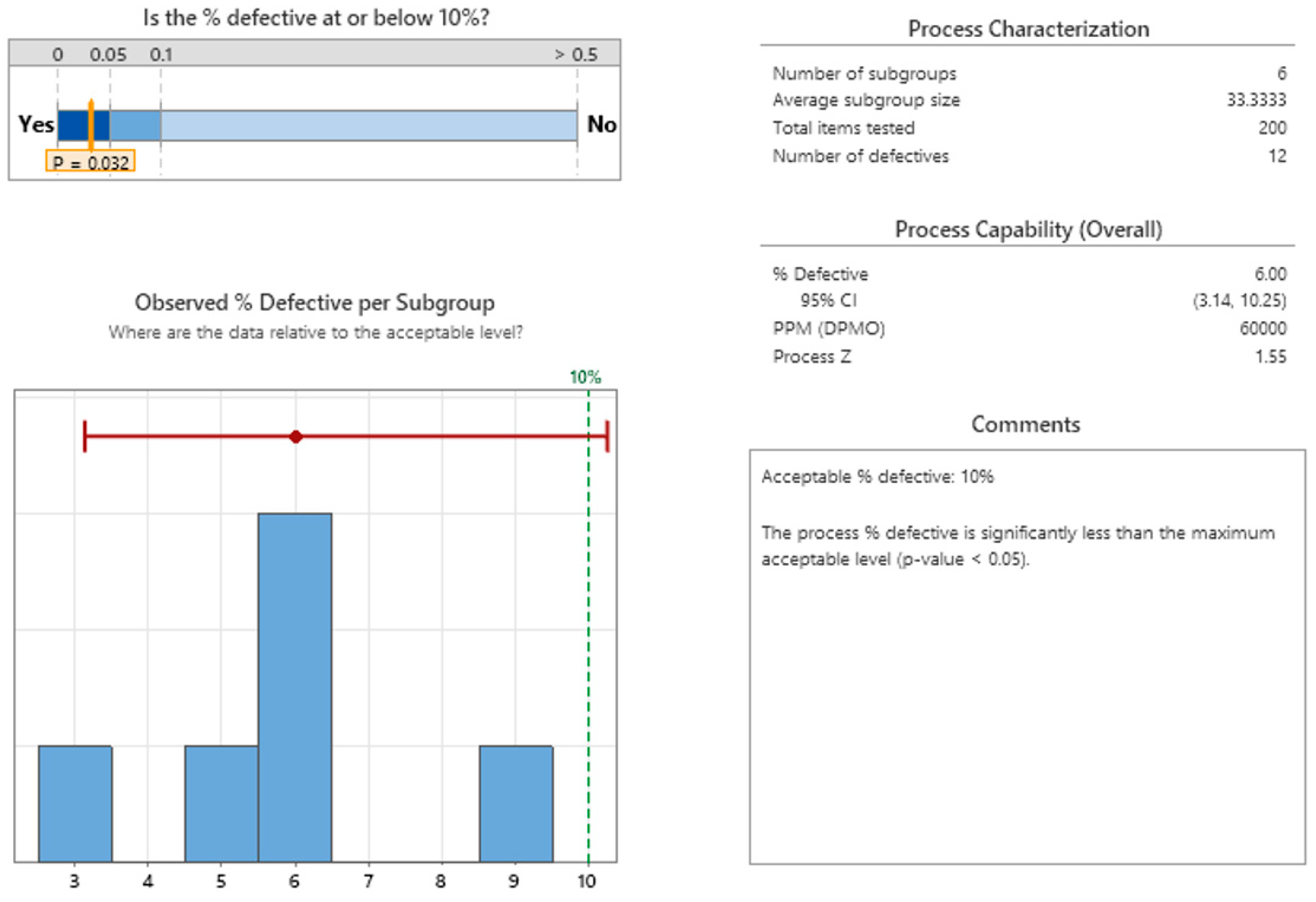
| Inspection Scenario | Gauge Thickness for Contact Detection | Considered Gap Interval (μm) | Attribute Result | |||
|---|---|---|---|---|---|---|
| 40 μm | 50 μm | 60 μm | Good | No-Good | ||
| Scenario 1 | no | no | no | g > 60 | 44 | |
| Scenario 2 | yes | no | no | 50 < g < 60 | 1 | |
| Scenario 3 | yes | yes | no | 40 < g < 50 | 43 | |
| Scenario 4 | yes | yes | yes | g < 40 | 2 | |
Disclaimer/Publisher’s Note: The statements, opinions and data contained in all publications are solely those of the individual author(s) and contributor(s) and not of MDPI and/or the editor(s). MDPI and/or the editor(s) disclaim responsibility for any injury to people or property resulting from any ideas, methods, instructions or products referred to in the content. |
© 2025 by the authors. Licensee MDPI, Basel, Switzerland. This article is an open access article distributed under the terms and conditions of the Creative Commons Attribution (CC BY) license (https://creativecommons.org/licenses/by/4.0/).
Share and Cite
de Almeida, S.T.; Mo, J.P.T.; Bil, C.; Ding, S.; Cheng, C.-T. Accurate EDM Calibration of a Digital Twin for a Seven-Axis Robotic EDM System and 3D Offline Cutting Path. Micromachines 2025, 16, 892. https://doi.org/10.3390/mi16080892
de Almeida ST, Mo JPT, Bil C, Ding S, Cheng C-T. Accurate EDM Calibration of a Digital Twin for a Seven-Axis Robotic EDM System and 3D Offline Cutting Path. Micromachines. 2025; 16(8):892. https://doi.org/10.3390/mi16080892
Chicago/Turabian Stylede Almeida, Sergio Tadeu, John P. T. Mo, Cees Bil, Songlin Ding, and Chi-Tsun Cheng. 2025. "Accurate EDM Calibration of a Digital Twin for a Seven-Axis Robotic EDM System and 3D Offline Cutting Path" Micromachines 16, no. 8: 892. https://doi.org/10.3390/mi16080892
APA Stylede Almeida, S. T., Mo, J. P. T., Bil, C., Ding, S., & Cheng, C.-T. (2025). Accurate EDM Calibration of a Digital Twin for a Seven-Axis Robotic EDM System and 3D Offline Cutting Path. Micromachines, 16(8), 892. https://doi.org/10.3390/mi16080892